EP1674282A2 - Kinematisches Bild durch Orientierung ausrichtbarer Pigmentflocken - Google Patents
Kinematisches Bild durch Orientierung ausrichtbarer Pigmentflocken Download PDFInfo
- Publication number
- EP1674282A2 EP1674282A2 EP05028190A EP05028190A EP1674282A2 EP 1674282 A2 EP1674282 A2 EP 1674282A2 EP 05028190 A EP05028190 A EP 05028190A EP 05028190 A EP05028190 A EP 05028190A EP 1674282 A2 EP1674282 A2 EP 1674282A2
- Authority
- EP
- European Patent Office
- Prior art keywords
- image
- flakes
- appears
- move
- kinematic
- Prior art date
- Legal status (The legal status is an assumption and is not a legal conclusion. Google has not performed a legal analysis and makes no representation as to the accuracy of the status listed.)
- Granted
Links
Images






Classifications
-
- B—PERFORMING OPERATIONS; TRANSPORTING
- B42—BOOKBINDING; ALBUMS; FILES; SPECIAL PRINTED MATTER
- B42D—BOOKS; BOOK COVERS; LOOSE LEAVES; PRINTED MATTER CHARACTERISED BY IDENTIFICATION OR SECURITY FEATURES; PRINTED MATTER OF SPECIAL FORMAT OR STYLE NOT OTHERWISE PROVIDED FOR; DEVICES FOR USE THEREWITH AND NOT OTHERWISE PROVIDED FOR; MOVABLE-STRIP WRITING OR READING APPARATUS
- B42D25/00—Information-bearing cards or sheet-like structures characterised by identification or security features; Manufacture thereof
- B42D25/30—Identification or security features, e.g. for preventing forgery
- B42D25/36—Identification or security features, e.g. for preventing forgery comprising special materials
- B42D25/369—Magnetised or magnetisable materials
-
- G—PHYSICS
- G03—PHOTOGRAPHY; CINEMATOGRAPHY; ANALOGOUS TECHNIQUES USING WAVES OTHER THAN OPTICAL WAVES; ELECTROGRAPHY; HOLOGRAPHY
- G03H—HOLOGRAPHIC PROCESSES OR APPARATUS
- G03H1/00—Holographic processes or apparatus using light, infrared or ultraviolet waves for obtaining holograms or for obtaining an image from them; Details peculiar thereto
- G03H1/04—Processes or apparatus for producing holograms
-
- B—PERFORMING OPERATIONS; TRANSPORTING
- B05—SPRAYING OR ATOMISING IN GENERAL; APPLYING FLUENT MATERIALS TO SURFACES, IN GENERAL
- B05D—PROCESSES FOR APPLYING FLUENT MATERIALS TO SURFACES, IN GENERAL
- B05D3/00—Pretreatment of surfaces to which liquids or other fluent materials are to be applied; After-treatment of applied coatings, e.g. intermediate treating of an applied coating preparatory to subsequent applications of liquids or other fluent materials
- B05D3/20—Pretreatment of surfaces to which liquids or other fluent materials are to be applied; After-treatment of applied coatings, e.g. intermediate treating of an applied coating preparatory to subsequent applications of liquids or other fluent materials by magnetic fields
- B05D3/207—Pretreatment of surfaces to which liquids or other fluent materials are to be applied; After-treatment of applied coatings, e.g. intermediate treating of an applied coating preparatory to subsequent applications of liquids or other fluent materials by magnetic fields post-treatment by magnetic fields
-
- B—PERFORMING OPERATIONS; TRANSPORTING
- B05—SPRAYING OR ATOMISING IN GENERAL; APPLYING FLUENT MATERIALS TO SURFACES, IN GENERAL
- B05D—PROCESSES FOR APPLYING FLUENT MATERIALS TO SURFACES, IN GENERAL
- B05D5/00—Processes for applying liquids or other fluent materials to surfaces to obtain special surface effects, finishes or structures
- B05D5/06—Processes for applying liquids or other fluent materials to surfaces to obtain special surface effects, finishes or structures to obtain multicolour or other optical effects
- B05D5/061—Special surface effect
-
- B—PERFORMING OPERATIONS; TRANSPORTING
- B41—PRINTING; LINING MACHINES; TYPEWRITERS; STAMPS
- B41M—PRINTING, DUPLICATING, MARKING, OR COPYING PROCESSES; COLOUR PRINTING
- B41M3/00—Printing processes to produce particular kinds of printed work, e.g. patterns
- B41M3/14—Security printing
- B41M3/148—Transitory images, i.e. images only visible from certain viewing angles
-
- B—PERFORMING OPERATIONS; TRANSPORTING
- B42—BOOKBINDING; ALBUMS; FILES; SPECIAL PRINTED MATTER
- B42D—BOOKS; BOOK COVERS; LOOSE LEAVES; PRINTED MATTER CHARACTERISED BY IDENTIFICATION OR SECURITY FEATURES; PRINTED MATTER OF SPECIAL FORMAT OR STYLE NOT OTHERWISE PROVIDED FOR; DEVICES FOR USE THEREWITH AND NOT OTHERWISE PROVIDED FOR; MOVABLE-STRIP WRITING OR READING APPARATUS
- B42D25/00—Information-bearing cards or sheet-like structures characterised by identification or security features; Manufacture thereof
-
- B—PERFORMING OPERATIONS; TRANSPORTING
- B42—BOOKBINDING; ALBUMS; FILES; SPECIAL PRINTED MATTER
- B42D—BOOKS; BOOK COVERS; LOOSE LEAVES; PRINTED MATTER CHARACTERISED BY IDENTIFICATION OR SECURITY FEATURES; PRINTED MATTER OF SPECIAL FORMAT OR STYLE NOT OTHERWISE PROVIDED FOR; DEVICES FOR USE THEREWITH AND NOT OTHERWISE PROVIDED FOR; MOVABLE-STRIP WRITING OR READING APPARATUS
- B42D25/00—Information-bearing cards or sheet-like structures characterised by identification or security features; Manufacture thereof
- B42D25/20—Information-bearing cards or sheet-like structures characterised by identification or security features; Manufacture thereof characterised by a particular use or purpose
- B42D25/29—Securities; Bank notes
-
- B—PERFORMING OPERATIONS; TRANSPORTING
- B42—BOOKBINDING; ALBUMS; FILES; SPECIAL PRINTED MATTER
- B42D—BOOKS; BOOK COVERS; LOOSE LEAVES; PRINTED MATTER CHARACTERISED BY IDENTIFICATION OR SECURITY FEATURES; PRINTED MATTER OF SPECIAL FORMAT OR STYLE NOT OTHERWISE PROVIDED FOR; DEVICES FOR USE THEREWITH AND NOT OTHERWISE PROVIDED FOR; MOVABLE-STRIP WRITING OR READING APPARATUS
- B42D25/00—Information-bearing cards or sheet-like structures characterised by identification or security features; Manufacture thereof
- B42D25/30—Identification or security features, e.g. for preventing forgery
-
- B—PERFORMING OPERATIONS; TRANSPORTING
- B44—DECORATIVE ARTS
- B44F—SPECIAL DESIGNS OR PICTURES
- B44F1/00—Designs or pictures characterised by special or unusual light effects
- B44F1/08—Designs or pictures characterised by special or unusual light effects characterised by colour effects
- B44F1/10—Changing, amusing, or secret pictures
-
- B—PERFORMING OPERATIONS; TRANSPORTING
- B44—DECORATIVE ARTS
- B44F—SPECIAL DESIGNS OR PICTURES
- B44F7/00—Designs imitating three-dimensional [3D] effects
-
- G—PHYSICS
- G06—COMPUTING OR CALCULATING; COUNTING
- G06K—GRAPHICAL DATA READING; PRESENTATION OF DATA; RECORD CARRIERS; HANDLING RECORD CARRIERS
- G06K19/00—Record carriers for use with machines and with at least a part designed to carry digital markings
- G06K19/06—Record carriers for use with machines and with at least a part designed to carry digital markings characterised by the kind of the digital marking, e.g. shape, nature, code
- G06K19/08—Record carriers for use with machines and with at least a part designed to carry digital markings characterised by the kind of the digital marking, e.g. shape, nature, code using markings of different kinds or more than one marking of the same kind in the same record carrier, e.g. one marking being sensed by optical and the other by magnetic means
- G06K19/10—Record carriers for use with machines and with at least a part designed to carry digital markings characterised by the kind of the digital marking, e.g. shape, nature, code using markings of different kinds or more than one marking of the same kind in the same record carrier, e.g. one marking being sensed by optical and the other by magnetic means at least one kind of marking being used for authentication, e.g. of credit or identity cards
-
- B—PERFORMING OPERATIONS; TRANSPORTING
- B05—SPRAYING OR ATOMISING IN GENERAL; APPLYING FLUENT MATERIALS TO SURFACES, IN GENERAL
- B05D—PROCESSES FOR APPLYING FLUENT MATERIALS TO SURFACES, IN GENERAL
- B05D7/00—Processes, other than flocking, specially adapted for applying liquids or other fluent materials to particular surfaces or for applying particular liquids or other fluent materials
- B05D7/50—Multilayers
- B05D7/52—Two layers
- B05D7/54—No clear coat specified
- B05D7/546—No clear coat specified each layer being cured, at least partially, separately
-
- B42D2033/18—
-
- Y—GENERAL TAGGING OF NEW TECHNOLOGICAL DEVELOPMENTS; GENERAL TAGGING OF CROSS-SECTIONAL TECHNOLOGIES SPANNING OVER SEVERAL SECTIONS OF THE IPC; TECHNICAL SUBJECTS COVERED BY FORMER USPC CROSS-REFERENCE ART COLLECTIONS [XRACs] AND DIGESTS
- Y10—TECHNICAL SUBJECTS COVERED BY FORMER USPC
- Y10S—TECHNICAL SUBJECTS COVERED BY FORMER USPC CROSS-REFERENCE ART COLLECTIONS [XRACs] AND DIGESTS
- Y10S283/00—Printed matter
- Y10S283/901—Concealed data
-
- Y—GENERAL TAGGING OF NEW TECHNOLOGICAL DEVELOPMENTS; GENERAL TAGGING OF CROSS-SECTIONAL TECHNOLOGIES SPANNING OVER SEVERAL SECTIONS OF THE IPC; TECHNICAL SUBJECTS COVERED BY FORMER USPC CROSS-REFERENCE ART COLLECTIONS [XRACs] AND DIGESTS
- Y10—TECHNICAL SUBJECTS COVERED BY FORMER USPC
- Y10S—TECHNICAL SUBJECTS COVERED BY FORMER USPC CROSS-REFERENCE ART COLLECTIONS [XRACs] AND DIGESTS
- Y10S283/00—Printed matter
- Y10S283/902—Anti-photocopy
-
- Y—GENERAL TAGGING OF NEW TECHNOLOGICAL DEVELOPMENTS; GENERAL TAGGING OF CROSS-SECTIONAL TECHNOLOGIES SPANNING OVER SEVERAL SECTIONS OF THE IPC; TECHNICAL SUBJECTS COVERED BY FORMER USPC CROSS-REFERENCE ART COLLECTIONS [XRACs] AND DIGESTS
- Y10—TECHNICAL SUBJECTS COVERED BY FORMER USPC
- Y10S—TECHNICAL SUBJECTS COVERED BY FORMER USPC CROSS-REFERENCE ART COLLECTIONS [XRACs] AND DIGESTS
- Y10S428/00—Stock material or miscellaneous articles
- Y10S428/90—Magnetic feature
-
- Y—GENERAL TAGGING OF NEW TECHNOLOGICAL DEVELOPMENTS; GENERAL TAGGING OF CROSS-SECTIONAL TECHNOLOGIES SPANNING OVER SEVERAL SECTIONS OF THE IPC; TECHNICAL SUBJECTS COVERED BY FORMER USPC CROSS-REFERENCE ART COLLECTIONS [XRACs] AND DIGESTS
- Y10—TECHNICAL SUBJECTS COVERED BY FORMER USPC
- Y10S—TECHNICAL SUBJECTS COVERED BY FORMER USPC CROSS-REFERENCE ART COLLECTIONS [XRACs] AND DIGESTS
- Y10S428/00—Stock material or miscellaneous articles
- Y10S428/916—Fraud or tamper detecting
-
- Y—GENERAL TAGGING OF NEW TECHNOLOGICAL DEVELOPMENTS; GENERAL TAGGING OF CROSS-SECTIONAL TECHNOLOGIES SPANNING OVER SEVERAL SECTIONS OF THE IPC; TECHNICAL SUBJECTS COVERED BY FORMER USPC CROSS-REFERENCE ART COLLECTIONS [XRACs] AND DIGESTS
- Y10—TECHNICAL SUBJECTS COVERED BY FORMER USPC
- Y10T—TECHNICAL SUBJECTS COVERED BY FORMER US CLASSIFICATION
- Y10T428/00—Stock material or miscellaneous articles
- Y10T428/24—Structurally defined web or sheet [e.g., overall dimension, etc.]
- Y10T428/24802—Discontinuous or differential coating, impregnation or bond [e.g., artwork, printing, retouched photograph, etc.]
-
- Y—GENERAL TAGGING OF NEW TECHNOLOGICAL DEVELOPMENTS; GENERAL TAGGING OF CROSS-SECTIONAL TECHNOLOGIES SPANNING OVER SEVERAL SECTIONS OF THE IPC; TECHNICAL SUBJECTS COVERED BY FORMER USPC CROSS-REFERENCE ART COLLECTIONS [XRACs] AND DIGESTS
- Y10—TECHNICAL SUBJECTS COVERED BY FORMER USPC
- Y10T—TECHNICAL SUBJECTS COVERED BY FORMER US CLASSIFICATION
- Y10T428/00—Stock material or miscellaneous articles
- Y10T428/25—Web or sheet containing structurally defined element or component and including a second component containing structurally defined particles
-
- Y—GENERAL TAGGING OF NEW TECHNOLOGICAL DEVELOPMENTS; GENERAL TAGGING OF CROSS-SECTIONAL TECHNOLOGIES SPANNING OVER SEVERAL SECTIONS OF THE IPC; TECHNICAL SUBJECTS COVERED BY FORMER USPC CROSS-REFERENCE ART COLLECTIONS [XRACs] AND DIGESTS
- Y10—TECHNICAL SUBJECTS COVERED BY FORMER USPC
- Y10T—TECHNICAL SUBJECTS COVERED BY FORMER US CLASSIFICATION
- Y10T428/00—Stock material or miscellaneous articles
- Y10T428/29—Coated or structually defined flake, particle, cell, strand, strand portion, rod, filament, macroscopic fiber or mass thereof
- Y10T428/2982—Particulate matter [e.g., sphere, flake, etc.]
-
- Y—GENERAL TAGGING OF NEW TECHNOLOGICAL DEVELOPMENTS; GENERAL TAGGING OF CROSS-SECTIONAL TECHNOLOGIES SPANNING OVER SEVERAL SECTIONS OF THE IPC; TECHNICAL SUBJECTS COVERED BY FORMER USPC CROSS-REFERENCE ART COLLECTIONS [XRACs] AND DIGESTS
- Y10—TECHNICAL SUBJECTS COVERED BY FORMER USPC
- Y10T—TECHNICAL SUBJECTS COVERED BY FORMER US CLASSIFICATION
- Y10T428/00—Stock material or miscellaneous articles
- Y10T428/29—Coated or structually defined flake, particle, cell, strand, strand portion, rod, filament, macroscopic fiber or mass thereof
- Y10T428/2982—Particulate matter [e.g., sphere, flake, etc.]
- Y10T428/2991—Coated
Definitions
- This invention relates generally to optically variable pigments, films, inks, paints, devices, and images, and more particularly to images with aligned or oriented pigment flakes, for example, during a painting or printing process, to obtain an illusive optical effect.
- This invention is particularly applicable to aligning magnetically alignable pigment flakes and is also applicable to aligning non-magnetic dielectric or semiconductor flakes in an electric field.
- Optically variable devices are used in a wide variety of applications, both decorative and utilitarian. Optically variable devices can be made in variety of ways to achieve a variety of effects. Examples of optically variable devices include the holograms imprinted on credit cards and authentic software documentation, color-shifting images printed on banknotes, and enhancing the surface appearance of items such as motorcycle helmets and wheel covers.
- Optically variable devices can be made as film or foil that is pressed, stamped, glued, or otherwise attached to an object, and can also be made using optically variable pigments.
- One type of optically variable pigment is commonly called a color-shifting pigment because the apparent color of images appropriately printed with such pigments changes as the angle of view and/or illumination is tilted.
- a common example is the "20" printed with color-shifting pigment in the lower right-hand corner of a U.S. twenty-dollar bill, which serves as an anti-counterfeiting device.
- Some anti-counterfeiting devices are covert, while others are intended to be noticed.
- This invention relates to overt features, intended to be noticed, however flakes having covert features therein, such as indicia can be used. Furthermore flakes with gratings and holographic features can be used.
- some optically variable devices that are intended to be noticed are not widely known because the optically variable aspect of the device is not sufficiently dramatic. For example, the color shift of an image printed with color-shifting pigment might not be noticed under uniform fluorescent ceiling lights, but more noticeable in direct sunlight or under single-point illumination. This can make it easier for a counterfeiter to pass counterfeit notes without the optically variable feature because the recipient might not be aware of the optically variable feature, or because the counterfeit note might look substantially similar to the authentic note under certain conditions.
- Optically variable devices can also be made with magnetic pigments that are aligned with a magnetic field after applying the pigment (typically in a carrier such as an ink vehicle or a paint vehicle) to a surface.
- a carrier such as an ink vehicle or a paint vehicle
- painting with magnetic pigments has been used mostly for decorative purposes.
- use of magnetic pigments has been described to produce painted cover wheels having a decorative feature that appears as a three-dimensional shape.
- a pattern was formed on the painted product by applying a magnetic field to the product while the paint medium still was in a liquid state.
- the paint medium had dispersed magnetic non-spherical particles that aligned along the magnetic field lines.
- the field had two regions. The first region contained lines of a magnetic force that were oriented parallel to the surface and arranged in a shape of a desired pattern.
- the second region contained lines that were non-parallel to the surface of the painted product and arranged around the pattern.
- permanent magnets or electromagnets with the shape corresponding to the shape of desired pattern were located underneath the painted product to orient in the magnetic field non-spherical magnetic particles dispersed in the paint while the paint was still wet.
- the pattern was visible on the surface of the painted product as the light rays incident on the paint layer were influenced differently by the oriented magnetic particles.
- a rolling bar used as a fill within an outline of a curved recognizable object particularly a smooth curved recognizable object such as a bell, a shield, container, or a soccer ball
- a rolling bar while providing realistic dynamic shading to an image of an object not only appears to move across the image but also appears to grow and shrink or expand and contract with this movement within the closed region in which it is contained.
- this invention provides a highly desired optical effect by using the rolling bar inside a non rectangular outlined closed shape of an object, wherein the area of the rolling bar changes as the bar moves across the image, and, or wherein the bar appears to move horizontally and vertically simultaneously as the image is tilted or the light source upon the image is varied.
- the bar is designed to be of a suitable size and radius of curvature, it can be used as a dynamic, moving, shrinking or expanding shading element in the image, providing exceptional realism. It has also been found, that the rolling bar appears to have a most profound effect when it appears to mimic moving shading on an image of a real object that is capable or producing a shadow when light is incident upon it. In these important applications, it is preferred that the radius of curvature of the flakes forming the rolling bar be within a range of values wherein the image of the real-object it is applied to, appears to be correctly curved so as to appear realistic. It is an object of this invention, to provide an optically illusive image having kinematical features that depend upon tilting the image or varying the location of the light source upon the image.
- rectangular used in this specification is defined to mean a quadrilateral with four right angles. Thus a non-rectangular object or image does not have 4 sides and four right angles.
- This invention refers to forming images of objects wherein the images of the object include special effects such as rolling bar effects that provide the illusion of moving shadows as the image of object is tilted or the light source upon the image is varied.
- objects in this context is a tangible and visible entity; an entity that can cast a shadow.
- rolling bar shall not be limited to a straight bar as it may be a curved bar, depending upon the shape of the applied field.
- a kinematical image particularly useful as a security feature or a decorative feature comprising a non rectangular closed region of an object having a rolling bar therewithin, wherein the rolling bar appears to move across the image as the image is tilted or the position of the light source upon the image is varied, and wherein the area of the rolling bar changes as the bar moves across the image, or wherein the bar appears to move horizontally and vertically simultaneously as the rolling bar appears to move.
- a kinematical image particularly useful as a security feature or a decorative feature of a three-dimensional object capable of casting a shadow comprising a plurality of pigment flakes filling a region wherein the flakes are aligned so as to form a rolling bar, and wherein the rolling bar provides shading and depth to the image of the three dimensional object, wherein the shading appears to move as light source upon the image is varied.
- a perspective image is provided, wherein at least one region of the perspective image has flakes formed into a rolling bar, for providing shading on the perspective image.
- a kinematical image comprising an image printed on a substrate, comprised of plurality of pigment flakes, wherein the flakes are in an first arching pattern to form a first contrasting bar across at least a portion of the image, and wherein the flakes are in a second arching pattern to form a second contrasting bar across at least a different portion of the image, and wherein the first and second contrasting bars appear to move in different directions simultaneously, as the image is tilted relative to a viewing angle.
- a kinematical image of an object comprises a plurality of field aligned pigment flakes, wherein the object has an recognizable three dimensional varying shape in three dimensional space and wherein the a rolling bar is disposed within an outline of representation of the object, so as to provide a varying shading effect as the image is tilted relative to viewing angle, and wherein the area of the rolling bar varies as the image tilted relative to viewing angle.
- an image wherein a first rolling bar comprising aligned pigment flakes occupies a first region of the image, wherein the first region has non-rectangular curved region defining a contour thereof, and wherein a second rolling bar is disposed in a second region of the image, and wherein the two rolling bars provide the viewer with an illusion of relative movement between the first and second regions as the image is tilted in one direction.
- an image printed on a substrate comprising: a non-rectangular closed region coated with aligned pigment flakes, wherein said flakes are aligned so as to produce a kinematic object such as a bar or a hemisphere therewithin, wherein the kinematic object appears to move across the closed region as the image is tilted or the position of the light source upon the image is varied, and wherein the area of the kinematic object changes as the object appears to move across the region, or wherein the object appears to move horizontally and vertically simultaneously as the kinematic object appears to move.
- an image having two rolling bars within the image, and wherein the rolling bars appear to move in different directions as the image is titled in one direction.
- an image having two rolling bars within the image, and wherein the rolling bars appear to move toward or away from each other as the image is titled in one direction.
- the radius of curvature of the rolling bar is at least one quarter and preferably larger than one half the radius of curvature of one of the curves within the outline of the image.
- the radius of curvature of the rolling bar is at least as large as the radius of curvature of one of the curves within the outline of the image.
- the radius of curvature is sufficient to span the entire image of the three dimensional real object.
- an image printed on a substrate comprising: A first region coated with aligned pigment flakes, wherein said flakes are aligned so as to produce a first kinematic object therewithin, and a second region coated with aligned pigment flakes, wherein said flakes are aligned so as to produce a second kinematic object therewithin, wherein the first and second kinematic objects appear to move in different directions simultaneously as image is tilted.
- an image is formed having a first region coated with pigment flakes, wherein the flakes are aligned so as to form an observable moving hemisphere, providing the appearance of a rolling ball, as the image is tilted or the light source is varied.
- an image comprising the steps of providing a dome-shaped or inverted dome-shaped magnetic field; providing a substrate with a coating of magnetically alignable pigment flakes; disposing the coating within the dome-shaped or inverted dome-shaped magnetic field; relatively rotating the substrate and the dome-shaped or inverted dome-shaped magnetic field; and allowing the coating to cure.
- the image in accordance with this invention is difficult to counterfeit, visually appealing, easily identifiable and is particularly useful as a security feature or decorative feature.
- the present invention in its various embodiments provides methods of orientation of magnetic flakes of optically variable ink or paint suitable in some embodiments as a high-speed printing process wherein other embodiments are more suited to a manual alignment and printing process.
- some embodiments of this invention require a multi-step printing process wherein a first region of a substrate is inked with magnetic flakes and exposed to a magnetic field, and wherein after curing, the same substrate is inked in a same or different region and exposed to a second magnetic field.
- particles of an optically variable pigment dispersed in a liquid paint or ink vehicle generally orient themselves parallel to the surface when printed or painted on to a surface. Orientation parallel to the surface provides high reflectance of incident light from the coated surface.
- Magnetic flakes can be tilted while in the liquid medium by applying a magnetic field.
- the flakes generally align in such way that the longest diagonal of a flake follows a magnetic field line.
- the magnetic field lines can penetrate the substrate at different angles, tilting magnetic flakes to these angles.
- a tilted flake reflects incident light differently than a flake parallel to the surface of the printed substrate. Reflectance is and a hue can both be different.
- Tilted flakes typically look darker and have a different color than flakes parallel to the surface at a normal viewing angle.
- Orienting magnetic flakes in printed images poses several problems. Many modern printing processes are high-speed relative to the batch-type process that apply a magnet against a static (non-moving) coated article and hold the magnet in position while the paint or ink dries. In some printing presses, the paper substrate is moving at speeds of 100-160 meters per minute. Sheets of paper are stacked after one printing operation, and fed to another. The inks used in such operations typically dry within milliseconds. Convention processes are not suitable for such applications.
- An illusive kinematic optical effect generally provides an illusion of motion in the printed image as the image is tilted relative to the viewing angle, assuming a stationary illumination source.
- Another illusive optical effect provides virtual depth to a printed, two-dimensional image. Some images may provide both motion and virtual depth. And some images may provide the illusion or perception of motion in any direction in an x-y plane.
- Another type of illusive optical effect switched the appearance of a printed field, such as by alternating between bright and dark colors as the image is tilted back and forth.
- Another type of optical effect is created by creating an image wherein a feature of the image appears to change size as the image provides an illusion of motion. Providing a change in size of an object such as a rolling bar as the bar appears to move, provides a form of realistic animation.
- Fig. 1A is a simplified cross sectional view shown in published U.S. patent application 20040051297 published March 18, 2004 of a printed image 29 that will be referred to as a "rolling-bar", for purposes of discussion.
- the image formed of pigment flakes surrounded by a carrier, such as an ink vehicle or a paint vehicle has been aligned in a particular manner of provide the rolling-bar effect.
- the flakes are shown in Fig. 2A as short lines in the cross-sectional view.
- the flakes are magnetic flakes, i.e. pigment flakes that can be aligned using a magnetic field. They might or might not retain remnant magnetization.
- the figures are not drawn to scale.
- a typical flake might be twenty microns across and about one micron thick, hence the figures are merely illustrative.
- the image is printed or painted on a substrate 29, such as paper, plastic film, laminate, card stock, or other surface.
- a substrate such as paper, plastic film, laminate, card stock, or other surface.
- the term "printed” will be used to generally describe the application of pigments in a carrier to a surface, which may include other techniques, including techniques others might refer to as "painting".
- flakes viewed normal to the plane of the flake appear bright, while flakes viewed along the edge of the plane appear dark.
- the carrier is typically transparent, either clear or tinted, and the flakes are typically fairly reflective.
- the carrier could be tinted green and the flakes could include a metallic layer, such as a thin film of aluminum, gold, nickel, platinum, or metal alloy, or be a metal flake, such as a nickel or alloy flake.
- the light reflected off a metal layer through the green-tinted carrier might appear bright green, while another portion with flakes viewed on end might appear dark green or other color. If the flakes are merely metallic flakes in a clear carrier, then one portion of the image might appear bright metallic, while another appears dark.
- the metallic flakes might be coated with a tinted layer, or the flakes might include an optical interference structure, such as an absorber-spacer-reflector Fabry-Perot type structure.
- a diffractive structure may be formed on the reflective surface for providing an enhancement and an additional security feature.
- the diffractive structure may have a simple linear grating formed in the reflective surface, or may have a more complex predetermined pattern that can only be discerned when magnified but having an overall effect when viewing. By providing diffractive reflective layer, a colour change or brightness change is seen by a viewer by simply turning the sheet, banknote, or structure having the diffractive flakes.
- Fig. 2A is a simplified cross section as shown in published U.S. patent application 20040051297 published March 18, 2004, of a printed image 42 of a kinematic optical "rolling bar".
- the image includes pigment flakes 26 surrounded by a transparent carrier 28 printed on a substrate 29.
- the pigment flakes are aligned in a curving fashion.
- the region(s) of the rolling bar that reflect light off the faces of the pigment flakes to the viewer appear lighter than areas that do not directly reflect the light to the viewer.
- This image provides a light band(s) or bar(s) that appear to move ("roll") across the image when the image is tilted with respect to the viewing angle (assuming a fixed illumination source(s)).
- Fig. 1A is a simplified plan view of the rolling bar image 42 at a first selected viewing angle.
- a bright bar 44 appears in a first position in the image between two contrasting fields 46, 48.
- Fig. 1B is a simplified plan view of the rolling bar image at a second selected viewing angle.
- the bright bar 44' appears to have "moved” to a second position in the image, and the sizes of the contrasting fields 46' , 48' have changed.
- the alignment of the pigment flakes creates the illusion of a bar "rolling" down the image as the image is tilted (at a fixed viewing angle and fixed illumination). Tilting the image in the other direction makes the bar appear to roll in the opposite direction (up).
- the bar may also appear to have depth, even though it is printed in a plane.
- the virtual depth can appear to be much greater than the physical thickness of the printed image.
- the tilting of the flakes in a selected pattern reflects light to provide the illusion of depth or "3D", as it is commonly referred to.
- a three-dimensional effect can be obtained by placing a shaped magnet behind the paper or other substrate with magnetic pigment flakes printed on the substrate in a fluid carrier.
- the flakes align along magnetic field lines and create the 3D image after setting (e.g. drying or curing) the carrier.
- the image often appears to move as it is tilted, hence kinematic 3D images may be formed.
- Fig. 3A is a simplified cross section for forming a semi-circular orientation of flakes in paint or ink for a rolling bar type image.
- a thin permanent magnet 106 is magnetized through its thin section, as illustrated.
- the magnet has circular magnetic lines 108 on its ends.
- the substrate 29 with the printed magnetic flakes dispersed in a fluid carrier moves along the magnet from the viewer into the paper.
- the flakes 26 tilt along direction of the magnetic lines 108 and form a semi-circle pattern above the magnet.
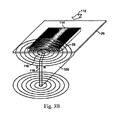
- Fig. 3B is a simplified perspective view of an apparatus in accordance with Fig. 3A.
- the substrate 29 moves across the magnet 106 in the direction of the arrow.
- the image 110 forms a rolling bar feature 114, which will appear to move up and down as the image is tilted or the viewing angle is changed.
- the flakes 26 are shown as being tilted in relation to the magnetic field lines.
- the image is typically very thin, and the flakes might not form a hump, as illustrated, but generally align along the magnetic field lines to provide the desired arched reflective properties to create a rolling bar effect.
- the bar appeared to roll up and down the image when tilted through an angle of about 25 degrees in one example.
- the intensity of the rolling bar effect could be enhanced by chamfering 116 the trailing edge 118 of the magnet. It is believed that this gradually reduces the magnetic field as the image clears the magnet. Otherwise, the magnetic transition occurring at a sharp corner of the magnet might re-arrange the orientation of the flakes and degrade the visual effect of the rolling bar. In a particular embodiment, the corner of the magnet was chamfered at an angle of thirty degrees from the plane of the substrate.
- An alternative approach is to fix the flakes before they pass over the trailing edge of the magnet. This could be done by providing a UV source part way down the run of the magnet, for UV-curing carrier, or a drying source for evaporative carriers, for example.
- FIG. 5A an image in the form of a 4 sided outline or closed region is shown wherein the top side is curved downward. It is interesting to note that upon looking at this figure, there is no particular association with an image made and it is not recognizable as a common object; it is merely a 2-D polygon. On the other hand, upon viewing, Fig. 5B having the same outline and the same flakes but oriented differently an association with a known common recognizable object, a cylinder is made. By providing a large rolling bar that spans the region the rolling bar adds shading so that the user perceives depth and three-dimensionality. In addition to this by tilting the image in Fig.
- Figs. 6 and 7 show rolling bars in two other shapes wherein the rolling bar provides a perception of depth, movement, and wherein the actual area of the bar varies as it sweeps the image.
- a shield comprising an outline having magnetically oriented pigment flakes disposed therein, oriented in the form of a rolling bar having a large radius of curvature. It is important to select a radius of curvature that will provide an expected sense of depth and curvature to most closely represent the image that is created.
- the presence of a rolling bar provides a perceived change in area of the rolling bar as the image is tilted and the bar appears to move across the image. This phenomenon is quite striking and is illustrated by the sequence of figures 14A through 14D. These figures are of the same image tilted at different angles, with an increasing angle in each subsequent figure with Fig. 14A being at normal incidence.
- a circle is shown having a rolling bar spanning its diameter.
- the circle in the absence of the rolling bar is merely what the viewer perceives as a circle, however the presence of the rolling bar provides the viewer with the illusion that the object is a sphere.
- movement is not shown in the figure, the viewer witnessing the bar rolling along the circle apparently becoming smaller as the image is tilted and the bar moves toward the left, give the viewer a sense of three dimensionality and realism.
- this kinematical image provides the viewer with the experience of the light and shadows moving across the ball as the image is tilted.
- the view has the perception of moving around the object or the viewed object being rotated.
- the viewer since the area of the bar decreases as it moves to the left the viewer has the perception that this object is more than just a picture or photograph. It is for all intents and purposes a flat image however the viewer perceives depth and movement and an enhanced viewing experience in contrast to viewing a "normal" image. It has three dimensionality, movement and change of shape that occurs when viewing and tilting the object.
- Fig. 7 the area of the rolling bar shown by highlights in the centre fading off to dark regions toward the sides, as it appears to sweep across the image has a substantially uniform area, however, the bar appears to follow the curved trajectory of the upper and lower walls as it fills the outline and appears to project out of the page, moving from a lower central position to an upper right most or left most position as it rises.
- Fig. 8A an alternative embodiment of the invention is shown wherein two rolling bars are designed to move oppositely simultaneously when the image is tiled in one direction; for example toward the right pointing arrow, about a longitudinal axis of one of the rolling bars.
- FIGs. 8B and 8C an image with a "double rolling bar” is shown, wherein one portion 44' has magnetic flakes oriented in convex fashion while another portion 44"of the image has magnetic flakes oriented in a concave orientation.
- the "rolling bar” magnet is placed underneath the paper substrate.
- the magnet is placed above the paper substrate.
- a "Double tilt" image is formed when magnetic flakes in two regions of the image have differing and opposing orientation, for example, +30 degrees and -30 degrees. At one tilted position of the printed image one part of the image is dark and another part is light.
- the areas switch their light and dark regions so that the first image becomes light and the second image becomes dark.
- this switch of the light and dark may occur from the top to the bottom and back, as well as from the left to the right and back, in dependence upon the on orientation of the flakes.
- the bright bar 44' appears to have "moved” to a second position in the image, and the sizes of the contrasting fields 46', 48' have changed; furthermore the bright bar 44" appears to have "moved” to a different position in the image, and the sizes of the contrasting fields 46", 48" have changed.
- Figs. 15B through 15D the "liberty bell" is shown.
- Fig. 15A the image is shown at a normal angle of incidence.
- Figs 15B through 15D the same print is shown tiled at different angles of incidence as indicated by arrows about the axis.
- the rolling bar 150 shown if Fig. 15B, having a large radius of curvature appears to shift to the left when viewing Fig. 15C, and the smaller concave inverted rolling bar 152 on the inside surface of the bell, appears to move oppositely, to the left.
- Fig. 15B having a large radius of curvature appears to shift to the left when viewing Fig. 15C
- the smaller concave inverted rolling bar 152 on the inside surface of the bell appears to move oppositely, to the left.
- 15D illustrates an opposite perceived movement, wherein the larger bar 150 when tilted oppositely shows the large bar 150 appearing to shift to the right while the smaller bar 152 simultaneously appears to roll to the left.
- This behaviour of the light incident upon the image mimics a real lighting situation on a real object such as the liberty bell. The lighting shifts simultaneously and oppositely in different regions as one would expect from a real object.
- the illusion is designed to follow the physics of natural light on the real object.
- the illusion is that the image is real. Turning now to Fig.
- the four elements 154a, 154b, 154c, and 154d, that comprise the bell are shown separately, for ease of understanding, and each of these is printed, one at a time, in the correct location upon the substrate to form the image shown in Fig. 15A.
- the image is formed by printing each region and applying the magnets to form flakes aligned in oppositely arching patterns to create the two rolling bars, a sequenced automated printed process could be used to produce this and similar images.
- Fig. 16F is a printed image of a hemisphere wherein the entire image is coated with alignable pigment flakes. After alignment of flakes as will be explained, the hemisphere is formed.
- the printed image of the hemisphere shown in Fig. 16F appears as the image shown in Fig. 16G as the substrate is tilted or the light source varied. As the image is tilted from the normal to the left about a vertical axis through the centre, the bright hemisphere which appears much like a ball, rolls with a change of tilt angle.
- the hemisphere in Fig. 16F is capable or appearing to move in any x-y direction, depending upon the angle of tilt.
- tilting the image about the x or y axis results in the appearance of movement.
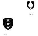
- the shield in Fig. 16J uses a combination of a rolling bar and hemisphere effects to provide very interesting combination of effects wherein the shield and hemisphere appear to project out of the page.
- This is produced in a two stage process, wherein the substrate is first coated with a magnetic coating and a hemisphere is formed and cured as in Fig. 16H.
- a second coating is applied through a mask or stencil to form the coating of Fig. 161 ensuring that no additional coating material covers the hemisphere.
- This second coating is placed in a magnetic field so as to produce a rolling bar.
- the method of forming the dynamic or kinematic hemispherical image described above is more complex than the method of forming the rolling bar.
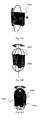
- the magnet 160a shown in Fig. 16A illustrates a field line above and below the magnet, forming two loops.
- This diagram purposely only shows these two lines, however, there is essentially a front of lines that would be generated parallel to these lines, spanning the entire magnet.
- the magnets 160a, 160b used to create the hemisphere are more complex as is shown in Fig. 16B and more particularly in 16C. Part of the magnet in Fig. 16B is cut away to illustrate some of the field lines.
- the field extending above the cluster of magnets 160a, 160b, 160c is dome shaped, as is the magnetic field extending below.
- a print of a hemispherical kinematic image is formed as in Fig. 16D or 16E by disposing the coated substrate 167 with fluid ink in the dome shaped magnetic field, just above the magnets as shown in Fig. 16D or with greater separation from the magnets and supported toward the middle of the field while the magnets are spinning.
- the velocity at which the magnets or image are relatively rotated is approximately 120 rpm.
- the image is then removed from the region of the field and is cured.
- the rotation velocity of the magnets can be slower or faster than 120 rpm, depending on the particles magnetic properties and viscosity of the ink vehicle. If the velocity is too slow however, the quality of the image will degrade.
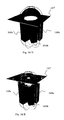
- Fig. 17A is an illustration of an alternative embodiment similar but inverted to the image shown in Fig. 16F.
- a simulated magnetic field from a hemispherical magnet is shown in Fig. 17A. This is the shape of the field that created the image shown in Fig. 17C.
- the North pole of the magnet is on the top and the particles are aligned concentrically in a funnel-like fashion.
- the field 194 in Fig. 17B is shown and flakes 193 in a carrier 192 disposed upon substrate 191 are aligned in a funnel like orientation following the field lines.
- this field generated a bright kinematic spot 192 in the middle of the image 191; and the funnel-like alignment of flakes generated a dark kinematic spot in the middle of the image.
- the fields shown and described are formed from permanent magnets, electric fields or electromagnetic fields can be used in many embodiments.
- the field and the particles must be compatible so that the particles are capable of being oriented by the particular field.
Landscapes
- Business, Economics & Management (AREA)
- Accounting & Taxation (AREA)
- Finance (AREA)
- Physics & Mathematics (AREA)
- General Physics & Mathematics (AREA)
- Engineering & Computer Science (AREA)
- Theoretical Computer Science (AREA)
- Printing Methods (AREA)
- Inks, Pencil-Leads, Or Crayons (AREA)
- Credit Cards Or The Like (AREA)
- Toys (AREA)
Applications Claiming Priority (2)
| Application Number | Priority Date | Filing Date | Title |
|---|---|---|---|
| US11/022,106 US7517578B2 (en) | 2002-07-15 | 2004-12-22 | Method and apparatus for orienting magnetic flakes |
| US11/313,165 US7604855B2 (en) | 2002-07-15 | 2005-12-20 | Kinematic images formed by orienting alignable flakes |
Publications (3)
| Publication Number | Publication Date |
|---|---|
| EP1674282A2 true EP1674282A2 (de) | 2006-06-28 |
| EP1674282A3 EP1674282A3 (de) | 2011-02-23 |
| EP1674282B1 EP1674282B1 (de) | 2013-06-12 |
Family
ID=36602315
Family Applications (1)
| Application Number | Title | Priority Date | Filing Date |
|---|---|---|---|
| EP05028190.6A Expired - Lifetime EP1674282B1 (de) | 2004-12-22 | 2005-12-22 | Kinematisches Bild durch Orientierung ausrichtbarer Pigmentflocken |
Country Status (8)
| Country | Link |
|---|---|
| US (1) | US7604855B2 (de) |
| EP (1) | EP1674282B1 (de) |
| JP (1) | JP5117195B2 (de) |
| KR (1) | KR101319514B1 (de) |
| CN (4) | CN107185788B (de) |
| AU (2) | AU2005319097B2 (de) |
| CA (1) | CA2588380C (de) |
| WO (1) | WO2006069218A2 (de) |
Cited By (15)
| Publication number | Priority date | Publication date | Assignee | Title |
|---|---|---|---|---|
| EP1878585A1 (de) | 2006-07-12 | 2008-01-16 | JDS Uniphase Corporation | Stempelung einer Beschichtung aus gehärteten feldausgerichteten Spezialeffektspänen und daraus erzeugtes Bild |
| US7550197B2 (en) | 2003-08-14 | 2009-06-23 | Jds Uniphase Corporation | Non-toxic flakes for authentication of pharmaceutical articles |
| WO2009092984A1 (en) * | 2008-01-23 | 2009-07-30 | De La Rue International Limited | Optically variable magnetic stripe assembly |
| US7625632B2 (en) | 2002-07-15 | 2009-12-01 | Jds Uniphase Corporation | Alignable diffractive pigment flakes and method and apparatus for alignment and images formed therefrom |
| US7645510B2 (en) | 2002-09-13 | 2010-01-12 | Jds Uniphase Corporation | Provision of frames or borders around opaque flakes for covert security applications |
| US7674501B2 (en) | 2002-09-13 | 2010-03-09 | Jds Uniphase Corporation | Two-step method of coating an article for security printing by application of electric or magnetic field |
| WO2011092502A2 (en) | 2010-02-01 | 2011-08-04 | De La Rue International Limited | Security elements and methods and apparatus for their manufacture |
| US8025952B2 (en) | 2002-09-13 | 2011-09-27 | Jds Uniphase Corporation | Printed magnetic ink overt security image |
| CN110143076A (zh) * | 2019-05-28 | 2019-08-20 | 成都印钞有限公司 | 一种磁性光变油墨的定磁方法 |
| US10500889B2 (en) | 2014-07-30 | 2019-12-10 | Sicpa Holding Sa | Belt-driven processes for producing optical effect layers |
| US10933442B2 (en) | 2013-12-13 | 2021-03-02 | Sicpa Holding Sa | Processes for producing effects layers |
| US11691449B2 (en) | 2018-01-17 | 2023-07-04 | Sicpa Holding Sa | Processes for producing optical effects layers |
| US11823003B2 (en) | 2019-02-28 | 2023-11-21 | Sicpa Holding Sa | Method for authenticating a magnetically induced mark with a portable device |
| US12311406B2 (en) | 2021-03-31 | 2025-05-27 | Sicpa Holding Sa | Methods for producing optical effect layers comprising magnetic or magnetizable pigment particles and exhibiting one or more indicia |
| US12458999B2 (en) | 2020-05-26 | 2025-11-04 | Sicpa Holding Sa | Magnetic assemblies and methods for producing optical effect layers comprising oriented platelet-shaped magnetic or magnetizable pigment particles |
Families Citing this family (63)
| Publication number | Priority date | Publication date | Assignee | Title |
|---|---|---|---|---|
| US7047883B2 (en) | 2002-07-15 | 2006-05-23 | Jds Uniphase Corporation | Method and apparatus for orienting magnetic flakes |
| US11230127B2 (en) | 2002-07-15 | 2022-01-25 | Viavi Solutions Inc. | Method and apparatus for orienting magnetic flakes |
| US7934451B2 (en) * | 2002-07-15 | 2011-05-03 | Jds Uniphase Corporation | Apparatus for orienting magnetic flakes |
| US9164575B2 (en) | 2002-09-13 | 2015-10-20 | Jds Uniphase Corporation | Provision of frames or borders around pigment flakes for covert security applications |
| US20070224398A1 (en) * | 2006-03-21 | 2007-09-27 | Jds Uniphase Corporation | Brand Protection Label With A Tamper Evident Abrasion-Removable Magnetic Ink |
| US9458324B2 (en) | 2002-09-13 | 2016-10-04 | Viava Solutions Inc. | Flakes with undulate borders and method of forming thereof |
| CA2523648C (en) * | 2004-10-20 | 2014-05-13 | Jds Uniphase Corporation | Alignment of paste-like ink having magnetic particles therein, and the printing of optical effects |
| CA2541568C (en) | 2005-04-06 | 2014-05-13 | Jds Uniphase Corporation | Dynamic appearance-changing optical devices (dacod) printed in a shaped magnetic field including printable fresnel structures |
| CA2568274C (en) | 2005-11-18 | 2014-08-12 | Jds Uniphase Corporation | Magnetic plate for printing of optical effects |
| US10343436B2 (en) | 2006-02-27 | 2019-07-09 | Viavi Solutions Inc. | Security device formed by printing with special effect inks |
| DE102006057507A1 (de) * | 2006-12-06 | 2008-06-12 | Merck Patent Gmbh | Optisch variables Sicherheitselement |
| AU2008219354B2 (en) | 2007-09-19 | 2014-02-13 | Viavi Solutions Inc. | Anisotropic magnetic flakes |
| US20090123699A1 (en) | 2007-11-09 | 2009-05-14 | Motorola, Inc. | Viewable surface having unnoticeable smudges |
| JP2009193069A (ja) | 2008-02-13 | 2009-08-27 | Jds Uniphase Corp | 光学的な特殊効果フレークを含むレーザ印刷用の媒体 |
| FR2942244B1 (fr) * | 2009-02-16 | 2011-04-15 | Arjowiggins Security | Procede pour creer une animation visuelle sur un support |
| JP5570305B2 (ja) * | 2009-11-06 | 2014-08-13 | 富士フイルム株式会社 | 熱線遮蔽材 |
| AU2015200595B2 (en) * | 2010-02-01 | 2016-08-18 | De La Rue International Limited | Security elements and methods and apparatus for their manufacture |
| US20130270344A1 (en) * | 2010-12-21 | 2013-10-17 | Merck Patent Gmbh | Coloured magnetisable security element |
| ES2584629T3 (es) | 2010-12-27 | 2016-09-28 | Viavi Solutions Inc. | Sistema y método para formar una imagen sobre un substrato |
| PL2484455T3 (pl) * | 2011-02-07 | 2015-05-29 | Sicpa Holding Sa | Urządzenie przedstawiające dynamiczny wizualny efekt ruchu i sposób jego wytwarzania |
| US8616461B2 (en) * | 2011-07-13 | 2013-12-31 | Eastman Kodak Company | Printed dynamic optical illusion images |
| US8616460B2 (en) * | 2011-07-13 | 2013-12-31 | Eastman Kodak Company | Method for providing dynamic optical illusion images |
| EP4043231B1 (de) * | 2012-01-12 | 2025-04-30 | Viavi Solutions Inc. | Verfahren zur herstellung eines artikels mit ausgerichteten pigmentplättchen |
| US11073959B2 (en) * | 2012-06-08 | 2021-07-27 | Apple Inc. | Simulating physical materials and light interaction in a user interface of a resource-constrained device |
| WO2014086715A1 (de) * | 2012-12-04 | 2014-06-12 | Sectago Gmbh | Sicherheitseinrichtung |
| TW201431616A (zh) | 2013-01-09 | 2014-08-16 | Sicpa Holding Sa | 顯示取決於視角的光學效應之光學效應層;用於其生產之工藝和裝置;攜帶光學效應層之物品;及其用途 |
| CA2890164C (en) * | 2013-01-09 | 2023-01-10 | Sicpa Holding Sa | Optical effect layers showing a viewing angle dependent optical effect; processes and devices for their production; items carrying an optical effect layer; and uses thereof |
| US8789925B1 (en) | 2013-02-01 | 2014-07-29 | Xerox Corporation | Method and apparatus for printing of magnetic inks |
| DE102013002137A1 (de) * | 2013-02-07 | 2014-08-07 | Giesecke & Devrient Gmbh | Optisch variables Flächenmuster |
| JP6550338B2 (ja) * | 2013-02-12 | 2019-07-24 | ゼクタゴ ゲーエムベーハー | セキュリティ装置 |
| WO2014177448A1 (en) * | 2013-05-02 | 2014-11-06 | Sicpa Holding Sa | Processes for producing security threads or stripes |
| TWI641660B (zh) | 2013-08-05 | 2018-11-21 | 瑞士商西克帕控股有限公司 | 磁性或可磁化色料顆粒及光學效應層 |
| US10207531B2 (en) * | 2013-12-02 | 2019-02-19 | SECTAG GmbH | Security device |
| RU2641864C2 (ru) | 2013-12-11 | 2018-01-22 | Сикпа Холдинг Са | Оптически изменяющиеся защитные нити и полоски |
| US10023000B2 (en) * | 2014-02-13 | 2018-07-17 | Sicpa Holding Sa | Security threads and stripes |
| FR3019496A1 (fr) * | 2014-04-07 | 2015-10-09 | Hologram Ind | Composant optique de securite a effet reflectif, fabrication d'un tel composant et document securise equipe d'un tel composant |
| PT2965920T (pt) | 2014-07-09 | 2018-01-16 | Sicpa Holding Sa | Listras e filetes de segurança magnéticos oticamente variáveis |
| DE102015005911A1 (de) * | 2015-05-07 | 2016-11-10 | Giesecke & Devrient Gmbh | Optisch variables Sicherheitselement |
| DE102015005969A1 (de) * | 2015-05-08 | 2016-11-10 | Giesecke & Devrient Gmbh | Optisch variables Sicherheitselement |
| TWI709626B (zh) * | 2015-10-15 | 2020-11-11 | 瑞士商西克帕控股有限公司 | 用於製造包含定向非球面磁性或可磁化顏料顆粒的光學效應層之磁性組件與製程 |
| PL3374093T3 (pl) | 2015-11-10 | 2020-06-01 | Sicpa Holding Sa | Przyrządy i sposoby do wytwarzania warstw z efektem optycznym zawierających zorientowane niesferyczne magnetyczne lub magnesowalne cząstki pigmentu |
| AR107681A1 (es) | 2016-02-29 | 2018-05-23 | Sicpa Holding Sa | Aparatos y procesos para producir capas con efecto óptico que comprenden partículas de pigmento no esféricas orientadas magnéticas, o magnetizables |
| EP3178569A1 (de) | 2016-06-29 | 2017-06-14 | Sicpa Holding Sa | Verfahren und vorrichtungen zur erzeugung optischer effektschichten mit einer photomaske |
| CA3034898C (en) * | 2016-08-31 | 2022-02-01 | Viavi Solutions Inc. | Orienting magnetically-orientable flakes |
| KR102612114B1 (ko) | 2016-08-31 | 2023-12-11 | 비아비 솔루션즈 아이엔씨. | 각져 있는 반사성 세그먼트를 갖는 물품 |
| US10357991B2 (en) | 2016-12-19 | 2019-07-23 | Viavi Solutions Inc. | Security ink based security feature |
| EP3421551A1 (de) | 2017-06-28 | 2019-01-02 | Andres Ruiz Quevedo | Effektpigment |
| TWI768096B (zh) * | 2017-08-25 | 2022-06-21 | 瑞士商西克帕控股有限公司 | 光學效果層、用於產生此光學效果層的裝置及進程、及此裝置的使用方法 |
| DE102018000385A1 (de) | 2018-01-18 | 2019-07-18 | Giesecke+Devrient Currency Technology Gmbh | Einstellungsmagnet für die Herstellung von Sicherheitselementen mit magnetisch orientierten Effektpigmenten und Herstellverfahren für solche Einstellmagnete |
| US10618340B2 (en) | 2018-05-16 | 2020-04-14 | Viavi Solutions Inc. | Security feature based on a single axis alignment of mirrors in a structured surface that forms a micro mirror array |
| US10642214B2 (en) | 2018-08-13 | 2020-05-05 | Viavi Solutions Inc. | Optical security device based on a surface of revolution |
| DE102018008146A1 (de) * | 2018-10-15 | 2020-04-16 | Giesecke+Devrient Currency Technology Gmbh | Sicherheitselement mit Mikroreflektoren zur perspektivischen Darstellung eines Motivs |
| IL285790B2 (en) | 2019-02-28 | 2024-06-01 | Sicpa Holding Sa | Verifiable access certificate |
| CN111776471B (zh) * | 2019-08-16 | 2022-07-12 | 西安印钞有限公司 | 一种景变防伪结构和防伪塑封及制备方法 |
| WO2021072105A1 (en) | 2019-10-08 | 2021-04-15 | Viavi Solutions Inc. | Security pigment and optical security element |
| KR102788934B1 (ko) * | 2019-12-06 | 2025-03-31 | 삼성디스플레이 주식회사 | 발광 소자의 정렬 방법, 이를 이용한 표시 장치의 제조 방법 및 표시 장치 |
| CN111645411B (zh) * | 2020-05-13 | 2022-07-26 | 惠州市华阳光学技术有限公司 | 磁定向装置和印刷设备 |
| US12152152B2 (en) | 2020-06-05 | 2024-11-26 | Viavi Solutions Inc. | Security pigment |
| BR112022025995A2 (pt) | 2020-06-23 | 2023-01-17 | Sicpa Holding Sa | Métodos para produzir camadas de efeito óptico que compreendem partículas de pigmento magnéticas ou magnetizáveis |
| AR123351A1 (es) * | 2020-09-02 | 2022-11-23 | Sicpa Holding Sa | Documentos o artículos de seguridad que comprenden capas de efecto óptico que comprenden partículas de pigmento magnéticas o magnetizables y métodos para producir dichas capas de efecto óptico |
| AU2023224380A1 (en) | 2022-02-28 | 2024-10-10 | Sicpa Holding Sa | Methods for producing optical effect layers comprising magnetic or magnetizable pigment particles and exhibiting one or more indicia |
| AU2023317785A1 (en) | 2022-08-05 | 2025-03-13 | Sicpa Holding Sa | Methods for producing optical effect layers comprising magnetic or magnetizable pigment particles and exhibiting one or more indicia |
| TW202528492A (zh) | 2023-08-24 | 2025-07-16 | 瑞士商西克帕控股有限公司 | 包含磁性或可磁化顏料顆粒之uv-vis輻射可固化塗料組成物及用於製造光學效應層之方法 |
Citations (3)
| Publication number | Priority date | Publication date | Assignee | Title |
|---|---|---|---|---|
| US20030190473A1 (en) | 2002-04-05 | 2003-10-09 | Flex Products, Inc. | Chromatic diffractive pigments and foils |
| WO2004007095A2 (en) | 2002-07-15 | 2004-01-22 | Jds Uniphase Corporation | Method and apparatus for orienting magnetic flakes and image obtained by said method |
| US6692830B2 (en) | 2001-07-31 | 2004-02-17 | Flex Products, Inc. | Diffractive pigment flakes and compositions |
Family Cites Families (108)
| Publication number | Priority date | Publication date | Assignee | Title |
|---|---|---|---|---|
| US2570856A (en) * | 1947-03-25 | 1951-10-09 | Du Pont | Process for obtaining pigmented films |
| NL131828C (de) * | 1961-05-04 | |||
| DE1253730B (de) | 1964-06-05 | 1967-11-09 | Agfa Ag | Verfahren zum ganzen oder auszugsweisen Abdruck einer Druckform und Rotationsvervielfaelfaeltiger zur Durchfuehrung des Verfahrens |
| FR1440147A (fr) | 1965-04-15 | 1966-05-27 | Tefal Sa | Procédé de décoration, dans la masse, d'un matériau plastique translucide |
| US3627580A (en) * | 1969-02-24 | 1971-12-14 | Eastman Kodak Co | Manufacture of magnetically sensitized webs |
| US3845499A (en) * | 1969-09-25 | 1974-10-29 | Honeywell Inc | Apparatus for orienting magnetic particles having a fixed and varying magnetic field component |
| US3633720A (en) * | 1969-09-25 | 1972-01-11 | Honeywell Inc | Alphanumeric printing device employing magnetically positionable particles |
| US3610721A (en) * | 1969-10-29 | 1971-10-05 | Du Pont | Magnetic holograms |
| US3676273A (en) * | 1970-07-30 | 1972-07-11 | Du Pont | Films containing superimposed curved configurations of magnetically orientated pigment |
| US3853676A (en) * | 1970-07-30 | 1974-12-10 | Du Pont | Reference points on films containing curved configurations of magnetically oriented pigment |
| IT938725B (it) * | 1970-11-07 | 1973-02-10 | Magnetfab Bonn Gmbh | Procedimento e dispositivo per otte nere disegni in strati superficiali per mezzo di campi magnetici |
| US3790407A (en) * | 1970-12-28 | 1974-02-05 | Ibm | Recording media and method of making |
| US3873975A (en) * | 1973-05-02 | 1975-03-25 | Minnesota Mining & Mfg | System and method for authenticating and interrogating a magnetic record medium |
| US4054992A (en) * | 1974-05-30 | 1977-10-25 | Weed Eater, Inc. | Rotary cutting assembly |
| DE2520581C3 (de) * | 1975-05-09 | 1980-09-04 | Kienzle Apparate Gmbh, 7730 Villingen-Schwenningen | Anordnung zum loschbaren Aufzeichnen von Meßgrößen |
| US4011009A (en) * | 1975-05-27 | 1977-03-08 | Xerox Corporation | Reflection diffraction grating having a controllable blaze angle |
| US4099838A (en) * | 1976-06-07 | 1978-07-11 | Minnesota Mining And Manufacturing Company | Reflective sheet material |
| DE2752895A1 (de) * | 1976-12-06 | 1978-06-08 | Emi Ltd | Verfahren zur herstellung einer materialschicht, deren oberflaeche ein abtastbares muster aufweist, sowie sicherheitsdokumentensystem |
| FR2408890A1 (fr) * | 1977-11-10 | 1979-06-08 | Transac Dev Transact Automat | Procede et dispositif d'orientation et de fixation dans une direction determinee de particules magnetiques contenues dans une encre polymerisable |
| US4271782A (en) * | 1978-06-05 | 1981-06-09 | International Business Machines Corporation | Apparatus for disorienting magnetic particles |
| US4398798A (en) * | 1980-12-18 | 1983-08-16 | Sperry Corporation | Image rotating diffraction grating |
| US4543551A (en) * | 1984-07-02 | 1985-09-24 | Polaroid Corporation | Apparatus for orienting magnetic particles in recording media |
| US4788116A (en) | 1986-03-31 | 1988-11-29 | Xerox Corporation | Full color images using multiple diffraction gratings and masking techniques |
| DE3617430A1 (de) * | 1986-05-23 | 1987-11-26 | Merck Patent Gmbh | Perlglanzpigmente |
| JPH0694543B2 (ja) | 1987-01-09 | 1994-11-24 | 三菱自動車工業株式会社 | 塗 料 |
| WO1988007214A1 (en) | 1987-03-10 | 1988-09-22 | Precis (549) Limited | Light reflective materials |
| US4798116A (en) * | 1987-09-04 | 1989-01-17 | Silver Marc L | Document shredding machine |
| JP2514828B2 (ja) * | 1988-01-18 | 1996-07-10 | 富士写真フイルム株式会社 | 磁気記録媒体の製造方法 |
| US5186787A (en) * | 1988-05-03 | 1993-02-16 | Phillips Roger W | Pre-imaged high resolution hot stamp transfer foil, article and method |
| US4838648A (en) | 1988-05-03 | 1989-06-13 | Optical Coating Laboratory, Inc. | Thin film structure having magnetic and color shifting properties |
| JPH0298811A (ja) * | 1988-10-05 | 1990-04-11 | Fuji Photo Film Co Ltd | 磁気記録媒体 |
| US5079058A (en) * | 1989-03-03 | 1992-01-07 | Kansai Paint Co., Ltd. | Patterned film forming laminated sheet |
| US5192611A (en) * | 1989-03-03 | 1993-03-09 | Kansai Paint Co., Ltd. | Patterned film forming laminated sheet |
| KR0135274B1 (ko) | 1989-06-27 | 1998-04-22 | 사사끼 가즈오 | 모양 도장막 형성 방법 |
| DE3938055A1 (de) * | 1989-11-16 | 1991-05-23 | Merck Patent Gmbh | Mit plaettchenfoermigen pigmenten beschichtete materialien |
| US5177344A (en) * | 1990-10-05 | 1993-01-05 | Rand Mcnally & Company | Method and appparatus for enhancing a randomly varying security characteristic |
| EP0556449B1 (de) | 1992-02-21 | 1997-03-26 | Hashimoto Forming Industry Co., Ltd. | Lackierung mit magnetisch hergestelltem Muster und lackiertes Produkt mit magnetisch hergestelltem Muster |
| JP2774015B2 (ja) * | 1992-04-10 | 1998-07-09 | 橋本フォーミング工業株式会社 | 車両用ホィールカバー及びその製造方法 |
| JP2857276B2 (ja) * | 1992-02-21 | 1999-02-17 | 橋本フォーミング工業株式会社 | 磁気塗装 |
| JPH05337436A (ja) * | 1992-06-11 | 1993-12-21 | Hashimoto Forming Ind Co Ltd | 所定形状の模様を有する成形品及びこの成形品の製造方法 |
| DE4212290C2 (de) | 1992-02-29 | 1996-08-01 | Kurz Leonhard Fa | Wertdokument |
| DE69303651T2 (de) * | 1992-03-13 | 1997-01-02 | Fuji Photo Film Co Ltd | Magnetischer Aufzeichnungsträger und Verfahren zu seiner Herstellung |
| US5672410A (en) * | 1992-05-11 | 1997-09-30 | Avery Dennison Corporation | Embossed metallic leafing pigments |
| US5991078A (en) * | 1992-08-19 | 1999-11-23 | Dai Nippon Printing Co., Ltd. | Display medium employing diffraction grating and method of producing diffraction grating assembly |
| JP2655551B2 (ja) * | 1992-09-09 | 1997-09-24 | 工業技術院長 | 微細表面形状創成法 |
| TW400952U (en) * | 1993-04-06 | 2000-08-01 | Commw Scient Ind Res Org | Optical data element |
| WO1995002838A1 (en) * | 1993-07-16 | 1995-01-26 | Luckoff Display Corporation | Diffractive display utilizing reflective or transmissive light yielding single pixel full color capability |
| US6033782A (en) * | 1993-08-13 | 2000-03-07 | General Atomics | Low volume lightweight magnetodielectric materials |
| EP0644508B1 (de) * | 1993-08-31 | 1999-12-22 | Control Module, Inc. | Gesichertes optisches Identifikationsverfahren und die hierzu erforderlichen Mittel |
| DE4335308C2 (de) * | 1993-10-16 | 1995-12-14 | Daimler Benz Ag | Kennzeichnung von Fahrzeugen zur Erschwerung von Diebstahl und oder unbefugter Veräußerung |
| US5415950A (en) | 1993-11-08 | 1995-05-16 | E. I. Du Pont De Nemours And Company | Holographic flake pigment |
| US5424119A (en) * | 1994-02-04 | 1995-06-13 | Flex Products, Inc. | Polymeric sheet having oriented multilayer interference thin film flakes therein, product using the same and method |
| KR100362350B1 (ko) * | 1994-03-16 | 2003-02-19 | 오브이디 키네그람 악티엔게젤샤프트 | 광학표지를지닌정보캐리어 |
| DE4439455A1 (de) | 1994-11-04 | 1996-05-09 | Basf Ag | Verfahren zur Herstellung von dreidimensionale optische Effekte aufweisenden Beschichtungen |
| EP0861156B1 (de) * | 1995-11-13 | 2000-04-26 | Orell Füssli Banknote Engineering Ltd. | Sicherheitsdokument mit sicherheitsmarkierung |
| GB9524862D0 (en) * | 1995-12-06 | 1996-02-07 | The Technology Partnership Plc | Colour diffractive structure |
| AUPO728397A0 (en) * | 1997-06-11 | 1997-07-03 | Securency Pty Ltd | Security document including a magnetic watermark and method of production thereof |
| US6103361A (en) * | 1997-09-08 | 2000-08-15 | E. I. Du Pont De Nemours And Company | Patterned release finish |
| US6168100B1 (en) * | 1997-10-23 | 2001-01-02 | Toyota Jidosha Kabushiki Kaisha | Method for producing embossed metallic flakelets |
| US6549131B1 (en) | 1999-10-07 | 2003-04-15 | Crane & Co., Inc. | Security device with foil camouflaged magnetic regions and methods of making same |
| EP0953937A1 (de) | 1998-04-30 | 1999-11-03 | Securency Pty. Ltd. | Sicherheitselement zur Verhinderung der Fälschung von Wertpapieren |
| EP0978373B1 (de) | 1998-08-06 | 2011-10-12 | Sicpa Holding Sa | Anorganische Folie zur Herstellung von Pigmenten |
| US6576155B1 (en) | 1998-11-10 | 2003-06-10 | Biocrystal, Ltd. | Fluorescent ink compositions comprising functionalized fluorescent nanocrystals |
| US6643001B1 (en) | 1998-11-20 | 2003-11-04 | Revco, Inc. | Patterned platelets |
| US6150022A (en) * | 1998-12-07 | 2000-11-21 | Flex Products, Inc. | Bright metal flake based pigments |
| US6692031B2 (en) * | 1998-12-31 | 2004-02-17 | Mcgrew Stephen P. | Quantum dot security device and method |
| US7517578B2 (en) | 2002-07-15 | 2009-04-14 | Jds Uniphase Corporation | Method and apparatus for orienting magnetic flakes |
| US6761959B1 (en) | 1999-07-08 | 2004-07-13 | Flex Products, Inc. | Diffractive surfaces with color shifting backgrounds |
| US6987590B2 (en) * | 2003-09-18 | 2006-01-17 | Jds Uniphase Corporation | Patterned reflective optical structures |
| US7667895B2 (en) * | 1999-07-08 | 2010-02-23 | Jds Uniphase Corporation | Patterned structures with optically variable effects |
| US6545809B1 (en) * | 1999-10-20 | 2003-04-08 | Flex Products, Inc. | Color shifting carbon-containing interference pigments |
| US6649256B1 (en) * | 2000-01-24 | 2003-11-18 | General Electric Company | Article including particles oriented generally along an article surface and method for making |
| US6554044B2 (en) * | 2000-01-28 | 2003-04-29 | Fargo Electronics Inc. | Laminator peel-off bar |
| US6310720B1 (en) * | 2000-06-02 | 2001-10-30 | Genoa Corporation | Polarization insensitive semiconductor optical amplifier |
| DE10032128A1 (de) * | 2000-07-05 | 2002-01-17 | Giesecke & Devrient Gmbh | Sicherheitspapier und daraus hergestelltes Wertdokument |
| US6586098B1 (en) * | 2000-07-27 | 2003-07-01 | Flex Products, Inc. | Composite reflective flake based pigments comprising reflector layers on bothside of a support layer |
| DE10044465A1 (de) * | 2000-09-08 | 2002-03-21 | Giesecke & Devrient Gmbh | Datenträger mit einem optisch variablen Element |
| US6686027B1 (en) * | 2000-09-25 | 2004-02-03 | Agra Vadeko Inc. | Security substrate for documents of value |
| JP2002200871A (ja) * | 2000-10-24 | 2002-07-16 | Konica Corp | 画像記録体、画像記録体形成方法及び画像記録体を用いた認証識別方法 |
| US6565770B1 (en) | 2000-11-17 | 2003-05-20 | Flex Products, Inc. | Color-shifting pigments and foils with luminescent coatings |
| US6572784B1 (en) | 2000-11-17 | 2003-06-03 | Flex Products, Inc. | Luminescent pigments and foils with color-shifting properties |
| US20020110672A1 (en) * | 2001-02-12 | 2002-08-15 | Joanne Muratore-Pallatino | Cosmetic skin tattoo |
| EP1239307A1 (de) | 2001-03-09 | 2002-09-11 | Sicpa Holding S.A. | Magnetische Dünnschicht-Interferenz-Vorrichtung |
| DE10114445A1 (de) * | 2001-03-23 | 2002-09-26 | Eckart Standard Bronzepulver | Weicheisenpigmente |
| DE60214153T2 (de) * | 2001-04-24 | 2007-07-12 | Merck Patent Gmbh | Doppelbrechende markierung |
| US20020160194A1 (en) * | 2001-04-27 | 2002-10-31 | Flex Products, Inc. | Multi-layered magnetic pigments and foils |
| US6808806B2 (en) * | 2001-05-07 | 2004-10-26 | Flex Products, Inc. | Methods for producing imaged coated articles by using magnetic pigments |
| ITMO20010084A1 (it) * | 2001-05-08 | 2002-11-08 | G S Srl Unipersonale | Metodo per realizzare la lettura di frazioni dell'intervallo tra gli elementi fotosensibili o pixel contigui di un sensore ottico lineare |
| US7625632B2 (en) * | 2002-07-15 | 2009-12-01 | Jds Uniphase Corporation | Alignable diffractive pigment flakes and method and apparatus for alignment and images formed therefrom |
| US6749936B2 (en) * | 2001-12-20 | 2004-06-15 | Flex Products, Inc. | Achromatic multilayer diffractive pigments and foils |
| US6902807B1 (en) | 2002-09-13 | 2005-06-07 | Flex Products, Inc. | Alignable diffractive pigment flakes |
| KR20030044255A (ko) * | 2001-11-29 | 2003-06-09 | 한국전자통신연구원 | 플립칩 본딩 광모듈 패키지 및 그 패키징 방법 |
| CN2528075Y (zh) * | 2002-03-07 | 2002-12-25 | 河北格林光电技术有限公司 | 发光防伪标识 |
| AU2002309806A1 (en) * | 2002-04-10 | 2003-10-27 | Honeywell International, Inc. | New porogens for porous silica dielectric for integral circuit applications |
| US6815065B2 (en) | 2002-05-31 | 2004-11-09 | Flex Products, Inc. | All-dielectric optical diffractive pigments |
| US7258900B2 (en) * | 2002-07-15 | 2007-08-21 | Jds Uniphase Corporation | Magnetic planarization of pigment flakes |
| US7645510B2 (en) | 2002-09-13 | 2010-01-12 | Jds Uniphase Corporation | Provision of frames or borders around opaque flakes for covert security applications |
| US7674501B2 (en) * | 2002-09-13 | 2010-03-09 | Jds Uniphase Corporation | Two-step method of coating an article for security printing by application of electric or magnetic field |
| US7258915B2 (en) | 2003-08-14 | 2007-08-21 | Jds Uniphase Corporation | Flake for covert security applications |
| US7241489B2 (en) | 2002-09-13 | 2007-07-10 | Jds Uniphase Corporation | Opaque flake for covert security applications |
| JP2004122542A (ja) * | 2002-10-01 | 2004-04-22 | Canon Inc | ラミネートフィルムおよびラミネート印画物 |
| US8236406B2 (en) * | 2002-11-20 | 2012-08-07 | Kimoto Co., Ltd. | Fingerprint easily erasible film |
| WO2004062295A1 (en) * | 2003-01-06 | 2004-07-22 | Koninklijke Philips Electronics N.V. | Method and apparatus for improving audio/video signal sync stability in digital recording devices |
| JP4964408B2 (ja) | 2003-07-14 | 2012-06-27 | フレックス プロダクツ インコーポレイテッド | 顕在的および/または隠在的パターン化層を有する真空ロール被覆偽造防止薄膜干渉品 |
| US7029525B1 (en) * | 2003-10-21 | 2006-04-18 | The Standard Register Company | Optically variable water-based inks |
| CN1283472C (zh) * | 2003-12-17 | 2006-11-08 | 吴德明 | 一种立体图像及制造工艺和用途 |
| EP1719636A1 (de) | 2005-05-04 | 2006-11-08 | Sicpa Holding S.A. | Sicherheitselement mit optischer Schwarz-zu-Farbe-Verschiebung |
| CA2564764C (en) * | 2005-10-25 | 2014-05-13 | Jds Uniphase Corporation | Patterned optical structures with enhanced security feature |
-
2005
- 2005-12-20 US US11/313,165 patent/US7604855B2/en active Active
- 2005-12-21 CA CA2588380A patent/CA2588380C/en not_active Expired - Lifetime
- 2005-12-21 CN CN201710475226.0A patent/CN107185788B/zh not_active Expired - Lifetime
- 2005-12-21 KR KR1020077013991A patent/KR101319514B1/ko not_active Expired - Lifetime
- 2005-12-21 CN CN201510628690.XA patent/CN105291631B/zh not_active Expired - Lifetime
- 2005-12-21 AU AU2005319097A patent/AU2005319097B2/en not_active Expired
- 2005-12-21 JP JP2007548462A patent/JP5117195B2/ja not_active Expired - Lifetime
- 2005-12-21 WO PCT/US2005/046538 patent/WO2006069218A2/en not_active Ceased
- 2005-12-21 CN CN201210145595.0A patent/CN102673299B/zh not_active Expired - Lifetime
- 2005-12-21 CN CN2005800445470A patent/CN101437673B/zh not_active Expired - Lifetime
- 2005-12-22 EP EP05028190.6A patent/EP1674282B1/de not_active Expired - Lifetime
-
2011
- 2011-01-27 AU AU2011200334A patent/AU2011200334B2/en not_active Expired
Patent Citations (4)
| Publication number | Priority date | Publication date | Assignee | Title |
|---|---|---|---|---|
| US6692830B2 (en) | 2001-07-31 | 2004-02-17 | Flex Products, Inc. | Diffractive pigment flakes and compositions |
| US20030190473A1 (en) | 2002-04-05 | 2003-10-09 | Flex Products, Inc. | Chromatic diffractive pigments and foils |
| WO2004007095A2 (en) | 2002-07-15 | 2004-01-22 | Jds Uniphase Corporation | Method and apparatus for orienting magnetic flakes and image obtained by said method |
| US20040051297A1 (en) | 2002-07-15 | 2004-03-18 | Flex Products, Inc., A Jds Uniphase Company | Method and apparatus for orienting magnetic flakes |
Cited By (21)
| Publication number | Priority date | Publication date | Assignee | Title |
|---|---|---|---|---|
| US7625632B2 (en) | 2002-07-15 | 2009-12-01 | Jds Uniphase Corporation | Alignable diffractive pigment flakes and method and apparatus for alignment and images formed therefrom |
| US7645510B2 (en) | 2002-09-13 | 2010-01-12 | Jds Uniphase Corporation | Provision of frames or borders around opaque flakes for covert security applications |
| US7674501B2 (en) | 2002-09-13 | 2010-03-09 | Jds Uniphase Corporation | Two-step method of coating an article for security printing by application of electric or magnetic field |
| US8025952B2 (en) | 2002-09-13 | 2011-09-27 | Jds Uniphase Corporation | Printed magnetic ink overt security image |
| US8118963B2 (en) | 2002-09-13 | 2012-02-21 | Alberto Argoitia | Stamping a coating of cured field aligned special effect flakes and image formed thereby |
| US7550197B2 (en) | 2003-08-14 | 2009-06-23 | Jds Uniphase Corporation | Non-toxic flakes for authentication of pharmaceutical articles |
| EP1878585A1 (de) | 2006-07-12 | 2008-01-16 | JDS Uniphase Corporation | Stempelung einer Beschichtung aus gehärteten feldausgerichteten Spezialeffektspänen und daraus erzeugtes Bild |
| US8794530B2 (en) | 2008-01-23 | 2014-08-05 | Opsec Security Group Inc. | Optically variable magnetic stripe assembly |
| WO2009092984A1 (en) * | 2008-01-23 | 2009-07-30 | De La Rue International Limited | Optically variable magnetic stripe assembly |
| US9248637B2 (en) | 2010-02-01 | 2016-02-02 | De La Rue International Limited | Security elements and methods and apparatus for their manufacture |
| WO2011092502A2 (en) | 2010-02-01 | 2011-08-04 | De La Rue International Limited | Security elements and methods and apparatus for their manufacture |
| US20160101644A1 (en) * | 2010-02-01 | 2016-04-14 | De La Rue International Limited | Security elements, and methods and apparatus for their manufacture |
| US9649871B2 (en) | 2010-02-01 | 2017-05-16 | De La Rue International Limited | Security elements, and methods and apparatus for their manufacture |
| US10933442B2 (en) | 2013-12-13 | 2021-03-02 | Sicpa Holding Sa | Processes for producing effects layers |
| US10500889B2 (en) | 2014-07-30 | 2019-12-10 | Sicpa Holding Sa | Belt-driven processes for producing optical effect layers |
| US11691449B2 (en) | 2018-01-17 | 2023-07-04 | Sicpa Holding Sa | Processes for producing optical effects layers |
| US11772404B2 (en) | 2018-01-17 | 2023-10-03 | Sicpa Holding Sa | Processes for producing optical effects layers |
| US11823003B2 (en) | 2019-02-28 | 2023-11-21 | Sicpa Holding Sa | Method for authenticating a magnetically induced mark with a portable device |
| CN110143076A (zh) * | 2019-05-28 | 2019-08-20 | 成都印钞有限公司 | 一种磁性光变油墨的定磁方法 |
| US12458999B2 (en) | 2020-05-26 | 2025-11-04 | Sicpa Holding Sa | Magnetic assemblies and methods for producing optical effect layers comprising oriented platelet-shaped magnetic or magnetizable pigment particles |
| US12311406B2 (en) | 2021-03-31 | 2025-05-27 | Sicpa Holding Sa | Methods for producing optical effect layers comprising magnetic or magnetizable pigment particles and exhibiting one or more indicia |
Also Published As
| Publication number | Publication date |
|---|---|
| AU2005319097A1 (en) | 2006-06-29 |
| CN107185788A (zh) | 2017-09-22 |
| US20060097515A1 (en) | 2006-05-11 |
| CN107185788B (zh) | 2021-03-16 |
| CN105291631A (zh) | 2016-02-03 |
| EP1674282B1 (de) | 2013-06-12 |
| KR20070093399A (ko) | 2007-09-18 |
| CA2588380A1 (en) | 2006-06-29 |
| CN101437673A (zh) | 2009-05-20 |
| CN102673299A (zh) | 2012-09-19 |
| HK1176038A1 (zh) | 2013-07-19 |
| AU2011200334A1 (en) | 2011-02-17 |
| JP2008528312A (ja) | 2008-07-31 |
| WO2006069218A2 (en) | 2006-06-29 |
| KR101319514B1 (ko) | 2013-10-21 |
| CN101437673B (zh) | 2012-07-04 |
| EP1674282A3 (de) | 2011-02-23 |
| CA2588380C (en) | 2014-11-25 |
| HK1219466A1 (zh) | 2017-04-07 |
| JP5117195B2 (ja) | 2013-01-09 |
| AU2011200334B2 (en) | 2012-03-08 |
| US7604855B2 (en) | 2009-10-20 |
| AU2005319097B2 (en) | 2010-12-09 |
| CN105291631B (zh) | 2017-07-14 |
| CN102673299B (zh) | 2015-11-04 |
| WO2006069218A3 (en) | 2009-04-09 |
Similar Documents
| Publication | Publication Date | Title |
|---|---|---|
| CA2588380C (en) | Kinematic images formed by orienting alignable flakes | |
| JP6051432B2 (ja) | 動的視覚的運動効果を表示する機構、およびその製造方法 | |
| KR101366589B1 (ko) | 특수효과 잉크로 인쇄함에 의하여 형성되는 보안문양 | |
| AU2016256755B2 (en) | Article with a dynamic frame formed with aligned pigment flakes | |
| KR20100036395A (ko) | 자성 박편을 배향시키는 방법 및 장치 | |
| JP2008528312A5 (de) | ||
| HK1240534B (zh) | 通过取向可排列薄片形成的运动图像 | |
| HK1240534A1 (en) | Kinematic images formed by orienting alignable flakes | |
| TWI391249B (zh) | 藉由定位可校準薄片而形成之動態影像 | |
| HK1219466B (en) | Kinematic images formed by orienting alignable flakes | |
| HK1176038B (en) | Kinematic images formed by orienting alignable flakes | |
| HK1239613B (zh) | 带有由经排列的颜料片形成的动态框架的物品 |
Legal Events
| Date | Code | Title | Description |
|---|---|---|---|
| PUAI | Public reference made under article 153(3) epc to a published international application that has entered the european phase |
Free format text: ORIGINAL CODE: 0009012 |
|
| AK | Designated contracting states |
Kind code of ref document: A2 Designated state(s): AT BE BG CH CY CZ DE DK EE ES FI FR GB GR HU IE IS IT LI LT LU LV MC NL PL PT RO SE SI SK TR |
|
| AX | Request for extension of the european patent |
Extension state: AL BA HR MK YU |
|
| PUAL | Search report despatched |
Free format text: ORIGINAL CODE: 0009013 |
|
| AK | Designated contracting states |
Kind code of ref document: A3 Designated state(s): AT BE BG CH CY CZ DE DK EE ES FI FR GB GR HU IE IS IT LI LT LU LV MC NL PL PT RO SE SI SK TR |
|
| AX | Request for extension of the european patent |
Extension state: AL BA HR MK YU |
|
| 17P | Request for examination filed |
Effective date: 20110823 |
|
| AKX | Designation fees paid |
Designated state(s): AT BE BG CH CY CZ DE DK EE ES FI FR GB GR HU IE IS IT LI LT LU LV MC NL PL PT RO SE SI SK TR |
|
| 17Q | First examination report despatched |
Effective date: 20120507 |
|
| GRAP | Despatch of communication of intention to grant a patent |
Free format text: ORIGINAL CODE: EPIDOSNIGR1 |
|
| GRAS | Grant fee paid |
Free format text: ORIGINAL CODE: EPIDOSNIGR3 |
|
| GRAA | (expected) grant |
Free format text: ORIGINAL CODE: 0009210 |
|
| AK | Designated contracting states |
Kind code of ref document: B1 Designated state(s): AT BE BG CH CY CZ DE DK EE ES FI FR GB GR HU IE IS IT LI LT LU LV MC NL PL PT RO SE SI SK TR |
|
| REG | Reference to a national code |
Ref country code: GB Ref legal event code: FG4D Ref country code: DE Ref legal event code: R081 Ref document number: 602005039941 Country of ref document: DE Owner name: VIAVI SOLUTIONS INC. (N. D. GES. D. STAATES DE, US Free format text: FORMER OWNER: JDS UNIPHASE CORP., SAN JOSE, CALIF., US |
|
| REG | Reference to a national code |
Ref country code: CH Ref legal event code: EP |
|
| REG | Reference to a national code |
Ref country code: AT Ref legal event code: REF Ref document number: 616525 Country of ref document: AT Kind code of ref document: T Effective date: 20130615 |
|
| REG | Reference to a national code |
Ref country code: IE Ref legal event code: FG4D |
|
| REG | Reference to a national code |
Ref country code: CH Ref legal event code: NV Representative=s name: RENTSCH PARTNER AG, CH |
|
| REG | Reference to a national code |
Ref country code: DE Ref legal event code: R096 Ref document number: 602005039941 Country of ref document: DE Effective date: 20130801 |
|
| REG | Reference to a national code |
Ref country code: ES Ref legal event code: FG2A Ref document number: 2421601 Country of ref document: ES Kind code of ref document: T3 Effective date: 20130904 |
|
| REG | Reference to a national code |
Ref country code: SE Ref legal event code: TRGR |
|
| REG | Reference to a national code |
Ref country code: NL Ref legal event code: T3 |
|
| PG25 | Lapsed in a contracting state [announced via postgrant information from national office to epo] |
Ref country code: LT Free format text: LAPSE BECAUSE OF FAILURE TO SUBMIT A TRANSLATION OF THE DESCRIPTION OR TO PAY THE FEE WITHIN THE PRESCRIBED TIME-LIMIT Effective date: 20130612 Ref country code: FI Free format text: LAPSE BECAUSE OF FAILURE TO SUBMIT A TRANSLATION OF THE DESCRIPTION OR TO PAY THE FEE WITHIN THE PRESCRIBED TIME-LIMIT Effective date: 20130612 Ref country code: GR Free format text: LAPSE BECAUSE OF FAILURE TO SUBMIT A TRANSLATION OF THE DESCRIPTION OR TO PAY THE FEE WITHIN THE PRESCRIBED TIME-LIMIT Effective date: 20130913 Ref country code: SI Free format text: LAPSE BECAUSE OF FAILURE TO SUBMIT A TRANSLATION OF THE DESCRIPTION OR TO PAY THE FEE WITHIN THE PRESCRIBED TIME-LIMIT Effective date: 20130612 |
|
| REG | Reference to a national code |
Ref country code: LT Ref legal event code: MG4D |
|
| PG25 | Lapsed in a contracting state [announced via postgrant information from national office to epo] |
Ref country code: BG Free format text: LAPSE BECAUSE OF FAILURE TO SUBMIT A TRANSLATION OF THE DESCRIPTION OR TO PAY THE FEE WITHIN THE PRESCRIBED TIME-LIMIT Effective date: 20130912 |
|
| PG25 | Lapsed in a contracting state [announced via postgrant information from national office to epo] |
Ref country code: LV Free format text: LAPSE BECAUSE OF FAILURE TO SUBMIT A TRANSLATION OF THE DESCRIPTION OR TO PAY THE FEE WITHIN THE PRESCRIBED TIME-LIMIT Effective date: 20130612 |
|
| PG25 | Lapsed in a contracting state [announced via postgrant information from national office to epo] |
Ref country code: PT Free format text: LAPSE BECAUSE OF FAILURE TO SUBMIT A TRANSLATION OF THE DESCRIPTION OR TO PAY THE FEE WITHIN THE PRESCRIBED TIME-LIMIT Effective date: 20131014 Ref country code: EE Free format text: LAPSE BECAUSE OF FAILURE TO SUBMIT A TRANSLATION OF THE DESCRIPTION OR TO PAY THE FEE WITHIN THE PRESCRIBED TIME-LIMIT Effective date: 20130612 Ref country code: BE Free format text: LAPSE BECAUSE OF FAILURE TO SUBMIT A TRANSLATION OF THE DESCRIPTION OR TO PAY THE FEE WITHIN THE PRESCRIBED TIME-LIMIT Effective date: 20130612 Ref country code: SK Free format text: LAPSE BECAUSE OF FAILURE TO SUBMIT A TRANSLATION OF THE DESCRIPTION OR TO PAY THE FEE WITHIN THE PRESCRIBED TIME-LIMIT Effective date: 20130612 Ref country code: CZ Free format text: LAPSE BECAUSE OF FAILURE TO SUBMIT A TRANSLATION OF THE DESCRIPTION OR TO PAY THE FEE WITHIN THE PRESCRIBED TIME-LIMIT Effective date: 20130612 Ref country code: IS Free format text: LAPSE BECAUSE OF FAILURE TO SUBMIT A TRANSLATION OF THE DESCRIPTION OR TO PAY THE FEE WITHIN THE PRESCRIBED TIME-LIMIT Effective date: 20131012 |
|
| PG25 | Lapsed in a contracting state [announced via postgrant information from national office to epo] |
Ref country code: PL Free format text: LAPSE BECAUSE OF FAILURE TO SUBMIT A TRANSLATION OF THE DESCRIPTION OR TO PAY THE FEE WITHIN THE PRESCRIBED TIME-LIMIT Effective date: 20130612 Ref country code: RO Free format text: LAPSE BECAUSE OF FAILURE TO SUBMIT A TRANSLATION OF THE DESCRIPTION OR TO PAY THE FEE WITHIN THE PRESCRIBED TIME-LIMIT Effective date: 20130612 |
|
| PLBE | No opposition filed within time limit |
Free format text: ORIGINAL CODE: 0009261 |
|
| STAA | Information on the status of an ep patent application or granted ep patent |
Free format text: STATUS: NO OPPOSITION FILED WITHIN TIME LIMIT |
|
| PG25 | Lapsed in a contracting state [announced via postgrant information from national office to epo] |
Ref country code: DK Free format text: LAPSE BECAUSE OF FAILURE TO SUBMIT A TRANSLATION OF THE DESCRIPTION OR TO PAY THE FEE WITHIN THE PRESCRIBED TIME-LIMIT Effective date: 20130612 |
|
| 26N | No opposition filed |
Effective date: 20140313 |
|
| REG | Reference to a national code |
Ref country code: DE Ref legal event code: R097 Ref document number: 602005039941 Country of ref document: DE Effective date: 20140313 |
|
| PG25 | Lapsed in a contracting state [announced via postgrant information from national office to epo] |
Ref country code: MC Free format text: LAPSE BECAUSE OF FAILURE TO SUBMIT A TRANSLATION OF THE DESCRIPTION OR TO PAY THE FEE WITHIN THE PRESCRIBED TIME-LIMIT Effective date: 20130612 Ref country code: LU Free format text: LAPSE BECAUSE OF FAILURE TO SUBMIT A TRANSLATION OF THE DESCRIPTION OR TO PAY THE FEE WITHIN THE PRESCRIBED TIME-LIMIT Effective date: 20131222 |
|
| REG | Reference to a national code |
Ref country code: IE Ref legal event code: MM4A |
|
| PG25 | Lapsed in a contracting state [announced via postgrant information from national office to epo] |
Ref country code: IE Free format text: LAPSE BECAUSE OF NON-PAYMENT OF DUE FEES Effective date: 20131222 |
|
| PG25 | Lapsed in a contracting state [announced via postgrant information from national office to epo] |
Ref country code: TR Free format text: LAPSE BECAUSE OF FAILURE TO SUBMIT A TRANSLATION OF THE DESCRIPTION OR TO PAY THE FEE WITHIN THE PRESCRIBED TIME-LIMIT Effective date: 20130612 Ref country code: CY Free format text: LAPSE BECAUSE OF FAILURE TO SUBMIT A TRANSLATION OF THE DESCRIPTION OR TO PAY THE FEE WITHIN THE PRESCRIBED TIME-LIMIT Effective date: 20130612 |
|
| PG25 | Lapsed in a contracting state [announced via postgrant information from national office to epo] |
Ref country code: HU Free format text: LAPSE BECAUSE OF FAILURE TO SUBMIT A TRANSLATION OF THE DESCRIPTION OR TO PAY THE FEE WITHIN THE PRESCRIBED TIME-LIMIT; INVALID AB INITIO Effective date: 20051222 |
|
| REG | Reference to a national code |
Ref country code: FR Ref legal event code: PLFP Year of fee payment: 11 |
|
| REG | Reference to a national code |
Ref country code: DE Ref legal event code: R082 Ref document number: 602005039941 Country of ref document: DE Representative=s name: MURGITROYD & COMPANY, DE |
|
| REG | Reference to a national code |
Ref country code: CH Ref legal event code: NV Representative=s name: MURGITROYD AND COMPANY, CH Ref country code: CH Ref legal event code: PFA Owner name: VIAVI SOLUTIONS INC., US Free format text: FORMER OWNER: JDS UNIPHASE CORPORATION, US |
|
| REG | Reference to a national code |
Ref country code: DE Ref legal event code: R082 Ref document number: 602005039941 Country of ref document: DE Representative=s name: MURGITROYD & COMPANY, DE Ref country code: DE Ref legal event code: R081 Ref document number: 602005039941 Country of ref document: DE Owner name: VIAVI SOLUTIONS INC. (N. D. GES. D. STAATES DE, US Free format text: FORMER OWNER: JDS UNIPHASE CORPORATION, SAN JOSE, CA 95131, US |
|
| REG | Reference to a national code |
Ref country code: ES Ref legal event code: PC2A Owner name: VIAVI SOLUTIONS INC. Effective date: 20161108 |
|
| REG | Reference to a national code |
Ref country code: NL Ref legal event code: HC Owner name: VIAVI SOLUTIONS INC.; US Free format text: DETAILS ASSIGNMENT: VERANDERING VAN EIGENAAR(S), VERANDERING VAN NAAM VAN DE EIGENAAR(S); FORMER OWNER NAME: JDS UNIPHASE CORPORATION Effective date: 20161018 |
|
| REG | Reference to a national code |
Ref country code: FR Ref legal event code: PLFP Year of fee payment: 12 |
|
| REG | Reference to a national code |
Ref country code: FR Ref legal event code: CA Effective date: 20170208 Ref country code: FR Ref legal event code: CD Owner name: VIAVI SOLUTIONS INC., US Effective date: 20170208 |
|
| REG | Reference to a national code |
Ref country code: AT Ref legal event code: HC Ref document number: 616525 Country of ref document: AT Kind code of ref document: T Owner name: VIAVI SOLUTIONS INC., US Effective date: 20170426 |
|
| REG | Reference to a national code |
Ref country code: FR Ref legal event code: PLFP Year of fee payment: 13 |
|
| PGFP | Annual fee paid to national office [announced via postgrant information from national office to epo] |
Ref country code: NL Payment date: 20241218 Year of fee payment: 20 |
|
| PGFP | Annual fee paid to national office [announced via postgrant information from national office to epo] |
Ref country code: GB Payment date: 20241219 Year of fee payment: 20 |
|
| PGFP | Annual fee paid to national office [announced via postgrant information from national office to epo] |
Ref country code: FR Payment date: 20241219 Year of fee payment: 20 |
|
| PGFP | Annual fee paid to national office [announced via postgrant information from national office to epo] |
Ref country code: AT Payment date: 20241227 Year of fee payment: 20 |
|
| PGFP | Annual fee paid to national office [announced via postgrant information from national office to epo] |
Ref country code: IT Payment date: 20241218 Year of fee payment: 20 |
|
| PGFP | Annual fee paid to national office [announced via postgrant information from national office to epo] |
Ref country code: SE Payment date: 20241230 Year of fee payment: 20 |
|
| PGFP | Annual fee paid to national office [announced via postgrant information from national office to epo] |
Ref country code: DE Payment date: 20241231 Year of fee payment: 20 |
|
| PGFP | Annual fee paid to national office [announced via postgrant information from national office to epo] |
Ref country code: ES Payment date: 20250109 Year of fee payment: 20 |
|
| PGFP | Annual fee paid to national office [announced via postgrant information from national office to epo] |
Ref country code: CH Payment date: 20250101 Year of fee payment: 20 |
|
| REG | Reference to a national code |
Ref country code: CH Ref legal event code: H14 Free format text: ST27 STATUS EVENT CODE: U-0-0-H10-H14 (AS PROVIDED BY THE NATIONAL OFFICE) Effective date: 20251222 Ref country code: DE Ref legal event code: R071 Ref document number: 602005039941 Country of ref document: DE |
|
| REG | Reference to a national code |
Ref country code: NL Ref legal event code: MK Effective date: 20251221 |
|
| REG | Reference to a national code |
Ref country code: ES Ref legal event code: FD2A Effective date: 20260102 |
|
| REG | Reference to a national code |
Ref country code: GB Ref legal event code: PE20 Expiry date: 20251221 |
|
| PG25 | Lapsed in a contracting state [announced via postgrant information from national office to epo] |
Ref country code: ES Free format text: LAPSE BECAUSE OF EXPIRATION OF PROTECTION Effective date: 20251223 |
|
| REG | Reference to a national code |
Ref country code: SE Ref legal event code: EUG |
|
| REG | Reference to a national code |
Ref country code: AT Ref legal event code: MK07 Ref document number: 616525 Country of ref document: AT Kind code of ref document: T Effective date: 20251222 |