EP1672283A1 - Haushaltsgeräte mit einem Anzeigeelement - Google Patents
Haushaltsgeräte mit einem Anzeigeelement Download PDFInfo
- Publication number
- EP1672283A1 EP1672283A1 EP05110111A EP05110111A EP1672283A1 EP 1672283 A1 EP1672283 A1 EP 1672283A1 EP 05110111 A EP05110111 A EP 05110111A EP 05110111 A EP05110111 A EP 05110111A EP 1672283 A1 EP1672283 A1 EP 1672283A1
- Authority
- EP
- European Patent Office
- Prior art keywords
- light distribution
- display
- display symbol
- symbol mask
- cover
- Prior art date
- Legal status (The legal status is an assumption and is not a legal conclusion. Google has not performed a legal analysis and makes no representation as to the accuracy of the status listed.)
- Granted
Links
- 238000009826 distribution Methods 0.000 claims abstract description 61
- 238000000576 coating method Methods 0.000 claims abstract description 14
- 239000011248 coating agent Substances 0.000 claims abstract description 13
- 238000004519 manufacturing process Methods 0.000 claims abstract description 12
- 238000000034 method Methods 0.000 claims abstract 3
- 239000000463 material Substances 0.000 description 8
- 238000010411 cooking Methods 0.000 description 6
- 230000000875 corresponding effect Effects 0.000 description 6
- 239000003973 paint Substances 0.000 description 6
- 239000002241 glass-ceramic Substances 0.000 description 4
- 239000004033 plastic Substances 0.000 description 4
- 229920003023 plastic Polymers 0.000 description 4
- 238000010422 painting Methods 0.000 description 3
- 238000004891 communication Methods 0.000 description 2
- 238000005286 illumination Methods 0.000 description 2
- 239000004413 injection moulding compound Substances 0.000 description 2
- 239000004922 lacquer Substances 0.000 description 2
- 238000009827 uniform distribution Methods 0.000 description 2
- 230000015572 biosynthetic process Effects 0.000 description 1
- 238000005234 chemical deposition Methods 0.000 description 1
- 230000007547 defect Effects 0.000 description 1
- 238000007598 dipping method Methods 0.000 description 1
- 239000011888 foil Substances 0.000 description 1
- 238000009434 installation Methods 0.000 description 1
- 230000001788 irregular Effects 0.000 description 1
- 230000000149 penetrating effect Effects 0.000 description 1
- 239000000843 powder Substances 0.000 description 1
- 238000007639 printing Methods 0.000 description 1
- 238000004080 punching Methods 0.000 description 1
- 238000004544 sputter deposition Methods 0.000 description 1
- 238000003860 storage Methods 0.000 description 1
- 230000001960 triggered effect Effects 0.000 description 1
- 238000007740 vapor deposition Methods 0.000 description 1
Images

Classifications
-
- F—MECHANICAL ENGINEERING; LIGHTING; HEATING; WEAPONS; BLASTING
- F24—HEATING; RANGES; VENTILATING
- F24C—DOMESTIC STOVES OR RANGES ; DETAILS OF DOMESTIC STOVES OR RANGES, OF GENERAL APPLICATION
- F24C7/00—Stoves or ranges heated by electric energy
- F24C7/08—Arrangement or mounting of control or safety devices
- F24C7/082—Arrangement or mounting of control or safety devices on ranges, e.g. control panels, illumination
-
- G—PHYSICS
- G09—EDUCATION; CRYPTOGRAPHY; DISPLAY; ADVERTISING; SEALS
- G09F—DISPLAYING; ADVERTISING; SIGNS; LABELS OR NAME-PLATES; SEALS
- G09F23/00—Advertising on or in specific articles, e.g. ashtrays, letter-boxes
- G09F23/0058—Advertising on or in specific articles, e.g. ashtrays, letter-boxes on electrical household appliances, e.g. on a dishwasher, a washing machine or a refrigerator
-
- H—ELECTRICITY
- H05—ELECTRIC TECHNIQUES NOT OTHERWISE PROVIDED FOR
- H05B—ELECTRIC HEATING; ELECTRIC LIGHT SOURCES NOT OTHERWISE PROVIDED FOR; CIRCUIT ARRANGEMENTS FOR ELECTRIC LIGHT SOURCES, IN GENERAL
- H05B3/00—Ohmic-resistance heating
- H05B3/68—Heating arrangements specially adapted for cooking plates or analogous hot-plates
- H05B3/74—Non-metallic plates, e.g. vitroceramic, ceramic or glassceramic hobs, also including power or control circuits
- H05B3/746—Protection, e.g. overheat cutoff, hot plate indicator
Definitions
- the present invention relates to a domestic appliance, in particular hob, with a display element which has a luminous element, a display symbol mask and a light distribution element arranged between the luminous element and the display symbol mask.
- the invention relates to a display element, the use of a display element and a method for producing a display element.
- a light distribution element between the lighting element and the display symbol mask.
- the lighting element is completely enclosed by the light distribution element in the form of a cuboid, milky injection molding compound.
- the display symbol mask is then arranged in the light field thus created.
- the injection molding compound is injected into a white frame, which serves as a boundary for the light distribution element and at the same time as a reflector.
- An object of the present invention is to reduce the manufacturing cost of a household appliance with such a display element.
- the complete gap between the luminous element and the display symbol mask does not have to be filled with a light distribution element. Rather, it is sufficient if the light distribution element is immediately adjacent to the display symbol mask. It is therefore provided according to the invention that the display symbol mask and the light distribution element form a cover element which is arranged at a distance from the luminous element. In other words, the light distribution element does not directly adjoin the luminous element, as is customary in the prior art. Rather, there is a gap between these two components, which are not filled by the light distribution element got to. Due to this gap positioning of the cover is variable and independent of the position of the light element possible. As a result, the assembly of the cover is very easy to carry out.
- the present invention leads to a significant material savings in the light distribution element, so that a cost reduction in the production of such display elements is achieved. At the same time, the total production costs of household appliances are thus reduced, in which such a display element is used.
- Display icon mask and light distribution element may communicate with each other in various ways to form the cover element.
- the light distribution element it is possible for the light distribution element to be present in the form of a foil or plate or the like and to be adhesively bonded, welded, riveted or otherwise connected in a positive and / or non-positive manner to the display symbol mask.
- the display symbol mask forms a carrier body of the cover element.
- the light distribution element is preferably applied as a coating.
- any materials can be used.
- plastics are well suited due to their good workability and their low weight.
- This support body is provided on its side facing the luminous element inside with the light distribution element.
- the light distribution element is preferably also made of a plastic material.
- transparent, ie translucent plastics are used which, due to the diffuse scattering of the penetrating light, both produce a milky light and also ensure a uniform distribution of light.
- the coating is applied by any suitable coating method, for example by vapor deposition, sputtering, painting, dipping, painting, powder coating or chemical deposition.
- the carrier body of the cover is formed by the light distribution element.
- the display symbol mask is preferably applied in the form of a coating on the outside facing away from the luminous element.
- an opaque, laser-processable lacquer is used for coating to form the display symbol mask.
- a subsequent laser processing of the paint takes place during the production of the display element, a removal of the desired display symbol in the paint.
- the light emanating from the luminous element during operation is then uniformly distributed through the transparent carrier body and emerges as diffused light through the display symbol mask.
- carrier body and coating remain the same. Only the symbol shape to be introduced into the paint by laser processing changes. Therefore, only a single display element basic shape is required. Manufacturing and storage costs are significantly reduced. In addition, all symbol shapes can be represented in a paint layer during the production of the display symbol mask. A consideration of the possibly in the prior art to be observed holding or intermediate webs in the formation of individual display symbols by punching or the like is not necessary. Finally, the production of such display elements can be changed to a different display symbol within a very short time. For this purpose, only a modified control of the laser processing system is required. With suitable control display elements can be manufactured with a variety of display symbols in any order.
- the additional light distribution element is preferably arranged directly on the luminous element.
- the luminous element is - as known from the prior art - embedded in this additional light distribution element.
- the generation of a diffused light can already be effected by the additional light distribution element, while the first light distribution element merely serves to uniformly distribute the light.
- the first light distribution element can then be designed, for example, as a substantially thinner layer and / or produced from a different material.
- the inner sides of the cover are at least partially, but preferably completely covered with the light distribution element.
- the light distribution element thus acts in conjunction with the underlying opaque display symbol mask as a kind of reflector for the light emitted by the light emitting element. Additional reflectors, as known from the prior art, are not required, so that the number of required components is reduced.
- the cover element has a substantially closed cover element interior.
- this is the Cover element itself formed as a closed component.
- the attachment of the cover on a circuit board or the like is preferably made light-tight. This ensures that a particularly high proportion of the light emitted by the luminous element is available on the display symbol mask.
- the cover is fastened with its carrier body on a printed circuit board or the like.
- the carrier body is designed for attachment to the printed circuit board or the like.
- the carrier body has a number of connector pins for forming a plug connection with the printed circuit board or the like.
- FIG. 1 shows a hob with a display element according to a first embodiment of the invention with a display symbol mask as a carrier body
- FIG. 2 shows a hob with a display element according to a second embodiment of the invention with a light distribution element as a carrier body
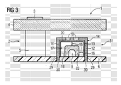
- FIG 3 shows a hob with a display element according to a third embodiment of the invention with an additional light distribution element.
- FIG 1 The basic structure of a hob 1 according to the invention is shown in FIG 1 in a highly simplified schematic representation.
- the cooktop 1 has operating elements 2 with an operating symbol imprint 3 on the surface of a glass-ceramic cooking plate 4 and a contactless switching device 5 arranged underneath the cooking plate 4 below the operating symbol imprint 3.
- the desired operation is detected by the switching device 5 and a corresponding action of the hob 1 is carried out.
- the switching device 5 is contacted on a arranged below the cooking plate 4 circuit board 6.
- an inventive display element 11 is arranged on the circuit board 6, an inventive display element 11 is arranged.
- This has a display symbol mask 12 and a light distribution element 13 arranged between luminous element 8 and display symbol mask 12.
- Display symbol mask 12 and light distribution element 13 form a cover element 14 spaced from the light-emitting element 8.
- a display symbol corresponding to the display symbol mask 10 is visible from above through the cooking plate 4. For example, at a triggered by touching the Particularungsymbolbedruckung 3 action of the hob 1, a corresponding control icon displayed.
- a luminous element 8 for the display element 11 is a light emitting diode (SMD LED) is used, which is mounted on a circuit board 6, namely plugged.
- the cap-shaped cover member 14 limits the distance 15 between the luminous element 8 and the display symbol mask 12 and between the luminous element 8 and the side walls 16.
- the closed side walls 16 of the light distribution element 13 extend to the circuit board 6.
- the cover element interior 18 is substantially light-tight.
- the side walls 16 and the rest of the Abdeckelementinnenraum 18 bounding surfaces have a white surface 17 and reflect the light of the luminous element 8 in the Abdeckelementinnenraum 18.
- the display symbol mask 12 serves as a carrier body of the cover 14 and has material openings 19, through which the of the luminous element 8 emitted light emerges from the display element 11 to the outside.
- the extending to the circuit board 6 wall portions of the display symbol mask 12 have at their support ends connecting pins 29 which eino in corresponding communication holes 30 in the circuit board 6 to form a press fit.
- the display symbol mask 12 is coated on its inner side 20 facing the luminous element 8 with light distribution element 13.
- the light distribution element 13 ensures a uniform distribution of light on the display symbol mask 12.
- the coating material used is a transparent, milky plastic. The coating is applied to the display symbol mask 12 by painting.
- FIG. 2 shows an embodiment of the invention with another display element 21 according to the invention.
- This display element 21 also has a display symbol mask 22 and a light distribution element 23 arranged between luminous element 8 and display symbol mask 22.
- Display symbol mask 22 and light distribution element 23 form a cover element 24 spaced from the light-emitting element 8.
- the support body of the cover element 24 is now formed by the light distribution element 23, while the display symbol mask 22 is applied on the outside 28 of the support body facing away from the light-emitting element 8 in the form of a lacquer.
- the paint is removed by a laser (not shown), so that the desired display symbol is present as a defect 25 in the paint.
- the closed side walls 26 of the light distribution element 23 in turn reach up to the printed circuit board 6 and, like the other surfaces surrounding the cover element interior 18, have a white surface 27, so that they emit the light of the luminous element 8 into the cover element interior 18 reflect.
- the extending to the circuit board 6 wall portions of the light distribution element 23 have at their support ends connecting pins 29 which eino in corresponding communication holes 30 in the circuit board 6 to form a press fit.
- FIG. 3 shows a further embodiment of the invention with a further display element 31 according to the invention.
- the display element 31 has a display symbol mask 12 and a light distribution element 13 arranged between lighting element 8 and display symbol mask 12.
- Display symbol mask 12 and light distribution element 13 form a cover element 14 spaced from the light-emitting element 8 in the manner of the display element 11 shown in FIG. 2.
- a second light distribution element 32 is mounted above the light-emitting element 8.
- the second light distribution element 32 since it no longer fulfills any further functions, for example as a carrier of an indicator symbol mask or the like, does not have to have a geometrically exact shape.
- the second light distribution element 32 can also be applied to the luminous element 8 as an irregular drop or dab, resulting in a very low production outlay.
- the distance 15 in the cover element interior 18 is reduced by the second light distribution element 32.
- the light distribution element 13 is smaller still spaced from the luminous element 8.
- the light distribution element 13 also has a small thickness compared to the embodiment shown in FIG.
Landscapes
- Engineering & Computer Science (AREA)
- Chemical & Material Sciences (AREA)
- Ceramic Engineering (AREA)
- Combustion & Propulsion (AREA)
- Mechanical Engineering (AREA)
- General Engineering & Computer Science (AREA)
- Physics & Mathematics (AREA)
- General Physics & Mathematics (AREA)
- Theoretical Computer Science (AREA)
- Illuminated Signs And Luminous Advertising (AREA)
Abstract
Description
- Die vorliegende Erfindung betrifft ein Haushaltsgerät, insbesondere Kochfeld, mit einem Anzeigeelement, welches ein Leuchtelement, eine Anzeigesymbolmaske und ein zwischen dem Leuchtelement und der Anzeigesymbolmaske angeordnetes Lichtverteilungselement aufweist. Darüber hinaus betrifft die Erfindung ein Anzeigeelement, die Verwendung eines Anzeigeelementes sowie ein Verfahren zur Herstellung eines Anzeigeelementes.
- Aus dem Stand der Technik sind Kochfelder mit Glaskeramik-Kochflächen bekannt, die ein unterhalb der Glaskeramik-Kochfläche angeordnetes Leuchtelement zur Anzeige von
- Bedien- oder Restwärme-Informationen oder dergleichen in Form von Zahlen, Buchstaben oder Symbolen aufweisen. Dabei wird beim Betrieb des Leuchtelementes durch die Glaskeramik-Kochfläche hindurch ein der Anzeigesymbolmaske entsprechendes Anzeigesymbol sichtbar. Ein solches Kochfeld ist u.a. aus der Patentschrift DE 198 02 571 C2 bekannt.
- Um eine besonders gleichmäßige Ausleuchtung der Anzeigesymbolmaske zu erreichen, ist es bekannt, zwischen dem Leuchtelement und der Anzeigesymbolmaske ein Lichtverteilungselement anzuordnen. Dabei wird das Leuchtelement von dem Lichtverteilungselement in Form einer quaderförmigen, milchigen Spritzgussmasse vollständig umschlossen. Auf dem so entstandenen Leuchtfeld wird dann die Anzeigesymbolmaske angeordnet. Die Spritzgußmasse ist dabei in einen weißen Rahmen eingespritzt, der als Begrenzung für das Lichtverteilungselement und zugleich als Reflektor dient.
- Eine Aufgabe der vorliegenden Erfindung ist es, die Herstellungskosten eines Haushaltsgerätes mit einem solchen Anzeigeelement zu verringern.
- Diese Aufgabe wird durch ein Haushaltsgerät nach Anspruch 1 beziehungsweise durch die in den weiteren unabhängigen Patentansprüchen angegebenen Erfindungsgegenstände gelöst.
- Es hat sich gezeigt, dass in einem Anzeigeelement eines Haushaltsgerätes für eine gleichmäßige Ausleuchtung der Anzeigesymbolmaske keinesfalls der vollständige Zwischenraum zwischen Leuchtelement und Anzeigesymbolmaske mit einem Lichtverteilungselement ausgefüllt sein muss. Vielmehr ist es ausreichend, wenn das Lichtverteilungselement unmittelbar benachbart zu der Anzeigesymbolmaske vorliegt. Erfindungsgemäß ist daher vorgesehen, dass Anzeigesymbolmaske und Lichtverteilungselement ein Abdeckelement bilden, das von dem Leuchtelement beabstandet angeordnet ist. Mit anderen Worten grenzt das Lichtverteilungselement nicht - wie im Stand der Technik üblich - direkt an das Leuchtelement an. Vielmehr besteht ein Zwischenraum zwischen diesen beiden Bauteilen, der nicht von dem Lichtverteilungselement ausgefüllt werden muss. Aufgrund dieses Zwischenraums ist eine Positionierung des Abdeckelements variabel und unabhängig von der Position des Leuchtelements möglich. Dadurch ist die Montage des Abdeckelements sehr einfach durchführbar.
- Neben einem einfacheren konstruktiven Aufbau führt die vorliegende Erfindung zu einer deutlichen Materialeinsparung bei dem Lichtverteilungselement, so dass eine Kostenreduzierung bei der Herstellung derartiger Anzeigeelemente erzielt wird. Zugleich werden somit auch die Gesamtherstellungskosten von Haushaltsgeräten verringert, in denen ein solches Anzeigeelement zum Einsatz kommt.
- Anzeigesymbolmaske und Lichtverteilungselement können auf verschiedene Art und Weise miteinander in Verbindung stehen, um das Abdeckelement zu bilden. So ist es beispielsweise möglich, dass das Lichtverteilungselement in Form einer Folie oder Platte oder dergleichen vorliegt und mit der Anzeigesymbolmaske verklebt, verschweisst, vernietet oder auf eine andere Art form- und/oder kraftschlüssig verbunden ist.
- Vorteilhafte Ausführungsformen der Erfindung sind in den Unteransprüchen angegeben.
- Gemäß einer bevorzugten Ausführungsform der Erfindung bildet die Anzeigesymbolmaske einen Trägerkörper des Abdeckelementes. Auf diesem Trägerkörper ist vorzugsweise das Lichtverteilungselement als eine Beschichtung aufgebracht.
- Als Trägerkörpermaterial können beliebige Materialien zum Einsatz kommen. Insbesondere Kunststoffe sind aufgrund ihrer guten Bearbeitbarkeit und ihres geringen Gewichtes gut geeignet. Dieser Trägerkörper ist an seiner dem Leuchtelement zugewandten Innenseite mit dem Lichtverteilungselement versehen. Das Lichtverteilungselement ist vorzugsweise ebenfalls aus einem Kunststoffmaterial gefertigt. Insbesondere kommen transparente, also lichtdurchscheinende Kunststoffe zum Einsatz, die aufgrund der diffusen Streuung des durchdringenden Lichtes sowohl ein milchiges Licht erzeugen, als auch für eine gleichmäßige Lichtverteilung sorgen. Das Aufbringen der Beschichtung erfolgt durch ein beliebiges geeignetes Beschichtungsverfahren, beispielsweise durch Aufdampfen, Zerstäuben, Streichen, Tauchen, Lackieren, Pulverbeschichten oder chemisches Abscheiden.
- In einer weiteren bevorzugten Ausführungsform der Erfindung ist der Trägerkörper des Abdeckelementes durch das Lichtverteilungselement gebildet. Auf diesem Trägerkörper ist die Anzeigesymbolmaske vorzugsweise in Form einer Beschichtung auf der dem Leuchtelement abgewandten Außenseite aufgebracht.
- Zur Bildung der Anzeigesymbolmaske wird dabei insbesondere ein lichtundurchlässiger, mittels Laser bearbeitbarer Lack zum Beschichten verwendet. Durch eine anschließende Laser-Bearbeitung des Lackes erfolgt bei der Herstellung des Anzeigeelementes ein Abtragen des gewünschten Anzeigesymbols im Lack. Das im Betrieb von dem Leuchtelement ausgehende Licht wird dann durch den transparenten Trägerkörper gleichmäßig verteilt und tritt als diffuses Licht durch die Anzeigesymbolmaske aus.
- Bei dieser Ausführungsform der Erfindung bleiben Trägerkörper und Beschichtung stets gleich. Lediglich die in den Lack durch Laser-Bearbeitung einzubringende Symbolform ändert sich. Daher ist nur eine einzige Anzeigeelement-Grundform erforderlich. Herstellungs- und Lagerhaltungsaufwand sind erheblich reduziert. Zudem lassen sich bei der Herstellung der Anzeigesymbolmaske in einer Lackschicht sämtliche Symbolformen darstellen. Eine Rücksichtnahme auf die beim Stand der Technik eventuell zu beachtende Halte- beziehungsweise Zwischenstege bei der Ausbildung einzelner Anzeigesymbole durch Ausstanzen oder dergleichen ist nicht notwendig. Schließlich kann die Herstellung derartiger Anzeigelemente innerhalb kürzester Zeit auf ein unterschiedliches Anzeigsymbol umgestellt werden. Hierzu ist lediglich eine geänderte Ansteuerung der Laser-Bearbeitungsanlage erforderlich. Bei geeigneter Ansteuerung können Anzeigeelemente mit verschiedensten Anzeigesymbolen in beliebiger Reihenfolge gefertigt werden.
- In einer weiteren Ausführungsform der Erfindung ist es vorgesehen, neben dem in dem Abdeckelement vorgesehenen Lichtverteilungselement ein zusätzliches Lichtverteilungselement zu verwenden. Dabei ist das zusätzliche Lichtverteilungselement vorzugsweise direkt auf dem Leuchtelement angeordnet. Das Leuchtelement ist - wie aus dem Stand der Technik bekannt - in dieses zusätzliche Lichtverteilungselement eingebettet. Durch geeignete Wahl des Materials des zusätzlichen Lichtverteilungselements kann in diesem Fall die Erzeugung eines diffusen Lichtes bereits durch das zusätzliche Lichtverteilungselement erfolgen, während das erste Lichtverteilungselement lediglich zur gleichmäßigen Verteilung des Lichts dient. Das erste Lichtverteilungselement kann dann beispielsweise als wesentlich dünnere Schicht ausgebildet sein und/oder aus einem anderen Material hergestellt werden.
- In einer weiteren Ausführungsform der Erfindung sind die Innenseiten des Abdeckelements zumindest teilweise, vorzugsweise jedoch vollständig mit dem Lichtverteilungselement bedeckt. Das Lichtverteilungselement wirkt somit in Verbindung mit der dahinterliegenden lichtundurchlässigen Anzeigesymbolmaske als eine Art Reflektor für das von dem Leuchtelement ausgesandte Licht. Zusätzliche Reflektoren, wie aus dem Stand der Technik bekannt, werden nicht benötigt, so dass die Anzahl der benötigten Bauteile verringert ist.
- In einer weiteren Ausführungsform der Erfindung weist das Abdeckelement einen im Wesentlichen geschlossenen Abdeckelementinnenraum auf. Vorzugsweise ist dabei das Abdeckelement selbst als geschlossenes Bauteil ausgebildet. Zudem ist die Befestigung des Abdeckelements auf einer Leiterplatte oder dergleichen vorzugsweise lichtdicht ausgeführt. Dadurch wird sichergestellt, dass an der Anzeigesymbolmaske eine besonders hoher Anteil des von dem Leuchtelement ausgesandten Lichtes zur Verfügung steht.
- In einer weiteren Ausführungsform der Erfindung ist das Abdeckelement mit seinem Trägerkörper auf einer Leiterplatte oder dergleichen befestigt. Hierzu ist der Trägerkörper zur Befestigung mit der Leiterplatte oder dergleichen ausgebildet. Vorzugsweise weist der Trägerkörper eine Anzahl von Steckerstiften zur Ausbildung einer Steckverbindung mit der Leiterplatte oder dergleichen auf. Dadurch ist eine einfache und zugleich zuverlässige Montage des Anzeigeelements möglich.
- Die Erfindung wird nachfolgend anhand von Ausführungsbeispielen beschrieben, die mit Hilfe der Figuren näher erläutert werden. Hierbei zeigt:
- FIG 1 ein Kochfeld mit einem Anzeigeelement gemäß einer ersten Ausführungsform der Erfindung mit einer Anzeigesymbolmaske als Trägerkörper,
- FIG 2 ein Kochfeld mit einem Anzeigeelement gemäß einer zweiten Ausführungsform der Erfindung mit einem Lichtverteilungselement als Trägerkörper,
- FIG 3 ein Kochfeld mit einem Anzeigeelement gemäß einer dritten Ausführungsform der Erfindung mit einem zusätzlichen Lichtverteilungselement.
- Den prinzipiellen Aufbau eines erfindungsgemäßen Kochfeldes 1 zeigt FIG 1 in einer stark vereinfachten schematischen Darstellung. Das Kochfeld 1 weist Bedienelemente 2 mit einer Bediensymbolbedruckung 3 auf der Oberfläche einer Glaskeramik-Kochplatte 4 und eine unterhalb der Bediensymbolbedruckung 3 unter der Kochplatte 4 angeordnete berührungslose Schalteinrichtung 5 auf. Durch Berühren der Kochplatte 4 im Bereich der Bediensymbolbedruckung 3 wird der Bedienwunsch durch die Schalteinrichtung 5 erfaßt und eine entsprechende Aktion des Kochfeldes 1 ausgeführt. Die Schalteinrichtung 5 ist auf einer unterhalb der Kochplatte 4 angeordneten Leiterplatte 6 kontaktiert.
- Auf der Leiterplatte 6 ist ein erfindungsgemäßes Anzeigeelements 11 angeordnet. Dieses weist eine Anzeigesymbolmaske 12 und ein zwischen Leuchtelement 8 und Anzeigesymbolmaske 12 angeordnetes Lichtverteilungselement 13 auf. Anzeigesymbolmaske 12 und Lichtverteilungselement 13 bilden ein von dem Leuchtelement 8 beabstandetes Abdeckelement 14. Beim Betrieb des Leuchtelementes 8 ist von oben durch die Kochplatte 4 hindurch ein der Anzeigesymbolmaske 10 entsprechendes Anzeigesymbol sichtbar. So wird beispielsweise bei einer durch Berühren der Bediensymbolbedruckung 3 ausgelösten Aktion des Kochfeldes 1 ein entsprechendes Bediensymbol angezeigt.
- Als Leuchtelement 8 für das Anzeigeelement 11 kommt eine Leuchtdiode (SMD-LED) zum Einsatz, die auf einer Leiterplatte 6 befestigt, nämlich aufgesteckt ist. Das kappenförmige Abdeckelement 14 begrenzt den Abstand 15 zwischen dem Leuchtelement 8 und der Anzeigesymbolmaske 12 als auch zwischen dem Leuchtelement 8 und den Seitenwänden 16. Die geschlossenen Seitenwände 16 des Lichtverteilungselements 13 reichen bis zu der Leiterplatte 6. Der Abdeckelementinnenraum 18 ist im Wesentlichen lichtdicht abgeschlossen. Die Seitenwände 16 und die übrigen den Abdeckelementinnenraum 18 begrenzenden Flächen weisen eine weiße Oberfläche 17 auf und reflektieren das Licht des Leuchtelementes 8 in den Abdeckelementinnenraum 18. Die Anzeigesymbolmaske 12 dient als Trägerkörper des Abdeckelements 14 und weist Materialdurchbrüche 19 auf, durch die das von dem Leuchtelement 8 ausgesandte Licht aus dem Anzeigeelement 11 nach außen austritt. Die bis zur Leiterplatte 6 verlaufenden Wandbereiche der Anzeigesymbolmaske 12 weisen an ihren Auflageenden Verbindungsstifte 29 auf, die in entsprechende Verbindungslöcher 30 in der Leiterplatte 6 unter Ausbildung einer Preßpassung einliegen.
- Die Anzeigesymbolmaske 12 ist an ihrer dem Leuchtelement 8 zugewandten Innenseite 20 mit Lichtverteilungselement 13 beschichtet. Das Lichtverteilungselement 13 gewährleistet eine gleichmäßige Lichtverteilung auf die Anzeigesymbolmaske 12. Als Beschichtungsmaterial dient ein transparenter, milchiger Kunststoff. Das Aufbringen der Beschichtung auf die Anzeigesymbolmaske 12 erfolgt durch Lackieren.
- FIG 2 zeigt eine Ausführungsform der Erfindung mit einem anderen erfindungsgemäßen Anzeigeelement 21. Auch dieses Anzeigeelement 21 weist eine Anzeigesymbolmaske 22 und ein zwischen Leuchtelement 8 und Anzeigesymbolmaske 22 angeordnetes Lichtverteilungselement 23 auf. Anzeigesymbolmaske 22 und Lichtverteilungselement 23 bilden ein von dem Leuchtelement 8 beabstandetes Abdeckelement 24. Jedoch wird nun der Trägerkörper des Abdeckelementes 24 durch das Lichtverteilungselement 23 gebildet, während die Anzeigesymbolmaske 22 auf der dem Leuchtelement 8 abgewandten Außenseite 28 des Trägerkörper in Form eines Lackes aufgebracht ist. Bei der Herstellung der Anzeigesymbolmaske 22 erfolgt ein Abtragen des Lackes durch einen Laser (nicht abgebildet), so dass das gewünschten Anzeigesymbol als Fehlstelle 25 im Lack vorliegt. Die geschlossenen Seitenwände 26 des Lichtverteilungselements 23 reichen wiederum bis zu der Leiterplatte 6 und weisen wie die übrigen den Abdeckelementinnenraum 18 begrenzenden Flächen eine weiße Oberfläche 27 auf, so dass sie das Licht des Leuchtelementes 8 in den Abdeckelementinnenraum 18 reflektieren. Die bis zur Leiterplatte 6 verlaufenden Wandbereiche des Lichtverteilungselements 23 weisen an ihren Auflageenden Verbindungsstifte 29 auf, die in entsprechende Verbindungslöcher 30 in der Leiterplatte 6 unter Ausbildung einer Preßpassung einliegen.
- FIG 3 stellt eine weitere Ausführungsform der Erfindung mit einem weiteren erfindungsgemäßen Anzeigeelement 31 dar. Auch hier weist das Anzeigeelement 31 eine Anzeigesymbolmaske 12 und ein zwischen Leuchtelement 8 und Anzeigesymbolmaske 12 angeordnetes Lichtverteilungselement 13 auf. Anzeigesymbolmaske 12 und Lichtverteilungselement 13 bilden ein von dem Leuchtelement 8 beabstandetes Abdeckelement 14 nach Art des in FIG 2 gezeigten Anzeigeelements 11. Zusätzlich zu dem in dem Abdeckelement 14 vorgesehenen Lichtverteilungselement 13 ist ein zweites Lichtverteilungselement 32 über dem Leuchtelement 8 angebracht. Das zweite Lichtverteilungselement 32 muss, da es keine weiteren Funktionen mehr erfüllt, beispielsweise als Träger einer Anzeigesymbolmaske oder dergleichen, keine geometrisch exakte Form aufweisen. Vielmehr kann das zweite Lichtverteilungselement 32 auch als unregelmäßiger Tropfen oder Kleks auf das Leuchtelement 8 aufgebracht werden, wodurch ein sehr geringer Herstellungsaufwand vorliegt. Durch das zweite Lichtverteilungselement 32 verringert sich der Abstand 15 im Abdeckelementinnenraum 18. Jedoch ist das Lichtverteilungselement 13 nach wie vor von dem Leuchtelement 8 beabstandet. Das Lichtverteilungselement 13 weist zudem im Vergleich zu der in FIG 2 gezeigten Ausführungsform eine geringer Dicke auf.
Claims (15)
- Haushaltsgerät, insbesondere Kochfeld, mit wenigstens einem Anzeigeelement (11; 21; 31), welches ein Leuchtelement (8), eine Anzeigesymbolmaske (12; 22) und ein zwischen dem Leuchtelement (8) und der Anzeigesymbolmaske (12; 22) angeordnetes Lichtverteilungselement (13; 23) aufweist, dadurch gekennzeichnet, dass die Anzeigesymbolmaske (12; 22) und das Lichtverteilungselement (13; 23) ein von dem Leuchtelement (8) beabstandetes Abdeckelement (14; 24) bilden.
- Haushaltsgerät nach Anspruch 1, dadurch gekennzeichnet, dass die Anzeigesymbolmaske (12) ein Trägerkörper des Abdeckelementes (14) ist.
- Haushaltsgerät nach Anspruch 2, dadurch gekennzeichnet, dass das Lichtverteilungselement (13) eine Beschichtung des Trägerkörpers ist.
- Haushaltsgerät nach Anspruch 1, dadurch gekennzeichnet, dass das Lichtverteilungselement (23) ein Trägerkörper des Abdeckelementes (24) ist.
- Haushaltsgerät nach Anspruch 4, dadurch gekennzeichnet, dass die Anzeigesymbolmaske (22) eine Beschichtung des Trägerkörpers ist.
- Haushaltsgerät nach einem der Ansprüche 1 bis 5, dadurch gekennzeichnet, dass die Innenseiten des Abdeckelements (14; 24) zumindest teilweise mit dem Lichtverteilungselement (13; 23) bedeckt sind.
- Haushaltsgerät nach einem der Ansprüche 1 bis 6, dadurch gekennzeichnet, dass die Innenseiten des Abdeckelements (14; 24) vollständig mit dem Lichtverteilungselement (13; 23) bedeckt sind.
- Haushaltsgerät nach einem der Ansprüche 1 bis 7, dadurch gekennzeichnet, dass das Abdeckelement (14; 24) einen im Wesentlichen geschlossenen Abdeckelementinnenraum (18) aufweist.
- Haushaltsgerät nach einem der Ansprüche 1 bis 8, dadurch gekennzeichnet, dass das Abdeckelement (14; 24) mit seinem Trägerkörper auf einer Leiterplatte (6) oder dergleichen befestigt ist.
- Anzeigeelement für ein Haushaltsgerät, mit einem Leuchtelement (8), einer Anzeigesymbolmaske (12; 22) und einem zwischen dem Leuchtelement (8) und der Anzeigesymbolmaske (12; 22) angeordneten Lichtverteilungselement (13; 23), dadurch gekennzeichnet, dass die Anzeigesymbolmaske (12; 22) und das Lichtverteilungselement (13; 23) ein von dem Leuchtelement (8) beabstandetes Abdeckelement (14; 24) bilden.
- Verwendung eines Anzeigeelementes (11; 21; 31) nach Anspruch 10 für ein Haushaltsgerät, insbesondere für ein Kochfeld (1).
- Verfahren zur Herstellung eines ein Leuchtelement (8) aufweisenden Anzeigeelementes (11; 21; 31) für ein Haushaltsgerät (1), dadurch gekennzeichnet, dass eine Anzeigesymbolmaske (12; 22) und ein zwischen dem Leuchtelement (8) und der Anzeigesymbolmaske (12; 22) angeordnetes Lichtverteilungselement (13; 23) zu einem von dem Leuchtelement (8) beabstandeten Abdeckelement (14; 24) ausgebildet werden.
- Verfahren nach Anspruch 12, dadurch gekennzeichnet, dass das Lichtverteilungselement (13) als Beschichtung auf die Anzeigesymbolmaske (12) aufgebracht wird.
- Verfahren nach Anspruch 12, dadurch gekennzeichnet, dass die Anzeigesymbolmaske (22) als Beschichtung auf das Lichtverteilungselement (23) aufgebracht wird.
-
Priority Applications (2)
| Application Number | Priority Date | Filing Date | Title |
|---|---|---|---|
| SI200532222T SI1672283T1 (sl) | 2004-12-20 | 2005-10-28 | Prikazovalni element za gospodinjski aparat |
| PL05110111T PL1672283T3 (pl) | 2004-12-20 | 2005-10-28 | Element wyświetlacza do urządzenia gospodarstwa domowego |
Applications Claiming Priority (1)
| Application Number | Priority Date | Filing Date | Title |
|---|---|---|---|
| DE200410061305 DE102004061305A1 (de) | 2004-12-20 | 2004-12-20 | Haushaltsgerät mit einem Anzeigeelement |
Publications (2)
| Publication Number | Publication Date |
|---|---|
| EP1672283A1 true EP1672283A1 (de) | 2006-06-21 |
| EP1672283B1 EP1672283B1 (de) | 2018-08-15 |
Family
ID=36084224
Family Applications (1)
| Application Number | Title | Priority Date | Filing Date |
|---|---|---|---|
| EP05110111.1A Expired - Lifetime EP1672283B1 (de) | 2004-12-20 | 2005-10-28 | Anzeigeelement für eine Haushaltsgerät |
Country Status (5)
| Country | Link |
|---|---|
| EP (1) | EP1672283B1 (de) |
| DE (1) | DE102004061305A1 (de) |
| ES (1) | ES2684694T3 (de) |
| PL (1) | PL1672283T3 (de) |
| SI (1) | SI1672283T1 (de) |
Cited By (2)
| Publication number | Priority date | Publication date | Assignee | Title |
|---|---|---|---|---|
| WO2011012501A1 (de) * | 2009-07-28 | 2011-02-03 | E.G.O. Elektro-Gerätebau GmbH | Sensorelementeinrichtung und verfahren zur herstellung eines formkörpers einer sensorelementeinrichtung |
| CN114584128A (zh) * | 2020-12-02 | 2022-06-03 | Bsh家用电器有限公司 | 用于家用电器的操作单元 |
Families Citing this family (1)
| Publication number | Priority date | Publication date | Assignee | Title |
|---|---|---|---|---|
| DE102008042348A1 (de) | 2008-09-25 | 2010-04-01 | BSH Bosch und Siemens Hausgeräte GmbH | Abdeckelement für eine Lichtquelle einer Anzeigeeinrichtung und Anzeigeeinrichtung |
Citations (10)
| Publication number | Priority date | Publication date | Assignee | Title |
|---|---|---|---|---|
| DE1679226A1 (de) * | 1967-11-29 | 1971-03-25 | Neff Werke | Anzeigevorrichtung fuer den Betriebszustand an Kochherden |
| DE3621436A1 (de) * | 1986-06-26 | 1988-01-14 | Bosch Siemens Hausgeraete | Bedien- und anzeigevorrichtung fuer hausgeraete |
| JPH0497274A (ja) * | 1990-08-10 | 1992-03-30 | Fujitsu General Ltd | 表示ユニット |
| JPH0533947A (ja) * | 1991-07-24 | 1993-02-09 | Matsushita Electric Ind Co Ltd | 電気加熱調理器 |
| US5809680A (en) * | 1994-07-14 | 1998-09-22 | Schott Glaswerke | Arrangement for displaying information and operating states on a cooking apparatus |
| US6376809B1 (en) * | 1998-01-23 | 2002-04-23 | Bsh Bosch Und Siemens Hausgeraete Gmbh | Cooktop with display elements |
| US20030230017A1 (en) * | 2000-12-21 | 2003-12-18 | Johannes Geyer | Electrically operated household appliance |
| DE10236718A1 (de) * | 2002-08-06 | 2004-02-12 | E.G.O. Control Systems Gmbh & Co. Kg | Elektrohaushaltsgerät mit Anzeigeeinrichtung |
| DE10309225A1 (de) * | 2003-03-03 | 2004-09-16 | BSH Bosch und Siemens Hausgeräte GmbH | Haushaltsgerät |
| EP1462726A2 (de) * | 2003-03-24 | 2004-09-29 | BSH Bosch und Siemens Hausgeräte GmbH | Geräteblende mit beleuchtbarer Anzeigevorrichtung |
Family Cites Families (3)
| Publication number | Priority date | Publication date | Assignee | Title |
|---|---|---|---|---|
| DE19720730A1 (de) * | 1997-05-16 | 1998-11-19 | Siedle & Soehne S | Anzeigevorrichtung |
| DE10123633A1 (de) * | 2001-05-09 | 2003-02-06 | Ego Elektro Geraetebau Gmbh | Sensorelement |
| DE10250675A1 (de) * | 2002-10-31 | 2004-05-19 | Hella Kg Hueck & Co. | Anzeigeneinheit, isbesondere für Kraftfahrzeuge |
-
2004
- 2004-12-20 DE DE200410061305 patent/DE102004061305A1/de not_active Withdrawn
-
2005
- 2005-10-28 ES ES05110111.1T patent/ES2684694T3/es not_active Expired - Lifetime
- 2005-10-28 SI SI200532222T patent/SI1672283T1/sl unknown
- 2005-10-28 PL PL05110111T patent/PL1672283T3/pl unknown
- 2005-10-28 EP EP05110111.1A patent/EP1672283B1/de not_active Expired - Lifetime
Patent Citations (10)
| Publication number | Priority date | Publication date | Assignee | Title |
|---|---|---|---|---|
| DE1679226A1 (de) * | 1967-11-29 | 1971-03-25 | Neff Werke | Anzeigevorrichtung fuer den Betriebszustand an Kochherden |
| DE3621436A1 (de) * | 1986-06-26 | 1988-01-14 | Bosch Siemens Hausgeraete | Bedien- und anzeigevorrichtung fuer hausgeraete |
| JPH0497274A (ja) * | 1990-08-10 | 1992-03-30 | Fujitsu General Ltd | 表示ユニット |
| JPH0533947A (ja) * | 1991-07-24 | 1993-02-09 | Matsushita Electric Ind Co Ltd | 電気加熱調理器 |
| US5809680A (en) * | 1994-07-14 | 1998-09-22 | Schott Glaswerke | Arrangement for displaying information and operating states on a cooking apparatus |
| US6376809B1 (en) * | 1998-01-23 | 2002-04-23 | Bsh Bosch Und Siemens Hausgeraete Gmbh | Cooktop with display elements |
| US20030230017A1 (en) * | 2000-12-21 | 2003-12-18 | Johannes Geyer | Electrically operated household appliance |
| DE10236718A1 (de) * | 2002-08-06 | 2004-02-12 | E.G.O. Control Systems Gmbh & Co. Kg | Elektrohaushaltsgerät mit Anzeigeeinrichtung |
| DE10309225A1 (de) * | 2003-03-03 | 2004-09-16 | BSH Bosch und Siemens Hausgeräte GmbH | Haushaltsgerät |
| EP1462726A2 (de) * | 2003-03-24 | 2004-09-29 | BSH Bosch und Siemens Hausgeräte GmbH | Geräteblende mit beleuchtbarer Anzeigevorrichtung |
Non-Patent Citations (2)
| Title |
|---|
| PATENT ABSTRACTS OF JAPAN vol. 016, no. 330 (P - 1388) 17 July 1992 (1992-07-17) * |
| PATENT ABSTRACTS OF JAPAN vol. 017, no. 322 (M - 1432) 18 June 1993 (1993-06-18) * |
Cited By (5)
| Publication number | Priority date | Publication date | Assignee | Title |
|---|---|---|---|---|
| WO2011012501A1 (de) * | 2009-07-28 | 2011-02-03 | E.G.O. Elektro-Gerätebau GmbH | Sensorelementeinrichtung und verfahren zur herstellung eines formkörpers einer sensorelementeinrichtung |
| CN102577127A (zh) * | 2009-07-28 | 2012-07-11 | E.G.O.电气设备制造股份有限公司 | 传感器元件设备及生产传感器元件设备的模制主体的方法 |
| US9287866B2 (en) | 2009-07-28 | 2016-03-15 | E.G.O. Elektro-Gerätebau GmbH | Sensor element device and method for producing a molded body of a sensor element device |
| CN102577127B (zh) * | 2009-07-28 | 2016-05-11 | E.G.O.电气设备制造股份有限公司 | 传感器元件设备及生产传感器元件设备的模制主体的方法 |
| CN114584128A (zh) * | 2020-12-02 | 2022-06-03 | Bsh家用电器有限公司 | 用于家用电器的操作单元 |
Also Published As
| Publication number | Publication date |
|---|---|
| DE102004061305A1 (de) | 2006-06-22 |
| ES2684694T3 (es) | 2018-10-04 |
| SI1672283T1 (sl) | 2018-10-30 |
| EP1672283B1 (de) | 2018-08-15 |
| PL1672283T3 (pl) | 2019-02-28 |
Similar Documents
| Publication | Publication Date | Title |
|---|---|---|
| EP1573111B1 (de) | Elektrohaushaltsgerät mit bedieneinrichtung und anzeigeeinrichtung | |
| EP1257057B1 (de) | Sensorelement für einen kapazitiven Berührungsschalter | |
| EP2460273B1 (de) | Sensorelementeinrichtung und verfahren zur herstellung eines formkörpers einer sensorelementeinrichtung | |
| DE202012104088U1 (de) | Formteil | |
| DE102004029248B4 (de) | Beleuchtungssystem für Anzeigen, insbesondere in Fahrzeugen sowie Abdeckungsbauteil für derartiges Beleuchtungssystem | |
| DE102009036162A1 (de) | Sensorelementeinrichtung | |
| DE102010013947B4 (de) | Kapazitiver Annäherungssensor | |
| DE102018207071B4 (de) | Bedien- und/oder Anzeigeelement für ein Kraftfahrzeug | |
| DE102012223779A1 (de) | Haushaltsgerät mit kapazitivem Bedienpanel und Verfahren zu seiner Herstellung | |
| DE102013021879A1 (de) | Berührungs- und/oder annäherungsempfindliche Eingabevorrichtung | |
| DE102012101314B4 (de) | Formteil und Verfahren zur Herstellung eines Formteils | |
| DE102016212995A1 (de) | Bedienmodul für ein Haushaltsgerät | |
| EP3490339A1 (de) | Topferkennungssensor für ein induktionskochfeld und induktionskochfeld | |
| DE202019005317U1 (de) | Beleuchtbares Zierteil | |
| EP3385623B1 (de) | Herd mit einer bedien- und anzeigeeinheit | |
| EP3232428B1 (de) | Anzeigeelement, anzeigevorrichtung mit einem solchen anzeigeelement und elektrogerät mit einer solchen anzeigevorrichtung | |
| DE102010062428B4 (de) | Optische Bedien- und/oder Anzeigeeinheit | |
| DE102013214164A1 (de) | Bedienteil für eine Bedieneinrichtung und Bedieneinrichtung | |
| EP1678448B1 (de) | Blende für ein gerätegehäuse und verfahren zu dessen herstellung | |
| EP1672283B1 (de) | Anzeigeelement für eine Haushaltsgerät | |
| DE102023103205A1 (de) | Formteil | |
| DE202013011515U1 (de) | Berührungs- und/oder annäherungsempfindliche Eingabevorrichtung | |
| DE102016002893A1 (de) | Ein- und/oder Ausgabegerät mit hinterleuchteten Symbolen | |
| EP2375396B1 (de) | Beleuchtungseinheit, deren Verwendung sowie Verfahren zur Herstellung der Beleuchtungseinheit | |
| DE102020122189A1 (de) | Zierteil mit einstückiger aus Festsilikonen gebildeter Multifunktionsschicht |
Legal Events
| Date | Code | Title | Description |
|---|---|---|---|
| PUAI | Public reference made under article 153(3) epc to a published international application that has entered the european phase |
Free format text: ORIGINAL CODE: 0009012 |
|
| AK | Designated contracting states |
Kind code of ref document: A1 Designated state(s): AT BE BG CH CY CZ DE DK EE ES FI FR GB GR HU IE IS IT LI LT LU LV MC NL PL PT RO SE SI SK TR |
|
| AX | Request for extension of the european patent |
Extension state: AL BA HR MK YU |
|
| 17P | Request for examination filed |
Effective date: 20061221 |
|
| 17Q | First examination report despatched |
Effective date: 20070125 |
|
| AKX | Designation fees paid |
Designated state(s): AT BE BG CH CY CZ DE DK EE ES FI FR GB GR HU IE IS IT LI LT LU LV MC NL PL PT RO SE SI SK TR |
|
| RAP1 | Party data changed (applicant data changed or rights of an application transferred) |
Owner name: BSH HAUSGERAETE GMBH |
|
| GRAP | Despatch of communication of intention to grant a patent |
Free format text: ORIGINAL CODE: EPIDOSNIGR1 |
|
| INTG | Intention to grant announced |
Effective date: 20180327 |
|
| GRAS | Grant fee paid |
Free format text: ORIGINAL CODE: EPIDOSNIGR3 |
|
| GRAA | (expected) grant |
Free format text: ORIGINAL CODE: 0009210 |
|
| AK | Designated contracting states |
Kind code of ref document: B1 Designated state(s): AT BE BG CH CY CZ DE DK EE ES FI FR GB GR HU IE IS IT LI LT LU LV MC NL PL PT RO SE SI SK TR |
|
| REG | Reference to a national code |
Ref country code: CH Ref legal event code: EP Ref country code: GB Ref legal event code: FG4D Free format text: NOT ENGLISH Ref country code: AT Ref legal event code: REF Ref document number: 1030229 Country of ref document: AT Kind code of ref document: T Effective date: 20180815 |
|
| REG | Reference to a national code |
Ref country code: IE Ref legal event code: FG4D Free format text: LANGUAGE OF EP DOCUMENT: GERMAN |
|
| REG | Reference to a national code |
Ref country code: DE Ref legal event code: R096 Ref document number: 502005015880 Country of ref document: DE |
|
| REG | Reference to a national code |
Ref country code: ES Ref legal event code: FG2A Ref document number: 2684694 Country of ref document: ES Kind code of ref document: T3 Effective date: 20181004 |
|
| REG | Reference to a national code |
Ref country code: FR Ref legal event code: PLFP Year of fee payment: 14 |
|
| REG | Reference to a national code |
Ref country code: NL Ref legal event code: MP Effective date: 20180815 |
|
| REG | Reference to a national code |
Ref country code: LT Ref legal event code: MG4D |
|
| PG25 | Lapsed in a contracting state [announced via postgrant information from national office to epo] |
Ref country code: FI Free format text: LAPSE BECAUSE OF FAILURE TO SUBMIT A TRANSLATION OF THE DESCRIPTION OR TO PAY THE FEE WITHIN THE PRESCRIBED TIME-LIMIT Effective date: 20180815 Ref country code: IS Free format text: LAPSE BECAUSE OF FAILURE TO SUBMIT A TRANSLATION OF THE DESCRIPTION OR TO PAY THE FEE WITHIN THE PRESCRIBED TIME-LIMIT Effective date: 20181215 Ref country code: SE Free format text: LAPSE BECAUSE OF FAILURE TO SUBMIT A TRANSLATION OF THE DESCRIPTION OR TO PAY THE FEE WITHIN THE PRESCRIBED TIME-LIMIT Effective date: 20180815 Ref country code: BG Free format text: LAPSE BECAUSE OF FAILURE TO SUBMIT A TRANSLATION OF THE DESCRIPTION OR TO PAY THE FEE WITHIN THE PRESCRIBED TIME-LIMIT Effective date: 20181115 Ref country code: GR Free format text: LAPSE BECAUSE OF FAILURE TO SUBMIT A TRANSLATION OF THE DESCRIPTION OR TO PAY THE FEE WITHIN THE PRESCRIBED TIME-LIMIT Effective date: 20181116 Ref country code: LT Free format text: LAPSE BECAUSE OF FAILURE TO SUBMIT A TRANSLATION OF THE DESCRIPTION OR TO PAY THE FEE WITHIN THE PRESCRIBED TIME-LIMIT Effective date: 20180815 Ref country code: NL Free format text: LAPSE BECAUSE OF FAILURE TO SUBMIT A TRANSLATION OF THE DESCRIPTION OR TO PAY THE FEE WITHIN THE PRESCRIBED TIME-LIMIT Effective date: 20180815 |
|
| PG25 | Lapsed in a contracting state [announced via postgrant information from national office to epo] |
Ref country code: LV Free format text: LAPSE BECAUSE OF FAILURE TO SUBMIT A TRANSLATION OF THE DESCRIPTION OR TO PAY THE FEE WITHIN THE PRESCRIBED TIME-LIMIT Effective date: 20180815 |
|
| PG25 | Lapsed in a contracting state [announced via postgrant information from national office to epo] |
Ref country code: CZ Free format text: LAPSE BECAUSE OF FAILURE TO SUBMIT A TRANSLATION OF THE DESCRIPTION OR TO PAY THE FEE WITHIN THE PRESCRIBED TIME-LIMIT Effective date: 20180815 Ref country code: RO Free format text: LAPSE BECAUSE OF FAILURE TO SUBMIT A TRANSLATION OF THE DESCRIPTION OR TO PAY THE FEE WITHIN THE PRESCRIBED TIME-LIMIT Effective date: 20180815 Ref country code: IT Free format text: LAPSE BECAUSE OF FAILURE TO SUBMIT A TRANSLATION OF THE DESCRIPTION OR TO PAY THE FEE WITHIN THE PRESCRIBED TIME-LIMIT Effective date: 20180815 Ref country code: EE Free format text: LAPSE BECAUSE OF FAILURE TO SUBMIT A TRANSLATION OF THE DESCRIPTION OR TO PAY THE FEE WITHIN THE PRESCRIBED TIME-LIMIT Effective date: 20180815 |
|
| REG | Reference to a national code |
Ref country code: DE Ref legal event code: R097 Ref document number: 502005015880 Country of ref document: DE |
|
| PG25 | Lapsed in a contracting state [announced via postgrant information from national office to epo] |
Ref country code: DK Free format text: LAPSE BECAUSE OF FAILURE TO SUBMIT A TRANSLATION OF THE DESCRIPTION OR TO PAY THE FEE WITHIN THE PRESCRIBED TIME-LIMIT Effective date: 20180815 Ref country code: SK Free format text: LAPSE BECAUSE OF FAILURE TO SUBMIT A TRANSLATION OF THE DESCRIPTION OR TO PAY THE FEE WITHIN THE PRESCRIBED TIME-LIMIT Effective date: 20180815 |
|
| REG | Reference to a national code |
Ref country code: CH Ref legal event code: PL |
|
| PLBE | No opposition filed within time limit |
Free format text: ORIGINAL CODE: 0009261 |
|
| STAA | Information on the status of an ep patent application or granted ep patent |
Free format text: STATUS: NO OPPOSITION FILED WITHIN TIME LIMIT |
|
| REG | Reference to a national code |
Ref country code: BE Ref legal event code: MM Effective date: 20181031 |
|
| PG25 | Lapsed in a contracting state [announced via postgrant information from national office to epo] |
Ref country code: LU Free format text: LAPSE BECAUSE OF NON-PAYMENT OF DUE FEES Effective date: 20181028 Ref country code: MC Free format text: LAPSE BECAUSE OF FAILURE TO SUBMIT A TRANSLATION OF THE DESCRIPTION OR TO PAY THE FEE WITHIN THE PRESCRIBED TIME-LIMIT Effective date: 20180815 |
|
| 26N | No opposition filed |
Effective date: 20190516 |
|
| GBPC | Gb: european patent ceased through non-payment of renewal fee |
Effective date: 20181115 |
|
| REG | Reference to a national code |
Ref country code: IE Ref legal event code: MM4A |
|
| PG25 | Lapsed in a contracting state [announced via postgrant information from national office to epo] |
Ref country code: CH Free format text: LAPSE BECAUSE OF NON-PAYMENT OF DUE FEES Effective date: 20181031 Ref country code: LI Free format text: LAPSE BECAUSE OF NON-PAYMENT OF DUE FEES Effective date: 20181031 Ref country code: BE Free format text: LAPSE BECAUSE OF NON-PAYMENT OF DUE FEES Effective date: 20181031 |
|
| PG25 | Lapsed in a contracting state [announced via postgrant information from national office to epo] |
Ref country code: IE Free format text: LAPSE BECAUSE OF NON-PAYMENT OF DUE FEES Effective date: 20181028 |
|
| REG | Reference to a national code |
Ref country code: AT Ref legal event code: MM01 Ref document number: 1030229 Country of ref document: AT Kind code of ref document: T Effective date: 20181028 |
|
| PG25 | Lapsed in a contracting state [announced via postgrant information from national office to epo] |
Ref country code: GB Free format text: LAPSE BECAUSE OF NON-PAYMENT OF DUE FEES Effective date: 20181115 |
|
| PG25 | Lapsed in a contracting state [announced via postgrant information from national office to epo] |
Ref country code: AT Free format text: LAPSE BECAUSE OF NON-PAYMENT OF DUE FEES Effective date: 20181028 |
|
| PGFP | Annual fee paid to national office [announced via postgrant information from national office to epo] |
Ref country code: ES Payment date: 20191120 Year of fee payment: 15 Ref country code: PL Payment date: 20191018 Year of fee payment: 15 Ref country code: SI Payment date: 20191016 Year of fee payment: 15 |
|
| PG25 | Lapsed in a contracting state [announced via postgrant information from national office to epo] |
Ref country code: PT Free format text: LAPSE BECAUSE OF FAILURE TO SUBMIT A TRANSLATION OF THE DESCRIPTION OR TO PAY THE FEE WITHIN THE PRESCRIBED TIME-LIMIT Effective date: 20180815 |
|
| PG25 | Lapsed in a contracting state [announced via postgrant information from national office to epo] |
Ref country code: CY Free format text: LAPSE BECAUSE OF FAILURE TO SUBMIT A TRANSLATION OF THE DESCRIPTION OR TO PAY THE FEE WITHIN THE PRESCRIBED TIME-LIMIT Effective date: 20180815 Ref country code: HU Free format text: LAPSE BECAUSE OF FAILURE TO SUBMIT A TRANSLATION OF THE DESCRIPTION OR TO PAY THE FEE WITHIN THE PRESCRIBED TIME-LIMIT; INVALID AB INITIO Effective date: 20051028 |
|
| PG25 | Lapsed in a contracting state [announced via postgrant information from national office to epo] |
Ref country code: SI Free format text: LAPSE BECAUSE OF NON-PAYMENT OF DUE FEES Effective date: 20201029 |
|
| REG | Reference to a national code |
Ref country code: SI Ref legal event code: KO00 Effective date: 20210825 |
|
| REG | Reference to a national code |
Ref country code: ES Ref legal event code: FD2A Effective date: 20220128 |
|
| PG25 | Lapsed in a contracting state [announced via postgrant information from national office to epo] |
Ref country code: ES Free format text: LAPSE BECAUSE OF NON-PAYMENT OF DUE FEES Effective date: 20201029 |
|
| PG25 | Lapsed in a contracting state [announced via postgrant information from national office to epo] |
Ref country code: PL Free format text: LAPSE BECAUSE OF NON-PAYMENT OF DUE FEES Effective date: 20201028 |
|
| PGFP | Annual fee paid to national office [announced via postgrant information from national office to epo] |
Ref country code: FR Payment date: 20221020 Year of fee payment: 18 |
|
| PGFP | Annual fee paid to national office [announced via postgrant information from national office to epo] |
Ref country code: TR Payment date: 20221021 Year of fee payment: 18 Ref country code: DE Payment date: 20221031 Year of fee payment: 18 |
|
| REG | Reference to a national code |
Ref country code: DE Ref legal event code: R119 Ref document number: 502005015880 Country of ref document: DE |
|
| PG25 | Lapsed in a contracting state [announced via postgrant information from national office to epo] |
Ref country code: FR Free format text: LAPSE BECAUSE OF NON-PAYMENT OF DUE FEES Effective date: 20231031 Ref country code: DE Free format text: LAPSE BECAUSE OF NON-PAYMENT OF DUE FEES Effective date: 20240501 |