EP1672130A1 - Flush device for a lavatory flush tank - Google Patents
Flush device for a lavatory flush tank Download PDFInfo
- Publication number
- EP1672130A1 EP1672130A1 EP04405772A EP04405772A EP1672130A1 EP 1672130 A1 EP1672130 A1 EP 1672130A1 EP 04405772 A EP04405772 A EP 04405772A EP 04405772 A EP04405772 A EP 04405772A EP 1672130 A1 EP1672130 A1 EP 1672130A1
- Authority
- EP
- European Patent Office
- Prior art keywords
- closure body
- float
- drain valve
- adjusting element
- flush
- Prior art date
- Legal status (The legal status is an assumption and is not a legal conclusion. Google has not performed a legal analysis and makes no representation as to the accuracy of the status listed.)
- Granted
Links
- 238000011010 flushing procedure Methods 0.000 claims abstract description 10
- 230000008719 thickening Effects 0.000 claims description 3
- 230000001105 regulatory effect Effects 0.000 abstract 3
- XLYOFNOQVPJJNP-UHFFFAOYSA-N water Substances O XLYOFNOQVPJJNP-UHFFFAOYSA-N 0.000 description 17
- 230000008878 coupling Effects 0.000 description 2
- 238000010168 coupling process Methods 0.000 description 2
- 238000005859 coupling reaction Methods 0.000 description 2
- 230000009977 dual effect Effects 0.000 description 2
- 238000010276 construction Methods 0.000 description 1
- 230000001419 dependent effect Effects 0.000 description 1
- 238000004519 manufacturing process Methods 0.000 description 1
Images
Classifications
-
- E—FIXED CONSTRUCTIONS
- E03—WATER SUPPLY; SEWERAGE
- E03D—WATER-CLOSETS OR URINALS WITH FLUSHING DEVICES; FLUSHING VALVES THEREFOR
- E03D1/00—Water flushing devices with cisterns ; Setting up a range of flushing devices or water-closets; Combinations of several flushing devices
- E03D1/02—High-level flushing systems
- E03D1/14—Cisterns discharging variable quantities of water also cisterns with bell siphons in combination with flushing valves
- E03D1/142—Cisterns discharging variable quantities of water also cisterns with bell siphons in combination with flushing valves in cisterns with flushing valves
- E03D1/144—Cisterns discharging variable quantities of water also cisterns with bell siphons in combination with flushing valves in cisterns with flushing valves having a single flush outlet and an additional float for delaying the valve closure
-
- E—FIXED CONSTRUCTIONS
- E03—WATER SUPPLY; SEWERAGE
- E03D—WATER-CLOSETS OR URINALS WITH FLUSHING DEVICES; FLUSHING VALVES THEREFOR
- E03D1/00—Water flushing devices with cisterns ; Setting up a range of flushing devices or water-closets; Combinations of several flushing devices
- E03D1/30—Valves for high or low level cisterns; Their arrangement ; Flushing mechanisms in the cistern, optionally with provisions for a pre-or a post- flushing and for cutting off the flushing mechanism in case of leakage
- E03D1/34—Flushing valves for outlets; Arrangement of outlet valves
- E03D1/35—Flushing valves having buoyancy
Definitions
- the invention relates to a drain valve for a cistern with a valve housing having an outlet opening with a valve seat, with a closure body which cooperates at a lower end with the valve seat, with a Zweimengenbet2011 Trentonsvorraum, with which the closure body can be raised with different stroke, with a upper switchable float for a partial flush and a lower switchable float for a full flush, the upper float is height-adjustable mounted on an adjustment.
- Drain valves of this type allow a two-stage flush. This allows a partial flush with an amount of water that is much smaller than the amount of water in the cistern. This makes it possible to significantly reduce the water consumption in cisterns.
- a drain valve of this type has become known for example from WO 02/059431.
- it is disadvantageous that it consists of comparatively many moving parts and therefore is correspondingly expensive to manufacture and prone to failure.
- the invention has for its object to provide a drain valve of the type mentioned, which is less expensive and cheaper to produce.
- the drain valve should still be reliable.
- the object is achieved according to claim 1, characterized in that the adjusting element is coupled directly to the closure body, that after triggering a partial flushing of the closure body rests on the adjustment and that when triggering a full flush the closure body rests on the activated lower float and the adjustment is decoupled from the closure body.
- the adjusting element has a lower stop, with which in a partial flushing of the closure body is coupled to the upper float.
- a stop can be realized very easily and inexpensively, for example, by a thickening of the lower end of the adjustment.
- the lower float has means for a stroke limitation.
- a stroke limitation can be realized in a particularly simple manner, in particular by a nose on the lower float, which cooperates with a shoulder on a backdrop of the closure tube.
- a bearing part of the closure body can slide up on the adjusting element without the upper float becoming effective. According to a development of the invention, this is realized by a tolerance range at the lower end of the adjustment.
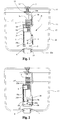
- the drain valve 1 shows a cistern 13, in which a drain valve 1 is mounted.
- the drain valve 1 has a housing 2 having at a lower end a nozzle 21 which is fixed in a known manner to the bottom 22 a of a box body 22 and which forms an outlet opening 3 with a valve seat 4.
- the valve seat 4 cooperates with a closure body 5, which is designed as a valve tube and which can be raised with a pull rod 14 for triggering a flushing.
- the pull rod 14 is arranged on a dual-quantity actuation device 7 and acts as shown on the closure body 5.
- the ZweimengenbetHence Cosmeticsvorraum 7 has, for example, buttons 12 and pushers 15. Such a suitable operation has become known, for example, from WO 01/46528 of the applicant.
- the box body 22 is filled with rinse water 17.
- the water surface 18 is in this case below an overflow opening 5a of the closure body 15.
- the closure body 5 has in the region of a lower end 6 an integrally formed web 19 which, as can be seen, protrudes radially and forms a bearing part or coupling part for an adjusting element 10.
- the web 19 has a passage 19a into which the adjusting element 10 protrudes with a tolerance range 10d.
- a stop 10b is arranged, here as a thickening is trained.
- the adjusting element 10 has a thread 10c into which an upper float 8 is screwed. By turning the adjusting element 10, the upper float 8 can be adjusted continuously in height.
- the adjusting member 10 also has an upper end 10a, which projects into a guide member 16 slidably.
- the adjusting element 10 is rod-shaped and serves to couple the upper float 8 to the closure body 5 during a partial flushing.
- connection between the adjusting element 10 and the web 19 or the closure body 5 is loose according to the tolerance range 10d.
- a lower float 9 is pivotally mounted on the housing 2.
- the storage of the lower float 9 on the housing 2 takes place with a housing 2 attached to the pivot axis 9b.
- a nose 9a is formed, which cooperates with a molded-on closure body 5 setting 20.
- This gate 20 has a stop 20a, which is also designed as a laterally projecting nose or shoulder.
- the stopper 20a has a dual function. In one case, the stop 20a limits the stroke of the closure body 5 and in the other case, the closure body 5 is supported on the lower float 9.
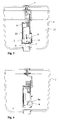
- FIG. 2 shows the drain valve 1 immediately after release of the partial flush.
- the drain valve 1 is now also open and water 17 flows through the opening 3 down into the toilet bowl.
- the water surface 18 is below the upper float 8, so it rests on the closure body 5, which remains in the open position, since it is supported on the lower float 9.
- the water surface 18 thus continues to fall down and finally reaches the lower float 9. If the water surface 18 sinks below this lower float 9, the buoyancy also drops away here and the lower float 9 pivots due to its own weight into the position shown in FIG.
- the closure body 5 is now no longer supported and falls on the valve seat 4.
- the cistern 13 is still only a residual amount of water 17.
- the drain valve 1 is closed. Again, this will not be automatic about this shown inlet valve of the cistern 13 refilled. Finally, the position shown in Figure 1 is reached again.
- the cistern 13 is now ready for a partial flush or full flush.
Abstract
Description
Die Erfindung betrifft ein Ablaufventil für einen Spülkasten mit einem Ventilgehäuse, das eine Auslauföffnung mit einem Ventilsitz aufweist, mit einem Verschlusskörper, der an einem unteren Ende mit dem Ventilsitz zusammenarbeitet, mit einer Zweimengenbetätigungsvorrichtung, mit welcher der Verschlusskörper mit unterschiedlichem Hub anhebbar ist, mit einem oberen zuschaltbaren Schwimmer für eine Teilspülung und einem unteren zuschaltbaren Schwimmer für eine Vollspülung, wobei der obere Schwimmer höhenverstellbar an einem Einstellelement gelagert ist.The invention relates to a drain valve for a cistern with a valve housing having an outlet opening with a valve seat, with a closure body which cooperates at a lower end with the valve seat, with a Zweimengenbetätigungsvorrichtung, with which the closure body can be raised with different stroke, with a upper switchable float for a partial flush and a lower switchable float for a full flush, the upper float is height-adjustable mounted on an adjustment.
Ablaufventile dieser Art ermöglichen eine Zweistufenspülung. Diese ermöglicht eine Teilspülung mit einer Wassermenge, die wesentlich kleiner ist als die im Spülkasten vorhandene Wassermenge. Dadurch ist es möglich, den Wasserverbrauch bei Spülkästen wesentlich zu senken.Drain valves of this type allow a two-stage flush. This allows a partial flush with an amount of water that is much smaller than the amount of water in the cistern. This makes it possible to significantly reduce the water consumption in cisterns.
Ein Ablaufventil dieser Art ist beispielsweise aus der WO 02/059431 bekannt geworden. Bei dieser ist jedoch nachteilig, dass sie aus vergleichsweise vielen beweglichen Einzelteilen besteht und deshalb entsprechend teuer in der Herstellung sowie störanfällig ist.A drain valve of this type has become known for example from WO 02/059431. In this, however, is disadvantageous that it consists of comparatively many moving parts and therefore is correspondingly expensive to manufacture and prone to failure.
Der Erfindung liegt die Aufgabe zugrunde, ein Ablaufventil der genannten Art zu schaffen, das aus weniger Einzelteilen und kostengünstiger herstellbar ist. Das Ablaufventil soll trotzdem funktionssicher sein.The invention has for its object to provide a drain valve of the type mentioned, which is less expensive and cheaper to produce. The drain valve should still be reliable.
Die Aufgabe ist gemäss Anspruch 1 dadurch gelöst, dass das Einstellelement direkt so mit dem Verschlusskörper gekoppelt ist, dass nach der Auslösung einer Teilspülung der Verschlusskörper auf dem Einstellelement lastet und dass bei der Auslösung einer Vollspülung der Verschlusskörper auf dem zugeschalteten unteren Schwimmer lastet und das Einstellelement vom Verschlusskörper entkoppelt ist.The object is achieved according to
Durch die genannte direkte Kupplung des Einstellelementes mit dem Verschlusskörper ergibt sich eine überraschend wesentlich einfachere Konstruktion und auf bisher notwendige bewegliche Teile kann verzichtet werden.By said direct coupling of the adjustment with the closure body results in a surprisingly much simpler construction and previously required moving parts can be dispensed with.
Nach einer Weiterbildung der Erfindung ist vorgesehen, dass das Einstellelement einen unteren Anschlag aufweist, mit dem bei einer Teilspülung der Verschlusskörper mit dem oberen Schwimmer gekoppelt wird. Ein solcher Anschlag kann sehr einfach und kostengünstig, beispielsweise durch eine Verdickung des unteren Endes des Einstellelementes realisiert werden.According to a development of the invention, it is provided that the adjusting element has a lower stop, with which in a partial flushing of the closure body is coupled to the upper float. Such a stop can be realized very easily and inexpensively, for example, by a thickening of the lower end of the adjustment.
Nach einer Weiterbildung der Erfindung ist vorgesehen, dass der untere Schwimmer Mittel für eine Hubbegrenzung aufweist. Eine solche Hubbegrenzung kann in besonders einfacher Weise insbesondere durch eine Nase am unteren Schwimmer realisiert werden, welche mit einer Schulter an einer Kulisse des Verschlussrohres zusammenarbeitet.According to a development of the invention, it is provided that the lower float has means for a stroke limitation. Such a stroke limitation can be realized in a particularly simple manner, in particular by a nose on the lower float, which cooperates with a shoulder on a backdrop of the closure tube.
Nach einer Weiterbildung der Erfindung ist vorgesehen, dass ein Lagerteil des Verschlusskörpers am Einstellelement hochgleiten kann, ohne dass hierbei der obere Schwimmer wirksam wird. Nach einer Weiterbildung der Erfindung wird dies durch einen Toleranzbereich am unteren Ende des Einstellelementes realisiert.According to a development of the invention, it is provided that a bearing part of the closure body can slide up on the adjusting element without the upper float becoming effective. According to a development of the invention, this is realized by a tolerance range at the lower end of the adjustment.
Weitere vorteilhafte Merkmale ergeben sich aus den abhängigen Patentansprüchen, der nachfolgenden Beschreibung sowie der Zeichnung.Further advantageous features emerge from the dependent claims, the following description and the drawings.
Ein Ausführungsbeispiel der Erfindung wird anhand der Zeichnung näher erläutert. Es zeigen:
Figur 1- schematisch eine Ansicht eines teilweise geschnittenen Ablaufventils in der geschlossenen Stellung bei vollständig gefülltem Spülkasten,
Figur 2- das Ablaufventil gemäss
Figur 1, jedoch nach Auslösung einer Teilspülung, Figur 3- das Ablaufventil nach der Auslösung einer Vollspülung und
Figur 4- das Ablaufventil in geschlossener Stellung nach einer Spülung und entleertem Spülkasten.
- FIG. 1
- schematically a view of a partially cut drain valve in the closed position with fully filled cistern,
- FIG. 2
- the drain valve according to FIG. 1, but after triggering of a partial flush,
- FIG. 3
- the drain valve after the triggering of a full flush and
- FIG. 4
- the drain valve in the closed position after a flush and emptied cistern.
Die Figur 1 zeigt einen Spülkasten 13, in dem ein Ablaufventil 1 montiert ist. Das Ablaufventil 1 besitzt ein Gehäuse 2, das an einem unteren Ende einen Stutzen 21 besitzt, der in bekannter Weise am Boden 22a eines Kastenkörpers 22 befestigt ist und der eine Auslauföffnung 3 mit einem Ventilsitz 4 bildet. Der Ventilsitz 4 arbeitet mit einem Verschlusskörper 5 zusammen, der als Ventilrohr ausgebildet ist und der mit einem Zuggestänge 14 zur Auslösung einer Spülung anhebbar ist. Das Zuggestänge 14 ist an einer Zweimengenbetätigungsvorrichtung 7 angeordnet und greift wie ersichtlich am Verschlusskörper 5 an. Die Zweimengenbetätigungsvorrichtung 7 weist beispielsweise Tasten 12 und Drücker 15 auf. Eine solche geeignete Betätigung ist beispielsweise aus der WO 01/46528 des Anmelders bekannt geworden. Mit dieser sind zwei unterschiedliche Hubbewegungen möglich. Bei einem ersten Hub für eine Teilspülung wird der Verschlusskörper 5 weniger hoch angehoben als bei der Auslösung einer Vollspülung. Entsprechend wird bei einer Teilspülung ein zweiarmiger Hebel 14a des Zuggestänges 14 um einen kleineren Winkel verschwenkt als im Fall einer Vollspülung.1 shows a
In der Figur 1 ist der Kastenkörper 22 mit Spülwasser 17 gefüllt. Die Wasseroberfläche 18 befindet sich hierbei unterhalb einer Überlauföffnung 5a des Verschlusskörpers 15. Die Wassermenge, die im Spülkasten 13 vorhanden ist, beträgt beispielsweise 9 oder 6 Liter.In the figure 1, the
Der Verschlusskörper 5 besitzt im Bereich eines unteren Endes 6 einen angeformten Steg 19, der wie ersichtlich radial vorragt und der für ein Einstellelement 10 ein Lagerteil bzw. Kupplungsteil bildet. Der Steg 19 besitzt einen Durchgang 19a, in den das Einstellelement 10 mit einem Toleranzbereich 10d hindurchragt. Am unteren Ende des Toleranzbereiches 10d ist ein Anschlag 10b angeordnet, der hier als Verdickung ausgebildet ist. Über dem Toleranzbereich 10d weist das Einstellelement 10 ein Gewinde 10c auf, in das ein oberer Schwimmer 8 eingeschraubt ist. Durch Drehen des Einstellelementes 10 kann der obere Schwimmer 8 stufenlos in seiner Höhe verstellt werden. Das Einstellelement 10 besitzt zudem ein oberes Ende 10a, das in ein Führungselement 16 verschieblich hineinragt. Das Einstellelement 10 ist wie ersichtlich stabförmig ausgebildet und dient dazu, bei einer Teilspülung den oberen Schwimmer 8 mit dem Verschlusskörper 5 zu koppeln.The
Die Verbindung zwischen dem Einstellelement 10 und dem Steg 19 bzw. dem Verschlusskörper 5 ist jedoch entsprechend dem Toleranzbereich 10d lose.However, the connection between the adjusting
Am Gehäuse 2 ist ein unterer Schwimmer 9 schwenkbar gelagert. Die Lagerung des unteren Schwimmers 9 am Gehäuse 2 erfolgt mit einer am Gehäuse 2 befestigten Schwenkachse 9b.On the
An einem oberen Ende des unteren Schwimmers 9 ist eine Nase 9a angeformt, die mit einer am Verschlusskörper 5 angeformten Kulisse 20 zusammenarbeitet. Diese Kulisse 20 besitzt einen Anschlag 20a, der ebenfalls als seitlich vorspringende Nase oder Schulter ausgebildet ist. Der Anschlag 20a hat eine doppelte Funktion. Im einen Fall begrenzt der Anschlag 20a den Hub des Verschlusskörpers 5 und im anderen Fall wird der Verschlusskörper 5 am unteren Schwimmer 9 abgestützt.At an upper end of the
Nachfolgend wird die Wirkungsweise des erfindungsgemässen Ablaufventils näher erläutert.The operation of the inventive drain valve will be explained in more detail.
Zur Auslösung einer Teilspülung wird durch Drücken der entsprechenden Tasten 12 der Verschlusskörper 5 in die in Figur 2 gezeigte Stellung angehoben. Durch den Auftrieb des oberen Schwimmers 8 wird das Einstellelement 10 ebenfalls angehoben, bis das untere Ende 10b unten am Steg 19 anliegt. Ein weiterer Auftrieb des Verschlusskörpers 5 wird durch den unteren Schwimmer 9 verhindert, welcher mit der Nase 9a oben auf dem Anschlag 20a anliegt. Die Figur 2 zeigt das Ablaufventil 1 unmittelbar nach Auslösung der Teilspülung. Durch den Auftrieb des oberen Schwimmers 8 wird der Verschlusskörper 5 in der in Figur 2 gezeigten Stellung gehalten. Da der Verschlusskörper 5 vom Ventilsitz 4 abgehoben ist, ist das Ventil offen und Wasser 17 strömt durch die Öffnung 3 in eine hier nicht gezeigte WC-Schüssel. Entsprechend sinkt die Wasseroberfläche 18. Befindet sich nun die Wasseroberfläche 18 unterhalb des oberen Schwimmers 8, so fällt der Auftrieb durch diesen oberen Schwimmer 8 weg und der Verschlusskörper 5 fällt auf den Ventilsitz 4. Das Ablaufventil 1 ist damit geschlossen. Da der Kastenkörper 22 nur teilweise entleert ist, befindet sich im Kastenkörper 22 noch Wasser 17, beispielsweise 3 oder 6 Liter. Über ein hier nicht gezeigtes an sich bekanntes Einlaufventil wird nun der Kastenkörper 22 wieder gefüllt, bis das in Figur 1 gezeigte Wasserniveau erreicht ist.To trigger a partial flush is lifted by pressing the
Bei der Auslösung einer Vollspülung, bei welcher beispielsweise mit 6 oder 9 Litern gespült wird, wird der Verschlusskörper 5 in die in Figur 3 gezeigte Stellung angehoben. Der Hub ist hier etwas grösser als bei der Auslösung einer Teilspülung. Der obere Schwimmer 8 wird durch den Auftrieb mit dem Einstellelement 10 ebenfalls angehoben. Durch einen hier nicht gezeigten Anschlag des oberen Schwimmers 8 am Ventilgehäuse 2 ist die in Figur 3 gezeigte Stellung bestimmt. Beim Anheben des Verschlusskörpers 5 gleitet die Nase 9a an der Kulisse 20 entlang und erreicht schliesslich die in Figur 3 gezeigte Position, in welcher sich die Nase 9a unterhalb des Anschlags 20a befindet. Der Steg 19 befindet sich in dieser Stellung über dem unteren Ende 10b des Einstellelementes 10 und damit im oberen Teil des Toleranzbereiches 10d. Der Verschlusskörper 5 lastet nun auf dem unteren Schwimmer 9, während der obere Schwimmer 8 unwirksam ist. Das Ablaufventil 1 ist nun ebenfalls offen und Wasser 17 strömt durch die Öffnung 3 nach unten in die Klosettschüssel. Befindet sich die Wasseroberfläche 18 unterhalb des oberen Schwimmers 8, so lastet dieser auf dem Verschlusskörper 5, der jedoch in der offenen Stellung verharrt, da er am unteren Schwimmer 9 abgestützt ist. Die Wasseroberfläche 18 sinkt damit weiter nach unten und erreicht schliesslich den unteren Schwimmer 9. Sinkt die Wasseroberfläche 18 unter diesen unteren Schwimmer 9, so fällt auch hier der Auftrieb weg und der untere Schwimmer 9 schwenkt aufgrund seines Eigengewichtes in die in Figur 4 gezeigte Stellung. Der Verschlusskörper 5 ist nun nicht mehr unterstützt und fällt auf den Ventilsitz 4. Im Spülkasten 13 befindet sich lediglich noch eine Restmenge des Wassers 17. Das Ablaufventil 1 ist damit geschlossen. Wiederum wird automatisch über das hier nicht gezeigte Einlaufventil der Spülkasten 13 nachgefüllt. Schliesslich wird wieder die in Figur 1 gezeigte Stellung erreicht. Der Spülkasten 13 ist nun wieder für eine Teilspülung oder Vollspülung bereit.When triggering a full flush, in which, for example, is purged with 6 or 9 liters, the
- 11
- Ablaufventildrain valve
- 22
- Ventilgehäusevalve housing
- 33
- Auslauföffnungoutlet opening
- 44
- Ventilsitzvalve seat
- 55
- Verschlusskörper (Ventilrohr)Closure body (valve tube)
- 5a5a
- ÜberlauföffnungOverflow opening
- 66
- EndeThe End
- 77
- ZweimengenbetätigungsvorrichtungDual flush actuator
- 88th
- oberer Schwimmerupper float
- 99
- unterer Schwimmerlower swimmer
- 9a9a
- Nasenose
- 9b9b
- Schwenkachseswivel axis
- 1010
- Einstellelement (Einstellschraube)Adjustment element (adjusting screw)
- 10a10a
- oberes Endetop end
- 10b10b
- unteres Endelower end
- 10c10c
- Gewindethread
- 10d10d
- Toleranzbereichtolerance
- 1111
- Spülkastendeckelcistern
- 1212
- Betätigungstasteactuating button
- 1313
- Spülkastencistern
- 1414
- Zuggestängepull line
- 14a14a
- Hebellever
- 1515
- Drückerhandle
- 1616
- Führungselementguide element
- 1717
- Wasserwater
- 1818
- Wasseroberflächewater surface
- 1919
- Stegweb
- 19a19a
- Durchgangpassage
- 2020
- Kulissescenery
- 20a20a
- Anschlagattack
- 2121
- StutzenSupport
- 2222
- Kastenkörperbox body
- 22a22a
- Bodenground
Claims (9)
Priority Applications (6)
| Application Number | Priority Date | Filing Date | Title |
|---|---|---|---|
| ES04405772T ES2325688T3 (en) | 2004-12-15 | 2004-12-15 | DRAIN VALVE FOR A DISCHARGE DEPOSIT. |
| PL04405772T PL1672130T3 (en) | 2004-12-15 | 2004-12-15 | Flush device for a lavatory flush tank |
| SI200431196T SI1672130T1 (en) | 2004-12-15 | 2004-12-15 | Flush device for a lavatory flush tank |
| EP04405772A EP1672130B1 (en) | 2004-12-15 | 2004-12-15 | Flush device for a lavatory flush tank |
| AT04405772T ATE430848T1 (en) | 2004-12-15 | 2004-12-15 | DRAIN VALVE FOR A CIstern |
| DE502004009463T DE502004009463D1 (en) | 2004-12-15 | 2004-12-15 | Drain valve for a cistern |
Applications Claiming Priority (1)
| Application Number | Priority Date | Filing Date | Title |
|---|---|---|---|
| EP04405772A EP1672130B1 (en) | 2004-12-15 | 2004-12-15 | Flush device for a lavatory flush tank |
Publications (2)
| Publication Number | Publication Date |
|---|---|
| EP1672130A1 true EP1672130A1 (en) | 2006-06-21 |
| EP1672130B1 EP1672130B1 (en) | 2009-05-06 |
Family
ID=34932405
Family Applications (1)
| Application Number | Title | Priority Date | Filing Date |
|---|---|---|---|
| EP04405772A Active EP1672130B1 (en) | 2004-12-15 | 2004-12-15 | Flush device for a lavatory flush tank |
Country Status (6)
| Country | Link |
|---|---|
| EP (1) | EP1672130B1 (en) |
| AT (1) | ATE430848T1 (en) |
| DE (1) | DE502004009463D1 (en) |
| ES (1) | ES2325688T3 (en) |
| PL (1) | PL1672130T3 (en) |
| SI (1) | SI1672130T1 (en) |
Cited By (6)
| Publication number | Priority date | Publication date | Assignee | Title |
|---|---|---|---|---|
| EP1916343A2 (en) | 2006-10-17 | 2008-04-30 | VIEGA GmbH & Co. KG. | Dual flush valve |
| EP2006458A1 (en) * | 2007-06-19 | 2008-12-24 | Geberit Technik Ag | Drain valve for a cistern |
| CN102691343A (en) * | 2012-06-18 | 2012-09-26 | 北京建筑工程学院 | Pedestal pan flushing device with flow regulation function |
| EP2505727A1 (en) | 2011-03-30 | 2012-10-03 | Geberit International AG | Drain valve for a cistern |
| EP3321434A1 (en) * | 2016-11-09 | 2018-05-16 | Geberit International AG | Drainage fitting |
| DE102017131401A1 (en) | 2017-12-28 | 2019-07-04 | Lixil International Pte. Ltd. | HEIGHT ADJUSTABLE TUBE CAGE UNIT |
Families Citing this family (1)
| Publication number | Priority date | Publication date | Assignee | Title |
|---|---|---|---|---|
| ES2436649B1 (en) * | 2012-06-28 | 2014-08-07 | Roca Sanitario, S. A. | Toilet loading and unloading device |
Citations (3)
| Publication number | Priority date | Publication date | Assignee | Title |
|---|---|---|---|---|
| WO2001046528A1 (en) | 1999-12-21 | 2001-06-28 | Geberit Technik Ag | Actuating device for the drain valve of a cistern |
| WO2002059431A1 (en) | 2001-01-23 | 2002-08-01 | Societe Etex De Recherches Techniques, S.E.R.T. | Flushing mechanism for toilet tank |
| EP1428945A2 (en) * | 2002-12-12 | 2004-06-16 | Polypipe Bathroom & Kitchen Products Ltd. | Float valve assembly |
-
2004
- 2004-12-15 EP EP04405772A patent/EP1672130B1/en active Active
- 2004-12-15 SI SI200431196T patent/SI1672130T1/en unknown
- 2004-12-15 DE DE502004009463T patent/DE502004009463D1/en not_active Expired - Fee Related
- 2004-12-15 AT AT04405772T patent/ATE430848T1/en not_active IP Right Cessation
- 2004-12-15 ES ES04405772T patent/ES2325688T3/en active Active
- 2004-12-15 PL PL04405772T patent/PL1672130T3/en unknown
Patent Citations (3)
| Publication number | Priority date | Publication date | Assignee | Title |
|---|---|---|---|---|
| WO2001046528A1 (en) | 1999-12-21 | 2001-06-28 | Geberit Technik Ag | Actuating device for the drain valve of a cistern |
| WO2002059431A1 (en) | 2001-01-23 | 2002-08-01 | Societe Etex De Recherches Techniques, S.E.R.T. | Flushing mechanism for toilet tank |
| EP1428945A2 (en) * | 2002-12-12 | 2004-06-16 | Polypipe Bathroom & Kitchen Products Ltd. | Float valve assembly |
Cited By (10)
| Publication number | Priority date | Publication date | Assignee | Title |
|---|---|---|---|---|
| EP1916343A2 (en) | 2006-10-17 | 2008-04-30 | VIEGA GmbH & Co. KG. | Dual flush valve |
| EP1916343A3 (en) * | 2006-10-17 | 2010-04-28 | VIEGA GmbH & Co. KG. | Dual flush valve |
| EP2006458A1 (en) * | 2007-06-19 | 2008-12-24 | Geberit Technik Ag | Drain valve for a cistern |
| CN101328718B (en) * | 2007-06-19 | 2010-09-29 | 吉博力国际股份公司 | Drain valve for a cistern |
| US7996927B2 (en) | 2007-06-19 | 2011-08-16 | Geberit Technik Ag | Discharge valve for a flushing cistern |
| AU2008201972B2 (en) * | 2007-06-19 | 2014-02-13 | Geberit International Ag | Discharge valve for a flushing cistern |
| EP2505727A1 (en) | 2011-03-30 | 2012-10-03 | Geberit International AG | Drain valve for a cistern |
| CN102691343A (en) * | 2012-06-18 | 2012-09-26 | 北京建筑工程学院 | Pedestal pan flushing device with flow regulation function |
| EP3321434A1 (en) * | 2016-11-09 | 2018-05-16 | Geberit International AG | Drainage fitting |
| DE102017131401A1 (en) | 2017-12-28 | 2019-07-04 | Lixil International Pte. Ltd. | HEIGHT ADJUSTABLE TUBE CAGE UNIT |
Also Published As
| Publication number | Publication date |
|---|---|
| PL1672130T3 (en) | 2009-10-30 |
| DE502004009463D1 (en) | 2009-06-18 |
| ATE430848T1 (en) | 2009-05-15 |
| EP1672130B1 (en) | 2009-05-06 |
| SI1672130T1 (en) | 2009-10-31 |
| ES2325688T3 (en) | 2009-09-14 |
Similar Documents
| Publication | Publication Date | Title |
|---|---|---|
| EP1719844B1 (en) | Flush valve for a flush cistern | |
| EP0722020B1 (en) | Flushing device in a flushing tank | |
| EP0589836B1 (en) | Flush valve for a WC cistern | |
| DE8418215U1 (en) | ACTUATING DEVICE FOR THE DRAIN VALVE OF A Cistern | |
| DE2753929A1 (en) | WATER SAVING VALVE DEVICE FOR THE FLUSHBOX OF WATER TOOLS | |
| EP2006458B1 (en) | Drain valve for a cistern | |
| EP1672130B1 (en) | Flush device for a lavatory flush tank | |
| EP2092128B1 (en) | Two-quantity discharge valve | |
| EP1995386A1 (en) | Actuating device for discharge fittings and discharge fittings with such an actuating device and method for mounting such discharge fittings | |
| EP1197607B1 (en) | Flushing cistern for a WC | |
| DE60319174T2 (en) | Quick-closing inlet valve for a toilet cistern | |
| DE3108791A1 (en) | Discharge valve on a sanitary facility | |
| CH670850A5 (en) | ||
| EP1580338B1 (en) | Flush valve for a flushing cistern | |
| DE2326877A1 (en) | CISTERN | |
| EP1010826B1 (en) | Outlet device for a flushing cistern | |
| EP0962600A2 (en) | Outlet device for a flushing cistern | |
| DE102008028610B4 (en) | Fluid valve with timer | |
| CH687048A5 (en) | Discharge regulator especially for receiving a rainwater Rueckhaltebecken. | |
| EP0955417B1 (en) | Flushing device for a toilet flushing cistern | |
| DE8400686U1 (en) | DRAIN SET WITH LOCKING DEVICE | |
| WO2023186462A1 (en) | Cistern, in particular flush-mounted cistern, for a toilet or urinal | |
| EP0859093B1 (en) | Outlet device for a toilet flush tank with selective full or partial flush | |
| DE313898C (en) | ||
| EP0715033A1 (en) | Flushing device in a water closet flushing reservoir |
Legal Events
| Date | Code | Title | Description |
|---|---|---|---|
| PUAI | Public reference made under article 153(3) epc to a published international application that has entered the european phase |
Free format text: ORIGINAL CODE: 0009012 |
|
| AK | Designated contracting states |
Kind code of ref document: A1 Designated state(s): AT BE BG CH CY CZ DE DK EE ES FI FR GB GR HU IE IS IT LI LT LU MC NL PL PT RO SE SI SK TR |
|
| AX | Request for extension of the european patent |
Extension state: AL BA HR LV MK YU |
|
| 17P | Request for examination filed |
Effective date: 20060704 |
|
| 17Q | First examination report despatched |
Effective date: 20060925 |
|
| AKX | Designation fees paid |
Designated state(s): AT BE BG CH CY CZ DE DK EE ES FI FR GB GR HU IE IS IT LI LT LU MC NL PL PT RO SE SI SK TR |
|
| GRAP | Despatch of communication of intention to grant a patent |
Free format text: ORIGINAL CODE: EPIDOSNIGR1 |
|
| GRAS | Grant fee paid |
Free format text: ORIGINAL CODE: EPIDOSNIGR3 |
|
| GRAA | (expected) grant |
Free format text: ORIGINAL CODE: 0009210 |
|
| AK | Designated contracting states |
Kind code of ref document: B1 Designated state(s): AT BE BG CH CY CZ DE DK EE ES FI FR GB GR HU IE IS IT LI LT LU MC NL PL PT RO SE SI SK TR |
|
| REG | Reference to a national code |
Ref country code: GB Ref legal event code: FG4D Free format text: NOT ENGLISH |
|
| REG | Reference to a national code |
Ref country code: CH Ref legal event code: EP |
|
| REG | Reference to a national code |
Ref country code: IE Ref legal event code: FG4D |
|
| REF | Corresponds to: |
Ref document number: 502004009463 Country of ref document: DE Date of ref document: 20090618 Kind code of ref document: P |
|
| REG | Reference to a national code |
Ref country code: ES Ref legal event code: FG2A Ref document number: 2325688 Country of ref document: ES Kind code of ref document: T3 |
|
| PG25 | Lapsed in a contracting state [announced via postgrant information from national office to epo] |
Ref country code: LT Free format text: LAPSE BECAUSE OF FAILURE TO SUBMIT A TRANSLATION OF THE DESCRIPTION OR TO PAY THE FEE WITHIN THE PRESCRIBED TIME-LIMIT Effective date: 20090506 Ref country code: FI Free format text: LAPSE BECAUSE OF FAILURE TO SUBMIT A TRANSLATION OF THE DESCRIPTION OR TO PAY THE FEE WITHIN THE PRESCRIBED TIME-LIMIT Effective date: 20090506 |
|
| REG | Reference to a national code |
Ref country code: PL Ref legal event code: T3 |
|
| NLV1 | Nl: lapsed or annulled due to failure to fulfill the requirements of art. 29p and 29m of the patents act | ||
| PG25 | Lapsed in a contracting state [announced via postgrant information from national office to epo] |
Ref country code: SE Free format text: LAPSE BECAUSE OF FAILURE TO SUBMIT A TRANSLATION OF THE DESCRIPTION OR TO PAY THE FEE WITHIN THE PRESCRIBED TIME-LIMIT Effective date: 20090806 Ref country code: NL Free format text: LAPSE BECAUSE OF FAILURE TO SUBMIT A TRANSLATION OF THE DESCRIPTION OR TO PAY THE FEE WITHIN THE PRESCRIBED TIME-LIMIT Effective date: 20090506 Ref country code: IS Free format text: LAPSE BECAUSE OF FAILURE TO SUBMIT A TRANSLATION OF THE DESCRIPTION OR TO PAY THE FEE WITHIN THE PRESCRIBED TIME-LIMIT Effective date: 20090906 |
|
| REG | Reference to a national code |
Ref country code: HU Ref legal event code: AG4A Ref document number: E005998 Country of ref document: HU |
|
| REG | Reference to a national code |
Ref country code: IE Ref legal event code: FD4D |
|
| PG25 | Lapsed in a contracting state [announced via postgrant information from national office to epo] |
Ref country code: EE Free format text: LAPSE BECAUSE OF FAILURE TO SUBMIT A TRANSLATION OF THE DESCRIPTION OR TO PAY THE FEE WITHIN THE PRESCRIBED TIME-LIMIT Effective date: 20090506 Ref country code: DK Free format text: LAPSE BECAUSE OF FAILURE TO SUBMIT A TRANSLATION OF THE DESCRIPTION OR TO PAY THE FEE WITHIN THE PRESCRIBED TIME-LIMIT Effective date: 20090506 Ref country code: RO Free format text: LAPSE BECAUSE OF FAILURE TO SUBMIT A TRANSLATION OF THE DESCRIPTION OR TO PAY THE FEE WITHIN THE PRESCRIBED TIME-LIMIT Effective date: 20090506 Ref country code: IE Free format text: LAPSE BECAUSE OF FAILURE TO SUBMIT A TRANSLATION OF THE DESCRIPTION OR TO PAY THE FEE WITHIN THE PRESCRIBED TIME-LIMIT Effective date: 20090506 |
|
| REG | Reference to a national code |
Ref country code: GB Ref legal event code: 732E Free format text: REGISTERED BETWEEN 20100121 AND 20100127 |
|
| PLBE | No opposition filed within time limit |
Free format text: ORIGINAL CODE: 0009261 |
|
| STAA | Information on the status of an ep patent application or granted ep patent |
Free format text: STATUS: NO OPPOSITION FILED WITHIN TIME LIMIT |
|
| 26N | No opposition filed |
Effective date: 20100209 |
|
| REG | Reference to a national code |
Ref country code: HU Ref legal event code: GB9C Owner name: GEBERIT INTERNATIONAL AG, DE Free format text: FORMER OWNER(S): GEBERIT TECHNIK AG, CH Ref country code: HU Ref legal event code: FH1C Free format text: FORMER REPRESENTATIVE(S): DR. JAKAB JUDIT, S.B.G. & K. SZABADALMI UEGYVIVOEI IRODA, HU Representative=s name: S.B.G. & K. SZABADALMI ES UEGYVEDI IRODAK, HU |
|
| REG | Reference to a national code |
Ref country code: SI Ref legal event code: SP73 Owner name: GEBERIT INTERNATIONAL AG; CH Effective date: 20100324 |
|
| REG | Reference to a national code |
Ref country code: SK Ref legal event code: PC4A Ref document number: E 5746 Country of ref document: SK Owner name: GEBERIT INTERNATIONAL AG, JONA, CH Free format text: FORMER OWNER: GEBERIT TECHNIK AG, JONA, CH Effective date: 20100219 |
|
| BERE | Be: lapsed |
Owner name: GEBERIT TECHNIK A.G. Effective date: 20091231 |
|
| REG | Reference to a national code |
Ref country code: FR Ref legal event code: TP |
|
| PG25 | Lapsed in a contracting state [announced via postgrant information from national office to epo] |
Ref country code: MC Free format text: LAPSE BECAUSE OF NON-PAYMENT OF DUE FEES Effective date: 20100701 |
|
| REG | Reference to a national code |
Ref country code: CH Ref legal event code: PL |
|
| PG25 | Lapsed in a contracting state [announced via postgrant information from national office to epo] |
Ref country code: LI Free format text: LAPSE BECAUSE OF NON-PAYMENT OF DUE FEES Effective date: 20091231 Ref country code: GR Free format text: LAPSE BECAUSE OF FAILURE TO SUBMIT A TRANSLATION OF THE DESCRIPTION OR TO PAY THE FEE WITHIN THE PRESCRIBED TIME-LIMIT Effective date: 20090807 Ref country code: BE Free format text: LAPSE BECAUSE OF NON-PAYMENT OF DUE FEES Effective date: 20091231 Ref country code: CH Free format text: LAPSE BECAUSE OF NON-PAYMENT OF DUE FEES Effective date: 20091231 |
|
| PG25 | Lapsed in a contracting state [announced via postgrant information from national office to epo] |
Ref country code: DE Free format text: LAPSE BECAUSE OF NON-PAYMENT OF DUE FEES Effective date: 20100701 |
|
| PG25 | Lapsed in a contracting state [announced via postgrant information from national office to epo] |
Ref country code: IT Free format text: LAPSE BECAUSE OF FAILURE TO SUBMIT A TRANSLATION OF THE DESCRIPTION OR TO PAY THE FEE WITHIN THE PRESCRIBED TIME-LIMIT Effective date: 20090506 |
|
| PG25 | Lapsed in a contracting state [announced via postgrant information from national office to epo] |
Ref country code: LU Free format text: LAPSE BECAUSE OF NON-PAYMENT OF DUE FEES Effective date: 20091215 |
|
| PG25 | Lapsed in a contracting state [announced via postgrant information from national office to epo] |
Ref country code: AT Free format text: LAPSE BECAUSE OF NON-PAYMENT OF DUE FEES Effective date: 20091215 |
|
| PG25 | Lapsed in a contracting state [announced via postgrant information from national office to epo] |
Ref country code: CY Free format text: LAPSE BECAUSE OF FAILURE TO SUBMIT A TRANSLATION OF THE DESCRIPTION OR TO PAY THE FEE WITHIN THE PRESCRIBED TIME-LIMIT Effective date: 20090506 |
|
| PGFP | Annual fee paid to national office [announced via postgrant information from national office to epo] |
Ref country code: BG Payment date: 20111215 Year of fee payment: 8 |
|
| PG25 | Lapsed in a contracting state [announced via postgrant information from national office to epo] |
Ref country code: BG Free format text: LAPSE BECAUSE OF NON-PAYMENT OF DUE FEES Effective date: 20121231 Ref country code: PT Free format text: LAPSE BECAUSE OF NON-PAYMENT OF DUE FEES Effective date: 20090906 |
|
| PGFP | Annual fee paid to national office [announced via postgrant information from national office to epo] |
Ref country code: HU Payment date: 20141219 Year of fee payment: 11 |
|
| REG | Reference to a national code |
Ref country code: FR Ref legal event code: PLFP Year of fee payment: 12 |
|
| PG25 | Lapsed in a contracting state [announced via postgrant information from national office to epo] |
Ref country code: HU Free format text: LAPSE BECAUSE OF NON-PAYMENT OF DUE FEES Effective date: 20151216 |
|
| REG | Reference to a national code |
Ref country code: FR Ref legal event code: PLFP Year of fee payment: 13 |
|
| REG | Reference to a national code |
Ref country code: FR Ref legal event code: PLFP Year of fee payment: 14 |
|
| PGFP | Annual fee paid to national office [announced via postgrant information from national office to epo] |
Ref country code: CZ Payment date: 20171127 Year of fee payment: 14 Ref country code: SK Payment date: 20171214 Year of fee payment: 14 Ref country code: TR Payment date: 20171213 Year of fee payment: 14 |
|
| PG25 | Lapsed in a contracting state [announced via postgrant information from national office to epo] |
Ref country code: CZ Free format text: LAPSE BECAUSE OF NON-PAYMENT OF DUE FEES Effective date: 20181215 |
|
| REG | Reference to a national code |
Ref country code: SK Ref legal event code: MM4A Ref document number: E 5746 Country of ref document: SK Effective date: 20181215 |
|
| PG25 | Lapsed in a contracting state [announced via postgrant information from national office to epo] |
Ref country code: SK Free format text: LAPSE BECAUSE OF NON-PAYMENT OF DUE FEES Effective date: 20181215 |
|
| PGFP | Annual fee paid to national office [announced via postgrant information from national office to epo] |
Ref country code: GB Payment date: 20211222 Year of fee payment: 18 Ref country code: FR Payment date: 20211224 Year of fee payment: 18 |
|
| PGFP | Annual fee paid to national office [announced via postgrant information from national office to epo] |
Ref country code: SI Payment date: 20211207 Year of fee payment: 18 |
|
| PGFP | Annual fee paid to national office [announced via postgrant information from national office to epo] |
Ref country code: PL Payment date: 20211119 Year of fee payment: 18 |
|
| PGFP | Annual fee paid to national office [announced via postgrant information from national office to epo] |
Ref country code: ES Payment date: 20220218 Year of fee payment: 18 |
|
| PG25 | Lapsed in a contracting state [announced via postgrant information from national office to epo] |
Ref country code: TR Free format text: LAPSE BECAUSE OF NON-PAYMENT OF DUE FEES Effective date: 20181215 |
|
| GBPC | Gb: european patent ceased through non-payment of renewal fee |
Effective date: 20221215 |
|
| REG | Reference to a national code |
Ref country code: SI Ref legal event code: KO00 Effective date: 20230810 |
|
| PG25 | Lapsed in a contracting state [announced via postgrant information from national office to epo] |
Ref country code: GB Free format text: LAPSE BECAUSE OF NON-PAYMENT OF DUE FEES Effective date: 20221215 |
|
| PG25 | Lapsed in a contracting state [announced via postgrant information from national office to epo] |
Ref country code: SI Free format text: LAPSE BECAUSE OF NON-PAYMENT OF DUE FEES Effective date: 20221216 Ref country code: FR Free format text: LAPSE BECAUSE OF NON-PAYMENT OF DUE FEES Effective date: 20221231 |
|
| REG | Reference to a national code |
Ref country code: ES Ref legal event code: FD2A Effective date: 20240130 |