EP2505727A1 - Drain valve for a cistern - Google Patents
Drain valve for a cistern Download PDFInfo
- Publication number
- EP2505727A1 EP2505727A1 EP11160456A EP11160456A EP2505727A1 EP 2505727 A1 EP2505727 A1 EP 2505727A1 EP 11160456 A EP11160456 A EP 11160456A EP 11160456 A EP11160456 A EP 11160456A EP 2505727 A1 EP2505727 A1 EP 2505727A1
- Authority
- EP
- European Patent Office
- Prior art keywords
- damping
- closure body
- rinsing
- cavity
- cistern
- Prior art date
- Legal status (The legal status is an assumption and is not a legal conclusion. Google has not performed a legal analysis and makes no representation as to the accuracy of the status listed.)
- Granted
Links
Images


Classifications
-
- E—FIXED CONSTRUCTIONS
- E03—WATER SUPPLY; SEWERAGE
- E03D—WATER-CLOSETS OR URINALS WITH FLUSHING DEVICES; FLUSHING VALVES THEREFOR
- E03D1/00—Water flushing devices with cisterns ; Setting up a range of flushing devices or water-closets; Combinations of several flushing devices
- E03D1/02—High-level flushing systems
- E03D1/14—Cisterns discharging variable quantities of water also cisterns with bell siphons in combination with flushing valves
- E03D1/142—Cisterns discharging variable quantities of water also cisterns with bell siphons in combination with flushing valves in cisterns with flushing valves
- E03D1/144—Cisterns discharging variable quantities of water also cisterns with bell siphons in combination with flushing valves in cisterns with flushing valves having a single flush outlet and an additional float for delaying the valve closure
-
- E—FIXED CONSTRUCTIONS
- E03—WATER SUPPLY; SEWERAGE
- E03D—WATER-CLOSETS OR URINALS WITH FLUSHING DEVICES; FLUSHING VALVES THEREFOR
- E03D1/00—Water flushing devices with cisterns ; Setting up a range of flushing devices or water-closets; Combinations of several flushing devices
- E03D1/30—Valves for high or low level cisterns; Their arrangement ; Flushing mechanisms in the cistern, optionally with provisions for a pre-or a post- flushing and for cutting off the flushing mechanism in case of leakage
- E03D1/308—Valves for high or low level cisterns; Their arrangement ; Flushing mechanisms in the cistern, optionally with provisions for a pre-or a post- flushing and for cutting off the flushing mechanism in case of leakage with articulated valves
-
- E—FIXED CONSTRUCTIONS
- E03—WATER SUPPLY; SEWERAGE
- E03D—WATER-CLOSETS OR URINALS WITH FLUSHING DEVICES; FLUSHING VALVES THEREFOR
- E03D1/00—Water flushing devices with cisterns ; Setting up a range of flushing devices or water-closets; Combinations of several flushing devices
- E03D1/30—Valves for high or low level cisterns; Their arrangement ; Flushing mechanisms in the cistern, optionally with provisions for a pre-or a post- flushing and for cutting off the flushing mechanism in case of leakage
- E03D1/34—Flushing valves for outlets; Arrangement of outlet valves
Definitions
- the present invention relates to a drain valve for a cistern according to the preamble of claim 1.
- Drain fittings or drainage valves for cisterns are known from the prior art.
- such drain fittings comprise a valve seat, which is arranged in front of an outlet opening, through which the rinse water can flow out of the cistern, and a cooperating with this valve seat sealing element of an overflow pipe.
- the overflow pipe is raised and the sealing element is raised equally by the valve seat. Consequently arises between the valve seat and sealing element, a gap through which the water can flow out of the cistern. After flushing the overflow pipe is moved together with the sealing element again against the valve seat, so that the waste set can be closed again.
- the waste set after the EP 1 854 926 could be minimized flushing noise.
- Another waste set is from the EP 1 672 130 known, this drain set allows an intermediate flush.
- the invention has for its object to provide a drain valve, the noise in a flushing is further minimized.
- a drain valve for a cistern comprises a valve housing with an outlet opening and with a valve seat and a closure body which cooperates with the valve seat at a lower end.
- the closure body is displaceable in the valve housing from a closure position, in which the closure body is in fluid-tight contact with the valve seat, into at least one rinsing position, in which the closure body is spaced from the valve seat. After the rinsing process, the closure body is displaceable from the rinsing position into the closed position.
- the drain valve further comprises a hydraulic damping element, which damps the movement of the closure body from the rinsing position to the closure position, so that the movement of the closure body can be delayed before contacting the valve seat.
- damping element damping of the closure body does not hit the valve seat with full force or speed, but is deposited relatively slowly or gently on the valve seat, which leads to a minimization of noise and also to a minimization of the impact force.
- the hydraulic damping element preferably uses rinsing water, which is located in the cistern, as a damping medium. As a result, maintenance of the damping element can largely be avoided or greatly reduced.
- the damping element preferably comprises an integrally formed on the closure body damping surface which at least partially in itself in the cistern or in Valve housing located damping medium is immersed.
- the damping element is a related to the closure body or a molded on the closure body damping plate and filled with a damping medium cavity, wherein in the movement from the rinsing position into the closure position, the absorbed by the cavity damping medium can be displaced or flowed through the damping plate.
- the cavity is filled with a Spülwasserrestmenge, whereby the damping medium consists essentially of rinse water.
- the cavity is provided by a sidewall and a bottom wall of the valve housing.
- the damping medium in the cavity provides a spatially limited area with increased pressure, wherein in the movement from the rinsing position into the closed position, the damping plate or the damping surface are movable through the cavity, so that the cavity located in the damping medium from the through the cavity spatially limited area can be overflowed by a defined cross-section in a zone outside the spatially limited area with lower pressure.
- the cross section is provided in particular by at least one opening through which the water can flow out, wherein the cross section of the opening is preferably adjustable.
- the free cross-section or opening necessary for this operating principle can be achieved in a preferred embodiment by the difference between the area of the damping plate and the surrounding spatial separation of the chamber for the damping medium.
- the opening can also be provided both as a passage from the cavity and / or as an opening in the damping plate. Due to the adjustability of the cross section, the damping effect can be adjusted.
- the at least one opening is preferably arranged such that the water can be flowed out of the cavity in a vertical and / or horizontal and / or inclined direction to the movement axis of the closure body.
- the damping surface or the damping plate is integrally formed on the closure body, so that a one-piece structure can be provided.
- a Spülwasserrestmenge in the region of the valve housing, wherein damping surface or damping plate immersed in the movement of the flushing position in the closed position either in the Spippowasserrestmenge or already immersed in the Spülwassermenge, the attenuation by the immersion resistance and / or the surface resistance of the moving in the Spülwasserrestmenge moving damping surface or damping plate is provided.
- the closure body preferably has a concavely curved surface which can be flowed through by the rinsing water during the rinsing process, so that a buoyancy force on the closure body results from the rinsing water.
- a suction while air at the same time by an overflow opening through the closure body is nachziehbar, resulting in a gently expiring rinsing.
- a cistern assembly comprises a cistern and a drain valve according to the above description, wherein the drain valve is preferably connected via a drain opening with the cistern.
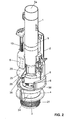
- FIGS. 1 and 2 a perspective view of a drain valve 1 for a cistern, wherein the cistern is not shown in these two views.
- the drain valve 1 essentially comprises a valve housing 2 with an outlet opening 3 and a valve seat 4 and a closure body 5 which cooperates with the valve seat 4 at a lower end 6.
- the closure body 5 rests with the lower end 6 on the valve seat 4.
- the closure body 5 is displaceable in the valve housing 2 from a closure position in which the closure body 5 is in fluidtight contact with the valve seat 4, into at least one rinsing position, in which the closure body 5 is spaced from the valve seat 4.
- the rinsing position which in the FIG. 2 Accordingly, rinsing water can flow out through the gap 34 between the closure body 5 and the valve seat 4.
- the closure body 5 is again in the rinsing position the lock position is displaceable.
- the closure body is in the closed position and in the FIG. 2 and 4 shown in the rinsing position.
- the housing 2 has a nozzle 21 at a lower end, which is here via two oppositely arranged webs 33 with the housing 2 in conjunction.
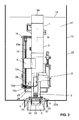
- the nozzle 21 can, as in the FIG. 3 can be fixed in a known manner to the bottom 22a of a box body 22 of a cistern 13.
- the nozzle 21 forms here the outlet opening 3 with the valve seat 4 forms.
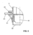
- the closure body 5 has a sealing disk 23 revolving around the closure body 5, which rests on the valve seat 4 in the closed position and thus provides a fluid-tight connection.
- the sealing disc 23 is embedded in a groove 24 on the closure body 5.
- the closure body 5 can be raised with a tie rod, not shown, for triggering a flushing from the closure position into the flushing position.
- the pull rod can be arranged on a dual-quantity actuation device and engages on the closure body 5.
- the dual-quantity operating device has, for example, keys and pushers. Such a suitable operation is for example from the WO 01/46528 or the EP 1 672 130 have become known to the applicant. With this two different strokes are possible. In a first stroke for a partial flush of the closure body 5 is raised less high than when triggering a full flush. Consequently, there are two rinsing positions here, namely one for the partial rinse and one for the full rinse.
- the box body 22 is filled with rinse water 17.
- the water surface 18 is in this case below an overflow opening 5a of the closure body 5.
- the overflow opening 5a extends through the entire closure body 5 and serves for the removal of rinse water, if the water level rises unintentionally.
- the drain valve 1 further comprises a damping element 25, which in particular in of the FIG. 1 easy to recognize.
- the damping element 25 damps the movement of the closure body 5 from the rinsing position into the closure position, so that the movement of the closure body 5 can be delayed before contacting the valve seat 4.
- the damping element 25 has the advantage that the closure body 5 does not impinge on the valve seat 4 at full speed, so that the associated noise development is massively reduced. In particular, the sound of the impact is massively reduced.
- the closure body 5 is, as will be explained below, moved substantially by its gravity against the valve seat.
- the damping element 25 is a hydraulic damping element, which provides the damping due to a water displacement or by the sheet resistance of the damping element 25 in a damping medium.
- the flushing water 17 located in the cistern 13 is the hydraulic damping medium, which has the advantage of a simple design of the damping element 25.
- the damping element 25 can be designed in various ways.
- the damping element 25 is a damping surface 26 integrally formed on the closure body 5. This damping surface is then submerged in a flushing water residue quantity 27 which is located in the cistern 23 or in the valve housing 2 or can be moved by the flushing water remaining quantity 27. By dipping in the rinsing water remaining amount 27 and moving through the rinsing water remaining amount 27, the above-mentioned damping effect is provided.
- the damping effect if it is the damping surface 26 is not yet in the Spippowasserrestmenge 27, two stages, since the movement of the closure body 5 when immersed in the Spippowasserrestemenge 27 and also in the subsequent movement by the Spülwasserrestemenge 27 is attenuated.
- the closing time of the closure body 5 can be optimized from the rinsing position into the closing position.
- a low water level means a short closing time and a high water level means a higher closing time.
- the Spüliganrestmenge 27 is in the FIG. 4 shown. There is the Spüliganrestmenge 27 in the interior of the valve housing 2. If now the Closure body 5 of the in FIG. 4 shown rinsing position is moved back into the closed position, the damping surface 26 comes with the flushing water 27 remaining in contact. In order to allow movement after this contact on, escapes the Spüliganrestmenge 27 along the arrow P. Consequently escapes here the Spüliganrestmenge 27 first perpendicular to the closure body 5 and is then deflected by the valve housing 2 upwards and then moves parallel to the closure body.
- the damping surface 26 could also be in connection with the closure body 5, that this impinges on the Spippowasserrestmenge 27 'in the cistern 13 and not in the valve housing 2 in the movement from the rinsing position to the closure position. In both embodiments can be said that the damping surface 26 is at least partially submerged in the flushing water remaining amount 27, 27 '.
- the damping element 25 comprises a damper plate 28 in communication with the closure body 5 and a water-filled cavity 29, wherein the damper plate 28 is movable with respect to the cavity 29 therein and in the movement of the rinsing position in the closed position, the water absorbed by the cavity 29 can be displaced by the damping plate 28.
- the damping plate 28 in this case comprises the above-mentioned damping surface 26.
- the cavity 29 is filled by the Spülwasserrestmenge.
- the damping plate 28 is here formed on the outside of the closure body 5, whereby a one-piece structure can be created. In this case, the damping plate 28 with respect to the closure body 5 circumferentially or partially formed circumferentially. In the present embodiment, the damping plate 28 is partially formed circumferentially.
- the damping plate 28 is additionally connected via reinforcing ribs 35 with the closure body 5 in connection.
- the cavity 29 is preferably provided by the interior of the valve housing 2, in particular by a side wall 11 and a bottom wall 12 of the valve housing 2. Consequently, the cavity 29 forms an integral part of the valve housing 2, which eliminates the provision of a separately formed element.
- the cavity 29 is arranged here in the lower region of the valve housing 2. If the damping plate 28 or the damping surface 26 lowers when closing, the water below it flows from the spatially limited area with increased pressure, that can flow from the cavity 29 through a defined cross-section in a zone outside this boundary with lower pressure.
- the cross section may for example be an opening 30, from which the water can flow out of the cavity 29.
- the opening 30 may be provided from a plurality of openings.
- the opening 30 is provided by the cross-section of the valve housing 2, which is not covered by the damping plate 28 or other elements, such as the float 9.
- the opening 30 may also be designed so that the cross section of the opening 30 is adjustable, so that a greater attenuation can be achieved by reducing the opening cross section or a smaller attenuation can be achieved by increasing the opening cross section.
- the at least one opening 30 is arranged such that the water can be flowed out of the cavity 29 in a vertical and / or horizontal direction to the movement axis M of the closure body 5.
- the opening 30 ' can also be arranged in the valve housing 2 and thus the rinse water is pressed into the box body 22 from the valve housing 2.
- the opening cross-section of the opening 30 'could be influenced by a slider 36, wherein the slider could also have other functions, such as influencing the float 8, 9.
- the closure body 5 has a concavely curved surface 31 in the region of the front end 6.
- the surface 31 is preferably formed circumferentially.
- this concavely curved surface 31 can be flowed through by the flushing water. Due to the formation of this surface 31 acts by the flushing water flowing past a resulting buoyancy force on the closure body, whereby this is supported in the movement from the closure position to the rinsing position.
- the shape of the surface 31 also supports the buoyancy of the closure body 5 in the open state of the purge valve.
- the closure body 5 can be raised so far from the valve seat that the end 32 of the closure body 5 comes to rest in a pressure-neutral zone. Under a pressure-neutral zone is understood that in the region of the end 32, the inflow of water into the closure body 5 can be largely avoided because prevail at the lower end of the tube almost balanced, so neutral, pressure conditions. This effect ensures that the weight of the moving parts of the valve to be retarded can not increase uncontrollably during the closing process due to the ingress of water. In addition, we support the immediate ventilation of the purge stream through the overflow opening 5a of the closure body 5, which the suction effect which is caused by the full filling of the flushing pipe, repeals.
- the damping plate has a passage 19 through which the adjusting element 10 projects with a tolerance range 10d and / or a thread 10c.
- a stop 10b is arranged, which is designed here as a thickening.
- the adjusting element 10 has a thread 10c into which an upper float 8 is screwed. By turning the adjusting element 10, the upper float 8 can be adjusted continuously in height.
- the adjusting element 10 also has an upper end 10a, which projects into a guide element 16, which is part of the valve housing 2, slidably. As can be seen, the adjusting element 10 is rod-shaped and serves to couple the upper float 8 to the closure body 5 during a partial flushing.
- a lower float 9 is pivotally mounted on the housing 2.
- the storage of the lower float 9 on the housing 2 is carried out with a pivotable with the housing 2 in related pivot axis 9b.
- a nose 9a is formed, which cooperates with a molded onto the closure body 5 gate 20.
- This gate 20 has a stop 20a, which is also designed as a laterally projecting nose or shoulder.
- the stopper 20a has a dual function. In one case, the stop 20a limits the stroke of the closure body 5 and in the other case, the closure body 5 is supported on the lower float 9.
- the closure body 5 is raised by pressing the corresponding keys. Due to the buoyancy of the upper float 8, the adjustment member 10 is also slightly raised until the adjustment member is present at the guide member 16. Another buoyancy of the closure body 5 is prevented by the lower float 9, which rests with the nose 9a on top of the stop 20a. By the buoyancy of the upper float 8 of the closure body 5 in the in FIG. 2 shown position held. Since the closure body 5 is lifted from the valve seat 4, the valve is open and water 17 flows through the opening 3, preferably via a not shown Spülrohr, in a toilet bowl, not shown here. This is shown by arrows S. Accordingly, the water surface 18 drops.
- the drain valve 1 is now also open and water 17 flows through the opening 3, preferably via a not shown flushing pipe, down into the toilet bowl.
- the water surface 18 is below the upper float 8, so it rests on the closure body 5, which remains in the open position, since it is supported on the lower float 9.
- the water surface 18 thus decreases further down and finally reaches the lower float 9.
- the buoyancy also drops away and the lower float 9 pivots due to its own weight and the weight of the closure body 5 away from the closure body 5.
- the closure body 5 is no longer supported and falls on the valve seat 4, wherein the movement of the closure body 5 is damped by the damping element 25.
- the cistern 13 is still only a residual amount of water 17.
- the drain valve 1 is closed. Again, the cistern 13 is automatically refilled via the inlet valve, not shown here. Finally, the in FIG. 1 reached shown position.
- the cistern 13 is now ready for a partial flush or full flush.
- the arrangement of the damping element 25 has the advantage that the movement of the closure body 5 is damped with decreasing distance to the valve seat 4, so that the impact of the closure body 5 on the valve seat with a smaller noise occurs.
Landscapes
- Health & Medical Sciences (AREA)
- Life Sciences & Earth Sciences (AREA)
- Engineering & Computer Science (AREA)
- Hydrology & Water Resources (AREA)
- Public Health (AREA)
- Water Supply & Treatment (AREA)
- Details Of Valves (AREA)
- Self-Closing Valves And Venting Or Aerating Valves (AREA)
Abstract
Description
Die vorliegende Erfindung betrifft ein Ablaufventil für einen Spülkasten nach dem Oberbegriff von Anspruch 1.The present invention relates to a drain valve for a cistern according to the preamble of
Aus dem Stand der Technik sind Ablaufgarnituren oder Ablaufventile für Spülkästen bekannt. Typischerweise umfassen derartige Ablaufgarnituren einen Ventilsitz, der vor einer Auslauföffnung, durch welche das Spülwasser aus dem Spülkasten abfliessen kann, angeordnet ist, und ein mit diesem Ventilsitz zusammenarbeitendes Dichtungselement eines Überlaufrohres. Beim Auslösen eines Spülvorganges wird das Überlaufrohr angehoben und das Dichtungselement wird gleichermassen vom Ventilsitz angehoben. Folglich entsteht zwischen Ventilsitz und Dichtungselement ein Spalt, durch welchen das Wasser aus dem Spülkasten abfliessen kann. Nach erfolgter Spülung wird das Überlaufrohr zusammen mit dem Dichtungselement wieder gegen den Ventilsitz bewegt, so dass die Ablaufgarnitur wieder geschlossen werden kann.Drain fittings or drainage valves for cisterns are known from the prior art. Typically, such drain fittings comprise a valve seat, which is arranged in front of an outlet opening, through which the rinse water can flow out of the cistern, and a cooperating with this valve seat sealing element of an overflow pipe. When a flushing process is triggered, the overflow pipe is raised and the sealing element is raised equally by the valve seat. Consequently arises between the valve seat and sealing element, a gap through which the water can flow out of the cistern. After flushing the overflow pipe is moved together with the sealing element again against the valve seat, so that the waste set can be closed again.
Beispielsweise zeigt die
Eine weitere Ablaufgarnitur ist aus der
Obwohl bezüglich Minimierung von Spülgeräuschen und auch mit der Zwischenspülung mit den eben genannten Ablaufgarnituren sehr gute Resultate erzielt wurden, so besteht nach wie vor ein Bedürfnis die Geräuschentwicklung bei bzw. unmittelbar nach einer Spülung noch weiter zu minimieren.Although very good results have been achieved with regard to minimization of flushing noise and also with the intermediate flushing with the drainage systems just mentioned, there is There is still a need to further minimize the noise during or immediately after flushing.
Ausgehend von diesem Stand der Technik liegt der Erfindung eine Aufgabe zugrunde, ein Ablaufventil anzugeben, dessen Geräuschentwicklung bei einer Spülung weiter minimierbar ist.Based on this prior art, the invention has for its object to provide a drain valve, the noise in a flushing is further minimized.
Eine solche Aufgabe löst ein Ablaufventil nach den Merkmalen von Anspruch 1. Demgemäss umfasst ein Ablaufventil für einen Spülkasten ein Ventilgehäuse mit einer Auslauföffnung sowie mit einem Ventilsitz und einen Verschlusskörper, der an einem unteren Ende mit dem Ventilsitz zusammenarbeitet. Der Verschlusskörper ist im Ventilgehäuse von einer Verschlussposition, in welcher der Verschlusskörper mit dem Ventilsitz in fluiddichtem Kontakt steht, in mindestens eine Spülposition, in welcher der Verschlusskörper vom Ventilsitz beabstandet liegt, verschiebbar. Nach erfolgtem Spülvorgang ist der Verschlusskörper von der Spülposition in die Verschlussposition verschiebbar. Das Ablaufventil umfasst weiterhin ein hydraulisches Dämpfungselement, welches die Bewegung des Verschlusskörpers von der Spülposition in die Verschlussposition dämpft, so dass die Bewegung des Verschlusskörpers vor der Kontaktierung des Ventilsitzes verzögerbar ist.Such a problem is solved by a drain valve according to the features of
Durch die mit dem Dämpfungselement bereitgestellte Dämpfung prallt der Verschlusskörper nicht mit voller Kraft bzw. Geschwindigkeit auf den Ventilsitz, sondern wird vergleichsweise langsam oder sanft auf dem Ventilsitz abgesetzt, was zu einer Minimierung der Geräusche und auch zu einer Minimierung der Aufprallkraft führt.By provided with the damping element damping of the closure body does not hit the valve seat with full force or speed, but is deposited relatively slowly or gently on the valve seat, which leads to a minimization of noise and also to a minimization of the impact force.
Das hydraulische Dämpfungselement nutzt vorzugsweise Spülwasser, das sich im Spülkasten befindet, als Dämpfungsmedium. Dadurch kann eine Wartung des Dämpfungselementes weitgehend vermieden bzw. stark reduziert werden.The hydraulic damping element preferably uses rinsing water, which is located in the cistern, as a damping medium. As a result, maintenance of the damping element can largely be avoided or greatly reduced.
Das Dämpfungselement umfasst vorzugsweise eine am Verschlusskörper angeformte Dämpfungsfläche, welche mindestens teilweise in sich im Spülkasten oder im Ventilgehäuse befindliches Dämpfungsmedium eintauchbar ist.The damping element preferably comprises an integrally formed on the closure body damping surface which at least partially in itself in the cistern or in Valve housing located damping medium is immersed.
Vorzugsweise ist das Dämpfungselement eine mit dem Verschlusskörper in Verbindung stehende oder eine am Verschlusskörper angeformte Dämpfungsplatte und ein mit einem Dämpfungsmedium gefüllter Hohlraum, wobei bei der Bewegung von der Spülposition in die Verschlussposition das durch den Hohlraum aufgenommene Dämpfungsmedium durch die Dämpfungsplatte verdrängbar bzw. durchströmbar ist.Preferably, the damping element is a related to the closure body or a molded on the closure body damping plate and filled with a damping medium cavity, wherein in the movement from the rinsing position into the closure position, the absorbed by the cavity damping medium can be displaced or flowed through the damping plate.
Vorzugsweise ist der Hohlraum mit einer Spülwasserrestmenge befüllbar, womit das Dämpfungsmedium im wesentlichen aus Spülwasser besteht.Preferably, the cavity is filled with a Spülwasserrestmenge, whereby the damping medium consists essentially of rinse water.
Vorzugsweise wird der Hohlraum durch eine Seitenwand und eine Bodenwand des Ventilgehäuses bereitgestellt.Preferably, the cavity is provided by a sidewall and a bottom wall of the valve housing.
Vorzugsweise stellt das Dämpfungsmedium im Hohlraum einen räumlich begrenzten Bereich mit erhöhtem Druck bereit, wobei bei der Bewegung von der Spülposition in die Schliessposition die Dämpfungsplatte bzw. die Dämpfungsfläche durch den Hohlraum bewegbar sind, so dass das sich im Hohlraum befindliche Dämpfungsmedium aus dem durch den Hohlraum räumlich begrenzten Bereich durch einen definierten Querschnitt in eine Zone ausserhalb des räumlich begrenzten Bereichs mit geringerem Druck überströmbar ist.Preferably, the damping medium in the cavity provides a spatially limited area with increased pressure, wherein in the movement from the rinsing position into the closed position, the damping plate or the damping surface are movable through the cavity, so that the cavity located in the damping medium from the through the cavity spatially limited area can be overflowed by a defined cross-section in a zone outside the spatially limited area with lower pressure.
Der Querschnitt wird insbesondere durch mindestens eine Öffnung bereitgestellt, durch welche das Wasser ausströmen kann, wobei der Querschnitt der Öffnung vorzugsweise einstellbar ist.The cross section is provided in particular by at least one opening through which the water can flow out, wherein the cross section of the opening is preferably adjustable.
Mit anderen Worten kann gesagt werden, dass der für dieses Funktionsprinzip notwendige freie Querschnitt bzw. die Öffnung kann in einer vorzugsweisen Ausführungsform durch die Differenz zwischen der Fläche der Dämpfungsplatte und der umgebenden räumlichen Abtrennung der Kammer für das Dämpfungsmedium erreicht wird. Die Öffnung kann zudem sowohl als Durchgang aus dem Hohlraum und/oder als Öffnung in der Dämpfungsplatte bereitgestellt werden. Durch die Einstellbarkeit des Querschnittes kann die Dämpfungswirkung eingestellt werden.In other words, it can be said that the free cross-section or opening necessary for this operating principle can be achieved in a preferred embodiment by the difference between the area of the damping plate and the surrounding spatial separation of the chamber for the damping medium. The opening can also be provided both as a passage from the cavity and / or as an opening in the damping plate. Due to the adjustability of the cross section, the damping effect can be adjusted.
Die mindestens eine Öffnung ist bevorzugt derart angeordnet, dass das Wasser in senkrechter und/oder waagrechter und/oder geneigter Richtung zur Bewegungsachse des Verschlusskörpers aus dem Hohlraum hinaus strömbar ist.The at least one opening is preferably arranged such that the water can be flowed out of the cavity in a vertical and / or horizontal and / or inclined direction to the movement axis of the closure body.
Vorzugsweise ist die Dämpfungsfläche bzw. die Dämpfungsplatte am Verschlusskörper angeformt, so dass eine einstückige Struktur bereitstellbar ist.Preferably, the damping surface or the damping plate is integrally formed on the closure body, so that a one-piece structure can be provided.
Vorzugsweise verbleibt nach dem Spülvorgang als Dämpfungsmedium eine Spülwasserrestmenge im Bereich des Ventilgehäuses, wobei Dämpfungsfläche bzw. Dämpfungsplatte bei der Bewegung von der Spülposition in die Verschlussposition entweder in die Spülwasserrestmenge eintauchen oder bereits in der Spülwassermenge eingetaucht sind, wobei die Dämpfung durch den Eintauchwiderstand und/oder den Flächenwiderstand der sich in der Spülwasserrestmenge bewegenden Dämpfungsfläche bzw. Dämpfungsplatte bereitgestellt wird.Preferably remains after flushing as the damping medium a Spülwasserrestmenge in the region of the valve housing, wherein damping surface or damping plate immersed in the movement of the flushing position in the closed position either in the Spülwasserrestmenge or already immersed in the Spülwassermenge, the attenuation by the immersion resistance and / or the surface resistance of the moving in the Spülwasserrestmenge moving damping surface or damping plate is provided.
Vorzugsweise verfügt der Verschlusskörper im Bereich des vorderen Endes über eine konkav gekrümmte Fläche, welche beim Spülvorgang durch das Spülwasser anströmbar ist, so dass durch das Spülwasser eine Auftriebskraft auf den Verschlusskörper resultiert.In the region of the front end, the closure body preferably has a concavely curved surface which can be flowed through by the rinsing water during the rinsing process, so that a buoyancy force on the closure body results from the rinsing water.
Vorzugweise entsteht bei der Bewegung von der Spülposition in die Verschlussposition durch die Anströmung der konkav gekrümmten Fläche bei zunehmender Annäherung des Verschlusskörpers an den Ventilsitz eine Sogwirkung, während zeitgleich Luft durch eine Überlauföffnung durch den Verschlusskörper nachziehbar ist, was zu einem sanft auslaufenden Spülvorgang führt.Preferably arises during the movement of the rinsing position into the closed position by the flow of the concave curved surface with increasing approach of the closure body to the valve seat, a suction while air at the same time by an overflow opening through the closure body is nachziehbar, resulting in a gently expiring rinsing.
Eine Spülkastenanordnung umfasst einen Spülkasten und ein Ablaufventil gemäss obiger Beschreibung, wobei das Ablaufventil bevorzugt über eine Ablauföffnung mit dem Spülkasten in Verbindung steht.A cistern assembly comprises a cistern and a drain valve according to the above description, wherein the drain valve is preferably connected via a drain opening with the cistern.
Weitere Ausführungsformen sind in den abhängigen Ansprüchen angegeben.Further embodiments are given in the dependent claims.
Bevorzugte Ausführungsformen der Erfindung werden im Folgenden anhand der Zeichnungen beschrieben, die lediglich zur Erläuterung dienen und nicht einschränkend auszulegen sind. In den Zeichnungen zeigen:
- Fig. 1
- eine perspektivische Ansicht von Teilen eines Ablaufventils für einen Spülkasten mit einem teilweise geschnitten Ventilgehäuse;
- Fig. 2
- eine weitere perspektivische Ansicht des Ablaufsventils von einer anderen Seite;
- Fig. 3
- eine teilweise geschnittene Seitenansicht des Ablaufventils nach
Figur 1 - Fig. 4
- eine teilweise geschnittene Seitenansicht des Ablaufventils nach
Figur 1 - Fig. 5
- eine Detailansicht der
Figur 3
- Fig. 1
- a perspective view of parts of a drain valve for a cistern with a partially cut valve housing;
- Fig. 2
- another perspective view of the drain valve from another side;
- Fig. 3
- a partially sectioned side view of the drain valve after
FIG. 1 with parts of the cistern, wherein the drain valve is in the closed position; - Fig. 4
- a partially sectioned side view of the drain valve after
FIG. 1 with parts of the cistern, wherein the drain valve is in the flushing position; and - Fig. 5
- a detailed view of the
FIG. 3 ,
In den
Das Ablaufventil 1 umfasst im Wesentlichen ein Ventilgehäuse 2 mit einer Auslauföffnung 3 sowie einem Ventilsitz 4 und einen Verschlusskörper 5, der an einem unteren Ende 6 mit dem Ventilsitz 4 zusammenarbeitet. In der vorliegenden Ausführungsform liegt der Verschlusskörper 5 mit dem unteren Ende 6 auf dem Ventilsitz 4 auf. Der Verschlusskörper 5 ist im Ventilgehäuse 2 von einer Verschlussposition, in welcher der Verschlusskörper 5 mit dem Ventilsitz 4 in fluiddichtem Kontakt steht, in mindestens eine Spülposition, in welcher der Verschlusskörper 5 vom Ventilsitz 4 beabstandet liegt, verschiebbar. In der Spülposition, welche in der
In der
Der Verschlusskörper 5 weist am unteren Ende 6 eine um den Verschlusskörper 5 umlaufende Dichtungsscheibe 23 auf, welche auf dem Ventilsitz 4 in der Verschlussposition aufliegt und so eine fluiddichte Verbindung bereitstellt. Die Dichtungsscheibe 23 ist in eine Nut 24 am Verschlusskörper 5 eingelassen.At the
Der Verschlusskörper 5 ist mit einem nicht dargestellt Zuggestänge zur Auslösung einer Spülung von der Verschlussposition in die Spülposition anhebbar. Das Zuggestänge kann an einer Zweimengenbetätigungsvorrichtung angeordnet sein und greift am Verschlusskörper 5 an. Die Zweimengenbetätigungsvorrichtung weist beispielsweise Tasten und Drücker auf. Eine solche geeignete Betätigung ist beispielsweise aus der
In der
Das Ablaufventil 1 umfasst weiterhin ein Dämpfungselement 25, welches insbesondere in der
Das Dämpfungselement 25 ist ein hydraulisches Dämpfungselement, welches die Dämpfung aufgrund einer Wasserverdrängung bzw. durch den Flächenwiderstand des Dämpfungselementes 25 in einem Dämpfungsmedium bereitstellt. Besonders bevorzugt ist das sich im Spülkasten 13 befindliche Spülwasser 17 das hydraulisches Dämpfungsmedium, was den Vorteil einer einfachen Ausbildung des Dämpfungselementes 25 hat.The damping
Das Dämpfungselement 25 kann verschiedenartig ausgebildet sein. In der vorliegenden Ausführungsform ist das Dämpfungselement 25 eine am Verschlusskörper 5 angeformte Dämpfungsfläche 26. Diese Dämpfungsfläche ist dann in eine Spülwasserrestmenge 27, welche sich im Spülkasten 23 oder im Ventilgehäuse 2 befindet, eintauchbar bzw. durch die Spülwasserrestmenge 27 bewegbar. Durch das Eintauchen in die Spülwasserrestmenge 27 und durch die Bewegung durch die Spülwasserrestmenge 27 wird der oben genannte Dämpfungseffekt bereitgestellt. Der Dämpfungseffekt ist, wenn sie die Dämpfungsfläche 26 noch nicht in der Spülwasserrestmenge 27 befindet, zweistufig, da die Bewegung des Verschlusskörpers 5 beim Eintauchen in die Spülwasserrestemenge 27 und auch bei der nachfolgenden Bewegung durch die Spülwasserrestemenge 27 gedämpft wird. Durch Variieren des Füllstandes der Spülwasserrestmenge 27 kann daher die Schliesszeit des Verschlusskörpers 5 von der Spülposition in die Verschlussposition optimiert werden. Ein tiefer Wasserstand bedeutet eine kurze Schliesszeit und ein hoher Wasserstand eine höhere Schliesszeit.The damping
Die Spülwasserrestmenge 27 wird in der
Mit anderen Worten kann auch gesagt werden, dass das Dämpfungselement 25 eine mit dem Verschlusskörper 5 in Verbindung stehende Dämpfungsplatte 28 und ein mit Wasser gefüllter Hohlraum 29 umfasst, wobei die Dämpfungsplatte 28 bezüglich des Hohlraumes 29 in denselben hinein bewegbar ist, und bei der Bewegung von der Spülposition in die Verschlussposition das durch den Hohlraum 29 aufgenommene Wasser durch die Dämpfungsplatte 28 verdrängbar ist. Die Dämpfungsplatte 28 umfasst dabei die oben genannte Dämpfungsfläche 26. Vorzugsweise wird der Hohlraum 29 durch die Spülwasserrestmenge befüllt.In other words, it can also be said that the damping
Die Dämpfungsplatte 28 ist hier der Aussenseite des Verschlusskörpers 5 angeformt, womit eine einstückige Struktur geschaffen werden kann. Dabei ist die Dämpfungsplatte 28 bezüglich des Verschlusskörpers 5 umlaufend oder teilweise umlaufend ausgebildet. In der vorliegenden Ausführungsform ist die Dämpfungsplatte 28 teilweise umlaufend ausgebildet. Die Dämpfungsplatte 28 steht zusätzlich über Verstärkungsrippen 35 mit dem Verschlusskörper 5 in Verbindung.The damping
Bezüglich der Dämpfungsplatte 28 bzw. der Dämpfungsfläche 26 sei an dieser Stelle noch erwähnt, dass im Falle einer Teilspülung, also wenn sich der Spülkasten beispielsweise nur zur Hälfte entleert, die Dämpfungsfläche 26 die gleiche Wirkung hat. Auch hier wird die Dämpfungsplatte 28 durch die Spülwasserrestmenge, in welche sich die Dämpfungsplatte 28 befindet, bewegt und somit wird diese Bewegung gedämpft. Der Wasserstand der Spülwasserrestmenge ist in diesem Fall dann etwas höher als bei einer vollen Spülung.With respect to the damping
Zusammenfassend kann daher gesagt werden, dass die Dämpfungsfläche 26 bzw. die Dämpfungsplatte 28 entweder während der Bewegung von der Spülposition in der Verschlussposition auf die Spülwasserrestmenge auftreffen und dann eintauchen oder aber vor der Bewegung bereits in der Spülwasserrestmenge eingetaucht ist.In summary, therefore, it can be said that the damping
Der Hohlraum 29 wird vorzugsweise durch den Innenraum des Ventilgehäuses 2 bereitgestellt, insbesondere durch eine Seitenwand 11 und eine Bodenwand 12 des Ventilgehäuses 2. Folglich bildet der Hohlraum 29 einen integralen Bestandteil des Ventilgehäuses 2, was die Bereitstellung eines separat ausgebildeten Elementes erübrigt.The
Der Hohlraum 29 ist hier im unteren Bereich des Ventilgehäuses 2 angeordnet. Wenn sich die Dämpfungsplatte 28 bzw. die Dämpfungsfläche 26 beim Schliessen absenkt, strömt das sich darunter befindliche Wasser aus dem räumlich begrenzten Bereich mit erhöhtem Druck, also aus dem Hohlraum 29 durch einen definierten Querschnitt in eine Zone ausserhalb dieser Begrenzung mit geringerem Druck überströmen können.The
Der Querschnitt kann beispielsweise eine Öffnung 30 sein, aus welcher das Wasser aus dem Hohlraum 29 ausströmen kann. Die Öffnung 30 kann aus mehreren Öffnungen bereitgestellt werden. In der vorliegenden Ausführungsform wird die Öffnung 30 durch den Querschnitt des Ventilgehäuses 2 bereitgestellt wird, welcher nicht durch die Dämpfungsplatte 28 bzw. anderen Elementen, wie der Schwimmer 9 gedeckt ist.The cross section may for example be an
In anderen Ausführungsformen kann die Öffnung 30 zudem so ausgebildet sein, dass der Querschnitt der Öffnung 30 einstellbar ist, so dass durch eine Verkleinerung des Öffnungsquerschnittes eine grössere Dämpfung erzielbar ist bzw. durch eine Vergrösserung des Öffnungsquerschnittes eine kleinere Dämpfung erzielbar ist.In other embodiments, the
Vorzugsweise ist die mindestens eine Öffnung 30 derart angeordnet, dass das Wasser in senkrechter und/oder waagrechter Richtung zur Bewegungsachse M des Verschlusskörpers 5 aus dem Hohlraum 29 hinaus strömbar ist.Preferably, the at least one
In der
In den Figuren, insbesondere in der Detailansicht der
Bei der Bewegung von der Spülposition in die Verschlussposition entsteht durch Annäherung der Dichtungsscheibe 23 auf den Ventilsitz 4 und das Vorhandensein des noch andauernden Spülstroms eine Beschleunigung bzw. ein Sog auf den Verschlusskörper 5. Die gekrümmte Fläche 31 wirkt beim Absenken zunehmend querschnittsverengend. Der Spülstrom wird durch das Eintauchen der Konusform in Schliessrichtung also kontinuierlich verringert. Zeitgleich wird durch die Überlauföffnung 5a des Verschlusskörpers 5 Luft nachgezogen, was zu einem sanft auslaufenden Spülvorgang führt. Durch das Dämpfungselement 25 wird eine Dämpfungskraft gegen die Sogkraft bereitgestellt.During the movement from the scavenging position into the closed position, an approximation of the
Zusammenfassend kann also gesagt werden, dass die Gesamtkraft, mit welcher der Verschlusskörper 5 auf den Ventilsitz auftrifft, die Resultierende aus Schwerkraft, Dämpfungskraft und gegebenenfalls der Sogkraft ist.In summary, it can be said that the total force with which the
Im Zusammenhang mit der
Mit Bezug auf die
Am Gehäuse 2 ist ein unterer Schwimmer 9 schwenkbar gelagert. Die Lagerung des unteren Schwimmers 9 am Gehäuse 2 erfolgt mit einer mit dem Gehäuse 2 in schwenkbar in Verbindung stehende Schwenkachse 9b.On the
Am unteren Schwimmers 9 ist eine Nase 9a angeformt, die mit einer am Verschlusskörper 5 angeformten Kulisse 20 zusammenarbeitet. Diese Kulisse 20 besitzt einen Anschlag 20a, der ebenfalls als seitlich vorspringende Nase oder Schulter ausgebildet ist. Der Anschlag 20a hat eine doppelte Funktion. Im einen Fall begrenzt der Anschlag 20a den Hub des Verschlusskörpers 5 und im anderen Fall wird der Verschlusskörper 5 am unteren Schwimmer 9 abgestützt.At the
Nachfolgend wird die Wirkungsweise des erfindungsgemässen Ablaufventils näher erläutert. An dieser Stelle sei angemerkt, dass auch andere Arten der Betätigung der unten beschriebenen Bewegungen denkbar sind.The operation of the inventive drain valve will be explained in more detail. It should be noted that other types of operation of the movements described below are conceivable.
Zur Auslösung einer Teilspülung wird durch Drücken der entsprechenden Tasten der Verschlusskörper 5 angehoben. Durch den Auftrieb des oberen Schwimmers 8 wird das Einstellelement 10 ebenfalls leicht angehoben, bis das Einstellelement beim Führungselement 16 ansteht. Ein weiterer Auftrieb des Verschlusskörpers 5 wird durch den unteren Schwimmer 9 verhindert, welcher mit der Nase 9a oben auf dem Anschlag 20a anliegt. Durch den Auftrieb des oberen Schwimmers 8 wird der Verschlusskörper 5 in der in
Bei der Auslösung einer Vollspülung, bei welcher beispielsweise mit 6 oder 9 Litern gespült wird, wird der Verschlusskörper 5 angehoben. Der Hub ist hier etwas grösser als bei der Auslösung einer Teilspülung. Der obere Schwimmer 8 wird durch den Auftrieb mit dem Einstellelement 10 ebenfalls angehoben. Die Begrenzung der Bewegung erfolgt weil im unteren Bereich des Verschlusskörpers eine Schulter 37 oberhalb der eingelegten Dichtung 23 den maximal möglichen Hub gegen die Gehäusehälften 2 begrenzt. Beim Anheben des Verschlusskörpers 5 gleitet die Nase 9a an der Kulisse 20 entlang und erreicht schliesslich eine Position, in welcher sich die Nase 9a unterhalb des Anschlags 20a befindet. Der Verschlusskörper 5 lastet nun auf dem unteren Schwimmer 9, während der obere Schwimmer 8 im Verlauf der Spülung unwirksam wird. Das Ablaufventil 1 ist nun ebenfalls offen und Wasser 17 strömt durch die Öffnung 3, vorzugsweise über ein nicht gezeigtes Spülrohr, nach unten in die Klosettschüssel. Befindet sich die Wasseroberfläche 18 unterhalb des oberen Schwimmers 8, so lastet dieser auf dem Verschlusskörper 5, der jedoch in der offenen Stellung verharrt, da er am unteren Schwimmer 9 abgestützt ist. Die Wasseroberfläche 18 sinkt damit weiter nach unten und erreicht schliesslich den unteren Schwimmer 9. Sinkt die Wasseroberfläche 18 in den Bereich des unteren Schwimmer 9, so fällt auch hier der Auftrieb weg und der untere Schwimmer 9 schwenkt aufgrund seines Eigengewichtes und der Gewichtskraft des Verschlusskörpers 5 vom Verschlusskörper 5 weg. Der Verschlusskörper 5 ist nun nicht mehr unterstützt und fällt auf den Ventilsitz 4, wobei die Bewegung des Verschlusskörpers 5 durch das Dämpfungselement 25 gedämpft wird. Im Spülkasten 13 befindet sich lediglich noch eine Restmenge des Wassers 17. Das Ablaufventil 1 ist damit geschlossen. Wiederum wird automatisch über das hier nicht gezeigte Einlaufventil der Spülkasten 13 nachgefüllt. Schliesslich wird wieder die in
Zusammenfassend kann gesagt werden, dass die Anordnung des Dämpfungselementes 25 den Vorteil hat, dass die Bewegung des Verschlusskörpers 5 mit abnehmender Entfernung zum Ventilsitz 4 gedämpft wird, so dass das Auftreffen des Verschlusskörpers 5 auf den Ventilsitz mit einer kleineren Geräuschbildung erfolgt.In summary, it can be said that the arrangement of the damping
- 11
- Ablaufventildrain valve
- 22
- Ventilgehäusevalve housing
- 33
- Auslauföffnungoutlet opening
- 44
- Ventilsitzvalve seat
- 55
- Verschlusskörper (Ventilrohr)Closure body (valve tube)
- 5a5a
- ÜberlauföffnungOverflow opening
- 66
- EndeThe End
- 88th
- oberer Schwimmerupper float
- 99
- unterer Schwimmerlower swimmer
- 9a9a
- Nasenose
- 9b9b
- Schwenkachseswivel axis
- 1010
- Einstellelement (Einstellschraube)Adjustment element (adjusting screw)
- 10a10a
- oberes Endetop end
- 10b10b
- unteres Endelower end
- 10c10c
- Gewindethread
- 10d10d
- Toleranzbereichtolerance
- 1111
- SeitenwandSide wall
- 1212
- Bodenwandbottom wall
- 1313
- Spülkastencistern
- 1616
- Führungselementguide element
- 1717
- Wasserwater
- 1818
- Wasseroberflächewater surface
- 1919
- Durchgangpassage
- 2020
- Kulissescenery
- 20a20a
- Anschlagattack
- 2121
- StutzenSupport
- 2222
- Kastenkörperbox body
- 22a22a
- Bodenground
- 2323
- Dichtungsscheibesealing washer
- 2424
- Nutgroove
- 2525
- Dämpfungselementdamping element
- 2626
- Dämpfungsflächedamping area
- 2727
- SpülwasserrestmengeSpülwasserrestmenge
- 2828
- Dämpfungsplattedamping plate
- 2929
- Hohlraumcavity
- 3030
- Öffnungopening
- 3131
- gekrümmte Flächecurved surface
- 3232
- EndeThe End
- 3333
- Stegweb
- 3434
- Spaltgap
- 3535
- Verstärkungsrippenreinforcing ribs
- 3636
- Schieberpusher
- 3737
- Schultershoulder
- PP
- Pfeilarrow
Claims (15)
Priority Applications (3)
| Application Number | Priority Date | Filing Date | Title |
|---|---|---|---|
| ES11160456.7T ES2675801T3 (en) | 2011-03-30 | 2011-03-30 | Drain valve for a cistern |
| EP11160456.7A EP2505727B1 (en) | 2011-03-30 | 2011-03-30 | Drain valve for a cistern |
| PT111604567T PT2505727T (en) | 2011-03-30 | 2011-03-30 | Drain valve for a cistern |
Applications Claiming Priority (1)
| Application Number | Priority Date | Filing Date | Title |
|---|---|---|---|
| EP11160456.7A EP2505727B1 (en) | 2011-03-30 | 2011-03-30 | Drain valve for a cistern |
Publications (2)
| Publication Number | Publication Date |
|---|---|
| EP2505727A1 true EP2505727A1 (en) | 2012-10-03 |
| EP2505727B1 EP2505727B1 (en) | 2018-04-18 |
Family
ID=44343924
Family Applications (1)
| Application Number | Title | Priority Date | Filing Date |
|---|---|---|---|
| EP11160456.7A Active EP2505727B1 (en) | 2011-03-30 | 2011-03-30 | Drain valve for a cistern |
Country Status (3)
| Country | Link |
|---|---|
| EP (1) | EP2505727B1 (en) |
| ES (1) | ES2675801T3 (en) |
| PT (1) | PT2505727T (en) |
Cited By (2)
| Publication number | Priority date | Publication date | Assignee | Title |
|---|---|---|---|---|
| CN103628539A (en) * | 2013-09-17 | 2014-03-12 | 厦门倍杰特科技有限公司 | Guide mechanism of drainage valve shell |
| CN103806515A (en) * | 2014-01-17 | 2014-05-21 | 厦门瑞尔特卫浴科技股份有限公司 | Hydraulic driving drain valve with double displacement |
Citations (9)
| Publication number | Priority date | Publication date | Assignee | Title |
|---|---|---|---|---|
| DE8907085U1 (en) * | 1988-07-05 | 1989-07-27 | Geberit Ag, Jona, St.Gallen, Ch | |
| US5105480A (en) * | 1990-12-10 | 1992-04-21 | Howell Anthony L | Toilet flush valve apparatus |
| EP0503177A1 (en) * | 1991-03-12 | 1992-09-16 | PLASSON MAAGAN MICHAEL INDUSTRIES Limited | Shock damping device for flush valve mechanism |
| WO1996014479A1 (en) * | 1994-11-04 | 1996-05-17 | Frost Douglas R D | Discharge valve |
| EP1024230A2 (en) * | 1999-01-27 | 2000-08-02 | Friatec Aktiengesellschaft | Device for activating the outlet valve of a flushing tank |
| WO2001046528A1 (en) | 1999-12-21 | 2001-06-28 | Geberit Technik Ag | Actuating device for the drain valve of a cistern |
| US6401269B1 (en) * | 2001-03-16 | 2002-06-11 | Kohler Co. | Flapper valve with dual action arm |
| EP1672130A1 (en) | 2004-12-15 | 2006-06-21 | Geberit Technik Ag | Flush device for a lavatory flush tank |
| EP1854926A1 (en) | 2006-05-11 | 2007-11-14 | Geberit Technik Ag | Outlet device for a flushing cistern |
-
2011
- 2011-03-30 EP EP11160456.7A patent/EP2505727B1/en active Active
- 2011-03-30 PT PT111604567T patent/PT2505727T/en unknown
- 2011-03-30 ES ES11160456.7T patent/ES2675801T3/en active Active
Patent Citations (9)
| Publication number | Priority date | Publication date | Assignee | Title |
|---|---|---|---|---|
| DE8907085U1 (en) * | 1988-07-05 | 1989-07-27 | Geberit Ag, Jona, St.Gallen, Ch | |
| US5105480A (en) * | 1990-12-10 | 1992-04-21 | Howell Anthony L | Toilet flush valve apparatus |
| EP0503177A1 (en) * | 1991-03-12 | 1992-09-16 | PLASSON MAAGAN MICHAEL INDUSTRIES Limited | Shock damping device for flush valve mechanism |
| WO1996014479A1 (en) * | 1994-11-04 | 1996-05-17 | Frost Douglas R D | Discharge valve |
| EP1024230A2 (en) * | 1999-01-27 | 2000-08-02 | Friatec Aktiengesellschaft | Device for activating the outlet valve of a flushing tank |
| WO2001046528A1 (en) | 1999-12-21 | 2001-06-28 | Geberit Technik Ag | Actuating device for the drain valve of a cistern |
| US6401269B1 (en) * | 2001-03-16 | 2002-06-11 | Kohler Co. | Flapper valve with dual action arm |
| EP1672130A1 (en) | 2004-12-15 | 2006-06-21 | Geberit Technik Ag | Flush device for a lavatory flush tank |
| EP1854926A1 (en) | 2006-05-11 | 2007-11-14 | Geberit Technik Ag | Outlet device for a flushing cistern |
Cited By (4)
| Publication number | Priority date | Publication date | Assignee | Title |
|---|---|---|---|---|
| CN103628539A (en) * | 2013-09-17 | 2014-03-12 | 厦门倍杰特科技有限公司 | Guide mechanism of drainage valve shell |
| CN103628539B (en) * | 2013-09-17 | 2016-02-24 | 厦门倍杰特科技有限公司 | A kind of guiding mechanism of drainage valve shell |
| CN103806515A (en) * | 2014-01-17 | 2014-05-21 | 厦门瑞尔特卫浴科技股份有限公司 | Hydraulic driving drain valve with double displacement |
| CN103806515B (en) * | 2014-01-17 | 2015-08-12 | 厦门瑞尔特卫浴科技股份有限公司 | A kind of hydraulic-driven draining valve of the double water yield |
Also Published As
| Publication number | Publication date |
|---|---|
| PT2505727T (en) | 2018-07-09 |
| EP2505727B1 (en) | 2018-04-18 |
| ES2675801T3 (en) | 2018-07-12 |
Similar Documents
| Publication | Publication Date | Title |
|---|---|---|
| EP2865817B1 (en) | Outlet fitting for a toilet cistern | |
| DE2612556A1 (en) | FLOAT VALVE FOR A WATER FLUSHING | |
| DE2719478C2 (en) | Float for float tap | |
| DE3133650C3 (en) | Low-noise device for the water supply of a toilet cistern | |
| EP2505727B1 (en) | Drain valve for a cistern | |
| EP2765249B1 (en) | Outlet fitting for a toilet cistern | |
| EP0084082B1 (en) | Inlet valve for flush tanks or similar fluid containers | |
| EP3263781B1 (en) | Inlet fitting | |
| EP3469158B1 (en) | Discharge valve | |
| EP2700759A1 (en) | Inlet fitting for a cistern | |
| EP3538716B1 (en) | Drainage fitting | |
| DE102012003956A1 (en) | Throttling device for outlet opening in liquid memory space for effluent retention basin, has stationary pressure and stationary tension springs that are cooperated with double-armed lever using lift force of float against spring force | |
| EP3321431B1 (en) | Drainage fitting | |
| EP1672130A1 (en) | Flush device for a lavatory flush tank | |
| EP1475484B1 (en) | Device for the surge flushing of sewers | |
| DE7730965U1 (en) | TAP FOR SINK CABINET | |
| EP3219864B1 (en) | Liquid recipient with valve and corresponding method of use producing a rinsing surge | |
| DE60302619T2 (en) | Automatic shut-off device of a flow channel | |
| DE2337853C2 (en) | Backflow and odor trap for liquids, especially waste water | |
| EP3321432B1 (en) | Drainage fitting | |
| EP0962600A2 (en) | Outlet device for a flushing cistern | |
| EP3321434B1 (en) | Drainage fitting | |
| EP2865818B1 (en) | Hydraulic outlet fitting | |
| EP3453804B1 (en) | Flushing device | |
| EP4095324A1 (en) | Flushing system |
Legal Events
| Date | Code | Title | Description |
|---|---|---|---|
| PUAI | Public reference made under article 153(3) epc to a published international application that has entered the european phase |
Free format text: ORIGINAL CODE: 0009012 |
|
| AK | Designated contracting states |
Kind code of ref document: A1 Designated state(s): AL AT BE BG CH CY CZ DE DK EE ES FI FR GB GR HR HU IE IS IT LI LT LU LV MC MK MT NL NO PL PT RO RS SE SI SK SM TR |
|
| AX | Request for extension of the european patent |
Extension state: BA ME |
|
| 17P | Request for examination filed |
Effective date: 20130207 |
|
| GRAP | Despatch of communication of intention to grant a patent |
Free format text: ORIGINAL CODE: EPIDOSNIGR1 |
|
| STAA | Information on the status of an ep patent application or granted ep patent |
Free format text: STATUS: GRANT OF PATENT IS INTENDED |
|
| INTG | Intention to grant announced |
Effective date: 20170808 |
|
| GRAJ | Information related to disapproval of communication of intention to grant by the applicant or resumption of examination proceedings by the epo deleted |
Free format text: ORIGINAL CODE: EPIDOSDIGR1 |
|
| STAA | Information on the status of an ep patent application or granted ep patent |
Free format text: STATUS: REQUEST FOR EXAMINATION WAS MADE |
|
| GRAP | Despatch of communication of intention to grant a patent |
Free format text: ORIGINAL CODE: EPIDOSNIGR1 |
|
| STAA | Information on the status of an ep patent application or granted ep patent |
Free format text: STATUS: GRANT OF PATENT IS INTENDED |
|
| INTC | Intention to grant announced (deleted) | ||
| INTG | Intention to grant announced |
Effective date: 20171017 |
|
| GRAS | Grant fee paid |
Free format text: ORIGINAL CODE: EPIDOSNIGR3 |
|
| GRAA | (expected) grant |
Free format text: ORIGINAL CODE: 0009210 |
|
| STAA | Information on the status of an ep patent application or granted ep patent |
Free format text: STATUS: THE PATENT HAS BEEN GRANTED |
|
| AK | Designated contracting states |
Kind code of ref document: B1 Designated state(s): AL AT BE BG CH CY CZ DE DK EE ES FI FR GB GR HR HU IE IS IT LI LT LU LV MC MK MT NL NO PL PT RO RS SE SI SK SM TR |
|
| REG | Reference to a national code |
Ref country code: GB Ref legal event code: FG4D Free format text: NOT ENGLISH |
|
| REG | Reference to a national code |
Ref country code: CH Ref legal event code: EP |
|
| REG | Reference to a national code |
Ref country code: AT Ref legal event code: REF Ref document number: 990632 Country of ref document: AT Kind code of ref document: T Effective date: 20180515 |
|
| REG | Reference to a national code |
Ref country code: IE Ref legal event code: FG4D Free format text: LANGUAGE OF EP DOCUMENT: GERMAN |
|
| REG | Reference to a national code |
Ref country code: DE Ref legal event code: R096 Ref document number: 502011014051 Country of ref document: DE |
|
| REG | Reference to a national code |
Ref country code: PT Ref legal event code: SC4A Ref document number: 2505727 Country of ref document: PT Date of ref document: 20180709 Kind code of ref document: T Free format text: AVAILABILITY OF NATIONAL TRANSLATION Effective date: 20180703 |
|
| REG | Reference to a national code |
Ref country code: ES Ref legal event code: FG2A Ref document number: 2675801 Country of ref document: ES Kind code of ref document: T3 Effective date: 20180712 |
|
| REG | Reference to a national code |
Ref country code: NL Ref legal event code: MP Effective date: 20180418 |
|
| REG | Reference to a national code |
Ref country code: LT Ref legal event code: MG4D |
|
| PG25 | Lapsed in a contracting state [announced via postgrant information from national office to epo] |
Ref country code: NL Free format text: LAPSE BECAUSE OF FAILURE TO SUBMIT A TRANSLATION OF THE DESCRIPTION OR TO PAY THE FEE WITHIN THE PRESCRIBED TIME-LIMIT Effective date: 20180418 |
|
| REG | Reference to a national code |
Ref country code: NO Ref legal event code: T2 Effective date: 20180418 |
|
| PG25 | Lapsed in a contracting state [announced via postgrant information from national office to epo] |
Ref country code: BG Free format text: LAPSE BECAUSE OF FAILURE TO SUBMIT A TRANSLATION OF THE DESCRIPTION OR TO PAY THE FEE WITHIN THE PRESCRIBED TIME-LIMIT Effective date: 20180718 Ref country code: FI Free format text: LAPSE BECAUSE OF FAILURE TO SUBMIT A TRANSLATION OF THE DESCRIPTION OR TO PAY THE FEE WITHIN THE PRESCRIBED TIME-LIMIT Effective date: 20180418 Ref country code: SE Free format text: LAPSE BECAUSE OF FAILURE TO SUBMIT A TRANSLATION OF THE DESCRIPTION OR TO PAY THE FEE WITHIN THE PRESCRIBED TIME-LIMIT Effective date: 20180418 Ref country code: AL Free format text: LAPSE BECAUSE OF FAILURE TO SUBMIT A TRANSLATION OF THE DESCRIPTION OR TO PAY THE FEE WITHIN THE PRESCRIBED TIME-LIMIT Effective date: 20180418 Ref country code: PL Free format text: LAPSE BECAUSE OF FAILURE TO SUBMIT A TRANSLATION OF THE DESCRIPTION OR TO PAY THE FEE WITHIN THE PRESCRIBED TIME-LIMIT Effective date: 20180418 Ref country code: LT Free format text: LAPSE BECAUSE OF FAILURE TO SUBMIT A TRANSLATION OF THE DESCRIPTION OR TO PAY THE FEE WITHIN THE PRESCRIBED TIME-LIMIT Effective date: 20180418 |
|
| PG25 | Lapsed in a contracting state [announced via postgrant information from national office to epo] |
Ref country code: LV Free format text: LAPSE BECAUSE OF FAILURE TO SUBMIT A TRANSLATION OF THE DESCRIPTION OR TO PAY THE FEE WITHIN THE PRESCRIBED TIME-LIMIT Effective date: 20180418 Ref country code: RS Free format text: LAPSE BECAUSE OF FAILURE TO SUBMIT A TRANSLATION OF THE DESCRIPTION OR TO PAY THE FEE WITHIN THE PRESCRIBED TIME-LIMIT Effective date: 20180418 Ref country code: GR Free format text: LAPSE BECAUSE OF FAILURE TO SUBMIT A TRANSLATION OF THE DESCRIPTION OR TO PAY THE FEE WITHIN THE PRESCRIBED TIME-LIMIT Effective date: 20180719 Ref country code: HR Free format text: LAPSE BECAUSE OF FAILURE TO SUBMIT A TRANSLATION OF THE DESCRIPTION OR TO PAY THE FEE WITHIN THE PRESCRIBED TIME-LIMIT Effective date: 20180418 |
|
| REG | Reference to a national code |
Ref country code: DE Ref legal event code: R097 Ref document number: 502011014051 Country of ref document: DE |
|
| PG25 | Lapsed in a contracting state [announced via postgrant information from national office to epo] |
Ref country code: EE Free format text: LAPSE BECAUSE OF FAILURE TO SUBMIT A TRANSLATION OF THE DESCRIPTION OR TO PAY THE FEE WITHIN THE PRESCRIBED TIME-LIMIT Effective date: 20180418 Ref country code: RO Free format text: LAPSE BECAUSE OF FAILURE TO SUBMIT A TRANSLATION OF THE DESCRIPTION OR TO PAY THE FEE WITHIN THE PRESCRIBED TIME-LIMIT Effective date: 20180418 Ref country code: CZ Free format text: LAPSE BECAUSE OF FAILURE TO SUBMIT A TRANSLATION OF THE DESCRIPTION OR TO PAY THE FEE WITHIN THE PRESCRIBED TIME-LIMIT Effective date: 20180418 Ref country code: SK Free format text: LAPSE BECAUSE OF FAILURE TO SUBMIT A TRANSLATION OF THE DESCRIPTION OR TO PAY THE FEE WITHIN THE PRESCRIBED TIME-LIMIT Effective date: 20180418 Ref country code: DK Free format text: LAPSE BECAUSE OF FAILURE TO SUBMIT A TRANSLATION OF THE DESCRIPTION OR TO PAY THE FEE WITHIN THE PRESCRIBED TIME-LIMIT Effective date: 20180418 |
|
| PLBE | No opposition filed within time limit |
Free format text: ORIGINAL CODE: 0009261 |
|
| STAA | Information on the status of an ep patent application or granted ep patent |
Free format text: STATUS: NO OPPOSITION FILED WITHIN TIME LIMIT |
|
| PG25 | Lapsed in a contracting state [announced via postgrant information from national office to epo] |
Ref country code: SM Free format text: LAPSE BECAUSE OF FAILURE TO SUBMIT A TRANSLATION OF THE DESCRIPTION OR TO PAY THE FEE WITHIN THE PRESCRIBED TIME-LIMIT Effective date: 20180418 |
|
| 26N | No opposition filed |
Effective date: 20190121 |
|
| PG25 | Lapsed in a contracting state [announced via postgrant information from national office to epo] |
Ref country code: SI Free format text: LAPSE BECAUSE OF FAILURE TO SUBMIT A TRANSLATION OF THE DESCRIPTION OR TO PAY THE FEE WITHIN THE PRESCRIBED TIME-LIMIT Effective date: 20180418 |
|
| REG | Reference to a national code |
Ref country code: NO Ref legal event code: MMEP |
|
| PG25 | Lapsed in a contracting state [announced via postgrant information from national office to epo] |
Ref country code: MC Free format text: LAPSE BECAUSE OF FAILURE TO SUBMIT A TRANSLATION OF THE DESCRIPTION OR TO PAY THE FEE WITHIN THE PRESCRIBED TIME-LIMIT Effective date: 20180418 |
|
| PG25 | Lapsed in a contracting state [announced via postgrant information from national office to epo] |
Ref country code: LU Free format text: LAPSE BECAUSE OF NON-PAYMENT OF DUE FEES Effective date: 20190330 |
|
| REG | Reference to a national code |
Ref country code: BE Ref legal event code: MM Effective date: 20190331 |
|
| PG25 | Lapsed in a contracting state [announced via postgrant information from national office to epo] |
Ref country code: NO Free format text: LAPSE BECAUSE OF NON-PAYMENT OF DUE FEES Effective date: 20190331 Ref country code: IE Free format text: LAPSE BECAUSE OF NON-PAYMENT OF DUE FEES Effective date: 20190330 |
|
| PG25 | Lapsed in a contracting state [announced via postgrant information from national office to epo] |
Ref country code: IT Free format text: LAPSE BECAUSE OF NON-PAYMENT OF DUE FEES Effective date: 20190330 Ref country code: BE Free format text: LAPSE BECAUSE OF NON-PAYMENT OF DUE FEES Effective date: 20190331 |
|
| PG25 | Lapsed in a contracting state [announced via postgrant information from national office to epo] |
Ref country code: TR Free format text: LAPSE BECAUSE OF FAILURE TO SUBMIT A TRANSLATION OF THE DESCRIPTION OR TO PAY THE FEE WITHIN THE PRESCRIBED TIME-LIMIT Effective date: 20180418 |
|
| PG25 | Lapsed in a contracting state [announced via postgrant information from national office to epo] |
Ref country code: MT Free format text: LAPSE BECAUSE OF FAILURE TO SUBMIT A TRANSLATION OF THE DESCRIPTION OR TO PAY THE FEE WITHIN THE PRESCRIBED TIME-LIMIT Effective date: 20180418 |
|
| REG | Reference to a national code |
Ref country code: AT Ref legal event code: MM01 Ref document number: 990632 Country of ref document: AT Kind code of ref document: T Effective date: 20190330 |
|
| PG25 | Lapsed in a contracting state [announced via postgrant information from national office to epo] |
Ref country code: AT Free format text: LAPSE BECAUSE OF NON-PAYMENT OF DUE FEES Effective date: 20190330 |
|
| PG25 | Lapsed in a contracting state [announced via postgrant information from national office to epo] |
Ref country code: CY Free format text: LAPSE BECAUSE OF FAILURE TO SUBMIT A TRANSLATION OF THE DESCRIPTION OR TO PAY THE FEE WITHIN THE PRESCRIBED TIME-LIMIT Effective date: 20180418 |
|
| PG25 | Lapsed in a contracting state [announced via postgrant information from national office to epo] |
Ref country code: IS Free format text: LAPSE BECAUSE OF FAILURE TO SUBMIT A TRANSLATION OF THE DESCRIPTION OR TO PAY THE FEE WITHIN THE PRESCRIBED TIME-LIMIT Effective date: 20180818 |
|
| PG25 | Lapsed in a contracting state [announced via postgrant information from national office to epo] |
Ref country code: HU Free format text: LAPSE BECAUSE OF FAILURE TO SUBMIT A TRANSLATION OF THE DESCRIPTION OR TO PAY THE FEE WITHIN THE PRESCRIBED TIME-LIMIT; INVALID AB INITIO Effective date: 20110330 |
|
| PG25 | Lapsed in a contracting state [announced via postgrant information from national office to epo] |
Ref country code: MK Free format text: LAPSE BECAUSE OF FAILURE TO SUBMIT A TRANSLATION OF THE DESCRIPTION OR TO PAY THE FEE WITHIN THE PRESCRIBED TIME-LIMIT Effective date: 20180418 |
|
| PGFP | Annual fee paid to national office [announced via postgrant information from national office to epo] |
Ref country code: FR Payment date: 20230324 Year of fee payment: 13 |
|
| PGFP | Annual fee paid to national office [announced via postgrant information from national office to epo] |
Ref country code: PT Payment date: 20230316 Year of fee payment: 13 Ref country code: GB Payment date: 20230321 Year of fee payment: 13 Ref country code: DE Payment date: 20230321 Year of fee payment: 13 |
|
| P01 | Opt-out of the competence of the unified patent court (upc) registered |
Effective date: 20230516 |
|
| PGFP | Annual fee paid to national office [announced via postgrant information from national office to epo] |
Ref country code: ES Payment date: 20230529 Year of fee payment: 13 Ref country code: CH Payment date: 20230401 Year of fee payment: 13 |