EP0503177A1 - Shock damping device for flush valve mechanism - Google Patents
Shock damping device for flush valve mechanism Download PDFInfo
- Publication number
- EP0503177A1 EP0503177A1 EP91302079A EP91302079A EP0503177A1 EP 0503177 A1 EP0503177 A1 EP 0503177A1 EP 91302079 A EP91302079 A EP 91302079A EP 91302079 A EP91302079 A EP 91302079A EP 0503177 A1 EP0503177 A1 EP 0503177A1
- Authority
- EP
- European Patent Office
- Prior art keywords
- water outlet
- shock
- stem
- cistern
- valve
- Prior art date
- Legal status (The legal status is an assumption and is not a legal conclusion. Google has not performed a legal analysis and makes no representation as to the accuracy of the status listed.)
- Ceased
Links
Images
Classifications
-
- E—FIXED CONSTRUCTIONS
- E03—WATER SUPPLY; SEWERAGE
- E03D—WATER-CLOSETS OR URINALS WITH FLUSHING DEVICES; FLUSHING VALVES THEREFOR
- E03D1/00—Water flushing devices with cisterns ; Setting up a range of flushing devices or water-closets; Combinations of several flushing devices
- E03D1/02—High-level flushing systems
- E03D1/14—Cisterns discharging variable quantities of water also cisterns with bell siphons in combination with flushing valves
- E03D1/142—Cisterns discharging variable quantities of water also cisterns with bell siphons in combination with flushing valves in cisterns with flushing valves
- E03D1/144—Cisterns discharging variable quantities of water also cisterns with bell siphons in combination with flushing valves in cisterns with flushing valves having a single flush outlet and an additional float for delaying the valve closure
-
- E—FIXED CONSTRUCTIONS
- E03—WATER SUPPLY; SEWERAGE
- E03D—WATER-CLOSETS OR URINALS WITH FLUSHING DEVICES; FLUSHING VALVES THEREFOR
- E03D1/00—Water flushing devices with cisterns ; Setting up a range of flushing devices or water-closets; Combinations of several flushing devices
- E03D1/30—Valves for high or low level cisterns; Their arrangement ; Flushing mechanisms in the cistern, optionally with provisions for a pre-or a post- flushing and for cutting off the flushing mechanism in case of leakage
Definitions
- the present invention relates to a flush valve mechanism for the water outlet of a flush cistern and to improved flush cisterns provided therewith.
- the present invention relates to a quiet and long-lasting flush valve mechanism for releasing and discharging water from a flush cistern into a toilet bowl, and is adapted for use in selective flushing mechanisms which provide for partial as well as complete flushes such as that described in U.S. Patent 4,305,163, the teachings of which are incorporated herein by reference.
- This proposed simple mechanism reduces impact shock to a negligible level for partial flushes, thereby eliminating the loudest sound of the flushing action and additionally extending the useful life of the mechanism components, and also allowing for maximum utilization of the full amount of water in the cistern for full flushes thus ameliorating the problem of residual water left in the cistern after a flushing action.
- the present invention provides a shock-damping device for flush valve mechanisms of the type having a water outlet valve liftable off the water outlet of a flush cistern, said device comprising a cup shaped member and a body member, said body member being configured to freely move within the inner surface of said cup, said cup shaped member and said body member defining therebetween a changeable volume of substantially surrounded space and having or defining restricted openings for the passage of water into and out of said space, one of said members being provided with means for attachment to said water outlet valve whereby upon attachment of said member to said valve, any vertical movement of the water outlet valve will also be affected by said member, and the remaining member being provided with means for attachment to a stationary component of said cistern, and being located so that said body member may reciprocate inside said cup shaped member, whereby descent velocity of said valve at the completion of a flush is reduced by the resistance of the water forced through said restricted openings as a result of the descent of said valve attached member towards said cistern attached member.
- the invention also provides a water outlet valve liftable off the water outlet of a flush cistern in combination with a shock damping device as defined hereinbefore, and being connected to one member thereof, the remaining member of said shock damping device being provided with means for attachment to a stationary component of said cistern and in proximity to the bottom of said cistern.
- the body member of the shock-damping device of the present invention can be of any suitable configuration and thus could be in the form of a cylindrical body, a spherical body with a depending stem, a helical screw as well as other geometrical and non-geometrical shapes.
- said member will be a simple plate with a depending stem.
- Said plate member may also be of any suitable configuration such as circular, hexagonal, square, etc. provided that the cross-section of the cup is of similar configuration to provide for close proximity between the edge of the plate and inner surface of the cup.
- the remaining member is provided with means for attachment to a stationary component of the cistern which stationary component can be a side wall of the cistern, the cistern floor or preferably to the water outlet fitting of the cistern.
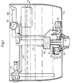
- FIGs. 1, 2 and 3 there is shown a flush cistern tank 10 fitted with a water inlet control mechanism 12.
- a water outlet fitting 14 is sealed and opened by means of a water outlet valve 16 having a seal disc 17 at its lowest extremity.
- a float 18 attached to the valve 16 provides for partial flushes, while float 20 operates a restraining force on valve 16 for complete flushes, the mode of construction and operation being fully explained in U.S. Patent No. 4,305,163.
- An inverted cup member 22 is rigidly attached to the water outlet valve 16 by means of arm 23 and positioned to be in proximity to the floor 24 of the tank 10. Co-axial with the inverted cup member 22 is a plate and stem member 26. The lower end of the stem is attached to lugs 28 extending from water outlet fitting 14, by means of a pin 30, and is restrained thereby from vertical movement. The pin 30 allows some rotational movement, this being of utility for overcoming any misalignment between the plate and the stem member 26 and the inverted cup member 22.
- the plate-and-stem member is attached to the valve 16 and the cup member 22 is attached to the water outlet fitting 14.
- the cup member 22 is assembled with its open side facing upwards
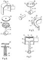
- Fig. 4 shows a further embodiment in exploded form with the cup-member being partially cut away to expose its form.
- a cup-shaped member 22 is held in inverted orientation by attachment arm 23.
- An orifice 32 is provided in the closed end of the cup 22, which orifice can be made any size needed. The larger the orifice 32, the less will be the braking effect of the shock-reduction device. The orifice diameter is easily increased and thereby there is a convenient option of speeding up valve closure at the expense of less shock attenuation. Alternatively, no orifice need be provided, the braking effect being controlled by water passing through a restricted area defined between the inner wall of the cup member and the outer surface of the plate member.
- plate stem member 26 will interchangeably also be referred to as a circular disc which is in fact the preferred configuration of the plate. This is shown, in this embodiment disc 26 as provided with a plurality of apertures 34.
- a flexible washer 36 is retained on the upper face of the disc by means of a mushroom head 38, and apertures 34 are covered by flexible washer 36.
- the lower end of the plate-and-stem member 26 is fitted with a boss 40 having a bore 42 oriented perpendicularly to the axis of the stem.
- Fig. 5 shows a preferred method of attachment of the plate and stem member 26 to the water outlet fitting 14.
- a pair of lugs 28 extend from fitting 14, each lug 20 being provided with a bore 44. The space between lugs 28 allows for the free insertion of boss 40.
- Pin 30 is inserted through bores 44 and 42, resulting in attachment of the plate-and stem member 26 to a stationary component of the cistern, member 26 retaining rotational freedom over a short arc.
- Fig. 6 illustrates a further preferred embodiment of the shock-absorbing device.
- the disc of the disc-and-stem member 26 is provided with a number of apertures 34.
- the stem of member 26 is hollow, this allowing for the free axial movement of a rod 46 joined to a cover plate 48. Fluid pressure on the outer face of plate 48 causes plate 48 to contact the disc of the disc and stem member 26; fluid pressure in the opposite direction causes plate 48 to lift and thereby allow fluid flow through apertures 34.
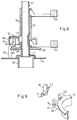
- Fig. 7 is a sectional view of a further embodiment of the shock-absorbing device.
- the inverted cup member 22 is provided with a mushroom-shaped projection 50 on the inner face at its closed end, a flexible washer 36 being thereon retained.
- the closed end of member 22 is provided with apertures 33. Fluid pressure inside volume 66 will cause washer 36 to seal apertures 33, but will allow fluid to flow in the reverse direction.
- Fig. 8 is a sectional view of an embodiment adapted to a different type of water outlet valve 52.
- the cup shaped member 22 is attached in inverted orientation to valve 52 by means of arm 23.
- a sleeve 54 hold means 20, 56 for restraining the vertical motion of valve 52.
- Sleeve 54 has a flange 58 carrying lugs 28, which lugs carry the plate-and-stem member 26 is previously explained.
- a plurality of clips 60 preferably three, serve to hold flange 58 stationary, clips 60 allowing water flow from the cistern to outlet pipe 62.
- Sleeve 54 is provided with a vertical slot which is long enough to allow free vertical movement for arm 23, and therefore of the cup shaped member 22.
- Fig. 9 is an exploded view showing a further preferred configuration for the attachment of the stem and disc member 26 to the lugs 28, which are provided with a circular bore 44, and a slot 74 whose width is less than the diameter of bore 44 and joins bore 44 to an outer edge of lug 28.
- the stem and disc member 26 is provided with projections 72 in the form of cylinders having flattened faces on planes parallel to the long axis of the stem and disc member 26. The distances between the flattened faces of the projection 72 is slightly less than the width of the slot 74, thereby making assembly of the stem 26 in between lugs 28 possible.
- the diameter of projections 72 is slightly less than the diameter of bore 44, thereby enabling the stem and disc member 26 to assume its upright operational orientation. In this preferred configuration there are no loose parts, assembly is fast and requires no tools and there is no danger of the stem and disc member 26 becoming inadvertently disengaged from lugs 28.
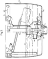
- FIG. 2 shows the components of the flush mechanism as they appear near the completion of a partial flush cycle.
- Valve 16 is in its raised open position, resulting in water outflow through water outlet fitting 14.
- Water level 64 drops rapidly, and float 18 loses the support provided by the water and consequently releases valve 16 for vertical fall.
- water is trapped in volume 66 between the cup shaped member 22 and the plate-and-stem member 26, this water providing support to tie cup-shaped member 22, thereby preventing its fast descent and as member 22 is joined to valve 16 by arm 23, also prevents the fast descent of valve 16.
- the weights of valve 16, float 18, arm 23 and cup 22 combine to pressurize water trapped in volume 66, which results in this water exiting from volume 66 through orifice 32 and around the sides of member 26.
- valve 16 While the benefits of slowing the descent velocity of valve 16 have been explained, it will be realized that on activation of the cistern's flush mechanisms, it is necessary to raise valve 16, which is affected by the user moving levers 68 or 70. There is, however, little need to reduce the upward velocity of valve 16, and it is desirable to allow for possible fast operation of levers 68 and 70. To achieve this end, it is preferable to allow the volume 66 to be increased quickly without requiring the flush mechanism to exert excessive force therefore. Figs. 4, 6 and 7 show how this is achieved by allowing substantially free passage of water into volume 66 through apertures 33 and 34. As valve 16 is raised to initiate a flush, vertical movement of cup member 22 causes an increase in volume 66, which results in reduced fluid pressure therein.
- valve 16 can be raised quickly while meeting with little resistance.
- descent of valve 16 causes a reduction in volume 66 and an increase of fluid pressure therein, this causing washer 36 to seal apertures 33 and 34.
- the trapped water must therefore leave volume 66 through the narrow passages remaining, through orifice 32 and/or around the sides of member 26.
- the resistance of the water to flow through these passages causes the cup member 22 to exert a resisting force through arm 23 to valve 16, and thereby the descent velocity of valve 16 is reduced.
- the resultant impact as valve 16 reaches its lower closed position is much reduced, thereby reducing shock, vibration, noise and excessive wear.
Landscapes
- Health & Medical Sciences (AREA)
- Life Sciences & Earth Sciences (AREA)
- Engineering & Computer Science (AREA)
- Hydrology & Water Resources (AREA)
- Public Health (AREA)
- Water Supply & Treatment (AREA)
- Self-Closing Valves And Venting Or Aerating Valves (AREA)
Abstract
A shock-damping device for flush valve mechanisms of the type having a water outlet valve (16) liftable off the water outlet (14) of a flush cistern (10) comprises a cup shaped member (22) and a body member (26) configured to freely move within the inner surface of the cup, the cup shaped member and the body member defining therebetween a changeable volume (66) of substantially surrounded space and having or defining restricted openings (32) for the passage of water into and out of the space, one of the members (22) being provided with means (23) for attachment to the water outlet valve (16) whereby any vertical movement of the water outlet valve will also be effected by the member, and the remaining member (26) being provided with means (28) for attachment to a stationary component of the cistern, and being located so that the body member may reciprocate inside the cup shaped member, whereby descent velocity of the valve (16) at the completion of a partial flush is reduced by the resistance of the water forced through the restricted openings (32) as a result of the descent of the valve attached member (22) toward the cistern attached member (26).
Description
- The present invention relates to a flush valve mechanism for the water outlet of a flush cistern and to improved flush cisterns provided therewith.
- More particularly, the present invention relates to a quiet and long-lasting flush valve mechanism for releasing and discharging water from a flush cistern into a toilet bowl, and is adapted for use in selective flushing mechanisms which provide for partial as well as complete flushes such as that described in U.S. Patent 4,305,163, the teachings of which are incorporated herein by reference.
- The need to preserve water resources and to avoid wastage is now accepted not only in semi-arid regions but also in areas blessed with adequate rainfall. Much effort has gone into the development of means for saving water, and as part of these efforts, the flush-cistern toilet has been much improved to reduce wastage, as is evidenced by such U.S. patents as 3,955 218, 4,171,547 and many others. In particular, the development of dual-volume flush systems has made a very substantial contribution to saving huge quantities of fresh water.
- There is, however, one requirement for a flush-cistern toilet which has not yet been addressed by devices of prior art - and this is that quiet operation should be achieved. While in noisy locations such as factories and airports, some extra noise is not objectionable, excess noise, particularly that emanating from toilets, must be avoided in hotels, most offices and homes. In fact, many homemakers will be deterred from installing an improved water saving flush system if the price to be paid includes excessive noise by day and night. Referring now in particular to the dual-volume flush systems of the type having a water outlet valve liftable off the water outlet of the flush cistern and provided with means for selectively restraining and releasing said water outlet valve to selectively allow both partial and complete flushes. The noise of highest volume is emitted as a result of the free fall of the water outlet valve at the completion of the flushing action. This outlet valve which has affixed at its lower extremity a flexible seal disc, falls until impacting the water outlet, the resultant shock causing vibration and noise. A further undesirable by-product of this impact is accelerated wear of various parts, and in particular, of the flexible seal disc.
- The problem of impact is particularly acute in the case of dual-volume flush cisterns. Two factors have been identified which explain why this problem is more severe during a partial volume flush. They are:
- (a) During a partial volume flush the lower part of the cistern continues to hold water during the downward movement of the outlet valve assembly. The resultant water pressure on the upper surface of the sealing disk applies a downward force on this disc, this force not being completely balanced at the underside of said disc, which is in a low-pressure area resulting from water flow through the cistern outlet.
- (b) The dynamic effect of the fluid flow near the cistern outlet applies an additional force on the lower extremity of the outlet valve and in particular, on the seal disc. While at the completion of a full volume flush, air can enter a vertical tube water outlet valve, and separate the seal disc from the fast-flowing water, this is not so during a partial-volume flush, and the seal disc is subjected to the forces resulting from entrainment of the seal disc on the fast flowing water.
- In accordance with the present invention, there is now provided a simple and inexpensive addition of a shock reduction mechanism, particularly useful for dual-volume flush cisterns of the type exemplified by U.S. Patent 4,305,163. However, it is noted that the present invention can also be applied to similar types of flushing mechanisms which suffer from the same problem heretofore described and including mechanisms of the type offering only full-volume flushes. This proposed simple mechanism reduces impact shock to a negligible level for partial flushes, thereby eliminating the loudest sound of the flushing action and additionally extending the useful life of the mechanism components, and also allowing for maximum utilization of the full amount of water in the cistern for full flushes thus ameliorating the problem of residual water left in the cistern after a flushing action.
- Accordingly, the present invention provides a shock-damping device for flush valve mechanisms of the type having a water outlet valve liftable off the water outlet of a flush cistern, said device comprising a cup shaped member and a body member, said body member being configured to freely move within the inner surface of said cup, said cup shaped member and said body member defining therebetween a changeable volume of substantially surrounded space and having or defining restricted openings for the passage of water into and out of said space, one of said members being provided with means for attachment to said water outlet valve whereby upon attachment of said member to said valve, any vertical movement of the water outlet valve will also be affected by said member, and the remaining member being provided with means for attachment to a stationary component of said cistern, and being located so that said body member may reciprocate inside said cup shaped member, whereby descent velocity of said valve at the completion of a flush is reduced by the resistance of the water forced through said restricted openings as a result of the descent of said valve attached member towards said cistern attached member.
- The invention also provides a water outlet valve liftable off the water outlet of a flush cistern in combination with a shock damping device as defined hereinbefore, and being connected to one member thereof, the remaining member of said shock damping device being provided with means for attachment to a stationary component of said cistern and in proximity to the bottom of said cistern.
- The body member of the shock-damping device of the present invention can be of any suitable configuration and thus could be in the form of a cylindrical body, a spherical body with a depending stem, a helical screw as well as other geometrical and non-geometrical shapes. Preferably, said member will be a simple plate with a depending stem.
- Said plate member may also be of any suitable configuration such as circular, hexagonal, square, etc. provided that the cross-section of the cup is of similar configuration to provide for close proximity between the edge of the plate and inner surface of the cup. As stated the remaining member is provided with means for attachment to a stationary component of the cistern which stationary component can be a side wall of the cistern, the cistern floor or preferably to the water outlet fitting of the cistern.
- The invention will now be described in connection with certain preferred embodiments with reference to the following illustrative figures so that it may be more fully understood.
- With specific reference now to the figures in detail, it is stressed that the particulars shown are by way of example and for purposes of illustrative discussion of the preferred embodiments of the present invention only and are presented in the cause of providing what is believed to be the most useful and readily understood description of the principles and conceptual aspects of the invention. In this regard, no attempt is made to show structural details of the invention in more detail than is necessary for a fundamental understanding of the invention, the description taken with the drawings making apparent to those skilled in the art how the several forms of the invention may be embodied in practice.
- In the drawings:
- Fig. 1
- is a sectional view of one embodiment of the shock absorbing device, as assembled to a water outlet valve in a flush cistern shown with the cistern full.
- Fig. 2
- shows the same components as Fig. 1, near the completion of a partial flush.
- Fig. 3
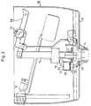
- also shows the same components as Fig. 1, near the completion of a full flush.
- Fig. 4
- is an isometric exploded view of a second embodiment of the invention.
- Fig. 5
- is an isometric exploded view showing attachment of the stem and disc member.
- Fig. 6
- is a sectional view of a further embodiment.
- Fig. 7
- is a sectional view of a yet further embodiment.
- Fig. 8
- is a sectional view of an embodiment adapted to a different type of flush mechanism, and
- Fig. 9
- is an isometric exploded view showing a preferred configuration of the stem and disc member and its attachment lug.
- With reference to Figs. 1, 2 and 3, there is shown a
flush cistern tank 10 fitted with a waterinlet control mechanism 12. A water outlet fitting 14 is sealed and opened by means of awater outlet valve 16 having aseal disc 17 at its lowest extremity. Afloat 18 attached to thevalve 16 provides for partial flushes, whilefloat 20 operates a restraining force onvalve 16 for complete flushes, the mode of construction and operation being fully explained in U.S. Patent No. 4,305,163. - An inverted
cup member 22 is rigidly attached to thewater outlet valve 16 by means ofarm 23 and positioned to be in proximity to thefloor 24 of thetank 10. Co-axial with the invertedcup member 22 is a plate andstem member 26. The lower end of the stem is attached tolugs 28 extending from water outlet fitting 14, by means of apin 30, and is restrained thereby from vertical movement. Thepin 30 allows some rotational movement, this being of utility for overcoming any misalignment between the plate and thestem member 26 and the invertedcup member 22. - In a further embodiment of the invention (not shown) the plate-and-stem member is attached to the
valve 16 and thecup member 22 is attached to the water outlet fitting 14. In this embodiment thecup member 22 is assembled with its open side facing upwards - Fig. 4 shows a further embodiment in exploded form with the cup-member being partially cut away to expose its form. A cup-
shaped member 22 is held in inverted orientation byattachment arm 23. Anorifice 32 is provided in the closed end of thecup 22, which orifice can be made any size needed. The larger theorifice 32, the less will be the braking effect of the shock-reduction device. The orifice diameter is easily increased and thereby there is a convenient option of speeding up valve closure at the expense of less shock attenuation. Alternatively, no orifice need be provided, the braking efect being controlled by water passing through a restricted area defined between the inner wall of the cup member and the outer surface of the plate member. - In this embodiment and in the discussion hereinafter, plate stem
member 26 will interchangeably also be referred to as a circular disc which is in fact the preferred configuration of the plate. This is shown, in thisembodiment disc 26 as provided with a plurality ofapertures 34. - A
flexible washer 36 is retained on the upper face of the disc by means of amushroom head 38, andapertures 34 are covered byflexible washer 36. The lower end of the plate-and-stem member 26 is fitted with aboss 40 having abore 42 oriented perpendicularly to the axis of the stem. - Fig. 5 shows a preferred method of attachment of the plate and stem
member 26 to the water outlet fitting 14. A pair oflugs 28 extend from fitting 14, eachlug 20 being provided with abore 44. The space betweenlugs 28 allows for the free insertion ofboss 40.Pin 30 is inserted throughbores stem member 26 to a stationary component of the cistern,member 26 retaining rotational freedom over a short arc. - Fig. 6 illustrates a further preferred embodiment of the shock-absorbing device. The disc of the disc-and-
stem member 26 is provided with a number ofapertures 34. The stem ofmember 26 is hollow, this allowing for the free axial movement of arod 46 joined to acover plate 48. Fluid pressure on the outer face ofplate 48 causesplate 48 to contact the disc of the disc and stemmember 26; fluid pressure in the opposite direction causesplate 48 to lift and thereby allow fluid flow throughapertures 34. - Fig. 7 is a sectional view of a further embodiment of the shock-absorbing device. The
inverted cup member 22 is provided with a mushroom-shapedprojection 50 on the inner face at its closed end, aflexible washer 36 being thereon retained. The closed end ofmember 22 is provided withapertures 33. Fluid pressure insidevolume 66 will causewasher 36 to sealapertures 33, but will allow fluid to flow in the reverse direction. - Fig. 8 is a sectional view of an embodiment adapted to a different type of
water outlet valve 52. The cup shapedmember 22 is attached in inverted orientation tovalve 52 by means ofarm 23. Asleeve 54 hold means 20, 56 for restraining the vertical motion ofvalve 52.Sleeve 54 has aflange 58 carrying lugs 28, which lugs carry the plate-and-stem member 26 is previously explained. A plurality ofclips 60, preferably three, serve to holdflange 58 stationary, clips 60 allowing water flow from the cistern tooutlet pipe 62.Sleeve 54 is provided with a vertical slot which is long enough to allow free vertical movement forarm 23, and therefore of the cup shapedmember 22. - Fig. 9 is an exploded view showing a further preferred configuration for the attachment of the stem and
disc member 26 to thelugs 28, which are provided with acircular bore 44, and aslot 74 whose width is less than the diameter ofbore 44 and joins bore 44 to an outer edge oflug 28. The stem anddisc member 26 is provided withprojections 72 in the form of cylinders having flattened faces on planes parallel to the long axis of the stem anddisc member 26. The distances between the flattened faces of theprojection 72 is slightly less than the width of theslot 74, thereby making assembly of thestem 26 in betweenlugs 28 possible. The diameter ofprojections 72 is slightly less than the diameter ofbore 44, thereby enabling the stem anddisc member 26 to assume its upright operational orientation. In this preferred configuration there are no loose parts, assembly is fast and requires no tools and there is no danger of the stem anddisc member 26 becoming inadvertently disengaged fromlugs 28. - Operation of the device can best be explained in reference to Fig. 2, which shows the components of the flush mechanism as they appear near the completion of a partial flush cycle.
Valve 16 is in its raised open position, resulting in water outflow through water outlet fitting 14.Water level 64 drops rapidly, and float 18 loses the support provided by the water and consequently releasesvalve 16 for vertical fall. However, water is trapped involume 66 between the cup shapedmember 22 and the plate-and-stem member 26, this water providing support to tie cup-shapedmember 22, thereby preventing its fast descent and asmember 22 is joined tovalve 16 byarm 23, also prevents the fast descent ofvalve 16. The weights ofvalve 16,float 18,arm 23 andcup 22 combine to pressurize water trapped involume 66, which results in this water exiting fromvolume 66 throughorifice 32 and around the sides ofmember 26. - While the benefits of slowing the descent velocity of
valve 16 have been explained, it will be realized that on activation of the cistern's flush mechanisms, it is necessary to raisevalve 16, which is affected by theuser moving levers valve 16, and it is desirable to allow for possible fast operation oflevers volume 66 to be increased quickly without requiring the flush mechanism to exert excessive force therefore. Figs. 4, 6 and 7 show how this is achieved by allowing substantially free passage of water intovolume 66 throughapertures valve 16 is raised to initiate a flush, vertical movement ofcup member 22 causes an increase involume 66, which results in reduced fluid pressure therein. Thereafter water entersvolume 66 throughapertures flexible washer 36 on entry. The effect of the foregoing is thatvalve 16 can be raised quickly while meeting with little resistance. However, descent ofvalve 16 causes a reduction involume 66 and an increase of fluid pressure therein, this causingwasher 36 to sealapertures volume 66 through the narrow passages remaining, throughorifice 32 and/or around the sides ofmember 26. The resistance of the water to flow through these passages causes thecup member 22 to exert a resisting force througharm 23 tovalve 16, and thereby the descent velocity ofvalve 16 is reduced. The resultant impact asvalve 16 reaches its lower closed position is much reduced, thereby reducing shock, vibration, noise and excessive wear. - It will be evident to those skilled in the art that the invention is not limited to the details of the foregoing illustrative examples and that the present invention may be emobodied in other specific forms without departing from the essential attributes thereof, and it is therefore desired that the present embodiments and examples be considered in all respects as illustrative and not restrictive, reference being made to the appended claims, rather than to the foregoing description, and all changes which come within the meaning and range of equivalency of the claims are therefore intended to be embraced therein.
Claims (9)
- A shock-damping device for flush valve mechanisms of the type having a water outlet valve liftable off the water outlet of a flush cistern, said device comprising a cup shaped member and a body member, said body member being configured to freely move within the inner surface of said cup, said cup shaped member and said body member defining therebetween a changeable volume of substantially surrounded space and having or defining restricted openings for the passage of water into and out of said space, one of said members being provided with means for attachment to said water outlet valve whereby upon attachment of said member to said valve, any vertical movement of the water outlet valve will also be affected by said member, and the remaining member being provided with means for attachment to a stationary component of said cistern, and being located so that said body member may reciprocate inside said cup shaped member, whereby descent velocity of said valve at the completion of a partial flush is reduced by the resistance of the water forced through said restricted openings as a result of the descent of said valve attached member towards said cistern attached member.
- A shock-damping device as claimed in Claim 1 wherein said body member is a plate-and-stem member.
- A shock-damping device as claimed in Claim 2, wherein the plate of said plate-and-stem member is provided with at least one aperture, and wherein a flexible washer is partially attached to a face of said plate opposite the stem, whereby said flexible washer will allow passage of a fluid flowing from the direction of the stem but will seal the aperture before a fluid pressurized to flow in the reverse direction.
- A shock-damping device as claimed in Claim 2, wherein the plate of said plate-and-stem member is provided with at least one aperture, and further being provided with a cover plate axially mounted to afford reciprocal movement on top of said plate and stem member, said cover plate sealing said aperture when in contact with said plate and allowing substantially free passage for a fluid when in spaced relationship to same.
- A shock-damping device as claimed in Claim 1, wherein the closed end of said cup shaped member is provided with an orifice.
- A shock-damping device as claimed in Claim 5, further being provided with a flexible washer partially attached inside the cup shaped member to the end wall of the cup, whereby said flexible washer will allow passage of a fluid flowing through the orifice into said cup-shaped member, but will seal the orifice before a fluid pressurized to flow in the reverse direction.
- A shock-damping device as claimed in Claim 2, wherein the stem of said plate and stem member has at the extremity furthest from the plate attachment means which allow at least partial rotation of the stem on an axis perpendicular to the axis of the stem.
- A water outlet valve liftable off the water outlet of a flush cistern in combination with a shock damping device as claimed in Claim 1, and being connected to one member thereof, the remaining member of said shock damping device being provided with means for attachment to a stationary component of said cistern in proximity to the bottom of said cistern.
- A water outlet valve as claimed in Claim 8 wherein the cup shaped member of the shock-damping device is connected to the water outlet valve and the body member is provided with means for attachment to a stationary component of said cistern.
Priority Applications (1)
| Application Number | Priority Date | Filing Date | Title |
|---|---|---|---|
| EP91302079A EP0503177A1 (en) | 1991-03-12 | 1991-03-12 | Shock damping device for flush valve mechanism |
Applications Claiming Priority (1)
| Application Number | Priority Date | Filing Date | Title |
|---|---|---|---|
| EP91302079A EP0503177A1 (en) | 1991-03-12 | 1991-03-12 | Shock damping device for flush valve mechanism |
Publications (1)
| Publication Number | Publication Date |
|---|---|
| EP0503177A1 true EP0503177A1 (en) | 1992-09-16 |
Family
ID=8208216
Family Applications (1)
| Application Number | Title | Priority Date | Filing Date |
|---|---|---|---|
| EP91302079A Ceased EP0503177A1 (en) | 1991-03-12 | 1991-03-12 | Shock damping device for flush valve mechanism |
Country Status (1)
| Country | Link |
|---|---|
| EP (1) | EP0503177A1 (en) |
Cited By (3)
| Publication number | Priority date | Publication date | Assignee | Title |
|---|---|---|---|---|
| EP1024230A2 (en) | 1999-01-27 | 2000-08-02 | Friatec Aktiengesellschaft | Device for activating the outlet valve of a flushing tank |
| DE19914841A1 (en) * | 1999-01-27 | 2000-08-24 | Friatec Ag | Device for actuating the valve of a cistern |
| EP2505727A1 (en) * | 2011-03-30 | 2012-10-03 | Geberit International AG | Drain valve for a cistern |
Citations (5)
| Publication number | Priority date | Publication date | Assignee | Title |
|---|---|---|---|---|
| US2879521A (en) * | 1957-12-23 | 1959-03-31 | James H Brasher | Attachment for flush tanks |
| US4101986A (en) * | 1977-07-29 | 1978-07-25 | Ng Walter C | Regulatable flush valve for tank flush toilets |
| FR2442306A1 (en) * | 1978-11-22 | 1980-06-20 | Renard Michel | Variable flush toilet cistern - has valve arranged such that discharge is proportional to length of pull on operating handle |
| US4587679A (en) * | 1984-12-05 | 1986-05-13 | Chen Chin Lin | Toilet flushing device |
| FR2601401A1 (en) * | 1986-07-10 | 1988-01-15 | Axinove | Double action flush cistern - has valve and bellows sleeve which release different amounts of water when lever raises or depresses control rod |
-
1991
- 1991-03-12 EP EP91302079A patent/EP0503177A1/en not_active Ceased
Patent Citations (5)
| Publication number | Priority date | Publication date | Assignee | Title |
|---|---|---|---|---|
| US2879521A (en) * | 1957-12-23 | 1959-03-31 | James H Brasher | Attachment for flush tanks |
| US4101986A (en) * | 1977-07-29 | 1978-07-25 | Ng Walter C | Regulatable flush valve for tank flush toilets |
| FR2442306A1 (en) * | 1978-11-22 | 1980-06-20 | Renard Michel | Variable flush toilet cistern - has valve arranged such that discharge is proportional to length of pull on operating handle |
| US4587679A (en) * | 1984-12-05 | 1986-05-13 | Chen Chin Lin | Toilet flushing device |
| FR2601401A1 (en) * | 1986-07-10 | 1988-01-15 | Axinove | Double action flush cistern - has valve and bellows sleeve which release different amounts of water when lever raises or depresses control rod |
Cited By (3)
| Publication number | Priority date | Publication date | Assignee | Title |
|---|---|---|---|---|
| EP1024230A2 (en) | 1999-01-27 | 2000-08-02 | Friatec Aktiengesellschaft | Device for activating the outlet valve of a flushing tank |
| DE19914841A1 (en) * | 1999-01-27 | 2000-08-24 | Friatec Ag | Device for actuating the valve of a cistern |
| EP2505727A1 (en) * | 2011-03-30 | 2012-10-03 | Geberit International AG | Drain valve for a cistern |
Similar Documents
| Publication | Publication Date | Title |
|---|---|---|
| US6679285B2 (en) | Faucet for filling tanks | |
| CA2627917C (en) | Canister flush valve | |
| US4651359A (en) | Dual mode flush valve assembly | |
| US4183108A (en) | Flush toilet system | |
| US5396665A (en) | Shock damping device for flush valve mechanism | |
| PL179725B1 (en) | Outflow valve | |
| KR20050035898A (en) | High performance flush valve assembly | |
| JP3441806B2 (en) | Hydraulic valve and flow control method | |
| US5524297A (en) | Two-level flush valve | |
| EP0503177A1 (en) | Shock damping device for flush valve mechanism | |
| US4138749A (en) | Two-stage hydraulic flush control device | |
| US4135262A (en) | Dual flush devices for toilets | |
| WO1979000780A1 (en) | Water closet | |
| US4066187A (en) | Valve unit for liquid dispensers | |
| US5375268A (en) | Ballfloat toilet flush control system | |
| KR100456786B1 (en) | Hinge for Auto-Closing Door | |
| CA2247631C (en) | Flush valve refill ring | |
| US5004462A (en) | Adjustable water-level flushing apparatus | |
| US4587679A (en) | Toilet flushing device | |
| US4709721A (en) | Integral base refill system ballcock assembly | |
| US5465432A (en) | Device to secure toilet flush lever arm to effect a partial flush | |
| AU685963B2 (en) | Improvements in inlet flow valves | |
| US4134164A (en) | Water standpipe for toilet sump tanks | |
| US3911504A (en) | Toilet flush tank apparatus | |
| WO2022006093A1 (en) | Flush valve apparatus |
Legal Events
| Date | Code | Title | Description |
|---|---|---|---|
| PUAI | Public reference made under article 153(3) epc to a published international application that has entered the european phase |
Free format text: ORIGINAL CODE: 0009012 |
|
| AK | Designated contracting states |
Kind code of ref document: A1 Designated state(s): AT BE CH DE DK ES FR GB GR IT LI LU NL SE |
|
| 17P | Request for examination filed |
Effective date: 19930305 |
|
| 17Q | First examination report despatched |
Effective date: 19940909 |
|
| STAA | Information on the status of an ep patent application or granted ep patent |
Free format text: STATUS: THE APPLICATION HAS BEEN REFUSED |
|
| 18R | Application refused |
Effective date: 19951020 |