EP1666831A1 - Halter zur Halterung eines Zahnmodells zur Herstellung von Rotationsaufnahmen sowie Haltevorrichtung - Google Patents
Halter zur Halterung eines Zahnmodells zur Herstellung von Rotationsaufnahmen sowie Haltevorrichtung Download PDFInfo
- Publication number
- EP1666831A1 EP1666831A1 EP05110668A EP05110668A EP1666831A1 EP 1666831 A1 EP1666831 A1 EP 1666831A1 EP 05110668 A EP05110668 A EP 05110668A EP 05110668 A EP05110668 A EP 05110668A EP 1666831 A1 EP1666831 A1 EP 1666831A1
- Authority
- EP
- European Patent Office
- Prior art keywords
- holder
- cone
- mandrel
- shaft
- holding device
- Prior art date
- Legal status (The legal status is an assumption and is not a legal conclusion. Google has not performed a legal analysis and makes no representation as to the accuracy of the status listed.)
- Granted
Links
- 230000008878 coupling Effects 0.000 claims abstract description 8
- 238000010168 coupling process Methods 0.000 claims abstract description 8
- 238000005859 coupling reaction Methods 0.000 claims abstract description 8
- 241000047428 Halter Species 0.000 description 5
- 238000005259 measurement Methods 0.000 description 3
- 230000015572 biosynthetic process Effects 0.000 description 1
- 239000013013 elastic material Substances 0.000 description 1
- 210000003746 feather Anatomy 0.000 description 1
- 230000013011 mating Effects 0.000 description 1
- 238000000034 method Methods 0.000 description 1
- 230000007704 transition Effects 0.000 description 1
Images


Classifications
-
- A—HUMAN NECESSITIES
- A61—MEDICAL OR VETERINARY SCIENCE; HYGIENE
- A61C—DENTISTRY; APPARATUS OR METHODS FOR ORAL OR DENTAL HYGIENE
- A61C13/00—Dental prostheses; Making same
- A61C13/12—Tools for fastening artificial teeth; Holders, clamps, or stands for artificial teeth
-
- A—HUMAN NECESSITIES
- A61—MEDICAL OR VETERINARY SCIENCE; HYGIENE
- A61C—DENTISTRY; APPARATUS OR METHODS FOR ORAL OR DENTAL HYGIENE
- A61C13/00—Dental prostheses; Making same
- A61C13/0003—Making bridge-work, inlays, implants or the like
- A61C13/0004—Computer-assisted sizing or machining of dental prostheses
Definitions
- the invention relates to a holder for a tooth model for measuring the tooth model, which includes a receiving part for the model and a shaft connected to the receiving part for mounting in a holder of a surveying device, wherein the shaft has a coupling part comprising a cone. Furthermore, the invention relates to a holding device for a holder of the aforementioned type, which has a mandrel for attaching the holder, wherein the mandrel is designed as a counter-cone.
- holders are known in the prior art, which can be rotatably mounted with respect to the image pickup unit.
- the company etkon AG sells surveying equipment which has fixedly mounted in the device holder which are rotatable relative to the image pickup unit.
- the holders have a plasticine in which the tooth models to be measured are fastened.
- the disadvantage here is the rigid attachment of the holder in the device.
- potty holder known by means of a screwed Clamping device can be rotatably mounted on a holding device. The assembly and disassembly of such a holder requires increased effort.
- the holder according to the invention for a dental model for measuring the tooth model includes a receiving part for the dental model and a connected to the receiving part shaft for mounting in a holder of a surveying device wherein the shaft has a coupling part comprising a cone.
- the holder can be plugged with the cone on a correspondingly shaped holder of a surveying device, wherein the holder is fixed by the predetermined geometry of the cone both axially and radially in the intended direction and beyond there is a very good adhesion between the holder and the holder ,
- the cone is formed as an inner cone, which is arranged on the receiving part remote from the end of the shaft.
- the formation of the cone as an inner cone on the one hand has the advantage that the corresponding opposite can be designed as an outer cone and accumulates in this spatially upwardly arranged counterpart no dirt.
- the receiving part, the shaft and the coupling part are rotationally symmetrical. Then there is no preferred direction with respect to the attachment of the dental model on the holder and the holder can be mounted in any orientation in the holder of the surveying device.
- the receiving part for the tooth model, the shaft and the coupling part substantially the same axis of rotation. This ensures a radially stationary positioning of the tooth model to be measured during rotation.
- the cone has an angle between two and nine degrees. Too large a cone angle causes a poor power connection and too small an angle a bad centering.
- a centering section is located on the inner cone.
- Such a centering section can be formed, for example, by a cylindrical cavity adjoining the conical area. This can be achieved even better centering of the holder on the holder.
- the shaft is designed to be elastic in the region of the cone. Then it is possible to improve the frictional engagement between the holder and the holder.
- the elasticity can also be achieved by a slot in the shaft in the region of the cone.
- the receiving part for the dental model is designed as a potty.
- a holder allows a variety of different mounting options.
- the potty contains a moldable mass in which the tooth model can be fastened. So it is possible to attach a tooth model to be measured detachably and yet sufficiently safe for the measurement in the holder and to correct a positioning, if necessary by hand.
- the holding device has a mandrel for attaching the holder, wherein the mandrel is designed as a counter-cone to the cone of the holder, in particular as an outer cone.
- a holding device allows a very simple, secure and accurate attachment of the holder.
- the mandrel is resiliently mounted, wherein the spring travel of the mandrel is limited by a stop.
- a stop When placing the holder on the mandrel this gives, depending on the force with which the holder is placed on, and touched when reaching the intended Aufsteckkraft the stop.
- the placement is made in the sequence always with the same constant force, whereby the holder is always positioned in the same position.
- the angle of the cone of the mandrel is as large as the angle of the cone of the holder, wherein a tolerance of less than or equal to 1 degree is possible. This ensures a secure fit of the holder on the mandrel with the largest possible friction surface.
- the mandrel is equipped with a centering pin, which is arranged adjacent to the cone. Then it is possible to allow an even more accurate positioning of the holder.
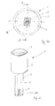
- FIG. 1A shows a holder 1 for a dental model 2, which has a cylindrical, cup-shaped part 3 with a shaft 4 attached thereto.
- the tooth model 2 can also be a prepared stump (shown in dashed lines).
- the shaft is made of an elastic material capable of yielding slightly under tensile loads.
- the potty 3 is filled with a mouldable mass 5, for example a putty, for fixing and positioning the tooth replacement part 2.
- an inner cone 6 is provided, which has an opening angle ⁇ of 12 degrees for clarity.
- Behind the cone-shaped end of the shaft designed as a hollow shaft portion centering portion 7 is provided to provide space for a mandrel and to improve the elasticity of the shaft 4.
- the potty 3, the shaft 4, the cone 6 and the centering 7 are arranged rotationally symmetrical to the axis of rotation R.
- Fig. 1B shows the holder 1 in a plan view.
- the potty 3 is cylindrical, with the cylinder axis simultaneously represents the rotation axis R.
- the tooth model 2 to be measured is embedded in the plasticine 5 in such a way that the center of the object of the dental model 2 coincides approximately with the axis of rotation R.
- a holder 1 ' is shown in an alternative embodiment.
- the shaft 4 has here for generating a flexibility on a slot 22 which extends in the region of the cone 6.
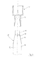
- Fig. 3 shows a holding device 21 according to the invention, consists of a holder 1 and a mandrel 8, which is resiliently mounted by means of a spring 9.
- the mandrel 8 is divided into a conical region 10 and a cylindrical region 11.
- the tip 12 of the conical region has a diameter d D and is smaller than the diameter d S of the centering section 7 of the shaft 4.
- the mandrel 15 has in this case three areas.
- the cylindrical region 16 is adjoined by a conical region 17, on the front surface 18 of which a centering pin 19 is attached.
- the centering pin 19 is cylindrical and has substantially the same diameter as the diameter d s centering portion 7 of the shaft 4.
- the transition between the conical region 17 and the centering pin 19 is provided with a step, which ensures that when pushing together of the holder 1 and the mandrel 15 is no incorrect positioning due to the otherwise required completely flush contact the mating surfaces.
- Fig. 5 shows the holder 1 is pushed onto the mandrel 15. Between the centering pin 19, the conical portion 17 and the conical portion 6 of the shaft 4 is formed by the stepped diameter, a cavity 20 in which no contact between the holder 1 and the Thorn 15 exists.
Landscapes
- Health & Medical Sciences (AREA)
- General Health & Medical Sciences (AREA)
- Veterinary Medicine (AREA)
- Epidemiology (AREA)
- Life Sciences & Earth Sciences (AREA)
- Animal Behavior & Ethology (AREA)
- Oral & Maxillofacial Surgery (AREA)
- Public Health (AREA)
- Dentistry (AREA)
- Dental Tools And Instruments Or Auxiliary Dental Instruments (AREA)
- Machine Tool Copy Controls (AREA)
- Toys (AREA)
- Pressure Welding/Diffusion-Bonding (AREA)
- Dental Prosthetics (AREA)
- Clamps And Clips (AREA)
Abstract
Description
- Die Erfindung betrifft einen Halter für ein Zahnmodell zur Vermessung des Zahnmodells, das ein Aufnahmeteil für das Modell sowie einen mit dem Aufnahmeteil verbundenen Schaft zur Befestigung in einer Halterung einer Vermessungseinrichtung beinhaltet, wobei der Schaft ein Kupplungsteil aufweist, das einen Konus umfasst. Weiterhin betrifft die Erfindung eine Haltevorrichtung für einen Halter oben genannter Art, die einen Dorn zum Aufstecken des Halters aufweist, wobei der Dorn als Gegenkonus ausgebildet ist.
- Es sind im Stand der Technik Halter für Zahnmodelle bekannt, die bei der Vermessung der Zahnmodelle verwendet werden. Abhängig von der Art der Vermessung sowie der Größe der zu vermessenden Zahnmodelle gibt es Halter, die für die Halterung eines Einzelzahnmodells gedacht sind und solche, die einen ganzen Kieferabdruck halten können.
- Oftmals ist es erwünscht, ein Einzelzahnmodell von mehreren Seiten gleichzeitig zu vermessen. Dafür sind im Stand der Technik Halter bekannt, die drehbar bezüglich der Bildaufnahmeeinheit befestigt werden können. Die Firma etkon AG vertreibt Vermessungseinrichtungen, die fest in das Gerät eingebaute Halter aufweisen, die bezüglich der Bildaufnahmeeinheit drehbar sind. Die Halter weisen eine Knetmasse auf, in der die zu vermessenden Zahnmodelle befestigt werden. Nachteilig ist hier die starre Befestigung der Halter im Gerät. Darüber hinaus sind von der Firma Sirona Dental Systems GmbH Töpfchenhalter bekannt, die mittels einer geschraubten Klemmvorrichtung drehbar auf einer Haltevorrichtung befestigt werden können. Die Montage und Demontage eines solchen Halters erfordert erhöhten Aufwand.
- Es ist daher die Aufgabe der Erfindung, einen Halter für ein Zahnmodell anzugeben, der eine einfache, sichere und genaue Befestigung und Positionierung des Halters in der Vermessungseinrichtung ermöglicht und der schmutzempfindlich ist und niedrige Herstellungskosten verursacht.
- Diese Aufgabe wird erfindungsgemäß gelöst durch einen Halter gemäß dem Anspruch 1 sowie einer Haltevorrichtung gemäß dem Anspruch 10. Der erfindungsgemäße Halter für ein Zahnmodell zur Vermessung des Zahnmodells enthält ein Aufnahmeteil für das Zahnmodell sowie einen mit dem Aufnahmeteil verbundenen Schaft zur Befestigung in eine Halterung einer Vermessungseinrichtung, wobei der Schaft ein Kupplungsteil aufweist, das einen Konus umfasst. Der Halter kann mit dem Konus auf eine entsprechend gestaltete Halterung einer Vermessungseinrichtung aufgesteckt werden, wobei der Halter durch die vom Konus vorgegebene Geometrie sowohl axial als auch radial in der vorgesehenen Richtung fixiert wird und darüber hinaus ein sehr guter Kraftschluss zwischen der Halterung und dem Halter besteht.
- Vorteilhafterweise ist der Konus als Innenkonus ausgebildet, der an dem Aufnahmeteil abgewandten Ende des Schaftes angeordnet ist. Die Ausbildung des Konus als Innenkonus hat einerseits den Vorteil, dass das entsprechende Gegenteil als Außenkonus gestaltet werden kann und sich in diesem, räumlich nach oben angeordneten Gegenstück kein Schmutz ansammelt.
- Vorteilhafterweise sind das Aufnahmeteil, der Schaft und das Kupplungsteil rotationssymmetrisch gestaltet. Dann besteht bezüglich der Befestigung des Zahnmodells auf dem Halter keine Vorzugsrichtung und der Halter kann in beliebiger Orientierung in der Halterung der Vermessungseinrichtung befestigt werden.
- Vorteilhafterweise weisen das Aufnahmeteil für das Zahnmodell, der Schaft und das Kupplungsteil im Wesentlichen dieselbe Rotationsachse auf. Dies gewährleistet eine radial ortsfeste Positionierung des zu vermessenden Zahnmodells bei der Rotation.
- Vorteilhafterweise hat der Konus einen Winkel zwischen zwei und neun Grad. Ein zu großer Konuswinkel bewirkt einen schlechten Kraftanschluss und ein zu kleiner Winkel eine schlechte Zentrierung.
- Vorteilhafterweise befindet sich an dem Innenkonus ein Zentrierabschnitt. Ein solcher Zentrierabschnitt kann beispielsweise durch einen sich an den konischen Bereich anschließenden zylindrischen Hohlraum gebildet werden. Damit kann eine noch bessere Zentrierung des Halters auf der Halterung erreicht werden.
- Vorteilhafterweise ist der Schaft im Bereich des Konus elastisch ausgebildet. Dann ist es möglich, den Reibschluss zwischen Halter und Halterung zu verbessern.
- Die Elastizität kann auch durch einen Schlitz im Schaft im Bereich des Konus erreicht werden.
- Vorteilhafterweise ist das Aufnahmeteil für das Zahnmodell als Töpfchen gestaltet. Ein solcher Halter erlaubt eine Vielzahl von unterschiedlichen Befestigungsmöglichkeiten.
- Vorteilhafterweise enthält das Töpfchen eine formbare Masse, in der das Zahnmodell befestigbar ist. So ist es möglich, ein zu vermessendes Zahnmodell lösbar und doch ausreichend sicher für die Vermessung in dem Halter zu befestigen und eine Positionierung gegebenenfalls per Hand zu korrigieren.
- Ein weiterer Gegenstand der Erfindung betrifft eine Haltevorrichtung für einen Halter, wie er zuvor offenbart wurde. Die Haltevorrichtung weist einen Dorn zum Aufstecken des Halters auf, wobei der Dorn als Gegenkonus zum Konus des Halters ausgebildet ist, insbesondere als Außenkonus. Eine solche Haltevorrichtung ermöglicht eine sehr einfache, sichere und exakte Befestigung des Halters.
- Vorteilhafterweise ist der Dorn federnd gelagert, wobei der Federweg des Dorns durch einen Anschlag begrenzt ist. Beim Aufsetzen des Halters auf den Dorn gibt dieser, abhängig von der Kraft, mit der der Halter aufgesetzt wird, nach und berührt bei Erreichen der vorgesehenen Aufsteckkraft den Anschlag. Das Aufsetzen wird in der Folge immer mit derselben konstanten Kraft vorgenommen, wodurch der Halter immer in der gleichen Lage positioniert wird.
- Vorteilhafterweise ist der Winkel des Konus des Dorns so groß wie der Winkel des Konus des Halters, wobei eine Toleranz kleiner oder gleich 1 Grad möglich ist. Dies gewährt einen sicheren Sitz des Halters auf dem Dorn mit einer möglichst großen Reibfläche.
- Vorteilhafterweise ist der Dorn mit einem Zentrierstift ausgestattet, der zum Konus benachbart angeordnet ist. Dann ist es möglich, eine noch exaktere Positionierung des Halters zu ermöglichen.
- Das erfindungsgemäße Verfahren wird anhand der Zeichnung erläutert. Es zeigen:
- Fig. 1A
- ein erfindungsgemäßer Halter in einem Längsschnitt,
- Fig. 1B
- den Halter von oben betrachtet, die
- Fig. 2
- eine alternative Ausführungsform eines Halters in perspektivischer Ansicht, die
- Fig. 3
- die erfindungsgemäße Haltevorrichtung mit Halter, die
- Fig. 4
- eine Haltevorrichtung mit einer modifizierten Form des Dorns und die
- Fig. 5
- die Haltevorrichtung mit eingeschobenem Halter. Ausführungsformen der Erfindung
- Die Fig. 1A zeigt einen Halter 1 für ein Zahnmodell 2, der einen zylindrischen, topfförmigen Teil 3 mit einem daran angebrachten Schaft 4 aufweist. Das Zahnmodell 2 kann auch ein präparierter Stumpf sein (gestrichelt dargestellt). Der Schaft ist aus einem elastischen Material gefertigt, das in der Lage ist, bei Dehnbelastungen geringfügig nachzugeben. Das Töpfchen 3 ist mit einer formbaren Masse 5, beispielsweise einer Knetmasse, zum Befestigen und Positionieren des Zahnersatzteils 2 gefüllt. An dem dem Töpfchen abgewandten Ende des Schafts 4 ist ein Innenkonus 6 vorgesehen, der zur Verdeutlichung einen Öffnungswinkel α von 12 Grad aufweist. Hinter dem konusförmig verlaufenden Ende des Schafts ist ein als hohles Schaftstück ausgebildeter Zentrierabschnitt 7 vorgesehen, um einem Dorn Platz zu bieten und um die Elastizität des Schafts 4 zu verbessern. Das Töpfchen 3, der Schaft 4, der Konus 6 und der Zentrierabschnitt 7 sind rotationssymmetrisch zur Rotationsachse R angeordnet.
- Die Fig. 1B zeigt den Halter 1 in einer Draufsicht. Das Töpfchen 3 ist zylindrisch gestaltet, wobei die Zylinderachse gleichzeitig die Rotationsachse R darstellt. Das zu vermessende Zahnmodell 2 ist so in die Knetmasse 5 eingebettet, dass der Objektmittelpunkt des Zahnmodells 2 in etwa mit der Rotationsachse R übereinstimmt.
- In Fig. 2 ist ein Halter 1' in einer alternativen Ausführungsform gezeigt. Der Schaft 4 weist hier zur Erzeugung einer Flexibilität einen Schlitz 22 auf, der sich im Bereich des Konus 6 erstreckt.
- Die Fig. 3 zeigt eine erfindungsgemäße Haltevorrichtung 21, besteht aus einem Halter 1 und einem Dorn 8, der mittels einer Feder 9 federnd gelagert ist. Der Dorn 8 ist in einen konischen Bereich 10 und einen zylindrischen Bereich 11 aufgeteilt. Die Spitze 12 des konischen Bereichs hat einen Durchmesser dD und ist dabei kleiner als der Durchmesser dS des Zentrierabschnitts 7 des Schafts 4.
- Beim Aufstecken des Halters 1 auf den Dorn 8 wird auf den Dorn 8 eine in axialer Richtung wirkende Kraft ausgeübt, die dazu führt, dass die Feder 9 zusammengedrückt wird. Der Dorn 8 weicht gemäß der Krafteinleitung nach hinten aus, bis seine Unterseite 13 einen Anschlag 14 berührt. Die Kraft, die nötig ist, um den Halter 1 auf den Dorn 8 aufzuschieben, ist bis zum Erreichen des Anschlags 14 immer konstant. So kann erreicht werden, dass der Halter 1 immer mit einer definierten Kraft auf den Dorn 8 aufgeschoben wird.
- Die Fig. 4 zeigt eine alternative Ausgestaltung des Dorns 15 der Haltevorrichtung 21. Der Dorn 15 weist in diesem Fall drei Bereiche auf. An den zylindrischen Bereich 16 schließt sich ein konischer Bereich 17 an, auf dessen Vorderfläche 18 ein Zentrierstift 19 angebracht ist. Der Zentrierstift 19 ist zylindrisch und hat im Wesentlichen denselben Durchmesser wie der Durchmesser ds Zentrierabschnitt 7 des Schaftes 4. Der Übergang zwischen dem konischen Bereich 17 und dem Zentrierstift 19 ist mit einer Stufe versehen, die dafür sorgt, dass beim Zusammenschieben des Halters 1 und des Dorns 15 keine Fehlpositionierungen aufgrund der ansonsten erforderlichen komplett bündigen Anlage der Gegenflächen gibt.
Die Fig. 5 zeigt den Halter 1 aufgeschoben auf den Dorn 15. Zwischen dem Zentrierstift 19, dem konischen Bereich 17 und dem konischen Bereich 6 des Schafts 4 entsteht durch die abgestuften Durchmesser ein Hohlraum 20, in dem kein Kontakt zwischen dem Halter 1 und dem Dorn 15 besteht. -
- 1
- Halter
- 1'
- Halter in alternativer Ausführungsform
- 2
- Zahnmodell
- 3
- Töpfchen
- 4
- Schaft
- 6
- Konischer Bereich des Schafts
- 7
- Zentrierabschnitt
- 8
- Dorn
- 9
- Feder
- 10
- Konischer Bereich
- 11
- Zylindrischer Bereich
- 12
- Spitze des Dorns
- 13
- Unterseite
- 14
- Anschlag
- 15
- Dorn
- 16
- Zylindrischer Bereich
- 17
- Konischer Bereich
- 19
- Zentrierstift
- 20
- Hohlraum
- 21
- Haltevorrichtung
- 22
- Schlitz
- R
- Rotationsachse
- dD
- Durchmesser der Dornspitze
- dS
- Durchmesser des Zentrierabschnitts
Claims (14)
- Halter (1) für ein Zahnmodell (2) zur Vermessung des Zahnmodells (2), enthaltend ein Aufnahmeteil (3) für das Zahnmodell (2) sowie einen mit dem Aufnahmeteil (3) verbundenen Schaft (4) zur Befestigung in einer Halterung (8, 15) einer Vermessungseinrichtung, dadurch gekennzeichnet, dass der Schaft (4) ein Kupplungsteil aufweist, das einen Konus (6) umfasst.
- Halter (1) nach Anspruch 1, dadurch gekennzeichnet, dass der Konus (6) ein Innenkonus ist, der an dem dem Aufnahmeteil (3) abgewandten Ende des Schaftes (4) angeordnet ist.
- Halter (1) nach einem der Ansprüche 1 oder 2, dadurch gekennzeichnet, dass das Aufnahmeteil (3) für das Zahnmodell (2), der Schaft (4) und das Kupplungsteil (6) rotationssymmetrisch gestaltet sind.
- Halter (1) nach Anspruch 3, dadurch gekennzeichnet, dass das Aufnahmeteil (3) für das Zahnmodell (2), der Schaft (4) und das Kupplungsteil (6) im Wesentlichen dieselbe Rotationsachse (R) haben.
- Halter (1) nach einem der Ansprüche 1 bis 4, dadurch gekennzeichnet, dass der Konus (6) einen Winkel von 1 bis 15 Grad aufweist.
- Halter (1) nach einem der Ansprüche 2 bis 5, dadurch gekennzeichnet, dass sich an dem Innenkonus (6) ein Zentrierabschnitt (7) anschließt.
- Halter (1) nach einem der Ansprüche 1 bis 6, dadurch gekennzeichnet, dass der Schaft (4) im Bereich des Konus (6) elastisch ausgebildet ist.
- Halter (1) nach einem der Ansprüche 1 bis 6, dadurch gekennzeichnet, dass der Schaft (4) im Bereich des Konus (6) geschlitzt ausgebildet ist.
- Halter (1) nach einem der Ansprüche 1 bis 8, dadurch gekennzeichnet, dass das Aufnahmeteil (3) für das Zahnmodell (2) als Töpfchen (3) gestaltet ist.
- Halter (1) nach Anspruch 9, dadurch gekennzeichnet, dass in dem Töpfchen (3) eine formbare Masse (5) enthalten ist, in der das Zahnmodell (5) befestigbar ist.
- Haltevorrichtung (21) für einen Halter (1) nach einem der Ansprüche 1 bis 10, aufweisend weiterhin einen Dorn (8, 15) zum Aufstecken des Halters (1), dadurch gekennzeichnet, dass der Dorn (8, 15) als Gegenkonus zum Konus des Halters (1) ausgebildet ist, insbesondere als Außenkonus (10, 17).
- Haltevorrichtung (21) nach Anspruch 11, dadurch gekennzeichnet, dass der Dorn (8, 15) federnd gelagert ist und der Federweg durch einen Anschlag (14) begrenzt ist.
- Haltevorrichtung (21) nach einem der Ansprüche 11 oder 12, dadurch gekennzeichnet, dass der Winkel des Konus (10, 17) des Dorns (8, 15) dem Winkel des Konus (6) des Halters (1) mit einer Toleranz kleiner oder gleich 1 Grad entspricht.
- Haltevorrichtung (21) nach einem der Ansprüche 11 bis 13, dadurch gekennzeichnet, dass der Dorn (15) einen Zentrierstift (19) aufweist, der zum Konus (17) benachbart angeordnet ist.
Applications Claiming Priority (1)
| Application Number | Priority Date | Filing Date | Title |
|---|---|---|---|
| DE102004054880A DE102004054880B3 (de) | 2004-11-12 | 2004-11-12 | Halter zur Halterung eines Zahnmodells zur Herstellung von Rotationsaufnahmen sowie Haltevorrichtung dafür |
Publications (2)
| Publication Number | Publication Date |
|---|---|
| EP1666831A1 true EP1666831A1 (de) | 2006-06-07 |
| EP1666831B1 EP1666831B1 (de) | 2009-04-29 |
Family
ID=35720785
Family Applications (1)
| Application Number | Title | Priority Date | Filing Date |
|---|---|---|---|
| EP05110668A Expired - Lifetime EP1666831B1 (de) | 2004-11-12 | 2005-11-11 | Halter zur Halterung eines Zahnmodells zur Herstellung von Rotationsaufnahmen sowie Haltevorrichtung |
Country Status (5)
| Country | Link |
|---|---|
| US (1) | US20060105290A1 (de) |
| EP (1) | EP1666831B1 (de) |
| JP (1) | JP2006136729A (de) |
| AT (1) | ATE430300T1 (de) |
| DE (2) | DE102004054880B3 (de) |
Cited By (1)
| Publication number | Priority date | Publication date | Assignee | Title |
|---|---|---|---|---|
| EP1905381A1 (de) * | 2006-09-29 | 2008-04-02 | GC Corporation | Halter für ein Stützzahnmodell |
Families Citing this family (4)
| Publication number | Priority date | Publication date | Assignee | Title |
|---|---|---|---|---|
| DE102006052420A1 (de) * | 2006-11-07 | 2008-05-08 | Aepsilon Rechteverwaltungs Gmbh | Vorrichtung zum Halten eines Modells |
| EP2837357A1 (de) * | 2013-08-14 | 2015-02-18 | Medentika GmbH | Haltevorrichtung für einen Abutmentrohling, Abutmentrohling, System bestehed aus der Halterung und dem Abutmentrohling und Verfahren zum Haltern und Bearbeiten des Abutmentrohlings |
| US10959817B2 (en) * | 2019-08-14 | 2021-03-30 | Sdc U.S. Smilepay Spv | Dental model holding system |
| KR102419126B1 (ko) * | 2020-11-18 | 2022-07-07 | 대구보건대학교산학협력단 | 피스캔물의 개량된 클램핑 구조를 갖는 치기공용 광학 스캐너 장치 |
Citations (5)
| Publication number | Priority date | Publication date | Assignee | Title |
|---|---|---|---|---|
| DE1079923B (de) * | 1954-01-12 | 1960-04-14 | Staatsbedrijf Artillerie Inric | Schnellbefestigung von konischen Werkzeugschaeften oder von Spannfuttern |
| DE1552492A1 (de) * | 1966-04-14 | 1970-01-08 | Wenczler & Heidenhain | Einrichtung zur exakten kreisfoermigen Drehung eines Teiles |
| US5342696A (en) * | 1990-10-10 | 1994-08-30 | Mikrona Technologie A.G. | Blank for the production of a dental mould part |
| EP1088620A1 (de) * | 1998-05-28 | 2001-04-04 | Kabushiki Kaisya Advance | Verfahren und vorrichtung zur bearbeitung einer endprothese und protheseblock |
| EP1142541A2 (de) * | 2000-04-07 | 2001-10-10 | RENISHAW plc | Träger für eine zu vermessenes Teil sowie Herstellungsverfahren dafür |
Family Cites Families (7)
| Publication number | Priority date | Publication date | Assignee | Title |
|---|---|---|---|---|
| US3058216A (en) * | 1960-03-18 | 1962-10-16 | Leon L Cohen | Dental device and method of making dental crowns |
| US4155964A (en) * | 1977-05-11 | 1979-05-22 | Sterndent Corporation | Method for producing semi-finished prosthetic dental preforms |
| DE3411363A1 (de) * | 1984-03-28 | 1985-10-10 | Manfred P. Dr. 7141 Schwieberdingen Zeiser | Gebissmodell und verfahren zu seiner herstellung |
| DE19547137C2 (de) * | 1995-12-16 | 1998-11-05 | Markus Michael | Vorrichtung zur Halterung von Zahn- und/oder Kiefermodellteilen |
| IT1285292B1 (it) * | 1996-03-05 | 1998-06-03 | Dea Spa | Attrezzatura di supporto riconfigurabile, particolarmente per una macchina di misura, e relativo metodo di configurazione. |
| DE29705816U1 (de) * | 1997-04-02 | 1997-05-28 | Erkodent Erich Kopp Gmbh, 72285 Pfalzgrafenweiler | Unterfütterungsgerät |
| DE10049186A1 (de) * | 2000-10-25 | 2001-05-10 | Stefan Wolz | Dentale Modellbasisplatte |
-
2004
- 2004-11-12 DE DE102004054880A patent/DE102004054880B3/de not_active Expired - Fee Related
-
2005
- 2005-11-07 US US11/267,324 patent/US20060105290A1/en not_active Abandoned
- 2005-11-11 DE DE502005007179T patent/DE502005007179D1/de not_active Expired - Lifetime
- 2005-11-11 EP EP05110668A patent/EP1666831B1/de not_active Expired - Lifetime
- 2005-11-11 AT AT05110668T patent/ATE430300T1/de not_active IP Right Cessation
- 2005-11-14 JP JP2005328546A patent/JP2006136729A/ja active Pending
Patent Citations (5)
| Publication number | Priority date | Publication date | Assignee | Title |
|---|---|---|---|---|
| DE1079923B (de) * | 1954-01-12 | 1960-04-14 | Staatsbedrijf Artillerie Inric | Schnellbefestigung von konischen Werkzeugschaeften oder von Spannfuttern |
| DE1552492A1 (de) * | 1966-04-14 | 1970-01-08 | Wenczler & Heidenhain | Einrichtung zur exakten kreisfoermigen Drehung eines Teiles |
| US5342696A (en) * | 1990-10-10 | 1994-08-30 | Mikrona Technologie A.G. | Blank for the production of a dental mould part |
| EP1088620A1 (de) * | 1998-05-28 | 2001-04-04 | Kabushiki Kaisya Advance | Verfahren und vorrichtung zur bearbeitung einer endprothese und protheseblock |
| EP1142541A2 (de) * | 2000-04-07 | 2001-10-10 | RENISHAW plc | Träger für eine zu vermessenes Teil sowie Herstellungsverfahren dafür |
Cited By (1)
| Publication number | Priority date | Publication date | Assignee | Title |
|---|---|---|---|---|
| EP1905381A1 (de) * | 2006-09-29 | 2008-04-02 | GC Corporation | Halter für ein Stützzahnmodell |
Also Published As
| Publication number | Publication date |
|---|---|
| EP1666831B1 (de) | 2009-04-29 |
| US20060105290A1 (en) | 2006-05-18 |
| DE502005007179D1 (de) | 2009-06-10 |
| ATE430300T1 (de) | 2009-05-15 |
| DE102004054880B3 (de) | 2006-05-18 |
| JP2006136729A (ja) | 2006-06-01 |
Similar Documents
| Publication | Publication Date | Title |
|---|---|---|
| EP2211755B1 (de) | Messkörper für ein implantat und verfahren zur erstellung einer 3d-messaufnahme | |
| DE19612699C5 (de) | Rohling zur Herstellung eines zahntechnischen Formteils | |
| DE2521573A1 (de) | Stumpfmodell-stift mit metallhuelse zur herstellung von saegemodell-stuempfen | |
| EP2130514A1 (de) | Zahnimplantataufbau mit optisch abtastbaren Elementen, welche dessen Lage definieren | |
| DE102008037834B4 (de) | Okklusionsflächenanalysator, Artikulator und Okklusionsflächenanalyseverfahren | |
| EP3067009A1 (de) | Laboranalog zum einsetzen in eine kavität eines printmodells | |
| EP1666831B1 (de) | Halter zur Halterung eines Zahnmodells zur Herstellung von Rotationsaufnahmen sowie Haltevorrichtung | |
| EP1881208A2 (de) | Befestigungskit und Verfahren zum Befestigen eines Schaftes in einer Halterung mittels Klebstoff | |
| EP3228891B1 (de) | Vorrichtung und verfahren zum zurücksetzen einer aus einer aufnahme auf einer welle herausgerutschten lagerschale | |
| EP0811149B1 (de) | Metallischer Körper zum Ankleben von aussen an das Gehäuse einer Maschine und Klebeverfahren | |
| DE102009019447A1 (de) | Verfahren zur Herstellung eines Zahnsortiments sowie einen Zahnsatzblock und ein hierfür geeignetes Zahnsortiment | |
| DE69608894T2 (de) | Optischer Verbinder | |
| EP0061651A2 (de) | Zahnprothesensteg, Verankerungselement dafür sowie Verfahren zur Herstellung des Zahnprothesensteges | |
| DE102004020192A1 (de) | Rohling zur Herstellung von Kronenbrücken oder dergleichen sowie Verfahren zur Herstellung von Kronenbrücken | |
| DE3414796C2 (de) | ||
| CH467061A (de) | Zahnwurzelkanalfeile | |
| DE19600854B4 (de) | Modellstift zur lösbaren Befestigung und exakten Positionierung von Zahnkranz- bzw. Kiefersegmenten auf einer Modellbasis | |
| DE20301106U1 (de) | Vorrichtung zum Befestigen eines Beschleunigungsaufnehmers | |
| DE2856084C2 (de) | Vorrichtung zur lösbaren Verbindung eines Modells mit einem in einem Gebiflartikulator aufnehmbaren oder angeordneten Gipssockel | |
| DE4322464C1 (de) | Steckverbindung zur Befestigung von Zahn- oder Kiefermodellteilen auf einer Modellunterlage | |
| DE4134258C2 (de) | Führungsstift zur Befestigung zahntechnischer Modelle | |
| DE10133932A1 (de) | Zahnimplantat | |
| DE102017001620A1 (de) | Messanordnung für ein Designmodell einen Kraftwagens | |
| DE10011958C2 (de) | Dentalgeschiebe | |
| DE9414206U1 (de) | Anordnung von aneinander angepaßten Befestigungs- und Positionierteilen, welche ein zahnmedizinisches Modell in einem Modellhalter lösbar halten |
Legal Events
| Date | Code | Title | Description |
|---|---|---|---|
| PUAI | Public reference made under article 153(3) epc to a published international application that has entered the european phase |
Free format text: ORIGINAL CODE: 0009012 |
|
| AK | Designated contracting states |
Kind code of ref document: A1 Designated state(s): AT BE BG CH CY CZ DE DK EE ES FI FR GB GR HU IE IS IT LI LT LU LV MC NL PL PT RO SE SI SK TR |
|
| AX | Request for extension of the european patent |
Extension state: AL BA HR MK YU |
|
| 17P | Request for examination filed |
Effective date: 20061207 |
|
| AKX | Designation fees paid |
Designated state(s): AT BE BG CH CY CZ DE DK EE ES FI FR GB GR HU IE IS IT LI LT LU LV MC NL PL PT RO SE SI SK TR |
|
| 17Q | First examination report despatched |
Effective date: 20071018 |
|
| GRAP | Despatch of communication of intention to grant a patent |
Free format text: ORIGINAL CODE: EPIDOSNIGR1 |
|
| GRAP | Despatch of communication of intention to grant a patent |
Free format text: ORIGINAL CODE: EPIDOSNIGR1 |
|
| RTI1 | Title (correction) |
Free format text: HOLDER FOR MOUNTING A TOOTH MODEL IN ORDER TO OBTAIN IMAGES BY ROTATION, AS WELL AS HOLDING DEVICE |
|
| GRAS | Grant fee paid |
Free format text: ORIGINAL CODE: EPIDOSNIGR3 |
|
| GRAA | (expected) grant |
Free format text: ORIGINAL CODE: 0009210 |
|
| AK | Designated contracting states |
Kind code of ref document: B1 Designated state(s): AT BE BG CH CY CZ DE DK EE ES FI FR GB GR HU IE IS IT LI LT LU LV MC NL PL PT RO SE SI SK TR |
|
| REG | Reference to a national code |
Ref country code: GB Ref legal event code: FG4D Free format text: NOT ENGLISH |
|
| REG | Reference to a national code |
Ref country code: CH Ref legal event code: EP |
|
| REF | Corresponds to: |
Ref document number: 502005007179 Country of ref document: DE Date of ref document: 20090610 Kind code of ref document: P |
|
| REG | Reference to a national code |
Ref country code: IE Ref legal event code: FG4D |
|
| NLV1 | Nl: lapsed or annulled due to failure to fulfill the requirements of art. 29p and 29m of the patents act | ||
| PG25 | Lapsed in a contracting state [announced via postgrant information from national office to epo] |
Ref country code: FI Free format text: LAPSE BECAUSE OF FAILURE TO SUBMIT A TRANSLATION OF THE DESCRIPTION OR TO PAY THE FEE WITHIN THE PRESCRIBED TIME-LIMIT Effective date: 20090429 Ref country code: PT Free format text: LAPSE BECAUSE OF FAILURE TO SUBMIT A TRANSLATION OF THE DESCRIPTION OR TO PAY THE FEE WITHIN THE PRESCRIBED TIME-LIMIT Effective date: 20090829 Ref country code: LT Free format text: LAPSE BECAUSE OF FAILURE TO SUBMIT A TRANSLATION OF THE DESCRIPTION OR TO PAY THE FEE WITHIN THE PRESCRIBED TIME-LIMIT Effective date: 20090429 Ref country code: ES Free format text: LAPSE BECAUSE OF FAILURE TO SUBMIT A TRANSLATION OF THE DESCRIPTION OR TO PAY THE FEE WITHIN THE PRESCRIBED TIME-LIMIT Effective date: 20090809 |
|
| PG25 | Lapsed in a contracting state [announced via postgrant information from national office to epo] |
Ref country code: IS Free format text: LAPSE BECAUSE OF FAILURE TO SUBMIT A TRANSLATION OF THE DESCRIPTION OR TO PAY THE FEE WITHIN THE PRESCRIBED TIME-LIMIT Effective date: 20090829 Ref country code: LV Free format text: LAPSE BECAUSE OF FAILURE TO SUBMIT A TRANSLATION OF THE DESCRIPTION OR TO PAY THE FEE WITHIN THE PRESCRIBED TIME-LIMIT Effective date: 20090429 Ref country code: SE Free format text: LAPSE BECAUSE OF FAILURE TO SUBMIT A TRANSLATION OF THE DESCRIPTION OR TO PAY THE FEE WITHIN THE PRESCRIBED TIME-LIMIT Effective date: 20090729 Ref country code: SI Free format text: LAPSE BECAUSE OF FAILURE TO SUBMIT A TRANSLATION OF THE DESCRIPTION OR TO PAY THE FEE WITHIN THE PRESCRIBED TIME-LIMIT Effective date: 20090429 Ref country code: NL Free format text: LAPSE BECAUSE OF FAILURE TO SUBMIT A TRANSLATION OF THE DESCRIPTION OR TO PAY THE FEE WITHIN THE PRESCRIBED TIME-LIMIT Effective date: 20090429 Ref country code: PL Free format text: LAPSE BECAUSE OF FAILURE TO SUBMIT A TRANSLATION OF THE DESCRIPTION OR TO PAY THE FEE WITHIN THE PRESCRIBED TIME-LIMIT Effective date: 20090429 |
|
| REG | Reference to a national code |
Ref country code: IE Ref legal event code: FD4D |
|
| PG25 | Lapsed in a contracting state [announced via postgrant information from national office to epo] |
Ref country code: EE Free format text: LAPSE BECAUSE OF FAILURE TO SUBMIT A TRANSLATION OF THE DESCRIPTION OR TO PAY THE FEE WITHIN THE PRESCRIBED TIME-LIMIT Effective date: 20090429 Ref country code: DK Free format text: LAPSE BECAUSE OF FAILURE TO SUBMIT A TRANSLATION OF THE DESCRIPTION OR TO PAY THE FEE WITHIN THE PRESCRIBED TIME-LIMIT Effective date: 20090429 Ref country code: CZ Free format text: LAPSE BECAUSE OF FAILURE TO SUBMIT A TRANSLATION OF THE DESCRIPTION OR TO PAY THE FEE WITHIN THE PRESCRIBED TIME-LIMIT Effective date: 20090429 Ref country code: IE Free format text: LAPSE BECAUSE OF FAILURE TO SUBMIT A TRANSLATION OF THE DESCRIPTION OR TO PAY THE FEE WITHIN THE PRESCRIBED TIME-LIMIT Effective date: 20090429 Ref country code: RO Free format text: LAPSE BECAUSE OF FAILURE TO SUBMIT A TRANSLATION OF THE DESCRIPTION OR TO PAY THE FEE WITHIN THE PRESCRIBED TIME-LIMIT Effective date: 20090429 |
|
| PGFP | Annual fee paid to national office [announced via postgrant information from national office to epo] |
Ref country code: DE Payment date: 20091202 Year of fee payment: 5 |
|
| PG25 | Lapsed in a contracting state [announced via postgrant information from national office to epo] |
Ref country code: SK Free format text: LAPSE BECAUSE OF FAILURE TO SUBMIT A TRANSLATION OF THE DESCRIPTION OR TO PAY THE FEE WITHIN THE PRESCRIBED TIME-LIMIT Effective date: 20090429 |
|
| PLBE | No opposition filed within time limit |
Free format text: ORIGINAL CODE: 0009261 |
|
| STAA | Information on the status of an ep patent application or granted ep patent |
Free format text: STATUS: NO OPPOSITION FILED WITHIN TIME LIMIT |
|
| PG25 | Lapsed in a contracting state [announced via postgrant information from national office to epo] |
Ref country code: BG Free format text: LAPSE BECAUSE OF FAILURE TO SUBMIT A TRANSLATION OF THE DESCRIPTION OR TO PAY THE FEE WITHIN THE PRESCRIBED TIME-LIMIT Effective date: 20090729 |
|
| 26N | No opposition filed |
Effective date: 20100201 |
|
| BERE | Be: lapsed |
Owner name: SIRONA DENTAL SYSTEMS G.M.B.H. Effective date: 20091130 |
|
| PG25 | Lapsed in a contracting state [announced via postgrant information from national office to epo] |
Ref country code: MC Free format text: LAPSE BECAUSE OF NON-PAYMENT OF DUE FEES Effective date: 20091130 |
|
| REG | Reference to a national code |
Ref country code: CH Ref legal event code: PL |
|
| GBPC | Gb: european patent ceased through non-payment of renewal fee |
Effective date: 20091111 |
|
| REG | Reference to a national code |
Ref country code: FR Ref legal event code: ST Effective date: 20100730 |
|
| PG25 | Lapsed in a contracting state [announced via postgrant information from national office to epo] |
Ref country code: GR Free format text: LAPSE BECAUSE OF FAILURE TO SUBMIT A TRANSLATION OF THE DESCRIPTION OR TO PAY THE FEE WITHIN THE PRESCRIBED TIME-LIMIT Effective date: 20090730 Ref country code: LI Free format text: LAPSE BECAUSE OF NON-PAYMENT OF DUE FEES Effective date: 20091130 Ref country code: BE Free format text: LAPSE BECAUSE OF NON-PAYMENT OF DUE FEES Effective date: 20091130 Ref country code: CH Free format text: LAPSE BECAUSE OF NON-PAYMENT OF DUE FEES Effective date: 20091130 Ref country code: FR Free format text: LAPSE BECAUSE OF NON-PAYMENT OF DUE FEES Effective date: 20091130 |
|
| PG25 | Lapsed in a contracting state [announced via postgrant information from national office to epo] |
Ref country code: GB Free format text: LAPSE BECAUSE OF NON-PAYMENT OF DUE FEES Effective date: 20091111 |
|
| PG25 | Lapsed in a contracting state [announced via postgrant information from national office to epo] |
Ref country code: AT Free format text: LAPSE BECAUSE OF NON-PAYMENT OF DUE FEES Effective date: 20091111 |
|
| PG25 | Lapsed in a contracting state [announced via postgrant information from national office to epo] |
Ref country code: IT Free format text: LAPSE BECAUSE OF FAILURE TO SUBMIT A TRANSLATION OF THE DESCRIPTION OR TO PAY THE FEE WITHIN THE PRESCRIBED TIME-LIMIT Effective date: 20090429 |
|
| PG25 | Lapsed in a contracting state [announced via postgrant information from national office to epo] |
Ref country code: LU Free format text: LAPSE BECAUSE OF NON-PAYMENT OF DUE FEES Effective date: 20091111 |
|
| PG25 | Lapsed in a contracting state [announced via postgrant information from national office to epo] |
Ref country code: HU Free format text: LAPSE BECAUSE OF FAILURE TO SUBMIT A TRANSLATION OF THE DESCRIPTION OR TO PAY THE FEE WITHIN THE PRESCRIBED TIME-LIMIT Effective date: 20091030 |
|
| PG25 | Lapsed in a contracting state [announced via postgrant information from national office to epo] |
Ref country code: TR Free format text: LAPSE BECAUSE OF FAILURE TO SUBMIT A TRANSLATION OF THE DESCRIPTION OR TO PAY THE FEE WITHIN THE PRESCRIBED TIME-LIMIT Effective date: 20090429 |
|
| REG | Reference to a national code |
Ref country code: DE Ref legal event code: R119 Ref document number: 502005007179 Country of ref document: DE Effective date: 20110601 Ref country code: DE Ref legal event code: R119 Ref document number: 502005007179 Country of ref document: DE Effective date: 20110531 |
|
| PG25 | Lapsed in a contracting state [announced via postgrant information from national office to epo] |
Ref country code: CY Free format text: LAPSE BECAUSE OF FAILURE TO SUBMIT A TRANSLATION OF THE DESCRIPTION OR TO PAY THE FEE WITHIN THE PRESCRIBED TIME-LIMIT Effective date: 20090429 |
|
| PG25 | Lapsed in a contracting state [announced via postgrant information from national office to epo] |
Ref country code: DE Free format text: LAPSE BECAUSE OF NON-PAYMENT OF DUE FEES Effective date: 20110531 |
|
| P01 | Opt-out of the competence of the unified patent court (upc) registered |
Effective date: 20230509 |