EP1666311B1 - Vehicle seat assembly with operator presence switch - Google Patents
Vehicle seat assembly with operator presence switch Download PDFInfo
- Publication number
- EP1666311B1 EP1666311B1 EP05394033A EP05394033A EP1666311B1 EP 1666311 B1 EP1666311 B1 EP 1666311B1 EP 05394033 A EP05394033 A EP 05394033A EP 05394033 A EP05394033 A EP 05394033A EP 1666311 B1 EP1666311 B1 EP 1666311B1
- Authority
- EP
- European Patent Office
- Prior art keywords
- switch
- seat
- lever
- cushion
- pan
- Prior art date
- Legal status (The legal status is an assumption and is not a legal conclusion. Google has not performed a legal analysis and makes no representation as to the accuracy of the status listed.)
- Expired - Lifetime
Links
Images


Classifications
-
- B—PERFORMING OPERATIONS; TRANSPORTING
- B60—VEHICLES IN GENERAL
- B60N—SEATS SPECIALLY ADAPTED FOR VEHICLES; VEHICLE PASSENGER ACCOMMODATION NOT OTHERWISE PROVIDED FOR
- B60N2/00—Seats specially adapted for vehicles; Arrangement or mounting of seats in vehicles
- B60N2/002—Seats provided with an occupancy detection means mounted therein or thereon
-
- B—PERFORMING OPERATIONS; TRANSPORTING
- B60—VEHICLES IN GENERAL
- B60N—SEATS SPECIALLY ADAPTED FOR VEHICLES; VEHICLE PASSENGER ACCOMMODATION NOT OTHERWISE PROVIDED FOR
- B60N2/00—Seats specially adapted for vehicles; Arrangement or mounting of seats in vehicles
- B60N2/64—Back-rests or cushions
- B60N2/646—Back-rests or cushions shape of the cushion
Definitions
- the present invention relates generally to vehicular seating and, more particularly, to vehicle seating having an integrated safety device sensing the presence of an occupant of the seat.
- vehicle systems or functions should be operational when there is an operator or passenger occupying the vehicle seats.
- vehicle personal restraint equipment i.e. seat belts
- vehicle systems or functions are desirably disabled when the driver or operator of the vehicle leaves the driving seat. This is particularly true in off road equipment, such as construction, grading or farming vehicles.
- OP switches operator present switches
- Many different so called “operator present switches” have been in use for these purposes and have proven to be quite effective. Nonetheless, the existing operator present switches (“OP switches”) do suffer from some disadvantages. For example, OP switches generally are located below the seat and may interfere with seat support or suspension components. In addition, the arrangement of the OP switch and other seat assembly components may require additional space which is a design constraint when faced with the smaller interiors of new model vehicles.
- United States Patent specification no US-A-5 124 512 relates to a seat base assembly for the operating seat of a utility vehicle.
- the seat comprises a base portion, a seat cushion thereon, and between the base portion and the seat cushion a switching device for switching on and off an electrical circuit of an operating device of the vehicle.
- a plate-like surface element is mounted to the base portion by at least one resilient connecting portion and projects away from the base portion inclinedly at an acute angle.
- the switching device is arranged in the area of projection of the surface element on to the base portion at a spacing from the connecting portion, whereby movement of the surface element towards the base portion under the effect of the operator's weight on the seat actuates the switching device.
- a vehicle seat assembly as specified in claim 1.
- the present invention is directed to a vehicle seat assembly comprising a seat support pan, a seat cushion, a spring biased lever and an operator present switch. Both the lever and the switch are located between the cushion and the pan, effectively integrated within the seat.
- the lever is movable between upper and lower positions, with its associated spring biasing the lever toward its upper position.
- the switch is designed and located so that all of its components are housed within the support pan and none of these components extends below or outside of the pan.
- the switch is located completely within the seat cushion, the seat assembly's vertical dimension or envelope is minimized and the design of the seat support and/or suspension located below the seat pan is simplified.
- the lever comprises a broad paddle shape and is pivotally connected at one end to the seat support pan.
- the lever has a cushion engaging upper surface that extends over a substantial portion of the area of the seat cushion.
- a recess in the lever is sized to accommodate placement of the OP switch and includes an aperture for assembly of the switch to the lever and an opening for passage of the switch wiring.
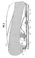
- the seat assembly 10 includes a seat cushion support pan 12, a seat cushion 14, a switch actuation lever 16, at least one and preferably two springs 18, and an OP switch 20.
- the seat cushion support pan 12 is of conventional design and adapted for mounting to a seat suspension assembly.
- the pan 12 may be constructed from sheet metal or high strength plastic and preferably has a size and configuration to receive the seat cushion 14 in a snug or press fit manner.
- the seat cushion support pan 12 is mounted to the upper housing 22 of a conventional seat suspension assembly via a central swivel 24 which allows the seat to rotate horizontally in a manner well known in the art.
- the seat cushion 14 is also of conventional design and construction, preferably made from foamed polyurethane resin.
- the cushion 14 may have an insert 26 located adjacent its lower periphery to assist in maintaining the shape of the cushion and in retaining any cover which is upholstered to the cushion.
- the cushion 14 is provided with a chamber 28 located along its bottom to accommodate the switch and lever components of the assembly.
- the lever 16 preferably comprised of a paddle having a broad cushion engaging surface 30.
- the term "paddle” is used here to mean any structure having a relatively broad surface relative to its thickness such as, for example, plates, panels, grills and gratings. It is desirable that the cushion engaging surface has dimensions of length and width in the range of about one-third to one-half the respective dimensions of length and width of the cushion 14. This insures that the presence of the operator even on a side or front edge of the seat will be sensed. Moreover, it is preferred that sharp corners or edges be avoided in the design of the lever to minimize the "feel" of the device with the cushion by the seat occupant.
- the lever 16 is pivotally mounted to the support pan 12 via tabs 32 cooperating with slots 34 in the pan.
- the lever 16 may move between upper and lower positions in accordance with the operation of the invention.
- At least one and preferably two springs 18 are employed to bias the lever 16 toward its upper position. While compression springs are illustrated in the drawings, leaf or torsion springs or other biasing mechanisms and devices well known to those skilled in the art may be employed in the practice of the invention.
- the OP switch 20 is also a conventional device having a button actuator 36 which abuts the cushion support pan 12.
- the OP switch has all of its components, including the button actuator located above the support pan 12. In other words, there are no switch components that extend through or below the support pan. This simplifies the design of the components located immediately below the support pan, such as the upper housing 22, since the OP switch does not interfere with their operation.
- the present design also minimizes the vertical envelope dimension of the seat assembly 10.
- the lever 16 may have a recess 40 at its distal end.
- the recess has a size sufficient to accommodate the proper positioning of the switch 20 and results in the cushion engaging surface having a generally U-shaped configuration.
- the recess 40 is provided with an aperture into which the switch may be press fit or snap fit.
- the recess 40 also includes an opening 42 for passage of the wiring to the switch. It is also desirable to cover the switch actuator with an flexible boot to prevent moisture or water damage to the switch or switch circuitry.
- the chamber 28 has a vertical dimension sufficient so that when the seat is not occupied the springs 18 can bias the lever 16 to its upper position and the switch 20 is inactive. However, when the seat is occupied, the weight of the occupant depresses the cushion and moves the lever, against the biasing action of the springs, toward the lever's lower position, causing the switch to engage the support pan and depress the button actuator.
- the lever 16 be located toward the front of the seat cushion and, most preferably, extending from a base end near the center of the seat toward the front of the seat. It is also preferred to employ the illustrated paddle lever having a forward recess for positioning of the switch and the placement of each spring on opposite sides of the switch adjacent the recess.
Landscapes
- Engineering & Computer Science (AREA)
- Aviation & Aerospace Engineering (AREA)
- Transportation (AREA)
- Mechanical Engineering (AREA)
- Seats For Vehicles (AREA)
- Rotary Switch, Piano Key Switch, And Lever Switch (AREA)
- Chair Legs, Seat Parts, And Backrests (AREA)
- Push-Button Switches (AREA)
Applications Claiming Priority (1)
| Application Number | Priority Date | Filing Date | Title |
|---|---|---|---|
| US10/994,889 US7211753B2 (en) | 2004-11-22 | 2004-11-22 | Vehicle seat assembly with operator presence switch |
Publications (3)
| Publication Number | Publication Date |
|---|---|
| EP1666311A2 EP1666311A2 (en) | 2006-06-07 |
| EP1666311A3 EP1666311A3 (en) | 2007-05-02 |
| EP1666311B1 true EP1666311B1 (en) | 2009-01-21 |
Family
ID=36097275
Family Applications (1)
| Application Number | Title | Priority Date | Filing Date |
|---|---|---|---|
| EP05394033A Expired - Lifetime EP1666311B1 (en) | 2004-11-22 | 2005-11-22 | Vehicle seat assembly with operator presence switch |
Country Status (6)
| Country | Link |
|---|---|
| US (1) | US7211753B2 (enExample) |
| EP (1) | EP1666311B1 (enExample) |
| JP (1) | JP4939801B2 (enExample) |
| CN (1) | CN100417542C (enExample) |
| AT (1) | ATE421446T1 (enExample) |
| DE (1) | DE602005012476D1 (enExample) |
Cited By (3)
| Publication number | Priority date | Publication date | Assignee | Title |
|---|---|---|---|---|
| WO2013178486A1 (en) | 2012-05-30 | 2013-12-05 | Iee International Electronics & Engineering S.A. | Vehicle seat suspension mat |
| US9333878B2 (en) | 2012-05-30 | 2016-05-10 | Iee International Electronics & Engineering S.A. | Vehicle seat suspension mat |
| US9463714B2 (en) | 2012-05-30 | 2016-10-11 | Iee International Electronics And Engineering S.A. | Vehicle seat suspension mat |
Families Citing this family (6)
| Publication number | Priority date | Publication date | Assignee | Title |
|---|---|---|---|---|
| US20110025109A1 (en) * | 2009-07-31 | 2011-02-03 | Steve Ryczek | Mesh Seat for Ride-On Power Equipment |
| FR2952868B1 (fr) * | 2009-11-20 | 2012-12-14 | Faurecia Sieges Automobile | Element de siege de vehicule et siege de vehicule comprenant un tel element de siege |
| US8393432B2 (en) * | 2011-03-18 | 2013-03-12 | Seats, Inc. | Vehicle seat switch actuator |
| TWM430414U (en) * | 2011-08-05 | 2012-06-01 | jin-zeng Wu | Parking safety device for electric motorcycle |
| CN103692911A (zh) * | 2012-09-27 | 2014-04-02 | 光阳工业股份有限公司 | 车辆乘坐检知装置 |
| JP6517524B2 (ja) * | 2015-02-06 | 2019-05-22 | 本田技研工業株式会社 | 乗物用シート |
Family Cites Families (25)
| Publication number | Priority date | Publication date | Assignee | Title |
|---|---|---|---|---|
| US3703618A (en) * | 1971-03-24 | 1972-11-21 | Fred I Lewis | Vehicle seat belt non-use warning signal switch mounting |
| US4629248A (en) * | 1985-06-03 | 1986-12-16 | General Motors Corporation | Thigh support for vehicle seats |
| JPS6345924A (ja) * | 1987-05-21 | 1988-02-26 | Sony Corp | エラ−訂正方法 |
| JPS6470636A (en) * | 1987-09-10 | 1989-03-16 | Toshiba Corp | Air-conditioning machine |
| US4795865A (en) * | 1987-12-10 | 1989-01-03 | Delta Systems, Inc. | Safety switch for automatic de-activation of a motor vehicle |
| US4969533A (en) * | 1988-07-29 | 1990-11-13 | Deere & Company | Work vehicle |
| JP2862276B2 (ja) * | 1989-05-29 | 1999-03-03 | ニチモウ株式会社 | 貫通型無結節網の編網方法および装置 |
| DE4023350C2 (de) * | 1990-07-23 | 2000-02-24 | Grammer Ag | Sitzplatte insbes. für den Fahrersitz eines Nutzfahrzeuges |
| US5146054A (en) * | 1991-09-04 | 1992-09-08 | Illinois Tool Work Inc. | Motion translation mechanism for a vehicle seat switch |
| US5419614A (en) * | 1993-05-25 | 1995-05-30 | Simula Inc. | Crewseat with adjustable lumbar and thigh supports |
| US5424502A (en) * | 1993-07-27 | 1995-06-13 | Delta Systems, Inc. | Quick-install seat switch |
| US5507560A (en) * | 1993-10-12 | 1996-04-16 | Ford Motor Company | Adjustable rotary action switch assembly |
| US5474353A (en) * | 1993-12-01 | 1995-12-12 | Hoover Universal, Inc. | Pivoting seat cushion arrangement for vehicle seat assemblies |
| DE4408481C2 (de) * | 1994-03-14 | 1997-01-23 | Grammer Ag | Sitzplatte, insbesondere für den Fahrersitz eines Nutzfahrzeuges |
| IL109446A (en) * | 1994-04-26 | 1999-09-22 | Israel Aircraft Ind Ltd | Vehicle seat |
| US5558386A (en) * | 1995-04-20 | 1996-09-24 | Chrysler Corporation | Asymmetrical wire hook latch arrangement |
| JPH1134710A (ja) * | 1997-07-24 | 1999-02-09 | Bridgestone Corp | 着座センサ付き座席 |
| US6079738A (en) * | 1997-08-22 | 2000-06-27 | Breed Automotive Technology, Inc. | Occupant presence and position sensing system |
| WO2001000454A1 (en) * | 1999-06-25 | 2001-01-04 | Siemens Automotive Corporation | Weight sensor assembly for determining seat occupant weight |
| US6161891A (en) * | 1999-10-21 | 2000-12-19 | Cts Corporation | Vehicle seat weight sensor |
| US6457545B1 (en) * | 2000-06-05 | 2002-10-01 | Delta Systems, Inc. | Hall effect seat switch |
| US6359245B1 (en) * | 2000-10-18 | 2002-03-19 | Michigan Seat Company | Tractor seat safety system |
| JP3877671B2 (ja) * | 2002-11-11 | 2007-02-07 | 株式会社クボタ | 作業車の着座検出装置 |
| US7053759B2 (en) * | 2003-12-30 | 2006-05-30 | Lear Corporation | Method of determining an equivalent value for a failed sensor in a vehicle seat having an occupancy sensing system |
| US7079016B2 (en) * | 2004-08-31 | 2006-07-18 | General Motors Corporation | Vehicle-based vehicle occupant reminder using weight-based sensor |
-
2004
- 2004-11-22 US US10/994,889 patent/US7211753B2/en not_active Expired - Lifetime
-
2005
- 2005-11-21 JP JP2005336267A patent/JP4939801B2/ja not_active Expired - Fee Related
- 2005-11-22 CN CNB2005101239114A patent/CN100417542C/zh not_active Expired - Fee Related
- 2005-11-22 DE DE602005012476T patent/DE602005012476D1/de not_active Expired - Lifetime
- 2005-11-22 AT AT05394033T patent/ATE421446T1/de not_active IP Right Cessation
- 2005-11-22 EP EP05394033A patent/EP1666311B1/en not_active Expired - Lifetime
Cited By (4)
| Publication number | Priority date | Publication date | Assignee | Title |
|---|---|---|---|---|
| WO2013178486A1 (en) | 2012-05-30 | 2013-12-05 | Iee International Electronics & Engineering S.A. | Vehicle seat suspension mat |
| US9333878B2 (en) | 2012-05-30 | 2016-05-10 | Iee International Electronics & Engineering S.A. | Vehicle seat suspension mat |
| US9463714B2 (en) | 2012-05-30 | 2016-10-11 | Iee International Electronics And Engineering S.A. | Vehicle seat suspension mat |
| US9776530B2 (en) | 2012-05-30 | 2017-10-03 | Iee International Electronics & Engineering S.A. | Vehicle seat suspension mat |
Also Published As
| Publication number | Publication date |
|---|---|
| CN1778606A (zh) | 2006-05-31 |
| CN100417542C (zh) | 2008-09-10 |
| ATE421446T1 (de) | 2009-02-15 |
| DE602005012476D1 (de) | 2009-03-12 |
| EP1666311A2 (en) | 2006-06-07 |
| JP2006142033A (ja) | 2006-06-08 |
| EP1666311A3 (en) | 2007-05-02 |
| US7211753B2 (en) | 2007-05-01 |
| JP4939801B2 (ja) | 2012-05-30 |
| US20060107766A1 (en) | 2006-05-25 |
Similar Documents
| Publication | Publication Date | Title |
|---|---|---|
| EP1666311B1 (en) | Vehicle seat assembly with operator presence switch | |
| US8517471B2 (en) | Seat assembly having a moveable head restraint | |
| EP2216201B1 (en) | Power seat control unit | |
| JP2007535443A (ja) | 一体型の腰部および能動ヘッドレスト装置 | |
| US5124512A (en) | Vehicle seat switch | |
| EP1737313B1 (en) | Slideable armrest | |
| WO2016092585A1 (ja) | 高さ調整機能付きスライド式ヒールパッド | |
| CA1226606A (en) | Switch assemblies | |
| KR19990022986A (ko) | 머리받침 조립체 | |
| EP1836069B1 (en) | An adjustable seat | |
| WO2011107852A1 (en) | Adjustment mechanism for a vehicle seat headrest | |
| US6359245B1 (en) | Tractor seat safety system | |
| CA1191923A (en) | Seat switch assembly | |
| US6849816B2 (en) | Vehicle steering wheel | |
| KR20030031219A (ko) | 자동차의 에어벤트 조절용 노브 어셈블리 | |
| JP2613350B2 (ja) | 各種スイッチを備えたステアリングホイール | |
| JPH08318806A (ja) | 運転席用エアバッグモジュール | |
| JP3639617B2 (ja) | 座席装置 | |
| KR100783900B1 (ko) | 차량용 도어 암레스트 | |
| GB2428189A (en) | Baby vehicle seat with adjustable armrest mechanism | |
| JP2004142643A (ja) | 車両用シートのインターロック装置 | |
| KR200207968Y1 (ko) | 자동차의 프론트시트 위치 조절장치 | |
| JP2007098752A (ja) | 画像形成装置の操作部及び操作部を備えた画像形成装置 | |
| JP2018165121A (ja) | 着座センサ | |
| JP3070425B2 (ja) | 自動車のトリム構造 |
Legal Events
| Date | Code | Title | Description |
|---|---|---|---|
| PUAI | Public reference made under article 153(3) epc to a published international application that has entered the european phase |
Free format text: ORIGINAL CODE: 0009012 |
|
| AK | Designated contracting states |
Kind code of ref document: A2 Designated state(s): AT BE BG CH CY CZ DE DK EE ES FI FR GB GR HU IE IS IT LI LT LU LV MC NL PL PT RO SE SI SK TR |
|
| AX | Request for extension of the european patent |
Extension state: AL BA HR MK YU |
|
| PUAL | Search report despatched |
Free format text: ORIGINAL CODE: 0009013 |
|
| AK | Designated contracting states |
Kind code of ref document: A3 Designated state(s): AT BE BG CH CY CZ DE DK EE ES FI FR GB GR HU IE IS IT LI LT LU LV MC NL PL PT RO SE SI SK TR |
|
| AX | Request for extension of the european patent |
Extension state: AL BA HR MK YU |
|
| 17P | Request for examination filed |
Effective date: 20071102 |
|
| 17Q | First examination report despatched |
Effective date: 20071217 |
|
| AKX | Designation fees paid |
Designated state(s): AT BE BG CH CY CZ DE DK EE ES FI FR GB GR HU IE IS IT LI LT LU LV MC NL PL PT RO SE SI SK TR |
|
| GRAP | Despatch of communication of intention to grant a patent |
Free format text: ORIGINAL CODE: EPIDOSNIGR1 |
|
| GRAS | Grant fee paid |
Free format text: ORIGINAL CODE: EPIDOSNIGR3 |
|
| GRAA | (expected) grant |
Free format text: ORIGINAL CODE: 0009210 |
|
| AK | Designated contracting states |
Kind code of ref document: B1 Designated state(s): AT BE BG CH CY CZ DE DK EE ES FI FR GB GR HU IE IS IT LI LT LU LV MC NL PL PT RO SE SI SK TR |
|
| REG | Reference to a national code |
Ref country code: GB Ref legal event code: FG4D |
|
| REG | Reference to a national code |
Ref country code: CH Ref legal event code: EP |
|
| REG | Reference to a national code |
Ref country code: IE Ref legal event code: FG4D |
|
| REF | Corresponds to: |
Ref document number: 602005012476 Country of ref document: DE Date of ref document: 20090312 Kind code of ref document: P |
|
| PG25 | Lapsed in a contracting state [announced via postgrant information from national office to epo] |
Ref country code: NL Free format text: LAPSE BECAUSE OF FAILURE TO SUBMIT A TRANSLATION OF THE DESCRIPTION OR TO PAY THE FEE WITHIN THE PRESCRIBED TIME-LIMIT Effective date: 20090121 |
|
| NLV1 | Nl: lapsed or annulled due to failure to fulfill the requirements of art. 29p and 29m of the patents act | ||
| PG25 | Lapsed in a contracting state [announced via postgrant information from national office to epo] |
Ref country code: SI Free format text: LAPSE BECAUSE OF FAILURE TO SUBMIT A TRANSLATION OF THE DESCRIPTION OR TO PAY THE FEE WITHIN THE PRESCRIBED TIME-LIMIT Effective date: 20090121 Ref country code: FI Free format text: LAPSE BECAUSE OF FAILURE TO SUBMIT A TRANSLATION OF THE DESCRIPTION OR TO PAY THE FEE WITHIN THE PRESCRIBED TIME-LIMIT Effective date: 20090121 Ref country code: ES Free format text: LAPSE BECAUSE OF FAILURE TO SUBMIT A TRANSLATION OF THE DESCRIPTION OR TO PAY THE FEE WITHIN THE PRESCRIBED TIME-LIMIT Effective date: 20090502 Ref country code: LT Free format text: LAPSE BECAUSE OF FAILURE TO SUBMIT A TRANSLATION OF THE DESCRIPTION OR TO PAY THE FEE WITHIN THE PRESCRIBED TIME-LIMIT Effective date: 20090121 |
|
| PG25 | Lapsed in a contracting state [announced via postgrant information from national office to epo] |
Ref country code: LV Free format text: LAPSE BECAUSE OF FAILURE TO SUBMIT A TRANSLATION OF THE DESCRIPTION OR TO PAY THE FEE WITHIN THE PRESCRIBED TIME-LIMIT Effective date: 20090121 Ref country code: IS Free format text: LAPSE BECAUSE OF FAILURE TO SUBMIT A TRANSLATION OF THE DESCRIPTION OR TO PAY THE FEE WITHIN THE PRESCRIBED TIME-LIMIT Effective date: 20090521 Ref country code: AT Free format text: LAPSE BECAUSE OF FAILURE TO SUBMIT A TRANSLATION OF THE DESCRIPTION OR TO PAY THE FEE WITHIN THE PRESCRIBED TIME-LIMIT Effective date: 20090121 Ref country code: SE Free format text: LAPSE BECAUSE OF FAILURE TO SUBMIT A TRANSLATION OF THE DESCRIPTION OR TO PAY THE FEE WITHIN THE PRESCRIBED TIME-LIMIT Effective date: 20090421 Ref country code: PT Free format text: LAPSE BECAUSE OF FAILURE TO SUBMIT A TRANSLATION OF THE DESCRIPTION OR TO PAY THE FEE WITHIN THE PRESCRIBED TIME-LIMIT Effective date: 20090622 Ref country code: PL Free format text: LAPSE BECAUSE OF FAILURE TO SUBMIT A TRANSLATION OF THE DESCRIPTION OR TO PAY THE FEE WITHIN THE PRESCRIBED TIME-LIMIT Effective date: 20090121 |
|
| PG25 | Lapsed in a contracting state [announced via postgrant information from national office to epo] |
Ref country code: BE Free format text: LAPSE BECAUSE OF FAILURE TO SUBMIT A TRANSLATION OF THE DESCRIPTION OR TO PAY THE FEE WITHIN THE PRESCRIBED TIME-LIMIT Effective date: 20090121 |
|
| PG25 | Lapsed in a contracting state [announced via postgrant information from national office to epo] |
Ref country code: CZ Free format text: LAPSE BECAUSE OF FAILURE TO SUBMIT A TRANSLATION OF THE DESCRIPTION OR TO PAY THE FEE WITHIN THE PRESCRIBED TIME-LIMIT Effective date: 20090121 Ref country code: EE Free format text: LAPSE BECAUSE OF FAILURE TO SUBMIT A TRANSLATION OF THE DESCRIPTION OR TO PAY THE FEE WITHIN THE PRESCRIBED TIME-LIMIT Effective date: 20090121 Ref country code: DK Free format text: LAPSE BECAUSE OF FAILURE TO SUBMIT A TRANSLATION OF THE DESCRIPTION OR TO PAY THE FEE WITHIN THE PRESCRIBED TIME-LIMIT Effective date: 20090121 |
|
| PLBE | No opposition filed within time limit |
Free format text: ORIGINAL CODE: 0009261 |
|
| STAA | Information on the status of an ep patent application or granted ep patent |
Free format text: STATUS: NO OPPOSITION FILED WITHIN TIME LIMIT |
|
| PG25 | Lapsed in a contracting state [announced via postgrant information from national office to epo] |
Ref country code: RO Free format text: LAPSE BECAUSE OF FAILURE TO SUBMIT A TRANSLATION OF THE DESCRIPTION OR TO PAY THE FEE WITHIN THE PRESCRIBED TIME-LIMIT Effective date: 20090121 Ref country code: SK Free format text: LAPSE BECAUSE OF FAILURE TO SUBMIT A TRANSLATION OF THE DESCRIPTION OR TO PAY THE FEE WITHIN THE PRESCRIBED TIME-LIMIT Effective date: 20090121 |
|
| 26N | No opposition filed |
Effective date: 20091022 |
|
| PG25 | Lapsed in a contracting state [announced via postgrant information from national office to epo] |
Ref country code: BG Free format text: LAPSE BECAUSE OF FAILURE TO SUBMIT A TRANSLATION OF THE DESCRIPTION OR TO PAY THE FEE WITHIN THE PRESCRIBED TIME-LIMIT Effective date: 20090421 |
|
| PG25 | Lapsed in a contracting state [announced via postgrant information from national office to epo] |
Ref country code: MC Free format text: LAPSE BECAUSE OF NON-PAYMENT OF DUE FEES Effective date: 20091130 |
|
| REG | Reference to a national code |
Ref country code: CH Ref legal event code: PL |
|
| REG | Reference to a national code |
Ref country code: FR Ref legal event code: ST Effective date: 20100730 |
|
| PG25 | Lapsed in a contracting state [announced via postgrant information from national office to epo] |
Ref country code: IE Free format text: LAPSE BECAUSE OF NON-PAYMENT OF DUE FEES Effective date: 20091122 Ref country code: GR Free format text: LAPSE BECAUSE OF FAILURE TO SUBMIT A TRANSLATION OF THE DESCRIPTION OR TO PAY THE FEE WITHIN THE PRESCRIBED TIME-LIMIT Effective date: 20090422 Ref country code: FR Free format text: LAPSE BECAUSE OF NON-PAYMENT OF DUE FEES Effective date: 20091130 Ref country code: CH Free format text: LAPSE BECAUSE OF NON-PAYMENT OF DUE FEES Effective date: 20091130 Ref country code: LI Free format text: LAPSE BECAUSE OF NON-PAYMENT OF DUE FEES Effective date: 20091130 |
|
| PG25 | Lapsed in a contracting state [announced via postgrant information from national office to epo] |
Ref country code: IT Free format text: LAPSE BECAUSE OF FAILURE TO SUBMIT A TRANSLATION OF THE DESCRIPTION OR TO PAY THE FEE WITHIN THE PRESCRIBED TIME-LIMIT Effective date: 20090121 |
|
| PG25 | Lapsed in a contracting state [announced via postgrant information from national office to epo] |
Ref country code: LU Free format text: LAPSE BECAUSE OF NON-PAYMENT OF DUE FEES Effective date: 20091122 |
|
| PG25 | Lapsed in a contracting state [announced via postgrant information from national office to epo] |
Ref country code: HU Free format text: LAPSE BECAUSE OF FAILURE TO SUBMIT A TRANSLATION OF THE DESCRIPTION OR TO PAY THE FEE WITHIN THE PRESCRIBED TIME-LIMIT Effective date: 20090722 |
|
| PG25 | Lapsed in a contracting state [announced via postgrant information from national office to epo] |
Ref country code: TR Free format text: LAPSE BECAUSE OF FAILURE TO SUBMIT A TRANSLATION OF THE DESCRIPTION OR TO PAY THE FEE WITHIN THE PRESCRIBED TIME-LIMIT Effective date: 20090121 |
|
| PG25 | Lapsed in a contracting state [announced via postgrant information from national office to epo] |
Ref country code: CY Free format text: LAPSE BECAUSE OF FAILURE TO SUBMIT A TRANSLATION OF THE DESCRIPTION OR TO PAY THE FEE WITHIN THE PRESCRIBED TIME-LIMIT Effective date: 20090121 |
|
| PGFP | Annual fee paid to national office [announced via postgrant information from national office to epo] |
Ref country code: GB Payment date: 20230928 Year of fee payment: 19 |
|
| P01 | Opt-out of the competence of the unified patent court (upc) registered |
Effective date: 20231004 |
|
| PGFP | Annual fee paid to national office [announced via postgrant information from national office to epo] |
Ref country code: DE Payment date: 20230926 Year of fee payment: 19 |
|
| REG | Reference to a national code |
Ref country code: DE Ref legal event code: R119 Ref document number: 602005012476 Country of ref document: DE |
|
| GBPC | Gb: european patent ceased through non-payment of renewal fee |
Effective date: 20241122 |
|
| PG25 | Lapsed in a contracting state [announced via postgrant information from national office to epo] |
Ref country code: DE Free format text: LAPSE BECAUSE OF NON-PAYMENT OF DUE FEES Effective date: 20250603 |
|
| PG25 | Lapsed in a contracting state [announced via postgrant information from national office to epo] |
Ref country code: GB Free format text: LAPSE BECAUSE OF NON-PAYMENT OF DUE FEES Effective date: 20241122 |