EP1663506B1 - Distributeur pour injection concentree - Google Patents
Distributeur pour injection concentree Download PDFInfo
- Publication number
- EP1663506B1 EP1663506B1 EP04774963A EP04774963A EP1663506B1 EP 1663506 B1 EP1663506 B1 EP 1663506B1 EP 04774963 A EP04774963 A EP 04774963A EP 04774963 A EP04774963 A EP 04774963A EP 1663506 B1 EP1663506 B1 EP 1663506B1
- Authority
- EP
- European Patent Office
- Prior art keywords
- dispenser
- foam
- outlet
- liquid
- outflow channel
- Prior art date
- Legal status (The legal status is an assumption and is not a legal conclusion. Google has not performed a legal analysis and makes no representation as to the accuracy of the status listed.)
- Expired - Lifetime
Links
- 238000002347 injection Methods 0.000 title description 4
- 239000007924 injection Substances 0.000 title description 4
- 239000007788 liquid Substances 0.000 claims abstract description 64
- 238000004891 communication Methods 0.000 claims abstract description 11
- 239000006260 foam Substances 0.000 claims description 23
- 230000003068 static effect Effects 0.000 claims description 5
- 239000007921 spray Substances 0.000 description 8
- 230000006835 compression Effects 0.000 description 7
- 238000007906 compression Methods 0.000 description 7
- 238000002474 experimental method Methods 0.000 description 2
- 238000007789 sealing Methods 0.000 description 2
- 238000010276 construction Methods 0.000 description 1
- 230000000694 effects Effects 0.000 description 1
- 238000004880 explosion Methods 0.000 description 1
- 238000005187 foaming Methods 0.000 description 1
- 238000004519 manufacturing process Methods 0.000 description 1
- 239000000203 mixture Substances 0.000 description 1
Images


Classifications
-
- B—PERFORMING OPERATIONS; TRANSPORTING
- B05—SPRAYING OR ATOMISING IN GENERAL; APPLYING FLUENT MATERIALS TO SURFACES, IN GENERAL
- B05B—SPRAYING APPARATUS; ATOMISING APPARATUS; NOZZLES
- B05B7/00—Spraying apparatus for discharge of liquids or other fluent materials from two or more sources, e.g. of liquid and air, of powder and gas
- B05B7/0018—Spraying apparatus for discharge of liquids or other fluent materials from two or more sources, e.g. of liquid and air, of powder and gas with devices for making foam
- B05B7/0025—Spraying apparatus for discharge of liquids or other fluent materials from two or more sources, e.g. of liquid and air, of powder and gas with devices for making foam with a compressed gas supply
- B05B7/0031—Spraying apparatus for discharge of liquids or other fluent materials from two or more sources, e.g. of liquid and air, of powder and gas with devices for making foam with a compressed gas supply with disturbing means promoting mixing, e.g. balls, crowns
- B05B7/0037—Spraying apparatus for discharge of liquids or other fluent materials from two or more sources, e.g. of liquid and air, of powder and gas with devices for making foam with a compressed gas supply with disturbing means promoting mixing, e.g. balls, crowns including sieves, porous members or the like
-
- B—PERFORMING OPERATIONS; TRANSPORTING
- B05—SPRAYING OR ATOMISING IN GENERAL; APPLYING FLUENT MATERIALS TO SURFACES, IN GENERAL
- B05B—SPRAYING APPARATUS; ATOMISING APPARATUS; NOZZLES
- B05B11/00—Single-unit hand-held apparatus in which flow of contents is produced by the muscular force of the operator at the moment of use
- B05B11/01—Single-unit hand-held apparatus in which flow of contents is produced by the muscular force of the operator at the moment of use characterised by the means producing the flow
- B05B11/10—Pump arrangements for transferring the contents from the container to a pump chamber by a sucking effect and forcing the contents out through the dispensing nozzle
- B05B11/1087—Combination of liquid and air pumps
-
- Y—GENERAL TAGGING OF NEW TECHNOLOGICAL DEVELOPMENTS; GENERAL TAGGING OF CROSS-SECTIONAL TECHNOLOGIES SPANNING OVER SEVERAL SECTIONS OF THE IPC; TECHNICAL SUBJECTS COVERED BY FORMER USPC CROSS-REFERENCE ART COLLECTIONS [XRACs] AND DIGESTS
- Y10—TECHNICAL SUBJECTS COVERED BY FORMER USPC
- Y10T—TECHNICAL SUBJECTS COVERED BY FORMER US CLASSIFICATION
- Y10T137/00—Fluid handling
- Y10T137/8593—Systems
- Y10T137/87571—Multiple inlet with single outlet
- Y10T137/87587—Combining by aspiration
- Y10T137/87643—With condition responsive valve
Definitions
- the invention relates to a dispenser according to claim 1.
- Such a dispenser can be used to dispense a spray or a foam.
- Such a dispenser preferably produces a spray or foam of the highest possible quality, which entails the air bubbles in the spray or the foam being distributed as finely and uniformly as possible.
- a dispenser according to the preamble of claim 1 is known from US 4,057,176.
- the object of the present invention is to provide an improved dispenser of the above type.
- the present invention provides for this purpose a dispenser in which the outlet valve of the air pump is adjacent to the outlet of the liquid pump and formed by a flexible wall projecting substantially transversely of the liquid flow.
- the air in the air pump is compressed, and the pressure therefore increases. When a determined pressure difference is reached over the air valve, it will open.
- the resistance which must be overcome is here the valve resistance and the underlying liquid pressure of liquid flowing past the valve.
- the air can hereby be injected under great pressure directly into the liquid.
- a spray or foam of improved quality can hereby be obtained.
- the flexible wall is movable in direction of the liquid flow. In the case of some liquids a sudden opening of the air valve to generate an "explosion" of air is found to be necessary to obtain a good foam or spray.
- An outlet valve for air according to the invention can be manufactured in relatively simple and inexpensive manner.
- the outlet valve of the air pump is preferably positioned relative to the outlet of the liquid pump such that when the valve is opened the air is introduced almost transversely of the liquid flow.
- the outlet of the liquid pump comprises a liquid chamber which, as seen in flow direction, is situated after the outlet valve of the liquid pump and which is provided with a central opening which debouches in the mixing chamber.
- the liquid chamber is filled with liquid from the liquid container. Via the central opening in the liquid chamber the liquid flows into the mixing chamber where, after sufficient build-up of pressure, air is introduced into the liquid.
- the mixing chamber preferably comprises a central outlet opening which debouches in the outflow channel of the dispensing part.
- the air-liquid mixture is thus forced to leave the mixing chamber through a relatively small opening. This also enhances the quality of the foam or the spray.
- a flexible wall is arranged between the liquid chamber and the mixing chamber. In the static situation the valve seals around the central outlet opening of the mixing chamber.
- the central opening of the liquid chamber is preferably in open communication with the outflow channel of the dispensing part. Liquid leaves the liquid chamber through the central opening in the direction of the outflow channel.
- the dispenser according to the invention is particularly intended as foam dispenser, wherein a foam-forming element is arranged in the outflow channel.
- the foam-forming element is preferably arranged in the outflow channel such that the foam flowing through the outflow channel passes through the foam-forming element at least twice.
- a finer and more uniform foam is hereby found to result which is unsurpassed by any known foam-forming unit.
- the production process is furthermore simpler since only one foam-forming element is arranged for two passages, which has the effect of saving costs.
- a further foam-forming element can be arranged, as seen in the flow direction, before or after the foam-forming element that is passed through twice.
- the final foam-forming element as seen in the flow direction, is preferably arranged in the outflow opening.
- the foam-forming element forms resistance at the outer end of the dispensing part, so that the foam does not spurt out of the outflow channel, and thereby remains more stable.
- the invention relates to a dispenser assembly consisting of a liquid container and a dispenser according to the invention.
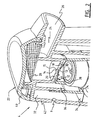
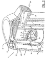
- a dispenser assembly 1 comprises a cylindrical liquid container 2 which has therein a liquid 3 for atomizing or foaming and on which is arranged a dispenser 4 (figure 1).
- Dispenser 4 comprises a pump 6 for air and a pump 8 for liquid, which are each provided with an inlet and an outlet.
- Air pump 6 is in communication with the environment via opening 9 (figure 2), while liquid pump 8 is in communication with the content 3 of liquid container 2 via hose 10.
- Dispenser 4 further comprises a mixing chamber 14 which is in communication with both the air pump 6 and the liquid pump 8.
- the outlet of mixing chamber 14 is formed by a central outlet opening 15 in wall 20.
- the outlet of liquid pump 8 comprises an outlet valve 16 and a liquid chamber 12 which is located thereabove and provided with a central opening 13 debouching in mixing chamber 14.
- An outlet valve 18 for air is located in the outlet of air pump 6 (figure 2).
- the top part of the assembly comprises a dispensing part 22, comprising an outflow channel 24 with an outflow opening 26.
- Outflow channel 24 runs from mixing chamber 14 to outflow opening 26.
- In this channel 24 are arranged one (figure 2) or two (figure 3) foam-forming elements, in the shown preferred embodiment in the form of relatively fine-mesh screens 28,30. Reference is made in respect of these screens, and in particular in respect of specific dimensioning thereof, to patent application NL 1022633, the content of which is incorporated herein.
- the opening 9 for admitting air into air pump 6 is provided in dispensing part 22.
- the inlet of air pump 6 further comprises an air chamber 32.
- the air inlet is bounded by inlet valve 34.
- a compression chamber 36 for air is arranged between inlet valve 34 and outlet valve 18 for air.
- the outlet valve 18 for air is formed by a flexible wall which forms a wall for both liquid chamber 12 and mixing chamber 14. In the static situation the flexible wall 18 seals round the central outlet opening 15 of mixing chamber 14.
- the flexible wall is provided with central opening 13 which forms the outlet of liquid chamber 12. This central opening 13 is in open communication with outflow channel 24 of dispensing part 22 via mixing chamber 14 and the central outlet opening 15 of mixing chamber 14.
- stop means 38 On the underside of flexible wall 18 there are provided stop means 38 with which the outlet valve 16 for liquid comes into contact in the maximum opened position. Stop means 38 serve to prevent the outlet valve 16 for liquid influencing the operation of outlet valve 18 for air. These stops also ensure that the outlet valve 16 for liquid does not close off the liquid flow. During the downward stroke of dispenser 4 the outlet valve 16 is lifted by the liquid flow. These ribs 38 are arranged to prevent the valve 16 sealing the outflow opening 13.
- dispenser 4 and assembly 1 are further constructed is described and shown in international patent application WO 02/42005 of applicant. The content hereof is likewise incorporated.
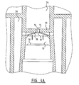
- FIG 4A the outlet valve 18 for air is shown in the static situation.
- the valve 18 seals round outlet opening 15 of mixing chamber 14.
- Air is situated in compression space 36 and owing to the sealing cannot displace to mixing chamber 14.
- Liquid is situated in liquid chamber 12.
- the pressure in the liquid chamber is therefore equal to atmospheric pressure.
- Dispensing part 22 is hereby moved downward relative to container 12 while co-displacing the pistons (not shown) of air pump 6 and liquid pump 8.
- the central outlet opening 15 of mixing chamber 14 preferably has a diameter of between about 0.5 and 4 mm, more preferably a diameter of between about 1 and 2 mm.
- the highly concentrated injection of air into the liquid channel creates an intensive mixing. It has been shown experimentally that this produces a higher quality of foam. It is possible, owing to pressure differences over air valve 18 during injection, that there occurs high-frequency opening and closing of valve 18.
Landscapes
- Containers And Packaging Bodies Having A Special Means To Remove Contents (AREA)
- Closures For Containers (AREA)
- Injection Moulding Of Plastics Or The Like (AREA)
- Feeding, Discharge, Calcimining, Fusing, And Gas-Generation Devices (AREA)
- External Artificial Organs (AREA)
Claims (12)
- Distributeur (4), particulièrement approprié pour un récipient de liquide (2), comprenant :- une pompe à liquide (8) munie d'une entrée ayant une soupape d'entrée et d'une sortie ayant une soupape de sortie (16),- une pompe à air (6) munie d'une entrée ayant une soupape d'entrée (34) et d'une sortie ayant une soupape de sortie (18),- une chambre de mélange (14) qui est en communication avec la sortie de chaque pompe, et- une partie de distribution (22) munie d'un canal d'écoulement vers l'extérieur (24) avec une ouverture d'écoulement vers l'extérieur (26), dans laquelle le canal d'écoulement vers l'extérieur est en communication avec la chambre de mélange,- la soupape de sortie de la pompe à air est adjacente à la sortie de la pompe à liquide (8) et formée par une paroi flexible, caractérisé en ce que cette paroi flexible (18) fait saillie de manière sensiblement transversale à l'écoulement de liquide.
- Distributeur selon la revendication 1, dans lequel la sortie de la pompe à liquide (8) comprend une chambre de liquide (12) qui, telle que vu dans la direction d'écoulement, est située après la soupape de sortie (16) de la pompe à liquide et est munie d'une ouverture centrale (13) qui débouche dans la chambre de mélange (14).
- Distributeur selon l'une quelconque des revendications précédentes, dans lequel la chambre de mélange (14) comprend une ouverture de sortie centrale (15) qui débouche dans le canal d'écoulement vers l'extérieur (24) de la partie de distribution (22).
- Distributeur selon l'une quelconque des revendications précédentes, dans lequel la paroi flexible (18) est agencée entre la chambre de liquide (12) et la chambre de mélange (14).
- Distributeur selon la revendication 4, dans lequel dans la situation statique la paroi flexible (18) est hermétique autour de l'ouverture de sortie centrale (15) de la chambre de mélange (14).
- Distributeur selon l'une quelconque des revendications 2 à 5, dans lequel l'ouverture centrale (13) de la chambre de liquide (12) est en communication ouverte avec le canal d'écoulement vers l'extérieur (24) de la partie de distribution (22).
- Distributeur de mousse selon l'une quelconque des revendications précédentes, comprenant en outre un élément de formation de mousse (28, 30) agencé dans le canal d'écoulement vers l'extérieur.
- Distributeur de mousse selon la revendication 7, dans lequel l'élément de formation de mousse (28) est agencé dans le canal d'écoulement vers l'extérieur de telle sorte que la mousse s'écoulant à travers le canal d'écoulement vers l'extérieur passe à travers l'élément de formation de mousse au moins deux fois.
- Distributeur de mousse selon la revendication 7 ou 8, dans lequel un autre élément de formation de mousse est agencé, de la manière vue dans la direction d'écoulement, avant l'élément de formation de mousse dans le canal d'écoulement vers l'extérieur.
- Distributeur de mousse selon l'une quelconque des revendications 7 à 9, dans lequel un autre élément de formation de mousse est agencé, de la manière vue dans la direction d'écoulement, après l'élément de formation de mousse ou les éléments de formation de mousse dans le canal d'écoulement vers l'extérieur.
- Distributeur de mousse selon la revendication 10, dans lequel l'élément de formation de mousse final (30) tel que vu dans la direction d'écoulement est agencé dans l'ouverture d'écoulement vers l'extérieur (26).
- Ensemble de distributeur (1) consistant en un récipient de liquide (2) et un distributeur (22), dans lequel le distributeur est formé par un distributeur tel que revendiqué dans l'une quelconque des revendications 1 à 11.
Priority Applications (1)
| Application Number | Priority Date | Filing Date | Title |
|---|---|---|---|
| PL04774963T PL1663506T3 (pl) | 2003-09-23 | 2004-09-23 | Dozownik do skupionego wtrysku |
Applications Claiming Priority (2)
| Application Number | Priority Date | Filing Date | Title |
|---|---|---|---|
| NL1024350A NL1024350C2 (nl) | 2003-09-23 | 2003-09-23 | Afgifte-eenheid voor geconcentreerd injecteren. |
| PCT/NL2004/000660 WO2005028121A1 (fr) | 2003-09-23 | 2004-09-23 | Distributeur pour injection concentree |
Publications (2)
| Publication Number | Publication Date |
|---|---|
| EP1663506A1 EP1663506A1 (fr) | 2006-06-07 |
| EP1663506B1 true EP1663506B1 (fr) | 2007-05-16 |
Family
ID=34374397
Family Applications (1)
| Application Number | Title | Priority Date | Filing Date |
|---|---|---|---|
| EP04774963A Expired - Lifetime EP1663506B1 (fr) | 2003-09-23 | 2004-09-23 | Distributeur pour injection concentree |
Country Status (10)
| Country | Link |
|---|---|
| US (1) | US7726518B2 (fr) |
| EP (1) | EP1663506B1 (fr) |
| JP (1) | JP4726790B2 (fr) |
| CN (1) | CN1902007B (fr) |
| AT (1) | ATE362401T1 (fr) |
| CA (1) | CA2542183C (fr) |
| DE (1) | DE602004006521T2 (fr) |
| NL (1) | NL1024350C2 (fr) |
| PL (1) | PL1663506T3 (fr) |
| WO (1) | WO2005028121A1 (fr) |
Cited By (1)
| Publication number | Priority date | Publication date | Assignee | Title |
|---|---|---|---|---|
| JP2007508127A (ja) * | 2003-09-23 | 2007-04-05 | ケルテック・ベスローテン・フエンノートシャップ | 濃縮注入のためのディスペンサ |
Families Citing this family (20)
| Publication number | Priority date | Publication date | Assignee | Title |
|---|---|---|---|---|
| NL1030361C2 (nl) * | 2005-11-07 | 2007-05-08 | Keltec B V | Afgifte-eenheid met verbeterde luchttoevoer. |
| ATE484341T1 (de) * | 2006-07-11 | 2010-10-15 | Rexam Airspray Nv | Schaumspender |
| US7850049B2 (en) * | 2008-01-24 | 2010-12-14 | Gojo Industries, Inc. | Foam pump with improved piston structure |
| USD651918S1 (en) * | 2010-02-08 | 2012-01-10 | The Procter & Gamble Company | Dispensing bottle |
| EP2544662B1 (fr) | 2010-03-10 | 2020-05-20 | Nuvo Pharmaceuticals Inc. | Formulation expansible |
| JP5674138B2 (ja) * | 2011-01-31 | 2015-02-25 | 株式会社吉野工業所 | 泡吐出器 |
| AU2012315361A1 (en) | 2011-09-30 | 2014-04-17 | Owens Corning Intellectual Capital, Llc | Method of forming a web from fibrous materails |
| US12590393B2 (en) | 2011-09-30 | 2026-03-31 | Owens Corning Intellectual Capital, Llc | Method of forming a web from fibrous materials |
| US20130299517A1 (en) * | 2012-05-09 | 2013-11-14 | Gojo Industries, Inc. | Pull-activated foam pumps, dispensers and refill units |
| US9307871B2 (en) | 2012-08-30 | 2016-04-12 | Gojo Industries, Inc. | Horizontal pumps, refill units and foam dispensers |
| WO2014099228A1 (fr) * | 2012-12-20 | 2014-06-26 | Arminak & Associates, Llc | Distributeur de mousse à clapet-piston intégré |
| US20140367419A1 (en) * | 2013-06-14 | 2014-12-18 | Gojo Industries, Inc. | Foam cartridges, pumps, refill units and foam dispensers utilizing the same |
| USD727168S1 (en) * | 2013-09-19 | 2015-04-21 | The Procter & Gamble Company | Cosmetic product package |
| WO2015179555A1 (fr) | 2014-05-20 | 2015-11-26 | Gojo Industries, Inc. | Systemes d'administration de fluide en deux parties |
| ES2763098T3 (es) * | 2014-08-05 | 2020-05-27 | Coop Goizper S | Dispositivo de pulverización a presión |
| USD980069S1 (en) | 2020-07-14 | 2023-03-07 | Ball Corporation | Metallic dispensing lid |
| EP4263065B1 (fr) * | 2020-12-15 | 2024-07-17 | Unilever IP Holdings B.V. | Pulvérisateur |
| US12168551B2 (en) | 2021-03-01 | 2024-12-17 | Ball Corporation | Metal container and end closure with seal |
| IL313184A (en) | 2021-11-29 | 2024-07-01 | Ironwood Pharmaceuticals Inc | Pharmaceutical compositions for the treatment of visceral pain |
| WO2026050206A1 (fr) | 2024-08-27 | 2026-03-05 | Ironwood Pharmaceuticals, Inc. | Combinaisons d'agonistes du récepteur de glp-1 et de guanylate cyclase c (gc-c) |
Family Cites Families (14)
| Publication number | Priority date | Publication date | Assignee | Title |
|---|---|---|---|---|
| AU1577776A (en) * | 1975-07-18 | 1978-01-12 | Plastic Research Products | Manually operated spray |
| US4057176A (en) * | 1975-07-18 | 1977-11-08 | Plastic Research Products, Inc. | Manually operated spray pump |
| JPH0759187B2 (ja) * | 1986-09-19 | 1995-06-28 | 新エネルギー・産業技術総合開発機構 | 糖蜜からのエタノ−ル製造に適した細菌 |
| JPH0615891Y2 (ja) * | 1986-10-31 | 1994-04-27 | 高圧化工株式会社 | 発泡性液体の小出し容器 |
| US5348189A (en) * | 1991-04-10 | 1994-09-20 | Bespak Plc | Air purge pump dispenser |
| DE9407178U1 (de) * | 1994-05-02 | 1994-07-07 | Reidel, Hermann, 63791 Karlstein | Vorrichtung zur Erzeugung und Abgabe von Schaum |
| NL1012419C2 (nl) * | 1999-06-23 | 2000-12-28 | Airspray Nv | Spuitbus voor het afgeven van een vloeistof. |
| JP3942002B2 (ja) * | 2000-04-28 | 2007-07-11 | 株式会社吉野工業所 | ポンプ容器 |
| US6612468B2 (en) * | 2000-09-15 | 2003-09-02 | Rieke Corporation | Dispenser pumps |
| NL1016694C2 (nl) | 2000-11-23 | 2002-05-24 | Keltub B V | Schuimvormingseenheid. |
| JP4811891B2 (ja) * | 2000-11-29 | 2011-11-09 | 大和製罐株式会社 | ポンプ式吐出容器 |
| EP1199105B1 (fr) * | 2001-07-17 | 2002-08-14 | Guala Dispensing S.P.A. | Dispositif de moussage |
| NL1024350C2 (nl) * | 2003-09-23 | 2005-03-24 | R & D Injector Ag | Afgifte-eenheid voor geconcentreerd injecteren. |
| JP2005262202A (ja) * | 2004-02-20 | 2005-09-29 | Yoshino Kogyosho Co Ltd | フォーマーディスペンサ |
-
2003
- 2003-09-23 NL NL1024350A patent/NL1024350C2/nl active Search and Examination
-
2004
- 2004-09-23 WO PCT/NL2004/000660 patent/WO2005028121A1/fr not_active Ceased
- 2004-09-23 CN CN2004800312188A patent/CN1902007B/zh not_active Expired - Fee Related
- 2004-09-23 PL PL04774963T patent/PL1663506T3/pl unknown
- 2004-09-23 AT AT04774963T patent/ATE362401T1/de not_active IP Right Cessation
- 2004-09-23 DE DE200460006521 patent/DE602004006521T2/de not_active Expired - Lifetime
- 2004-09-23 EP EP04774963A patent/EP1663506B1/fr not_active Expired - Lifetime
- 2004-09-23 US US10/573,124 patent/US7726518B2/en active Active
- 2004-09-23 JP JP2006527930A patent/JP4726790B2/ja not_active Expired - Fee Related
- 2004-09-23 CA CA2542183A patent/CA2542183C/fr not_active Expired - Fee Related
Non-Patent Citations (1)
| Title |
|---|
| None * |
Cited By (1)
| Publication number | Priority date | Publication date | Assignee | Title |
|---|---|---|---|---|
| JP2007508127A (ja) * | 2003-09-23 | 2007-04-05 | ケルテック・ベスローテン・フエンノートシャップ | 濃縮注入のためのディスペンサ |
Also Published As
| Publication number | Publication date |
|---|---|
| NL1024350C2 (nl) | 2005-03-24 |
| DE602004006521T2 (de) | 2008-01-17 |
| CN1902007A (zh) | 2007-01-24 |
| CN1902007B (zh) | 2012-08-15 |
| PL1663506T3 (pl) | 2008-01-31 |
| US7726518B2 (en) | 2010-06-01 |
| JP4726790B2 (ja) | 2011-07-20 |
| WO2005028121A1 (fr) | 2005-03-31 |
| CA2542183A1 (fr) | 2005-03-31 |
| ATE362401T1 (de) | 2007-06-15 |
| CA2542183C (fr) | 2014-01-28 |
| EP1663506A1 (fr) | 2006-06-07 |
| US20080237265A1 (en) | 2008-10-02 |
| JP2007508127A (ja) | 2007-04-05 |
| DE602004006521D1 (de) | 2007-06-28 |
Similar Documents
| Publication | Publication Date | Title |
|---|---|---|
| EP1663506B1 (fr) | Distributeur pour injection concentree | |
| KR100886335B1 (ko) | 폼 형성 유닛 | |
| JP3395065B2 (ja) | 泡分与装置及びこの種の分与装置用の押しボタン | |
| KR100311592B1 (ko) | 거품분출펌프부착용기 | |
| US4219159A (en) | Foam device | |
| CN101370597B (zh) | 用于分配泡沫的分配装置及用于形成泡沫的组件 | |
| RU2267452C2 (ru) | Сильфонный насос для подачи газожидкостных смесей | |
| US7673854B2 (en) | Foam forming unit | |
| HUP0303519A2 (hu) | Szórófej hab kiadagolására és habkiadagoló | |
| CA2514016A1 (fr) | Buse pour vaporisation en fines gouttelettes | |
| KR20100015848A (ko) | 다이어프램 밸브를 갖춘 액체 분배장치와 그 밸브의 조립방법 | |
| CA2328931C (fr) | Dispositif de pulverisation de mousse | |
| US6997353B2 (en) | Fluid product dispenser | |
| WO2009130462A1 (fr) | Distributeur de fluide de type pompe manuelle | |
| US7967171B2 (en) | Air foaming pump trigger sprayer | |
| JP3213249B2 (ja) | 泡噴出ポンプ容器 | |
| KR102886113B1 (ko) | 노즐헤드 교체방식의 방아쇠형 펌핑토출장치 | |
| JPH0811955A (ja) | 泡噴出容器 |
Legal Events
| Date | Code | Title | Description |
|---|---|---|---|
| PUAI | Public reference made under article 153(3) epc to a published international application that has entered the european phase |
Free format text: ORIGINAL CODE: 0009012 |
|
| 17P | Request for examination filed |
Effective date: 20060321 |
|
| AK | Designated contracting states |
Kind code of ref document: A1 Designated state(s): AT BE BG CH CY CZ DE DK EE ES FI FR GB GR HU IE IT LI LU MC NL PL PT RO SE SI SK TR |
|
| GRAP | Despatch of communication of intention to grant a patent |
Free format text: ORIGINAL CODE: EPIDOSNIGR1 |
|
| DAX | Request for extension of the european patent (deleted) | ||
| GRAS | Grant fee paid |
Free format text: ORIGINAL CODE: EPIDOSNIGR3 |
|
| GRAA | (expected) grant |
Free format text: ORIGINAL CODE: 0009210 |
|
| AK | Designated contracting states |
Kind code of ref document: B1 Designated state(s): AT BE BG CH CY CZ DE DK EE ES FI FR GB GR HU IE IT LI LU MC NL PL PT RO SE SI SK TR |
|
| PG25 | Lapsed in a contracting state [announced via postgrant information from national office to epo] |
Ref country code: FI Free format text: LAPSE BECAUSE OF FAILURE TO SUBMIT A TRANSLATION OF THE DESCRIPTION OR TO PAY THE FEE WITHIN THE PRESCRIBED TIME-LIMIT Effective date: 20070516 |
|
| REG | Reference to a national code |
Ref country code: GB Ref legal event code: FG4D |
|
| REG | Reference to a national code |
Ref country code: CH Ref legal event code: EP |
|
| REG | Reference to a national code |
Ref country code: IE Ref legal event code: FG4D |
|
| REF | Corresponds to: |
Ref document number: 602004006521 Country of ref document: DE Date of ref document: 20070628 Kind code of ref document: P |
|
| PG25 | Lapsed in a contracting state [announced via postgrant information from national office to epo] |
Ref country code: SE Free format text: LAPSE BECAUSE OF FAILURE TO SUBMIT A TRANSLATION OF THE DESCRIPTION OR TO PAY THE FEE WITHIN THE PRESCRIBED TIME-LIMIT Effective date: 20070816 |
|
| PG25 | Lapsed in a contracting state [announced via postgrant information from national office to epo] |
Ref country code: ES Free format text: LAPSE BECAUSE OF FAILURE TO SUBMIT A TRANSLATION OF THE DESCRIPTION OR TO PAY THE FEE WITHIN THE PRESCRIBED TIME-LIMIT Effective date: 20070827 |
|
| REG | Reference to a national code |
Ref country code: CH Ref legal event code: NV Representative=s name: ARNOLD & SIEDSMA AG |
|
| ET | Fr: translation filed | ||
| PG25 | Lapsed in a contracting state [announced via postgrant information from national office to epo] |
Ref country code: AT Free format text: LAPSE BECAUSE OF FAILURE TO SUBMIT A TRANSLATION OF THE DESCRIPTION OR TO PAY THE FEE WITHIN THE PRESCRIBED TIME-LIMIT Effective date: 20070516 |
|
| PG25 | Lapsed in a contracting state [announced via postgrant information from national office to epo] |
Ref country code: CZ Free format text: LAPSE BECAUSE OF FAILURE TO SUBMIT A TRANSLATION OF THE DESCRIPTION OR TO PAY THE FEE WITHIN THE PRESCRIBED TIME-LIMIT Effective date: 20070516 Ref country code: BG Free format text: LAPSE BECAUSE OF FAILURE TO SUBMIT A TRANSLATION OF THE DESCRIPTION OR TO PAY THE FEE WITHIN THE PRESCRIBED TIME-LIMIT Effective date: 20070816 Ref country code: DK Free format text: LAPSE BECAUSE OF FAILURE TO SUBMIT A TRANSLATION OF THE DESCRIPTION OR TO PAY THE FEE WITHIN THE PRESCRIBED TIME-LIMIT Effective date: 20070516 Ref country code: PT Free format text: LAPSE BECAUSE OF FAILURE TO SUBMIT A TRANSLATION OF THE DESCRIPTION OR TO PAY THE FEE WITHIN THE PRESCRIBED TIME-LIMIT Effective date: 20071016 Ref country code: SI Free format text: LAPSE BECAUSE OF FAILURE TO SUBMIT A TRANSLATION OF THE DESCRIPTION OR TO PAY THE FEE WITHIN THE PRESCRIBED TIME-LIMIT Effective date: 20070516 |
|
| REG | Reference to a national code |
Ref country code: PL Ref legal event code: T3 |
|
| PG25 | Lapsed in a contracting state [announced via postgrant information from national office to epo] |
Ref country code: SK Free format text: LAPSE BECAUSE OF FAILURE TO SUBMIT A TRANSLATION OF THE DESCRIPTION OR TO PAY THE FEE WITHIN THE PRESCRIBED TIME-LIMIT Effective date: 20070516 |
|
| PLBE | No opposition filed within time limit |
Free format text: ORIGINAL CODE: 0009261 |
|
| STAA | Information on the status of an ep patent application or granted ep patent |
Free format text: STATUS: NO OPPOSITION FILED WITHIN TIME LIMIT |
|
| 26N | No opposition filed |
Effective date: 20080219 |
|
| PG25 | Lapsed in a contracting state [announced via postgrant information from national office to epo] |
Ref country code: GR Free format text: LAPSE BECAUSE OF FAILURE TO SUBMIT A TRANSLATION OF THE DESCRIPTION OR TO PAY THE FEE WITHIN THE PRESCRIBED TIME-LIMIT Effective date: 20070817 Ref country code: MC Free format text: LAPSE BECAUSE OF NON-PAYMENT OF DUE FEES Effective date: 20070930 |
|
| PG25 | Lapsed in a contracting state [announced via postgrant information from national office to epo] |
Ref country code: RO Free format text: LAPSE BECAUSE OF FAILURE TO SUBMIT A TRANSLATION OF THE DESCRIPTION OR TO PAY THE FEE WITHIN THE PRESCRIBED TIME-LIMIT Effective date: 20070516 |
|
| PG25 | Lapsed in a contracting state [announced via postgrant information from national office to epo] |
Ref country code: IE Free format text: LAPSE BECAUSE OF NON-PAYMENT OF DUE FEES Effective date: 20070924 |
|
| PGFP | Annual fee paid to national office [announced via postgrant information from national office to epo] |
Ref country code: CH Payment date: 20080930 Year of fee payment: 5 |
|
| PGFP | Annual fee paid to national office [announced via postgrant information from national office to epo] |
Ref country code: PL Payment date: 20080902 Year of fee payment: 5 |
|
| PG25 | Lapsed in a contracting state [announced via postgrant information from national office to epo] |
Ref country code: EE Free format text: LAPSE BECAUSE OF FAILURE TO SUBMIT A TRANSLATION OF THE DESCRIPTION OR TO PAY THE FEE WITHIN THE PRESCRIBED TIME-LIMIT Effective date: 20070516 |
|
| PGFP | Annual fee paid to national office [announced via postgrant information from national office to epo] |
Ref country code: BE Payment date: 20081009 Year of fee payment: 5 |
|
| PG25 | Lapsed in a contracting state [announced via postgrant information from national office to epo] |
Ref country code: CY Free format text: LAPSE BECAUSE OF FAILURE TO SUBMIT A TRANSLATION OF THE DESCRIPTION OR TO PAY THE FEE WITHIN THE PRESCRIBED TIME-LIMIT Effective date: 20070516 |
|
| PG25 | Lapsed in a contracting state [announced via postgrant information from national office to epo] |
Ref country code: LU Free format text: LAPSE BECAUSE OF NON-PAYMENT OF DUE FEES Effective date: 20070923 |
|
| PG25 | Lapsed in a contracting state [announced via postgrant information from national office to epo] |
Ref country code: TR Free format text: LAPSE BECAUSE OF FAILURE TO SUBMIT A TRANSLATION OF THE DESCRIPTION OR TO PAY THE FEE WITHIN THE PRESCRIBED TIME-LIMIT Effective date: 20070516 Ref country code: HU Free format text: LAPSE BECAUSE OF FAILURE TO SUBMIT A TRANSLATION OF THE DESCRIPTION OR TO PAY THE FEE WITHIN THE PRESCRIBED TIME-LIMIT Effective date: 20071117 |
|
| BERE | Be: lapsed |
Owner name: KELTEC B.V. Effective date: 20090930 |
|
| REG | Reference to a national code |
Ref country code: CH Ref legal event code: PL |
|
| PG25 | Lapsed in a contracting state [announced via postgrant information from national office to epo] |
Ref country code: BE Free format text: LAPSE BECAUSE OF NON-PAYMENT OF DUE FEES Effective date: 20090930 |
|
| PG25 | Lapsed in a contracting state [announced via postgrant information from national office to epo] |
Ref country code: LI Free format text: LAPSE BECAUSE OF NON-PAYMENT OF DUE FEES Effective date: 20090930 Ref country code: CH Free format text: LAPSE BECAUSE OF NON-PAYMENT OF DUE FEES Effective date: 20090930 |
|
| PG25 | Lapsed in a contracting state [announced via postgrant information from national office to epo] |
Ref country code: PL Free format text: LAPSE BECAUSE OF NON-PAYMENT OF DUE FEES Effective date: 20090923 |
|
| REG | Reference to a national code |
Ref country code: PL Ref legal event code: LAPE |
|
| PGFP | Annual fee paid to national office [announced via postgrant information from national office to epo] |
Ref country code: NL Payment date: 20130926 Year of fee payment: 10 Ref country code: DE Payment date: 20130927 Year of fee payment: 10 |
|
| PGFP | Annual fee paid to national office [announced via postgrant information from national office to epo] |
Ref country code: FR Payment date: 20130919 Year of fee payment: 10 |
|
| PGFP | Annual fee paid to national office [announced via postgrant information from national office to epo] |
Ref country code: IT Payment date: 20130924 Year of fee payment: 10 |
|
| REG | Reference to a national code |
Ref country code: DE Ref legal event code: R119 Ref document number: 602004006521 Country of ref document: DE |
|
| REG | Reference to a national code |
Ref country code: DE Ref legal event code: R119 Ref document number: 602004006521 Country of ref document: DE Effective date: 20150401 |
|
| REG | Reference to a national code |
Ref country code: FR Ref legal event code: ST Effective date: 20150529 |
|
| PG25 | Lapsed in a contracting state [announced via postgrant information from national office to epo] |
Ref country code: NL Free format text: LAPSE BECAUSE OF NON-PAYMENT OF DUE FEES Effective date: 20150401 |
|
| PG25 | Lapsed in a contracting state [announced via postgrant information from national office to epo] |
Ref country code: DE Free format text: LAPSE BECAUSE OF NON-PAYMENT OF DUE FEES Effective date: 20150401 |
|
| PG25 | Lapsed in a contracting state [announced via postgrant information from national office to epo] |
Ref country code: IT Free format text: LAPSE BECAUSE OF NON-PAYMENT OF DUE FEES Effective date: 20140923 Ref country code: FR Free format text: LAPSE BECAUSE OF NON-PAYMENT OF DUE FEES Effective date: 20140930 |
|
| PGFP | Annual fee paid to national office [announced via postgrant information from national office to epo] |
Ref country code: GB Payment date: 20210927 Year of fee payment: 18 |
|
| GBPC | Gb: european patent ceased through non-payment of renewal fee |
Effective date: 20220923 |
|
| PG25 | Lapsed in a contracting state [announced via postgrant information from national office to epo] |
Ref country code: GB Free format text: LAPSE BECAUSE OF NON-PAYMENT OF DUE FEES Effective date: 20220923 |