EP1663506B1 - Dispenser for concentrated injection - Google Patents
Dispenser for concentrated injection Download PDFInfo
- Publication number
- EP1663506B1 EP1663506B1 EP04774963A EP04774963A EP1663506B1 EP 1663506 B1 EP1663506 B1 EP 1663506B1 EP 04774963 A EP04774963 A EP 04774963A EP 04774963 A EP04774963 A EP 04774963A EP 1663506 B1 EP1663506 B1 EP 1663506B1
- Authority
- EP
- European Patent Office
- Prior art keywords
- dispenser
- foam
- outlet
- liquid
- outflow channel
- Prior art date
- Legal status (The legal status is an assumption and is not a legal conclusion. Google has not performed a legal analysis and makes no representation as to the accuracy of the status listed.)
- Expired - Lifetime
Links
- 238000002347 injection Methods 0.000 title description 4
- 239000007924 injection Substances 0.000 title description 4
- 239000007788 liquid Substances 0.000 claims abstract description 64
- 238000004891 communication Methods 0.000 claims abstract description 11
- 239000006260 foam Substances 0.000 claims description 23
- 230000003068 static effect Effects 0.000 claims description 5
- 239000007921 spray Substances 0.000 description 8
- 230000006835 compression Effects 0.000 description 7
- 238000007906 compression Methods 0.000 description 7
- 238000002474 experimental method Methods 0.000 description 2
- 238000007789 sealing Methods 0.000 description 2
- 238000010276 construction Methods 0.000 description 1
- 230000000694 effects Effects 0.000 description 1
- 238000004880 explosion Methods 0.000 description 1
- 238000005187 foaming Methods 0.000 description 1
- 238000004519 manufacturing process Methods 0.000 description 1
- 239000000203 mixture Substances 0.000 description 1
Images


Classifications
-
- B—PERFORMING OPERATIONS; TRANSPORTING
- B05—SPRAYING OR ATOMISING IN GENERAL; APPLYING FLUENT MATERIALS TO SURFACES, IN GENERAL
- B05B—SPRAYING APPARATUS; ATOMISING APPARATUS; NOZZLES
- B05B7/00—Spraying apparatus for discharge of liquids or other fluent materials from two or more sources, e.g. of liquid and air, of powder and gas
- B05B7/0018—Spraying apparatus for discharge of liquids or other fluent materials from two or more sources, e.g. of liquid and air, of powder and gas with devices for making foam
- B05B7/0025—Spraying apparatus for discharge of liquids or other fluent materials from two or more sources, e.g. of liquid and air, of powder and gas with devices for making foam with a compressed gas supply
- B05B7/0031—Spraying apparatus for discharge of liquids or other fluent materials from two or more sources, e.g. of liquid and air, of powder and gas with devices for making foam with a compressed gas supply with disturbing means promoting mixing, e.g. balls, crowns
- B05B7/0037—Spraying apparatus for discharge of liquids or other fluent materials from two or more sources, e.g. of liquid and air, of powder and gas with devices for making foam with a compressed gas supply with disturbing means promoting mixing, e.g. balls, crowns including sieves, porous members or the like
-
- B—PERFORMING OPERATIONS; TRANSPORTING
- B05—SPRAYING OR ATOMISING IN GENERAL; APPLYING FLUENT MATERIALS TO SURFACES, IN GENERAL
- B05B—SPRAYING APPARATUS; ATOMISING APPARATUS; NOZZLES
- B05B11/00—Single-unit hand-held apparatus in which flow of contents is produced by the muscular force of the operator at the moment of use
- B05B11/01—Single-unit hand-held apparatus in which flow of contents is produced by the muscular force of the operator at the moment of use characterised by the means producing the flow
- B05B11/10—Pump arrangements for transferring the contents from the container to a pump chamber by a sucking effect and forcing the contents out through the dispensing nozzle
- B05B11/1087—Combination of liquid and air pumps
-
- Y—GENERAL TAGGING OF NEW TECHNOLOGICAL DEVELOPMENTS; GENERAL TAGGING OF CROSS-SECTIONAL TECHNOLOGIES SPANNING OVER SEVERAL SECTIONS OF THE IPC; TECHNICAL SUBJECTS COVERED BY FORMER USPC CROSS-REFERENCE ART COLLECTIONS [XRACs] AND DIGESTS
- Y10—TECHNICAL SUBJECTS COVERED BY FORMER USPC
- Y10T—TECHNICAL SUBJECTS COVERED BY FORMER US CLASSIFICATION
- Y10T137/00—Fluid handling
- Y10T137/8593—Systems
- Y10T137/87571—Multiple inlet with single outlet
- Y10T137/87587—Combining by aspiration
- Y10T137/87643—With condition responsive valve
Definitions
- the invention relates to a dispenser according to claim 1.
- Such a dispenser can be used to dispense a spray or a foam.
- Such a dispenser preferably produces a spray or foam of the highest possible quality, which entails the air bubbles in the spray or the foam being distributed as finely and uniformly as possible.
- a dispenser according to the preamble of claim 1 is known from US 4,057,176.
- the object of the present invention is to provide an improved dispenser of the above type.
- the present invention provides for this purpose a dispenser in which the outlet valve of the air pump is adjacent to the outlet of the liquid pump and formed by a flexible wall projecting substantially transversely of the liquid flow.
- the air in the air pump is compressed, and the pressure therefore increases. When a determined pressure difference is reached over the air valve, it will open.
- the resistance which must be overcome is here the valve resistance and the underlying liquid pressure of liquid flowing past the valve.
- the air can hereby be injected under great pressure directly into the liquid.
- a spray or foam of improved quality can hereby be obtained.
- the flexible wall is movable in direction of the liquid flow. In the case of some liquids a sudden opening of the air valve to generate an "explosion" of air is found to be necessary to obtain a good foam or spray.
- An outlet valve for air according to the invention can be manufactured in relatively simple and inexpensive manner.
- the outlet valve of the air pump is preferably positioned relative to the outlet of the liquid pump such that when the valve is opened the air is introduced almost transversely of the liquid flow.
- the outlet of the liquid pump comprises a liquid chamber which, as seen in flow direction, is situated after the outlet valve of the liquid pump and which is provided with a central opening which debouches in the mixing chamber.
- the liquid chamber is filled with liquid from the liquid container. Via the central opening in the liquid chamber the liquid flows into the mixing chamber where, after sufficient build-up of pressure, air is introduced into the liquid.
- the mixing chamber preferably comprises a central outlet opening which debouches in the outflow channel of the dispensing part.
- the air-liquid mixture is thus forced to leave the mixing chamber through a relatively small opening. This also enhances the quality of the foam or the spray.
- a flexible wall is arranged between the liquid chamber and the mixing chamber. In the static situation the valve seals around the central outlet opening of the mixing chamber.
- the central opening of the liquid chamber is preferably in open communication with the outflow channel of the dispensing part. Liquid leaves the liquid chamber through the central opening in the direction of the outflow channel.
- the dispenser according to the invention is particularly intended as foam dispenser, wherein a foam-forming element is arranged in the outflow channel.
- the foam-forming element is preferably arranged in the outflow channel such that the foam flowing through the outflow channel passes through the foam-forming element at least twice.
- a finer and more uniform foam is hereby found to result which is unsurpassed by any known foam-forming unit.
- the production process is furthermore simpler since only one foam-forming element is arranged for two passages, which has the effect of saving costs.
- a further foam-forming element can be arranged, as seen in the flow direction, before or after the foam-forming element that is passed through twice.
- the final foam-forming element as seen in the flow direction, is preferably arranged in the outflow opening.
- the foam-forming element forms resistance at the outer end of the dispensing part, so that the foam does not spurt out of the outflow channel, and thereby remains more stable.
- the invention relates to a dispenser assembly consisting of a liquid container and a dispenser according to the invention.
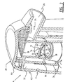
- a dispenser assembly 1 comprises a cylindrical liquid container 2 which has therein a liquid 3 for atomizing or foaming and on which is arranged a dispenser 4 (figure 1).
- Dispenser 4 comprises a pump 6 for air and a pump 8 for liquid, which are each provided with an inlet and an outlet.
- Air pump 6 is in communication with the environment via opening 9 (figure 2), while liquid pump 8 is in communication with the content 3 of liquid container 2 via hose 10.
- Dispenser 4 further comprises a mixing chamber 14 which is in communication with both the air pump 6 and the liquid pump 8.
- the outlet of mixing chamber 14 is formed by a central outlet opening 15 in wall 20.
- the outlet of liquid pump 8 comprises an outlet valve 16 and a liquid chamber 12 which is located thereabove and provided with a central opening 13 debouching in mixing chamber 14.
- An outlet valve 18 for air is located in the outlet of air pump 6 (figure 2).
- the top part of the assembly comprises a dispensing part 22, comprising an outflow channel 24 with an outflow opening 26.
- Outflow channel 24 runs from mixing chamber 14 to outflow opening 26.
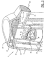
- In this channel 24 are arranged one (figure 2) or two (figure 3) foam-forming elements, in the shown preferred embodiment in the form of relatively fine-mesh screens 28,30. Reference is made in respect of these screens, and in particular in respect of specific dimensioning thereof, to patent application NL 1022633, the content of which is incorporated herein.
- the opening 9 for admitting air into air pump 6 is provided in dispensing part 22.
- the inlet of air pump 6 further comprises an air chamber 32.
- the air inlet is bounded by inlet valve 34.
- a compression chamber 36 for air is arranged between inlet valve 34 and outlet valve 18 for air.
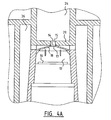
- the outlet valve 18 for air is formed by a flexible wall which forms a wall for both liquid chamber 12 and mixing chamber 14. In the static situation the flexible wall 18 seals round the central outlet opening 15 of mixing chamber 14.
- the flexible wall is provided with central opening 13 which forms the outlet of liquid chamber 12. This central opening 13 is in open communication with outflow channel 24 of dispensing part 22 via mixing chamber 14 and the central outlet opening 15 of mixing chamber 14.
- stop means 38 On the underside of flexible wall 18 there are provided stop means 38 with which the outlet valve 16 for liquid comes into contact in the maximum opened position. Stop means 38 serve to prevent the outlet valve 16 for liquid influencing the operation of outlet valve 18 for air. These stops also ensure that the outlet valve 16 for liquid does not close off the liquid flow. During the downward stroke of dispenser 4 the outlet valve 16 is lifted by the liquid flow. These ribs 38 are arranged to prevent the valve 16 sealing the outflow opening 13.
- dispenser 4 and assembly 1 are further constructed is described and shown in international patent application WO 02/42005 of applicant. The content hereof is likewise incorporated.
- FIG 4A the outlet valve 18 for air is shown in the static situation.
- the valve 18 seals round outlet opening 15 of mixing chamber 14.
- Air is situated in compression space 36 and owing to the sealing cannot displace to mixing chamber 14.
- Liquid is situated in liquid chamber 12.
- the pressure in the liquid chamber is therefore equal to atmospheric pressure.
- Dispensing part 22 is hereby moved downward relative to container 12 while co-displacing the pistons (not shown) of air pump 6 and liquid pump 8.
- the central outlet opening 15 of mixing chamber 14 preferably has a diameter of between about 0.5 and 4 mm, more preferably a diameter of between about 1 and 2 mm.
- the highly concentrated injection of air into the liquid channel creates an intensive mixing. It has been shown experimentally that this produces a higher quality of foam. It is possible, owing to pressure differences over air valve 18 during injection, that there occurs high-frequency opening and closing of valve 18.
Landscapes
- Containers And Packaging Bodies Having A Special Means To Remove Contents (AREA)
- Closures For Containers (AREA)
- Injection Moulding Of Plastics Or The Like (AREA)
- Feeding, Discharge, Calcimining, Fusing, And Gas-Generation Devices (AREA)
- External Artificial Organs (AREA)
Abstract
Description
- The invention relates to a dispenser according to claim 1.
- Such a dispenser can be used to dispense a spray or a foam. Such a dispenser preferably produces a spray or foam of the highest possible quality, which entails the air bubbles in the spray or the foam being distributed as finely and uniformly as possible.
- A dispenser according to the preamble of claim 1 is known from US 4,057,176.
- The object of the present invention is to provide an improved dispenser of the above type.
- The present invention provides for this purpose a dispenser in which the outlet valve of the air pump is adjacent to the outlet of the liquid pump and formed by a flexible wall projecting substantially transversely of the liquid flow.
- The air in the air pump is compressed, and the pressure therefore increases. When a determined pressure difference is reached over the air valve, it will open. The resistance which must be overcome is here the valve resistance and the underlying liquid pressure of liquid flowing past the valve. The air can hereby be injected under great pressure directly into the liquid. Experiments have shown that a spray or foam of improved quality can hereby be obtained. The flexible wall is movable in direction of the liquid flow. In the case of some liquids a sudden opening of the air valve to generate an "explosion" of air is found to be necessary to obtain a good foam or spray. An outlet valve for air according to the invention can be manufactured in relatively simple and inexpensive manner.
- The outlet valve of the air pump is preferably positioned relative to the outlet of the liquid pump such that when the valve is opened the air is introduced almost transversely of the liquid flow. Experiments have once again shown that this enhances the quality of the spray or the foam.
- In a further embodiment according to the invention the outlet of the liquid pump comprises a liquid chamber which, as seen in flow direction, is situated after the outlet valve of the liquid pump and which is provided with a central opening which debouches in the mixing chamber. During compression of the air in the air pump the liquid chamber is filled with liquid from the liquid container. Via the central opening in the liquid chamber the liquid flows into the mixing chamber where, after sufficient build-up of pressure, air is introduced into the liquid.
- The mixing chamber preferably comprises a central outlet opening which debouches in the outflow channel of the dispensing part. The air-liquid mixture is thus forced to leave the mixing chamber through a relatively small opening. This also enhances the quality of the foam or the spray.
- In a preferred embodiment a flexible wall is arranged between the liquid chamber and the mixing chamber. In the static situation the valve seals around the central outlet opening of the mixing chamber.
- The central opening of the liquid chamber is preferably in open communication with the outflow channel of the dispensing part. Liquid leaves the liquid chamber through the central opening in the direction of the outflow channel.
- The dispenser according to the invention is particularly intended as foam dispenser, wherein a foam-forming element is arranged in the outflow channel.
- The foam-forming element is preferably arranged in the outflow channel such that the foam flowing through the outflow channel passes through the foam-forming element at least twice. A finer and more uniform foam is hereby found to result which is unsurpassed by any known foam-forming unit. The production process is furthermore simpler since only one foam-forming element is arranged for two passages, which has the effect of saving costs.
- For a further improvement in the foam quality, a further foam-forming element can be arranged, as seen in the flow direction, before or after the foam-forming element that is passed through twice. In a particularly advantageous embodiment according to the invention, the final foam-forming element, as seen in the flow direction, is preferably arranged in the outflow opening. The foam-forming element forms resistance at the outer end of the dispensing part, so that the foam does not spurt out of the outflow channel, and thereby remains more stable.
- Finally, the invention relates to a dispenser assembly consisting of a liquid container and a dispenser according to the invention.
- The invention will be further elucidated hereinbelow with reference to the accompanying drawings. In the drawings:
- Figure 1 shows a perspective, partly cut-away dispenser assembly according to the invention;
- Figure 2 shows a perspective view in cross-section of a detail of a foam dispenser according to a first embodiment;
- Figure 3 shows a perspective view in cross-section of a detail of a foam dispenser according to a second embodiment;
- Figures 4A and 4B are partly cross-sectional views of the dispenser shown in figures 2 and 3 with respectively closed and open outlet valve for air.
- A dispenser assembly 1 according to the present invention comprises a cylindrical
liquid container 2 which has therein aliquid 3 for atomizing or foaming and on which is arranged a dispenser 4 (figure 1).Dispenser 4 comprises apump 6 for air and apump 8 for liquid, which are each provided with an inlet and an outlet.Air pump 6 is in communication with the environment via opening 9 (figure 2), whileliquid pump 8 is in communication with thecontent 3 ofliquid container 2 viahose 10.Dispenser 4 further comprises amixing chamber 14 which is in communication with both theair pump 6 and theliquid pump 8. The outlet ofmixing chamber 14 is formed by a central outlet opening 15 inwall 20. The outlet ofliquid pump 8 comprises anoutlet valve 16 and aliquid chamber 12 which is located thereabove and provided with acentral opening 13 debouching inmixing chamber 14. Anoutlet valve 18 for air is located in the outlet of air pump 6 (figure 2). - The top part of the assembly comprises a dispensing
part 22, comprising anoutflow channel 24 with anoutflow opening 26.Outflow channel 24 runs frommixing chamber 14 to outflow opening 26. In thischannel 24 are arranged one (figure 2) or two (figure 3) foam-forming elements, in the shown preferred embodiment in the form of relatively fine-mesh screens - The opening 9 for admitting air into
air pump 6 is provided in dispensingpart 22. The inlet ofair pump 6 further comprises anair chamber 32. The air inlet is bounded byinlet valve 34. Acompression chamber 36 for air is arranged betweeninlet valve 34 andoutlet valve 18 for air. - The
outlet valve 18 for air is formed by a flexible wall which forms a wall for bothliquid chamber 12 andmixing chamber 14. In the static situation theflexible wall 18 seals round the central outlet opening 15 ofmixing chamber 14. The flexible wall is provided withcentral opening 13 which forms the outlet ofliquid chamber 12. Thiscentral opening 13 is in open communication withoutflow channel 24 of dispensingpart 22 viamixing chamber 14 and the central outlet opening 15 ofmixing chamber 14. - On the underside of
flexible wall 18 there are provided stop means 38 with which theoutlet valve 16 for liquid comes into contact in the maximum opened position. Stop means 38 serve to prevent theoutlet valve 16 for liquid influencing the operation ofoutlet valve 18 for air. These stops also ensure that theoutlet valve 16 for liquid does not close off the liquid flow. During the downward stroke ofdispenser 4 theoutlet valve 16 is lifted by the liquid flow. Theseribs 38 are arranged to prevent thevalve 16 sealing the outflow opening 13. - The manner in which
dispenser 4 and assembly 1 are further constructed is described and shown in international patent application WO 02/42005 of applicant. The content hereof is likewise incorporated. - The operation of assembly 1 will be elucidated with reference to figures 4A and 4B. In figure 4A the
outlet valve 18 for air is shown in the static situation. In the static situation thevalve 18 seals roundoutlet opening 15 of mixingchamber 14. Air is situated incompression space 36 and owing to the sealing cannot displace to mixingchamber 14. Liquid is situated inliquid chamber 12. Viacentral opening 13 ofliquid chamber 12 and the central outlet opening 15 of mixingchamber 14 theliquid chamber 12 is in open communication withoutflow channel 24. The pressure in the liquid chamber is therefore equal to atmospheric pressure. In this situation the user presses on dispensingpart 22. Dispensingpart 22 is hereby moved downward relative tocontainer 12 while co-displacing the pistons (not shown) ofair pump 6 andliquid pump 8. During a downward stroke of dispensingpart 22 the air incompression space 36 is compressed. The pressure will hereby increase. When the pressure ancompression space 36 has reached a predetermined value, the resistance ofair valve 18 can be overcome, andflexible wall 18 can bend downward, whereby an open connection is created betweencompression space 36 and mixingchamber 14. At that moment the air under pressure will be injected with great force into the liquid flow which comes fromliquid chamber 12 throughcentral opening 13, mixingchamber 14 and the central outlet opening 15 of mixingchamber 14. Because theoutlet valve 18 of the air pump is positioned relative to the outlet ofliquid pump 8, the air is introduced practically transversely of the liquid flow whenvalve 18 is opened. The position with openedair valve 18 is shown in figure 4B. Because air escapes fromcompression space 36, the pressure will fall until eventually the resistance ofvalve 18 is no longer overcome.Valve 18 will then close (figure 4A). Reference is made to WO 02/42005 for the further operation of dispenser assembly 1. - The central outlet opening 15 of mixing
chamber 14 preferably has a diameter of between about 0.5 and 4 mm, more preferably a diameter of between about 1 and 2 mm. The highly concentrated injection of air into the liquid channel creates an intensive mixing. It has been shown experimentally that this produces a higher quality of foam. It is possible, owing to pressure differences overair valve 18 during injection, that there occurs high-frequency opening and closing ofvalve 18. - Instead of opening 9 in the side wall of
dispenser 4, it is also possible to connectair pump 6 to the environment via a gap (not shown) arranged betweencap 40 andside wall 42. Situated undercap 40 is a tube which serves as chimney and allows the air from the gap through toair chamber 32. This construction is shown in figure 3 of NL 1022633. - Although the invention in the drawings is elucidated for the purpose of making foam, the invention is not limited to foam. The concentrated injection of air by means of an outlet valve located adjacently of the outlet for liquid can also be applied for the purpose of making a spray.
Claims (12)
- Dispenser (4), particularly suitable for a liquid container (2), comprising:- a liquid pump (8) provided with an inlet having an inlet valve and an outlet having an outlet valve (16),- an air pump (6) provided with an inlet having an inlet valve (34) and an outlet having an outlet valve (18),- a mixing chamber (14) which is in communication with the outlet of each pump, and- a dispensing part (22) provided with an outflow channel (24) with an outflow opening (26), wherein the outflow channel is in communication with the mixing chamber,- the outlet valve of the air pump is adjacent to the outlet of the liquid pump (8) and formed by a flexible wall, characterised in that this flexible wall is (18) projecting substantially transversely of the liquid flow.
- Dispenser according to claim 1, wherein the outlet of the liquid pump (8) comprises a liquid chamber (12) which, as seen in flow direction, is situated after the outlet valve (16) of the liquid pump and is provided with a central opening (13) which debouches in the mixing chamber (14).
- Dispenser as claimed in any of the foregoing claims, wherein the mixing chamber (14) comprises a central outlet opening (15) which debouches in the outflow channel (24) of the dispensing part (22).
- Dispenser as claimed in any of the foregoing claims, wherein the flexible wall (18) is arranged between the liquid chamber (12) and the mixing chamber (14).
- Dispenser as claimed in claim 4, wherein in the static situation the flexible wall (18) seals around the central outlet opening (15) of the mixing chamber (14).
- Dispenser as claimed in any of the claims 2-5, wherein the central opening (13) of the liquid chamber (12) is in open communication with the outflow channel (24) of the dispensing part (22).
- Foam dispenser as claimed in any of the foregoing claims, further comprising a foam-forming element (28,30) arranged in the outflow channel.
- Foam dispenser as claimed in claim 7, wherein the foam-forming element (28) is arranged in the outflow channel such that the foam flowing through the outflow channel passes through the foam-forming element at least twice.
- Foam dispenser as claimed in claim 7 or 8, wherein a further foam-forming element is arranged, as seen in the flow direction, before the foam-forming element in the outflow channel.
- Foam dispenser as claimed in any of the claims 7-9, wherein a further foam-forming element is arranged, as seen in the flow direction, after the foam-forming element or the foam-forming elements in the outflow channel.
- Foam dispenser as claimed in claim 10, wherein the final foam-forming element (30) as seen in the flow direction is arranged in the outflow opening (26).
- Dispenser assembly (1) consisting of a liquid container (2) and a dispenser (22), wherein the dispenser is formed by a dispenser as claimed in any of the claims 1-11.
Priority Applications (1)
| Application Number | Priority Date | Filing Date | Title |
|---|---|---|---|
| PL04774963T PL1663506T3 (en) | 2003-09-23 | 2004-09-23 | Dispenser for concentrated injection |
Applications Claiming Priority (2)
| Application Number | Priority Date | Filing Date | Title |
|---|---|---|---|
| NL1024350A NL1024350C2 (en) | 2003-09-23 | 2003-09-23 | Delivery unit for concentrated injection. |
| PCT/NL2004/000660 WO2005028121A1 (en) | 2003-09-23 | 2004-09-23 | Dispenser for concentrated injection |
Publications (2)
| Publication Number | Publication Date |
|---|---|
| EP1663506A1 EP1663506A1 (en) | 2006-06-07 |
| EP1663506B1 true EP1663506B1 (en) | 2007-05-16 |
Family
ID=34374397
Family Applications (1)
| Application Number | Title | Priority Date | Filing Date |
|---|---|---|---|
| EP04774963A Expired - Lifetime EP1663506B1 (en) | 2003-09-23 | 2004-09-23 | Dispenser for concentrated injection |
Country Status (10)
| Country | Link |
|---|---|
| US (1) | US7726518B2 (en) |
| EP (1) | EP1663506B1 (en) |
| JP (1) | JP4726790B2 (en) |
| CN (1) | CN1902007B (en) |
| AT (1) | ATE362401T1 (en) |
| CA (1) | CA2542183C (en) |
| DE (1) | DE602004006521T2 (en) |
| NL (1) | NL1024350C2 (en) |
| PL (1) | PL1663506T3 (en) |
| WO (1) | WO2005028121A1 (en) |
Cited By (1)
| Publication number | Priority date | Publication date | Assignee | Title |
|---|---|---|---|---|
| JP2007508127A (en) * | 2003-09-23 | 2007-04-05 | ケルテック・ベスローテン・フエンノートシャップ | Dispenser for concentrated injection |
Families Citing this family (20)
| Publication number | Priority date | Publication date | Assignee | Title |
|---|---|---|---|---|
| NL1030361C2 (en) * | 2005-11-07 | 2007-05-08 | Keltec B V | Dispensing unit with improved air supply. |
| ATE484341T1 (en) * | 2006-07-11 | 2010-10-15 | Rexam Airspray Nv | FOAM DISPENSER |
| US7850049B2 (en) * | 2008-01-24 | 2010-12-14 | Gojo Industries, Inc. | Foam pump with improved piston structure |
| USD651918S1 (en) * | 2010-02-08 | 2012-01-10 | The Procter & Gamble Company | Dispensing bottle |
| EP2544662B1 (en) | 2010-03-10 | 2020-05-20 | Nuvo Pharmaceuticals Inc. | Foamable formulation |
| JP5674138B2 (en) * | 2011-01-31 | 2015-02-25 | 株式会社吉野工業所 | Foam dispenser |
| AU2012315361A1 (en) | 2011-09-30 | 2014-04-17 | Owens Corning Intellectual Capital, Llc | Method of forming a web from fibrous materails |
| US12590393B2 (en) | 2011-09-30 | 2026-03-31 | Owens Corning Intellectual Capital, Llc | Method of forming a web from fibrous materials |
| US20130299517A1 (en) * | 2012-05-09 | 2013-11-14 | Gojo Industries, Inc. | Pull-activated foam pumps, dispensers and refill units |
| US9307871B2 (en) | 2012-08-30 | 2016-04-12 | Gojo Industries, Inc. | Horizontal pumps, refill units and foam dispensers |
| WO2014099228A1 (en) * | 2012-12-20 | 2014-06-26 | Arminak & Associates, Llc | Foam dispenser with an integral piston valve |
| US20140367419A1 (en) * | 2013-06-14 | 2014-12-18 | Gojo Industries, Inc. | Foam cartridges, pumps, refill units and foam dispensers utilizing the same |
| USD727168S1 (en) * | 2013-09-19 | 2015-04-21 | The Procter & Gamble Company | Cosmetic product package |
| WO2015179555A1 (en) | 2014-05-20 | 2015-11-26 | Gojo Industries, Inc. | Two-part fluid delivery systems |
| ES2763098T3 (en) * | 2014-08-05 | 2020-05-27 | Coop Goizper S | Pressure spraying device |
| USD980069S1 (en) | 2020-07-14 | 2023-03-07 | Ball Corporation | Metallic dispensing lid |
| EP4263065B1 (en) * | 2020-12-15 | 2024-07-17 | Unilever IP Holdings B.V. | Spray dispenser |
| US12168551B2 (en) | 2021-03-01 | 2024-12-17 | Ball Corporation | Metal container and end closure with seal |
| IL313184A (en) | 2021-11-29 | 2024-07-01 | Ironwood Pharmaceuticals Inc | Medicinal preparations for the treatment of visceral pain |
| WO2026050206A1 (en) | 2024-08-27 | 2026-03-05 | Ironwood Pharmaceuticals, Inc. | Combinations of glp-1 and guanylate cyclase c (gc-c) receptor agonists |
Family Cites Families (14)
| Publication number | Priority date | Publication date | Assignee | Title |
|---|---|---|---|---|
| AU1577776A (en) * | 1975-07-18 | 1978-01-12 | Plastic Research Products | Manually operated spray |
| US4057176A (en) * | 1975-07-18 | 1977-11-08 | Plastic Research Products, Inc. | Manually operated spray pump |
| JPH0759187B2 (en) * | 1986-09-19 | 1995-06-28 | 新エネルギー・産業技術総合開発機構 | Bacteria suitable for the production of ethanol from molasses |
| JPH0615891Y2 (en) * | 1986-10-31 | 1994-04-27 | 高圧化工株式会社 | Effervescent liquid dispensing container |
| US5348189A (en) * | 1991-04-10 | 1994-09-20 | Bespak Plc | Air purge pump dispenser |
| DE9407178U1 (en) * | 1994-05-02 | 1994-07-07 | Reidel, Hermann, 63791 Karlstein | Device for producing and dispensing foam |
| NL1012419C2 (en) * | 1999-06-23 | 2000-12-28 | Airspray Nv | Aerosol for dispensing a liquid. |
| JP3942002B2 (en) * | 2000-04-28 | 2007-07-11 | 株式会社吉野工業所 | Pump container |
| US6612468B2 (en) * | 2000-09-15 | 2003-09-02 | Rieke Corporation | Dispenser pumps |
| NL1016694C2 (en) | 2000-11-23 | 2002-05-24 | Keltub B V | Foam forming unit. |
| JP4811891B2 (en) * | 2000-11-29 | 2011-11-09 | 大和製罐株式会社 | Pump type discharge container |
| EP1199105B1 (en) * | 2001-07-17 | 2002-08-14 | Guala Dispensing S.P.A. | Foaming device |
| NL1024350C2 (en) * | 2003-09-23 | 2005-03-24 | R & D Injector Ag | Delivery unit for concentrated injection. |
| JP2005262202A (en) * | 2004-02-20 | 2005-09-29 | Yoshino Kogyosho Co Ltd | Foamer dispenser |
-
2003
- 2003-09-23 NL NL1024350A patent/NL1024350C2/en active Search and Examination
-
2004
- 2004-09-23 WO PCT/NL2004/000660 patent/WO2005028121A1/en not_active Ceased
- 2004-09-23 CN CN2004800312188A patent/CN1902007B/en not_active Expired - Fee Related
- 2004-09-23 PL PL04774963T patent/PL1663506T3/en unknown
- 2004-09-23 AT AT04774963T patent/ATE362401T1/en not_active IP Right Cessation
- 2004-09-23 DE DE200460006521 patent/DE602004006521T2/en not_active Expired - Lifetime
- 2004-09-23 EP EP04774963A patent/EP1663506B1/en not_active Expired - Lifetime
- 2004-09-23 US US10/573,124 patent/US7726518B2/en active Active
- 2004-09-23 JP JP2006527930A patent/JP4726790B2/en not_active Expired - Fee Related
- 2004-09-23 CA CA2542183A patent/CA2542183C/en not_active Expired - Fee Related
Non-Patent Citations (1)
| Title |
|---|
| None * |
Cited By (1)
| Publication number | Priority date | Publication date | Assignee | Title |
|---|---|---|---|---|
| JP2007508127A (en) * | 2003-09-23 | 2007-04-05 | ケルテック・ベスローテン・フエンノートシャップ | Dispenser for concentrated injection |
Also Published As
| Publication number | Publication date |
|---|---|
| NL1024350C2 (en) | 2005-03-24 |
| DE602004006521T2 (en) | 2008-01-17 |
| CN1902007A (en) | 2007-01-24 |
| CN1902007B (en) | 2012-08-15 |
| PL1663506T3 (en) | 2008-01-31 |
| US7726518B2 (en) | 2010-06-01 |
| JP4726790B2 (en) | 2011-07-20 |
| WO2005028121A1 (en) | 2005-03-31 |
| CA2542183A1 (en) | 2005-03-31 |
| ATE362401T1 (en) | 2007-06-15 |
| CA2542183C (en) | 2014-01-28 |
| EP1663506A1 (en) | 2006-06-07 |
| US20080237265A1 (en) | 2008-10-02 |
| JP2007508127A (en) | 2007-04-05 |
| DE602004006521D1 (en) | 2007-06-28 |
Similar Documents
| Publication | Publication Date | Title |
|---|---|---|
| EP1663506B1 (en) | Dispenser for concentrated injection | |
| KR100886335B1 (en) | Foam forming unit | |
| JP3395065B2 (en) | Foam dispenser and push button for this kind of dispenser | |
| KR100311592B1 (en) | Container with pump for discharging bubbles | |
| US4219159A (en) | Foam device | |
| CN101370597B (en) | Dispenser for dispensing foam and assembly for forming foam | |
| RU2267452C2 (en) | Bellows pump to supply gas-and-liquid mixtures | |
| US7673854B2 (en) | Foam forming unit | |
| HUP0303519A2 (en) | Nozzle for dispensing foam and foamer | |
| CA2514016A1 (en) | Spray nozzle | |
| KR20100015848A (en) | Liquid dispensing device with a diaphragm valve and method of assembling the valve | |
| CA2328931C (en) | Foam spraying device | |
| US6997353B2 (en) | Fluid product dispenser | |
| WO2009130462A1 (en) | Manual pump type fluid dispenser | |
| US7967171B2 (en) | Air foaming pump trigger sprayer | |
| JP3213249B2 (en) | Foam squirt pump container | |
| KR102886113B1 (en) | Trigger-type dispensing device equipped with replaceable spray nozzles | |
| JPH0811955A (en) | Foam spray container |
Legal Events
| Date | Code | Title | Description |
|---|---|---|---|
| PUAI | Public reference made under article 153(3) epc to a published international application that has entered the european phase |
Free format text: ORIGINAL CODE: 0009012 |
|
| 17P | Request for examination filed |
Effective date: 20060321 |
|
| AK | Designated contracting states |
Kind code of ref document: A1 Designated state(s): AT BE BG CH CY CZ DE DK EE ES FI FR GB GR HU IE IT LI LU MC NL PL PT RO SE SI SK TR |
|
| GRAP | Despatch of communication of intention to grant a patent |
Free format text: ORIGINAL CODE: EPIDOSNIGR1 |
|
| DAX | Request for extension of the european patent (deleted) | ||
| GRAS | Grant fee paid |
Free format text: ORIGINAL CODE: EPIDOSNIGR3 |
|
| GRAA | (expected) grant |
Free format text: ORIGINAL CODE: 0009210 |
|
| AK | Designated contracting states |
Kind code of ref document: B1 Designated state(s): AT BE BG CH CY CZ DE DK EE ES FI FR GB GR HU IE IT LI LU MC NL PL PT RO SE SI SK TR |
|
| PG25 | Lapsed in a contracting state [announced via postgrant information from national office to epo] |
Ref country code: FI Free format text: LAPSE BECAUSE OF FAILURE TO SUBMIT A TRANSLATION OF THE DESCRIPTION OR TO PAY THE FEE WITHIN THE PRESCRIBED TIME-LIMIT Effective date: 20070516 |
|
| REG | Reference to a national code |
Ref country code: GB Ref legal event code: FG4D |
|
| REG | Reference to a national code |
Ref country code: CH Ref legal event code: EP |
|
| REG | Reference to a national code |
Ref country code: IE Ref legal event code: FG4D |
|
| REF | Corresponds to: |
Ref document number: 602004006521 Country of ref document: DE Date of ref document: 20070628 Kind code of ref document: P |
|
| PG25 | Lapsed in a contracting state [announced via postgrant information from national office to epo] |
Ref country code: SE Free format text: LAPSE BECAUSE OF FAILURE TO SUBMIT A TRANSLATION OF THE DESCRIPTION OR TO PAY THE FEE WITHIN THE PRESCRIBED TIME-LIMIT Effective date: 20070816 |
|
| PG25 | Lapsed in a contracting state [announced via postgrant information from national office to epo] |
Ref country code: ES Free format text: LAPSE BECAUSE OF FAILURE TO SUBMIT A TRANSLATION OF THE DESCRIPTION OR TO PAY THE FEE WITHIN THE PRESCRIBED TIME-LIMIT Effective date: 20070827 |
|
| REG | Reference to a national code |
Ref country code: CH Ref legal event code: NV Representative=s name: ARNOLD & SIEDSMA AG |
|
| ET | Fr: translation filed | ||
| PG25 | Lapsed in a contracting state [announced via postgrant information from national office to epo] |
Ref country code: AT Free format text: LAPSE BECAUSE OF FAILURE TO SUBMIT A TRANSLATION OF THE DESCRIPTION OR TO PAY THE FEE WITHIN THE PRESCRIBED TIME-LIMIT Effective date: 20070516 |
|
| PG25 | Lapsed in a contracting state [announced via postgrant information from national office to epo] |
Ref country code: CZ Free format text: LAPSE BECAUSE OF FAILURE TO SUBMIT A TRANSLATION OF THE DESCRIPTION OR TO PAY THE FEE WITHIN THE PRESCRIBED TIME-LIMIT Effective date: 20070516 Ref country code: BG Free format text: LAPSE BECAUSE OF FAILURE TO SUBMIT A TRANSLATION OF THE DESCRIPTION OR TO PAY THE FEE WITHIN THE PRESCRIBED TIME-LIMIT Effective date: 20070816 Ref country code: DK Free format text: LAPSE BECAUSE OF FAILURE TO SUBMIT A TRANSLATION OF THE DESCRIPTION OR TO PAY THE FEE WITHIN THE PRESCRIBED TIME-LIMIT Effective date: 20070516 Ref country code: PT Free format text: LAPSE BECAUSE OF FAILURE TO SUBMIT A TRANSLATION OF THE DESCRIPTION OR TO PAY THE FEE WITHIN THE PRESCRIBED TIME-LIMIT Effective date: 20071016 Ref country code: SI Free format text: LAPSE BECAUSE OF FAILURE TO SUBMIT A TRANSLATION OF THE DESCRIPTION OR TO PAY THE FEE WITHIN THE PRESCRIBED TIME-LIMIT Effective date: 20070516 |
|
| REG | Reference to a national code |
Ref country code: PL Ref legal event code: T3 |
|
| PG25 | Lapsed in a contracting state [announced via postgrant information from national office to epo] |
Ref country code: SK Free format text: LAPSE BECAUSE OF FAILURE TO SUBMIT A TRANSLATION OF THE DESCRIPTION OR TO PAY THE FEE WITHIN THE PRESCRIBED TIME-LIMIT Effective date: 20070516 |
|
| PLBE | No opposition filed within time limit |
Free format text: ORIGINAL CODE: 0009261 |
|
| STAA | Information on the status of an ep patent application or granted ep patent |
Free format text: STATUS: NO OPPOSITION FILED WITHIN TIME LIMIT |
|
| 26N | No opposition filed |
Effective date: 20080219 |
|
| PG25 | Lapsed in a contracting state [announced via postgrant information from national office to epo] |
Ref country code: GR Free format text: LAPSE BECAUSE OF FAILURE TO SUBMIT A TRANSLATION OF THE DESCRIPTION OR TO PAY THE FEE WITHIN THE PRESCRIBED TIME-LIMIT Effective date: 20070817 Ref country code: MC Free format text: LAPSE BECAUSE OF NON-PAYMENT OF DUE FEES Effective date: 20070930 |
|
| PG25 | Lapsed in a contracting state [announced via postgrant information from national office to epo] |
Ref country code: RO Free format text: LAPSE BECAUSE OF FAILURE TO SUBMIT A TRANSLATION OF THE DESCRIPTION OR TO PAY THE FEE WITHIN THE PRESCRIBED TIME-LIMIT Effective date: 20070516 |
|
| PG25 | Lapsed in a contracting state [announced via postgrant information from national office to epo] |
Ref country code: IE Free format text: LAPSE BECAUSE OF NON-PAYMENT OF DUE FEES Effective date: 20070924 |
|
| PGFP | Annual fee paid to national office [announced via postgrant information from national office to epo] |
Ref country code: CH Payment date: 20080930 Year of fee payment: 5 |
|
| PGFP | Annual fee paid to national office [announced via postgrant information from national office to epo] |
Ref country code: PL Payment date: 20080902 Year of fee payment: 5 |
|
| PG25 | Lapsed in a contracting state [announced via postgrant information from national office to epo] |
Ref country code: EE Free format text: LAPSE BECAUSE OF FAILURE TO SUBMIT A TRANSLATION OF THE DESCRIPTION OR TO PAY THE FEE WITHIN THE PRESCRIBED TIME-LIMIT Effective date: 20070516 |
|
| PGFP | Annual fee paid to national office [announced via postgrant information from national office to epo] |
Ref country code: BE Payment date: 20081009 Year of fee payment: 5 |
|
| PG25 | Lapsed in a contracting state [announced via postgrant information from national office to epo] |
Ref country code: CY Free format text: LAPSE BECAUSE OF FAILURE TO SUBMIT A TRANSLATION OF THE DESCRIPTION OR TO PAY THE FEE WITHIN THE PRESCRIBED TIME-LIMIT Effective date: 20070516 |
|
| PG25 | Lapsed in a contracting state [announced via postgrant information from national office to epo] |
Ref country code: LU Free format text: LAPSE BECAUSE OF NON-PAYMENT OF DUE FEES Effective date: 20070923 |
|
| PG25 | Lapsed in a contracting state [announced via postgrant information from national office to epo] |
Ref country code: TR Free format text: LAPSE BECAUSE OF FAILURE TO SUBMIT A TRANSLATION OF THE DESCRIPTION OR TO PAY THE FEE WITHIN THE PRESCRIBED TIME-LIMIT Effective date: 20070516 Ref country code: HU Free format text: LAPSE BECAUSE OF FAILURE TO SUBMIT A TRANSLATION OF THE DESCRIPTION OR TO PAY THE FEE WITHIN THE PRESCRIBED TIME-LIMIT Effective date: 20071117 |
|
| BERE | Be: lapsed |
Owner name: KELTEC B.V. Effective date: 20090930 |
|
| REG | Reference to a national code |
Ref country code: CH Ref legal event code: PL |
|
| PG25 | Lapsed in a contracting state [announced via postgrant information from national office to epo] |
Ref country code: BE Free format text: LAPSE BECAUSE OF NON-PAYMENT OF DUE FEES Effective date: 20090930 |
|
| PG25 | Lapsed in a contracting state [announced via postgrant information from national office to epo] |
Ref country code: LI Free format text: LAPSE BECAUSE OF NON-PAYMENT OF DUE FEES Effective date: 20090930 Ref country code: CH Free format text: LAPSE BECAUSE OF NON-PAYMENT OF DUE FEES Effective date: 20090930 |
|
| PG25 | Lapsed in a contracting state [announced via postgrant information from national office to epo] |
Ref country code: PL Free format text: LAPSE BECAUSE OF NON-PAYMENT OF DUE FEES Effective date: 20090923 |
|
| REG | Reference to a national code |
Ref country code: PL Ref legal event code: LAPE |
|
| PGFP | Annual fee paid to national office [announced via postgrant information from national office to epo] |
Ref country code: NL Payment date: 20130926 Year of fee payment: 10 Ref country code: DE Payment date: 20130927 Year of fee payment: 10 |
|
| PGFP | Annual fee paid to national office [announced via postgrant information from national office to epo] |
Ref country code: FR Payment date: 20130919 Year of fee payment: 10 |
|
| PGFP | Annual fee paid to national office [announced via postgrant information from national office to epo] |
Ref country code: IT Payment date: 20130924 Year of fee payment: 10 |
|
| REG | Reference to a national code |
Ref country code: DE Ref legal event code: R119 Ref document number: 602004006521 Country of ref document: DE |
|
| REG | Reference to a national code |
Ref country code: DE Ref legal event code: R119 Ref document number: 602004006521 Country of ref document: DE Effective date: 20150401 |
|
| REG | Reference to a national code |
Ref country code: FR Ref legal event code: ST Effective date: 20150529 |
|
| PG25 | Lapsed in a contracting state [announced via postgrant information from national office to epo] |
Ref country code: NL Free format text: LAPSE BECAUSE OF NON-PAYMENT OF DUE FEES Effective date: 20150401 |
|
| PG25 | Lapsed in a contracting state [announced via postgrant information from national office to epo] |
Ref country code: DE Free format text: LAPSE BECAUSE OF NON-PAYMENT OF DUE FEES Effective date: 20150401 |
|
| PG25 | Lapsed in a contracting state [announced via postgrant information from national office to epo] |
Ref country code: IT Free format text: LAPSE BECAUSE OF NON-PAYMENT OF DUE FEES Effective date: 20140923 Ref country code: FR Free format text: LAPSE BECAUSE OF NON-PAYMENT OF DUE FEES Effective date: 20140930 |
|
| PGFP | Annual fee paid to national office [announced via postgrant information from national office to epo] |
Ref country code: GB Payment date: 20210927 Year of fee payment: 18 |
|
| GBPC | Gb: european patent ceased through non-payment of renewal fee |
Effective date: 20220923 |
|
| PG25 | Lapsed in a contracting state [announced via postgrant information from national office to epo] |
Ref country code: GB Free format text: LAPSE BECAUSE OF NON-PAYMENT OF DUE FEES Effective date: 20220923 |