EP1663465B1 - Mischwelle zur durchmischung und zerteilung von lebensmittelprodukten - Google Patents
Mischwelle zur durchmischung und zerteilung von lebensmittelprodukten Download PDFInfo
- Publication number
- EP1663465B1 EP1663465B1 EP04762574A EP04762574A EP1663465B1 EP 1663465 B1 EP1663465 B1 EP 1663465B1 EP 04762574 A EP04762574 A EP 04762574A EP 04762574 A EP04762574 A EP 04762574A EP 1663465 B1 EP1663465 B1 EP 1663465B1
- Authority
- EP
- European Patent Office
- Prior art keywords
- mixing shaft
- mixing
- steel core
- coating
- elongated
- Prior art date
- Legal status (The legal status is an assumption and is not a legal conclusion. Google has not performed a legal analysis and makes no representation as to the accuracy of the status listed.)
- Expired - Lifetime
Links
- 235000013305 food Nutrition 0.000 title claims abstract description 12
- 229910000831 Steel Inorganic materials 0.000 claims abstract description 28
- 239000010959 steel Substances 0.000 claims abstract description 28
- 239000006223 plastic coating Substances 0.000 claims abstract description 24
- 238000000034 method Methods 0.000 claims abstract description 4
- 239000011248 coating agent Substances 0.000 claims description 13
- 238000000576 coating method Methods 0.000 claims description 13
- 229920001343 polytetrafluoroethylene Polymers 0.000 claims description 6
- 239000004810 polytetrafluoroethylene Substances 0.000 claims description 6
- 229910001220 stainless steel Inorganic materials 0.000 claims description 4
- 239000010935 stainless steel Substances 0.000 claims description 4
- 238000002347 injection Methods 0.000 claims description 3
- 239000007924 injection Substances 0.000 claims description 3
- 230000001788 irregular Effects 0.000 claims description 3
- 239000002184 metal Substances 0.000 claims description 3
- 229910052751 metal Inorganic materials 0.000 claims description 3
- 239000004033 plastic Substances 0.000 claims description 3
- 229920003023 plastic Polymers 0.000 claims description 3
- 238000004519 manufacturing process Methods 0.000 claims description 2
- 238000003672 processing method Methods 0.000 claims description 2
- 238000005520 cutting process Methods 0.000 claims 1
- 230000001747 exhibiting effect Effects 0.000 claims 1
- 238000003754 machining Methods 0.000 claims 1
- 238000010438 heat treatment Methods 0.000 description 2
- 102000004169 proteins and genes Human genes 0.000 description 2
- 108090000623 proteins and genes Proteins 0.000 description 2
- XLYOFNOQVPJJNP-UHFFFAOYSA-N water Chemical compound O XLYOFNOQVPJJNP-UHFFFAOYSA-N 0.000 description 2
- GUBGYTABKSRVRQ-QKKXKWKRSA-N Lactose Natural products OC[C@H]1O[C@@H](O[C@H]2[C@H](O)[C@@H](O)C(O)O[C@@H]2CO)[C@H](O)[C@@H](O)[C@H]1O GUBGYTABKSRVRQ-QKKXKWKRSA-N 0.000 description 1
- 239000003570 air Substances 0.000 description 1
- 230000015572 biosynthetic process Effects 0.000 description 1
- 229910010293 ceramic material Inorganic materials 0.000 description 1
- 238000009833 condensation Methods 0.000 description 1
- 230000005494 condensation Effects 0.000 description 1
- 230000001419 dependent effect Effects 0.000 description 1
- 239000003651 drinking water Substances 0.000 description 1
- 235000020188 drinking water Nutrition 0.000 description 1
- 238000013467 fragmentation Methods 0.000 description 1
- 238000006062 fragmentation reaction Methods 0.000 description 1
- 239000008101 lactose Substances 0.000 description 1
- 150000002739 metals Chemical class 0.000 description 1
- 239000002245 particle Substances 0.000 description 1
- -1 polytetrafluoroethylene Polymers 0.000 description 1
- 239000011148 porous material Substances 0.000 description 1
- 235000014059 processed cheese Nutrition 0.000 description 1
- 238000007788 roughening Methods 0.000 description 1
- 235000015067 sauces Nutrition 0.000 description 1
- 238000007789 sealing Methods 0.000 description 1
- 235000014347 soups Nutrition 0.000 description 1
Images
Classifications
-
- B—PERFORMING OPERATIONS; TRANSPORTING
- B01—PHYSICAL OR CHEMICAL PROCESSES OR APPARATUS IN GENERAL
- B01F—MIXING, e.g. DISSOLVING, EMULSIFYING OR DISPERSING
- B01F27/00—Mixers with rotary stirring devices in fixed receptacles; Kneaders
- B01F27/05—Stirrers
- B01F27/051—Stirrers characterised by their elements, materials or mechanical properties
- B01F27/053—Stirrers characterised by their elements, materials or mechanical properties characterised by their materials
-
- B—PERFORMING OPERATIONS; TRANSPORTING
- B01—PHYSICAL OR CHEMICAL PROCESSES OR APPARATUS IN GENERAL
- B01F—MIXING, e.g. DISSOLVING, EMULSIFYING OR DISPERSING
- B01F27/00—Mixers with rotary stirring devices in fixed receptacles; Kneaders
- B01F27/05—Stirrers
- B01F27/07—Stirrers characterised by their mounting on the shaft
- B01F27/071—Fixing of the stirrer to the shaft
-
- B—PERFORMING OPERATIONS; TRANSPORTING
- B01—PHYSICAL OR CHEMICAL PROCESSES OR APPARATUS IN GENERAL
- B01F—MIXING, e.g. DISSOLVING, EMULSIFYING OR DISPERSING
- B01F27/00—Mixers with rotary stirring devices in fixed receptacles; Kneaders
- B01F27/05—Stirrers
- B01F27/07—Stirrers characterised by their mounting on the shaft
- B01F27/072—Stirrers characterised by their mounting on the shaft characterised by the disposition of the stirrers with respect to the rotating axis
- B01F27/0724—Stirrers characterised by their mounting on the shaft characterised by the disposition of the stirrers with respect to the rotating axis directly mounted on the rotating axis
-
- B—PERFORMING OPERATIONS; TRANSPORTING
- B01—PHYSICAL OR CHEMICAL PROCESSES OR APPARATUS IN GENERAL
- B01F—MIXING, e.g. DISSOLVING, EMULSIFYING OR DISPERSING
- B01F27/00—Mixers with rotary stirring devices in fixed receptacles; Kneaders
- B01F27/05—Stirrers
- B01F27/051—Stirrers characterised by their elements, materials or mechanical properties
- B01F27/053—Stirrers characterised by their elements, materials or mechanical properties characterised by their materials
- B01F27/0531—Stirrers characterised by their elements, materials or mechanical properties characterised by their materials with particular surface characteristics, e.g. coated or rough
-
- B—PERFORMING OPERATIONS; TRANSPORTING
- B01—PHYSICAL OR CHEMICAL PROCESSES OR APPARATUS IN GENERAL
- B01F—MIXING, e.g. DISSOLVING, EMULSIFYING OR DISPERSING
- B01F27/00—Mixers with rotary stirring devices in fixed receptacles; Kneaders
- B01F27/21—Mixers with rotary stirring devices in fixed receptacles; Kneaders characterised by their rotating shafts
- B01F27/211—Mixers with rotary stirring devices in fixed receptacles; Kneaders characterised by their rotating shafts characterised by the material of the shaft
Definitions
- the present invention is concerned with a mixing shaft for mixing and dividing food products in an aggregate, in particular with a plastic coating on the stainless steel core of the mixing shaft.
- mixing shafts are known in the art from DE 88 04 492.0 known.
- the well-known mixing shaft has a smooth, round steel core, on the surface of which a casing is applied, which has flattened areas at various points, which serve for the non-rotatable attachment of mixing elements.
- the mixing shafts are usually installed in a heating unit of a continuously producing digester, in which water-quality steam is injected through nozzles into the food products, such as processed cheese, soups, sauces.
- the mixing shafts are rotated at turns of 300 to 3,000 revolutions per minute in the food product. To ensure optimum condensation of the water vapor on the product particles and thus optimum heating ensure the product must be cut by means of the mixing shaft in order to obtain the largest possible surface.
- the mixing shafts known in the prior art consist of a stainless steel core, over which a plastic coating is applied by various methods and sealed with sealing rings.
- the structured mixing shaft according to the invention for mixing and dividing food products into an aggregate is characterized in that a steel core with a structured surface is surrounded by a coating, the coating having mixing elements integrated in the coating.
- the method for producing a coating on the surface of a steel core of a mixing shaft for mixing and dividing food products in an aggregate by means of a known processing method for applying PTFE to surfaces is characterized in that on the structured surface of the steel core at isostatic pressure ( p) and elevated temperatures (T) a coating with mixing elements is applied.
- the coating is a so-called PTFE (polytetraethylene) or a ceramic material.
- the steel core is made of stainless steel.
- the elongated cylinder portion of the mixing shaft has at one end a flange with which the mixing shaft is supported on the other working tools of the unit.
- the mixing unit has a product chamber, in the chamber wall advantageously at least one injection nozzle is arranged through which a water vapor is injected in drinking water quality.
- the plastic coating is pressed isostatically at high pressures of 300 to 350 bar, then sintered at temperatures of 360 ° C to 380 ° C and then machined. After the plastic coating has been applied to the steel core of the mixing shaft, it is advantageous to polish the surface of the plastic coating.
- mixing elements are part of the coating.
- the cylindrical portion of the mixing shaft has elongated grooves and elevations whose corners and edges are rounded, wherein the widths of the grooves and elevations are approximately equal.
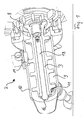
- the Fig. 1 shows a perspective schematic representation of the unit 2, in which the mixing shaft 1 according to the invention is installed.
- the mixing shaft will be described below.
- the mixing shaft 1 has at its one end another working tool 8, on which the entire shaft is supported.
- the steel core 3 has a fastening screw 16, with which the mixing shaft 1 is pressed against the working tool.
- In the walls 10 of the product unit 2 at least one injection nozzle 11 is arranged, are injected with the arbitrary means in the interior of the product unit 2.
- the mixing shaft 1 is driven with revolutions between 300 to 3,000 revolutions per minute.
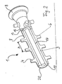
- the Fig. 2 shows a perspective view of a partial sectional view of the mixing shaft according to the invention 1.
- the mixing shaft 1 consists essentially of an elongated cylindrical steel core 3, which is surrounded by a plastic coating 6.
- the steel core 3 has a bore 17 in the center, in which a bolt 18 is guided with a thread, not shown here, with which the mixing shaft 1 is pressed with a screw 16 against the working tool.
- Both the surface of the flange and the entire cylindrical portion 7 of the steel core 3, with the exception of the end faces 19, are surrounded by a single plastic coating 6.
- the surface of the plastic coating 6 itself is structured and has, in the present exemplary embodiment, radially projecting mixing elements 4 whose distances (A) are different and are distributed over the entire surface circumference of the mixing shaft 1 quasi irregular.
- the coating 6 is in the present embodiment, a so-called PTFE (polytetrafluoroethylene), which is isostatic pressed at a relatively high pressure and sintered at temperatures between 360 ° C and 380 ° C. Because of the different coefficients of expansion of plastic and steel, air gaps are generally formed at the boundary surfaces 20 between the coating and the steel core, in which product residues penetrate and can no longer be removed.
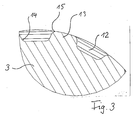
- the surface of the steel core 3 is executed structured.
- the structure of elongated grooves 12 and elongated protrusions 13 is formed over a part of the cylindrical portion of the steel core 3.
- the depth of the grooves is about 2 mm and the widths of the grooves 12 and the elevations are between 6 mm and 10 mm.
- the grooves 12 terminate shortly before the end face of the cylindrical portion 7 of the mixing shaft 1, whereby an additional slip resistance for the plastic coating 6 is given. Further, for some embodiments, it is advantageous to roughen the entire surface, with the exception of the end faces, of the cylindrical portion of the mixing shaft 1, whereby the plastic coating can penetrate into the pores of the roughening.
Landscapes
- Chemical & Material Sciences (AREA)
- Chemical Kinetics & Catalysis (AREA)
- Processing And Handling Of Plastics And Other Materials For Molding In General (AREA)
- Mixers Of The Rotary Stirring Type (AREA)
- Accessories For Mixers (AREA)
- Formation And Processing Of Food Products (AREA)
- Seeds, Soups, And Other Foods (AREA)
- Shafts, Cranks, Connecting Bars, And Related Bearings (AREA)
Priority Applications (1)
| Application Number | Priority Date | Filing Date | Title |
|---|---|---|---|
| PL04762574T PL1663465T3 (pl) | 2003-08-02 | 2004-08-02 | Mieszadło do mieszania i rozdrabniania artykułów spożywczych |
Applications Claiming Priority (2)
| Application Number | Priority Date | Filing Date | Title |
|---|---|---|---|
| DE10335552A DE10335552B4 (de) | 2003-08-02 | 2003-08-02 | Mischwelle zur Durchmischung und Zerteilung von Lebensmittelprodukten sowie Verfahren zur Herstellung eines Überzugs für eine derartige Mischwelle |
| PCT/DE2004/001729 WO2005014152A2 (de) | 2003-08-02 | 2004-08-02 | Mischwelle zur durchmischung und zerteilung von lebensmittelprodukten |
Publications (2)
| Publication Number | Publication Date |
|---|---|
| EP1663465A2 EP1663465A2 (de) | 2006-06-07 |
| EP1663465B1 true EP1663465B1 (de) | 2008-02-27 |
Family
ID=34129481
Family Applications (1)
| Application Number | Title | Priority Date | Filing Date |
|---|---|---|---|
| EP04762574A Expired - Lifetime EP1663465B1 (de) | 2003-08-02 | 2004-08-02 | Mischwelle zur durchmischung und zerteilung von lebensmittelprodukten |
Country Status (6)
| Country | Link |
|---|---|
| US (1) | US8833688B2 (pl) |
| EP (1) | EP1663465B1 (pl) |
| AT (1) | ATE387257T1 (pl) |
| DE (2) | DE10335552B4 (pl) |
| PL (1) | PL1663465T3 (pl) |
| WO (1) | WO2005014152A2 (pl) |
Families Citing this family (7)
| Publication number | Priority date | Publication date | Assignee | Title |
|---|---|---|---|---|
| DK1841327T3 (da) | 2005-01-28 | 2011-03-14 | Unilever Nv | Spiselige dispersioner indeholdende olie og strukturmiddel |
| DE102010023793A1 (de) | 2010-06-15 | 2011-12-15 | J. F. Knauer Industrie-Elektronik Gmbh | Vorrichtung und Verfahren zum Einmischen von Konditioniermittel, insbesondere Flockmittel, in Schlämme |
| KR101040927B1 (ko) | 2011-03-30 | 2011-06-16 | (주)플록마스터 | 슬러지 파쇄용 믹스장치 |
| CN103363813B (zh) * | 2013-06-20 | 2014-11-12 | 宁波长振铜业有限公司 | 具有自动捣料搅拌装置的熔炼装置 |
| WO2015142959A1 (en) * | 2014-03-17 | 2015-09-24 | Sani-Tech West, Inc. | Magnetic mixing system and method |
| US11103245B2 (en) * | 2018-12-31 | 2021-08-31 | Cilag Gmbh International | Knife for surgical stapler and associated method of manufacture with MIM and hip |
| DE102019125593A1 (de) * | 2019-09-24 | 2021-03-25 | Thomas Molé | Modular aufgebautes Mischwerkzeug |
Family Cites Families (18)
| Publication number | Priority date | Publication date | Assignee | Title |
|---|---|---|---|---|
| US2852238A (en) * | 1957-08-19 | 1958-09-16 | Toms River Cincinnati Chemical | Agitator for lined pressure vessel |
| DE1944828U (de) * | 1966-07-01 | 1966-08-25 | Ver Leichtmetallwerke Gmbh | Mischtrommel. |
| US3622129A (en) * | 1969-05-14 | 1971-11-23 | Bellco Glass Inc | Magnetic stirrer apparatus |
| DE8021396U1 (de) * | 1980-08-09 | 1980-12-04 | Bohlender, Hermann, 6970 Lauda | Ruehrwelle fuer ruehrwerke zur labormaessigen behandlung aggressiver medien |
| DE3332403A1 (de) * | 1983-09-08 | 1985-03-28 | Robert 5446 Engeln Wolff | Ruehrer als vorsatzgeraet fuer heimwerkermaschinen, z. b. bohrmaschinen, zum durchmischen von fluessigkeiten, suspensionen oder dgl. |
| US4651935A (en) * | 1984-10-19 | 1987-03-24 | Morehouse Industries, Inc. | Horizontal media mill |
| DE3723558A1 (de) * | 1987-07-16 | 1989-01-26 | Netzsch Erich Holding | Muehle, insbesondere ruehrwerksmuehle |
| DE8804492U1 (de) * | 1988-04-05 | 1988-07-07 | Polytetra Draack + Meyer Gmbh, 4050 Moenchengladbach | Rührer |
| DE9116859U1 (de) * | 1991-02-15 | 1994-04-07 | Stephan & Soehne | Vorrichtung zur Herstellung von Schmelzkäse |
| DE4208100C2 (de) * | 1992-03-13 | 1994-05-26 | Mtu Muenchen Gmbh | Rohling zur Herstellung von faserverstärkten Beschichtungen oder Metallbauteilen |
| DE4328160C2 (de) * | 1992-10-23 | 1994-10-20 | Reifenhaeuser Masch | Schneckenwelle einer Schneckenstrangpresse und Verfahren zur Herstellung einer solchen Schneckenwelle |
| CH688849A5 (de) * | 1993-02-25 | 1998-04-30 | Buehler Ag | Ruehrwerksmuehle. |
| DE19530026A1 (de) * | 1995-08-16 | 1997-02-20 | Werner & Pfleiderer | Schneckensatzelement für Schneckenmaschinen |
| DE19544871C2 (de) * | 1995-12-01 | 1998-02-26 | Hoechst Ag | Verfahren zur Herstellung und Aufarbeitung von fluorhaltigen organischen Verbindungen |
| DE69939784D1 (de) * | 1998-08-06 | 2008-12-04 | Eidgenoess Tech Hochschule | Schmelzverarbeitbares polytetrafluorethylen |
| JP4156807B2 (ja) * | 1999-06-01 | 2008-09-24 | エラン ファーマ インターナショナル,リミティド | 小型ミル及びその方法 |
| US6999432B2 (en) | 2000-07-13 | 2006-02-14 | Microsoft Corporation | Channel and quality of service adaptation for multimedia over wireless networks |
| WO2002009458A2 (en) | 2000-07-24 | 2002-01-31 | Bluesocket, Inc. | Method and system for enabling seamless roaming in a wireless network |
-
2003
- 2003-08-02 DE DE10335552A patent/DE10335552B4/de not_active Expired - Fee Related
-
2004
- 2004-08-02 US US10/567,133 patent/US8833688B2/en not_active Expired - Lifetime
- 2004-08-02 EP EP04762574A patent/EP1663465B1/de not_active Expired - Lifetime
- 2004-08-02 DE DE502004006334T patent/DE502004006334D1/de not_active Expired - Lifetime
- 2004-08-02 PL PL04762574T patent/PL1663465T3/pl unknown
- 2004-08-02 WO PCT/DE2004/001729 patent/WO2005014152A2/de not_active Ceased
- 2004-08-02 AT AT04762574T patent/ATE387257T1/de not_active IP Right Cessation
Also Published As
| Publication number | Publication date |
|---|---|
| DE502004006334D1 (de) | 2008-04-10 |
| WO2005014152A2 (de) | 2005-02-17 |
| ATE387257T1 (de) | 2008-03-15 |
| US8833688B2 (en) | 2014-09-16 |
| US20070125894A1 (en) | 2007-06-07 |
| DE10335552B4 (de) | 2005-07-28 |
| EP1663465A2 (de) | 2006-06-07 |
| WO2005014152A3 (de) | 2005-04-21 |
| DE10335552A1 (de) | 2005-03-17 |
| PL1663465T3 (pl) | 2008-10-31 |
Similar Documents
| Publication | Publication Date | Title |
|---|---|---|
| EP0615085B1 (de) | Verfahren zum Herstellen einer Wellenabdichtung | |
| DE3241926C2 (pl) | ||
| DE60202873T2 (de) | Verfahren zu herstellung eines stators für eine exzenterschneckenpumpe und sich daraus ergebender stator | |
| DE2234669A1 (de) | Duesenbaugruppe | |
| AT511880B1 (de) | Verschleissoptimierte herstellung von konischen spritzlöchern | |
| EP1663465B1 (de) | Mischwelle zur durchmischung und zerteilung von lebensmittelprodukten | |
| DE2460185A1 (de) | Verfahren zur herstellung von dichtungselementen mit hydrodynamischer wirkung | |
| WO2014166677A1 (de) | Mechanisches verbindungselement, zugehöriges verbindungssystem und zugehöriges oberflächenbehandlungsverfahren | |
| EP0165417B1 (de) | Kolbenring | |
| DE102017130039A1 (de) | Radialwellen-Dichtungsvorrichtung und Herstellungsverfahren | |
| DE3917925C2 (pl) | ||
| DE19730008C1 (de) | Panzerung für ein metallisches Triebwerksbauteil und Verfahren zu ihrer Herstellung | |
| DE3437559A1 (de) | Verfahren zur herstellung eines verschleissfesten arbeitsraumes, vorzugsweise fuer spritzgiessmaschinen und fuer ein- und zweiwellige extruder, auch konischer bauart, und ein nach diesem verfahren hergestellter verschleissfester arbeitsraum | |
| DE20312001U1 (de) | Mischwelle zur Durchmischung und Zerteilung von Lebensmittelprodukten | |
| DE2047631B2 (de) | Wellenlippendichtung | |
| EP1887264A1 (de) | Verfahren zum Herstellen eines tribologischen Bauteils | |
| DE3506668A1 (de) | Verschleisswiderstandserhoehende beschichtung am zylinder und an der schnecke einer kunststoff-schneckenpresse | |
| DE3448025C3 (de) | Verfahren zur Herstellung von Rotoren für Schraubenverdichter | |
| DE884437C (de) | Dichtung aus Stahl mit oberflaechengehaerteten, dichtenden Schneidkanten und Verfahren zum Herstellen solcher Dichtungen | |
| WO2005054522A1 (de) | Verfahren zum selektiven härten von dichtflächen | |
| DE9207833U1 (de) | Dichtungsvorrichtung | |
| EP3293432B1 (de) | Bauteil mit rohrabschnitt mit emailliertem bund | |
| DE19528483A1 (de) | Verfahren zur Herstellung von Schneidmessern für die Unterwassergranulierung | |
| DE10239379A1 (de) | Verfahren zur Bearbeitung eines Werkstücks für einen Kraftstoffhochdruckspeicher und Werkstück zur Anwendung des Verfahrens | |
| EP0765729B1 (de) | Teil-Schneckenwelle für eine Schneckenmaschine und Verfahren zu ihrer Herstellung |
Legal Events
| Date | Code | Title | Description |
|---|---|---|---|
| PUAI | Public reference made under article 153(3) epc to a published international application that has entered the european phase |
Free format text: ORIGINAL CODE: 0009012 |
|
| 17P | Request for examination filed |
Effective date: 20060228 |
|
| AK | Designated contracting states |
Kind code of ref document: A2 Designated state(s): AT BE BG CH CY CZ DE DK EE ES FI FR GB GR HU IE IT LI LU MC NL PL PT RO SE SI SK TR |
|
| GRAP | Despatch of communication of intention to grant a patent |
Free format text: ORIGINAL CODE: EPIDOSNIGR1 |
|
| DAX | Request for extension of the european patent (deleted) | ||
| GRAS | Grant fee paid |
Free format text: ORIGINAL CODE: EPIDOSNIGR3 |
|
| GRAA | (expected) grant |
Free format text: ORIGINAL CODE: 0009210 |
|
| AK | Designated contracting states |
Kind code of ref document: B1 Designated state(s): AT BE BG CH CY CZ DE DK EE ES FI FR GB GR HU IE IT LI LU MC NL PL PT RO SE SI SK TR |
|
| REG | Reference to a national code |
Ref country code: GB Ref legal event code: FG4D Free format text: NOT ENGLISH |
|
| REG | Reference to a national code |
Ref country code: CH Ref legal event code: EP |
|
| REG | Reference to a national code |
Ref country code: IE Ref legal event code: FG4D Free format text: LANGUAGE OF EP DOCUMENT: GERMAN |
|
| REF | Corresponds to: |
Ref document number: 502004006334 Country of ref document: DE Date of ref document: 20080410 Kind code of ref document: P |
|
| PG25 | Lapsed in a contracting state [announced via postgrant information from national office to epo] |
Ref country code: FI Free format text: LAPSE BECAUSE OF FAILURE TO SUBMIT A TRANSLATION OF THE DESCRIPTION OR TO PAY THE FEE WITHIN THE PRESCRIBED TIME-LIMIT Effective date: 20080227 Ref country code: ES Free format text: LAPSE BECAUSE OF FAILURE TO SUBMIT A TRANSLATION OF THE DESCRIPTION OR TO PAY THE FEE WITHIN THE PRESCRIBED TIME-LIMIT Effective date: 20080607 |
|
| PG25 | Lapsed in a contracting state [announced via postgrant information from national office to epo] |
Ref country code: SI Free format text: LAPSE BECAUSE OF FAILURE TO SUBMIT A TRANSLATION OF THE DESCRIPTION OR TO PAY THE FEE WITHIN THE PRESCRIBED TIME-LIMIT Effective date: 20080227 |
|
| REG | Reference to a national code |
Ref country code: IE Ref legal event code: FD4D |
|
| PG25 | Lapsed in a contracting state [announced via postgrant information from national office to epo] |
Ref country code: SK Free format text: LAPSE BECAUSE OF FAILURE TO SUBMIT A TRANSLATION OF THE DESCRIPTION OR TO PAY THE FEE WITHIN THE PRESCRIBED TIME-LIMIT Effective date: 20080227 Ref country code: SE Free format text: LAPSE BECAUSE OF FAILURE TO SUBMIT A TRANSLATION OF THE DESCRIPTION OR TO PAY THE FEE WITHIN THE PRESCRIBED TIME-LIMIT Effective date: 20080527 Ref country code: PT Free format text: LAPSE BECAUSE OF FAILURE TO SUBMIT A TRANSLATION OF THE DESCRIPTION OR TO PAY THE FEE WITHIN THE PRESCRIBED TIME-LIMIT Effective date: 20080721 Ref country code: IE Free format text: LAPSE BECAUSE OF FAILURE TO SUBMIT A TRANSLATION OF THE DESCRIPTION OR TO PAY THE FEE WITHIN THE PRESCRIBED TIME-LIMIT Effective date: 20080227 Ref country code: DK Free format text: LAPSE BECAUSE OF FAILURE TO SUBMIT A TRANSLATION OF THE DESCRIPTION OR TO PAY THE FEE WITHIN THE PRESCRIBED TIME-LIMIT Effective date: 20080227 Ref country code: CZ Free format text: LAPSE BECAUSE OF FAILURE TO SUBMIT A TRANSLATION OF THE DESCRIPTION OR TO PAY THE FEE WITHIN THE PRESCRIBED TIME-LIMIT Effective date: 20080227 |
|
| REG | Reference to a national code |
Ref country code: PL Ref legal event code: T3 |
|
| PG25 | Lapsed in a contracting state [announced via postgrant information from national office to epo] |
Ref country code: RO Free format text: LAPSE BECAUSE OF FAILURE TO SUBMIT A TRANSLATION OF THE DESCRIPTION OR TO PAY THE FEE WITHIN THE PRESCRIBED TIME-LIMIT Effective date: 20080227 |
|
| ET | Fr: translation filed | ||
| PLBE | No opposition filed within time limit |
Free format text: ORIGINAL CODE: 0009261 |
|
| STAA | Information on the status of an ep patent application or granted ep patent |
Free format text: STATUS: NO OPPOSITION FILED WITHIN TIME LIMIT |
|
| 26N | No opposition filed |
Effective date: 20081128 |
|
| PG25 | Lapsed in a contracting state [announced via postgrant information from national office to epo] |
Ref country code: MC Free format text: LAPSE BECAUSE OF NON-PAYMENT OF DUE FEES Effective date: 20080831 |
|
| REG | Reference to a national code |
Ref country code: CH Ref legal event code: PL |
|
| GBPC | Gb: european patent ceased through non-payment of renewal fee |
Effective date: 20080802 |
|
| PG25 | Lapsed in a contracting state [announced via postgrant information from national office to epo] |
Ref country code: EE Free format text: LAPSE BECAUSE OF FAILURE TO SUBMIT A TRANSLATION OF THE DESCRIPTION OR TO PAY THE FEE WITHIN THE PRESCRIBED TIME-LIMIT Effective date: 20080227 Ref country code: BG Free format text: LAPSE BECAUSE OF FAILURE TO SUBMIT A TRANSLATION OF THE DESCRIPTION OR TO PAY THE FEE WITHIN THE PRESCRIBED TIME-LIMIT Effective date: 20080527 |
|
| PG25 | Lapsed in a contracting state [announced via postgrant information from national office to epo] |
Ref country code: LI Free format text: LAPSE BECAUSE OF NON-PAYMENT OF DUE FEES Effective date: 20080831 Ref country code: CH Free format text: LAPSE BECAUSE OF NON-PAYMENT OF DUE FEES Effective date: 20080831 |
|
| PG25 | Lapsed in a contracting state [announced via postgrant information from national office to epo] |
Ref country code: CY Free format text: LAPSE BECAUSE OF FAILURE TO SUBMIT A TRANSLATION OF THE DESCRIPTION OR TO PAY THE FEE WITHIN THE PRESCRIBED TIME-LIMIT Effective date: 20080227 Ref country code: BE Free format text: LAPSE BECAUSE OF NON-PAYMENT OF DUE FEES Effective date: 20080831 |
|
| PG25 | Lapsed in a contracting state [announced via postgrant information from national office to epo] |
Ref country code: IT Free format text: LAPSE BECAUSE OF FAILURE TO SUBMIT A TRANSLATION OF THE DESCRIPTION OR TO PAY THE FEE WITHIN THE PRESCRIBED TIME-LIMIT Effective date: 20080227 |
|
| PG25 | Lapsed in a contracting state [announced via postgrant information from national office to epo] |
Ref country code: AT Free format text: LAPSE BECAUSE OF NON-PAYMENT OF DUE FEES Effective date: 20080802 |
|
| PG25 | Lapsed in a contracting state [announced via postgrant information from national office to epo] |
Ref country code: GB Free format text: LAPSE BECAUSE OF NON-PAYMENT OF DUE FEES Effective date: 20080802 |
|
| PG25 | Lapsed in a contracting state [announced via postgrant information from national office to epo] |
Ref country code: LU Free format text: LAPSE BECAUSE OF NON-PAYMENT OF DUE FEES Effective date: 20080802 Ref country code: HU Free format text: LAPSE BECAUSE OF FAILURE TO SUBMIT A TRANSLATION OF THE DESCRIPTION OR TO PAY THE FEE WITHIN THE PRESCRIBED TIME-LIMIT Effective date: 20080828 |
|
| PG25 | Lapsed in a contracting state [announced via postgrant information from national office to epo] |
Ref country code: GR Free format text: LAPSE BECAUSE OF FAILURE TO SUBMIT A TRANSLATION OF THE DESCRIPTION OR TO PAY THE FEE WITHIN THE PRESCRIBED TIME-LIMIT Effective date: 20080528 |
|
| REG | Reference to a national code |
Ref country code: FR Ref legal event code: ST Effective date: 20110729 |
|
| PG25 | Lapsed in a contracting state [announced via postgrant information from national office to epo] |
Ref country code: FR Free format text: LAPSE BECAUSE OF NON-PAYMENT OF DUE FEES Effective date: 20080901 |
|
| REG | Reference to a national code |
Ref country code: DE Ref legal event code: R082 Ref document number: 502004006334 Country of ref document: DE Representative=s name: REICHERT & LINDNER PARTNERSCHAFT PATENTANWAELT, DE |
|
| REG | Reference to a national code |
Ref country code: DE Ref legal event code: R082 Ref document number: 502004006334 Country of ref document: DE Representative=s name: REICHERT & LINDNER PARTNERSCHAFT PATENTANWAELT, DE Effective date: 20141217 Ref country code: DE Ref legal event code: R081 Ref document number: 502004006334 Country of ref document: DE Owner name: STEPHAN MACHINERY GMBH, DE Free format text: FORMER OWNER: STEPHAN MACHINERY GMBH & CO., 31789 HAMELN, DE Effective date: 20141217 |
|
| REG | Reference to a national code |
Ref country code: DE Ref legal event code: R079 Ref document number: 502004006334 Country of ref document: DE Free format text: PREVIOUS MAIN CLASS: B01F0015000000 Ipc: B01F0035000000 |
|
| PGFP | Annual fee paid to national office [announced via postgrant information from national office to epo] |
Ref country code: NL Payment date: 20220822 Year of fee payment: 19 |
|
| PGFP | Annual fee paid to national office [announced via postgrant information from national office to epo] |
Ref country code: TR Payment date: 20220729 Year of fee payment: 19 Ref country code: DE Payment date: 20220831 Year of fee payment: 19 |
|
| PGFP | Annual fee paid to national office [announced via postgrant information from national office to epo] |
Ref country code: PL Payment date: 20220725 Year of fee payment: 19 |
|
| REG | Reference to a national code |
Ref country code: DE Ref legal event code: R119 Ref document number: 502004006334 Country of ref document: DE |
|
| REG | Reference to a national code |
Ref country code: NL Ref legal event code: MM Effective date: 20230901 |
|
| PG25 | Lapsed in a contracting state [announced via postgrant information from national office to epo] |
Ref country code: NL Free format text: LAPSE BECAUSE OF NON-PAYMENT OF DUE FEES Effective date: 20230901 |
|
| PG25 | Lapsed in a contracting state [announced via postgrant information from national office to epo] |
Ref country code: NL Free format text: LAPSE BECAUSE OF NON-PAYMENT OF DUE FEES Effective date: 20230901 |
|
| PG25 | Lapsed in a contracting state [announced via postgrant information from national office to epo] |
Ref country code: DE Free format text: LAPSE BECAUSE OF NON-PAYMENT OF DUE FEES Effective date: 20240301 |
|
| PG25 | Lapsed in a contracting state [announced via postgrant information from national office to epo] |
Ref country code: PL Free format text: LAPSE BECAUSE OF NON-PAYMENT OF DUE FEES Effective date: 20230802 |
|
| PG25 | Lapsed in a contracting state [announced via postgrant information from national office to epo] |
Ref country code: PL Free format text: LAPSE BECAUSE OF NON-PAYMENT OF DUE FEES Effective date: 20230802 |