EP1661614A1 - Gehäuse - Google Patents
Gehäuse Download PDFInfo
- Publication number
- EP1661614A1 EP1661614A1 EP05109441A EP05109441A EP1661614A1 EP 1661614 A1 EP1661614 A1 EP 1661614A1 EP 05109441 A EP05109441 A EP 05109441A EP 05109441 A EP05109441 A EP 05109441A EP 1661614 A1 EP1661614 A1 EP 1661614A1
- Authority
- EP
- European Patent Office
- Prior art keywords
- housing part
- housing
- opening
- torque
- locking means
- Prior art date
- Legal status (The legal status is an assumption and is not a legal conclusion. Google has not performed a legal analysis and makes no representation as to the accuracy of the status listed.)
- Granted
Links
Images

Classifications
-
- B—PERFORMING OPERATIONS; TRANSPORTING
- B01—PHYSICAL OR CHEMICAL PROCESSES OR APPARATUS IN GENERAL
- B01D—SEPARATION
- B01D46/00—Filters or filtering processes specially modified for separating dispersed particles from gases or vapours
- B01D46/0039—Filters or filtering processes specially modified for separating dispersed particles from gases or vapours with flow guiding by feed or discharge devices
- B01D46/0041—Filters or filtering processes specially modified for separating dispersed particles from gases or vapours with flow guiding by feed or discharge devices for feeding
- B01D46/0046—Filters or filtering processes specially modified for separating dispersed particles from gases or vapours with flow guiding by feed or discharge devices for feeding provoking a tangential stream
-
- B—PERFORMING OPERATIONS; TRANSPORTING
- B01—PHYSICAL OR CHEMICAL PROCESSES OR APPARATUS IN GENERAL
- B01D—SEPARATION
- B01D46/00—Filters or filtering processes specially modified for separating dispersed particles from gases or vapours
- B01D46/0001—Making filtering elements
-
- F—MECHANICAL ENGINEERING; LIGHTING; HEATING; WEAPONS; BLASTING
- F02—COMBUSTION ENGINES; HOT-GAS OR COMBUSTION-PRODUCT ENGINE PLANTS
- F02M—SUPPLYING COMBUSTION ENGINES IN GENERAL WITH COMBUSTIBLE MIXTURES OR CONSTITUENTS THEREOF
- F02M35/00—Combustion-air cleaners, air intakes, intake silencers, or induction systems specially adapted for, or arranged on, internal-combustion engines
- F02M35/02—Air cleaners
- F02M35/0201—Housings; Casings; Frame constructions; Lids; Manufacturing or assembling thereof
- F02M35/0202—Manufacturing or assembling; Materials for air cleaner housings
- F02M35/0203—Manufacturing or assembling; Materials for air cleaner housings by using clamps, catches, locks or the like, e.g. for disposable plug-in filter cartridges
-
- B—PERFORMING OPERATIONS; TRANSPORTING
- B01—PHYSICAL OR CHEMICAL PROCESSES OR APPARATUS IN GENERAL
- B01D—SEPARATION
- B01D2201/00—Details relating to filtering apparatus
- B01D2201/40—Special measures for connecting different parts of the filter
- B01D2201/4015—Bayonet connecting means
-
- B—PERFORMING OPERATIONS; TRANSPORTING
- B01—PHYSICAL OR CHEMICAL PROCESSES OR APPARATUS IN GENERAL
- B01D—SEPARATION
- B01D2265/00—Casings, housings or mounting for filters specially adapted for separating dispersed particles from gases or vapours
- B01D2265/02—Non-permanent measures for connecting different parts of the filter
- B01D2265/022—Bayonet connecting means
Definitions
- the invention relates to a housing, in particular filter housing, preferably air filter housing according to the preamble of patent claim 1.
- bayonet locks are usually characterized by latching planes on a housing part and locking cams on the housing part to be connected thereto. To connect these two housing halves the locking cams and the locking planes are arranged in pairs. Depending on the size and the diameter of the housing, two to eight corresponding locking pairs have been proven. Depending on the housing shape, these are arranged radially one after the other or opposite one another. Inside the housing normally hollow cylindrical, radially flowed through filter elements or cylindrical, axially flowed through filter elements are used. In case of maintenance, it is necessary to change these elements, the housing must be designed so separable that this change is easily possible.
- the bayonet lock described above offers the possibility of simple and tool-free maintenance.
- WO 99/14483 A1 describes various embodiments of a bayonet closure for connecting hollow cylindrical air filter housing parts.
- a hollow cylindrical cover part is connected via the bayonet connection with a hollow cylindrical lower housing part.
- the cover part has the corresponding latching elements in the region of the cylindrical connection opening on the inner peripheral circumferential surface.
- the lower housing part in the region of the cylindrical connection opening on the respective latching elements on the outer peripheral circumferential surface.
- the locking planes have an L-shape on, wherein one of the legs is arranged parallel to the rotational movement during closing and the other leg perpendicular thereto.
- the corresponding locking cam on the other housing part is formed in the form of a U's.
- the latching plane is designed in the form of a P and the associated locking cam has a kind of banana shape.
- always the same locking pairings are used.
- Each mating pair assumes the functions of torque adjustment of closing and opening, adjusting the holding force and adjustment of the radial and axial play in the closed state.
- the vote is to be assessed as problematic in the known in the prior art solution.
- the parameters to be matched are combined in the respective locking pairs, so that when changing a function, one or more functions are likewise changed.
- the functions here are torque when closing, torque when opening, locking force in the axial direction, locking force in the radial direction, play in the axial direction and play in the radial direction. Due to the disadvantage that when changing a function one or more functions are also changed the tuning is much more difficult because not any combination is possible and always a compromise must be found.
- the object of the invention is therefore to find a simple bayonet system for connecting two housing halves, which can be both easily tuned and ensures easy handling. Furthermore, it should be easy and inexpensive to manufacture.
- the invention relates to a housing, in particular filter housing, preferably air filter housing, which has at least two hollow cylindrical housing parts.
- a first and a second housing part via a rotational relative rotational movement are releasably connected to each other, wherein on the housing parts each mutually corresponding latching means are arranged.
- a number of locking means in the region of the junction of the two hollow cylindrical housing parts are arranged on the outer circumference of the first housing part and a corresponding number of locking means on the inner circumference in the region of the connection point of the second housing part.
- the first housing part has a slightly smaller diameter than the second housing part in the region of the connection point, so that when connecting the two housing parts with each other, the second housing part can be pushed over a certain axial length over the first housing part.
- the first housing part has an axial stop for the second housing part, so that upon reaching the axial stop and the subsequent rotational rotation of the two housing parts to each other a releasable connection is made via the locking means.
- the stop point forms an abutment for the locking means which correspond with one another.
- a first number of locking means comprises means for holding the connection between the housing parts and a second number of locking means means for adjusting the torque for opening and means for adjusting the torque for closing the housing.
- the means for holding the connection determine the locking forces in the axial direction and the axial play and the radial clearance and the means for adjusting the torque the respectively necessary torques for opening and closing the connection and the locking force in the radial direction.
- the number of locking means is to be set so that the required forces and torques can be applied and adapted to the material.
- the housing parts are produced in the molding process in particular injection molding. This makes the bayonet lock very cheap to manufacture.
- the closure can be imaged directly in the tool halves.
- the first number of latching means has mutually corresponding holding planes arranged parallel to the rotary direction of rotation for receiving the axial clamping force and determining the axial clearance. Furthermore, the first number of latching means arranged perpendicular to the rotational direction of rotation retaining planes for determining the radial clearance.
- the effective length of the holding planes arranged parallel to the rotational direction of rotation depends on the maximum clamping force. The higher the maximum clamping force, the longer the effective length of the parallel planes should be.
- the latching means of the first housing part and the latching means of the second housing part the corresponding to each other executed parallel planes, wherein the end stop on the housing part acts as an abutment.
- a locking means of a housing part is received by a vertically arranged holding plane of the other housing part in the end position during closing.
- the second number of locking means with each other corresponding parallel to the rotational direction of rotation arranged planes on the one hand and at an acute angle to these levels of torque levels on the other hand.
- the latching means arranged on a first housing part have, on their side facing the housing part opening, a dome pointing in the direction of the opening. From this crest, impact planes on both sides of the crest drop toward the other end of the first housing part. This has the meaning that when a joining of the two housing parts, the locking means of a second housing part when hitting the latching means of the first housing part slide off at their crests and or their Auf Economicsebenen and so allow an assembly.
- a first housing part which is necessary for the above-mentioned housing, has at least two identically configured first latching means in the region of the connection to the second housing part, such that the first latching means cooperate with corresponding second latching means of the second housing part.
- the latching means arranged on the first housing part are preferably arranged uniformly on the circumference of the housing in the region of the connection point and all have the same shape. Therefore, it makes sense to carry out at different sized housing parts, the first housing part as the larger of the two housing parts. Should it be due to changed requirements to change certain factors in connection with the connection of the housing parts such. As holding forces, torque forces or play, it is cheaper to modify the injection mold for the smaller housing part so in this example, the second housing part.
- the identically configured first locking means have a plane substantially parallel to the direction of rotation with an active surface which faces in the direction opposite to the opening.
- the parallel plane and the perpendicular planes to be formed integrally form an inside open U-shape.
- the U-shape results from the manufacturing point of view in the injection molding process, an accumulation of material by an example, massive contour without forming a cavity within the U's.
- the interior of the triangle is recessed in order to avoid again accumulation of material.
- this embodiment would be more expensive by additionally required slider in the injection mold.
- the second housing part for an above-mentioned housing has at least two differently configured second latching means in the region of the connection to the first housing, such that the one embodiment of the second latching means in conjunction with the first latching means of the first housing part assume holding functions and the second embodiment of the second latching means take over in connection with the first locking means of the first housing part torque setting functions for opening and closing.
- identically configured locking means of the first housing part with at least two different embodiments of locking means of the second housing part on the one hand cause a tuning of the connection system and on the other hand offer a cheap and easy production possibility.
- By separating holding and torque functions by means of different embodiments of the latching means of the second housing part it is possible to change individual functions without having direct influence on other functions.
- a first embodiment of the latching means of the housing has a parallel to the rotary direction of rotation arranged, in the direction of the open side of the housing part opposite side, facing holding plane with an active surface for receiving the axial clamping force and determination of the axial clearance, as well a perpendicular thereto, with its free end in the opposite direction of the housing part opening facing, arranged holding plane with an active surface for adjusting the radial clearance and as an end stop when closing.
- the locking means has approximately the shape of a horizontal L's, wherein the longer side is arranged parallel to the direction of rotation and the leg of the L's perpendicular to the direction of the housing part opening opposite direction.
- the holding plane arranged parallel to the direction of rotation with its active surface on the side opposite the housing opening corresponds to an active surface of a likewise parallel holding plane of the latching means of the first housing part.
- the Active surfaces are mutually supported by the abutment is formed by the stop of the two housing parts to each other.
- the second embodiment of the locking means of the second housing part standing at an acute angle to the rotational direction of rotation, extending from a dome have torque levels, which have effective surfaces on the opening of the housing part opposite side.
- the angles for determining the torque when closing are approximately between zero and sixty degrees, preferably between five and thirty degrees to the plane parallel to the direction of rotation.
- the angles for determining the torque to open the connection are in a range of about zero to eighty degrees, preferably ten to sixty degrees.
- the axial distance between the dome tip and the end point of the locking means of the first housing part in the closed state determines the locking force of the connection in the radial direction.
- both embodiments of the latching means arranged on the second housing part have, on their side facing the housing part opening, a dome pointing in the direction of the opening. From this crest incident planes fall off on both sides of the crest toward the other end of the second housing part.
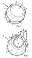
- FIG. 1 shows a first housing part according to the invention in a schematic view
- FIG. 2 shows a second housing part according to the invention, likewise in a schematic view
- Figure 3 shows a first embodiment consisting of locking plane and locking cams
- Figure 4 shows a second embodiment of the connection between locking cam and locking plane.
- FIG. 1 shows a cup-shaped first housing part 10 which is essentially hollow-cylindrical in shape and has a cylindrical opening.
- an inner circumferential surface 11 is formed by a shoulder edge 12 in the first housing part 10.
- the diameter of the first housing part 10 makes in the region of the shoulder edge 12 a diameter jump to a larger one Diameter in the area of the opening.
- two different configurations of locking means 13, 14 are arranged at regular intervals.
- the outer surface of the first housing part 10 has in the region of the opening handle cam 15 for handling the first housing part.
- the first housing part is produced in the primary molding process, in particular injection molding process.
- FIG. 2 shows a second likewise substantially pot-shaped cylindrical housing part 16 with an inlet 17 which is arranged tangentially at one end of the second housing part 16 through a connecting piece 18.
- an outlet 19 is arranged concentrically on the end face of the second housing part 16, wherein the outlet 19 has Klipsnasen 20 for sealingly receiving an outlet nozzle, not shown here.
- On the opposite side of the second housing part 16 is caused by a stop edge 21, a diameter jump, whereby the diameter of the housing in the region of an opening 24 which is disposed opposite to the outlet 19, is less than on the opposite side of the opening 24.
- an outer lateral surface 22 is formed at the corresponding distance to the latching planes 13, 14 of the first figure locking cam 23 are arranged.
- the locking cam 23 has a parallel to the direction of rotation of the two housing halves 10, 16 lying active surface 25 and two peaks 26 which over 27 surfaces the active surface 25 are connected.
- the shape of the detent cam 23 is similar to an open U, the shape being such was chosen to avoid accumulation of material. Other forms are also conceivable, wherein the active surface 25 and the surfaces 27 arranged perpendicular thereto must be maintained.
- the locking cams 23, which are arranged in the second housing part 16, are positioned there in such a way that the opening of the U points in the direction of the opening 24.
- the first embodiment of the latching plane 13 of the first housing part 10 also has an active surface 28, which is also parallel to the direction of rotation of the two housing halves 10, 16 to each other, as the active surface 25 of the locking cam 23.
- Active surface 29 is provided, which corresponds to one of the surfaces 27 of the locking cam 23 and thus forms a radial end stop.
- the locking plane 13 has an obliquely arranged to the effective surface 28 impact plane 30 which opens at its highest points in a crest 31.
- the overall shape of the detent plane 13 is roughly comparable to a horizontal L, with the active surface 28 and the short leg of the L's pointing in the direction of the closed first housing part 10.
- the locking cam 23 and the first locking plane 13 are in the connected state of the two housing parts 10, 16 via a holding plane 32 and a Radialab gleichebene 33 in contact.
- the holding plane 32 determines the locking forces in the axial direction and the axial clearance and the radial plane 33 determines the radial clearance.
- the second detent plane 14 in this case has an effective surface 34 which is arranged at an angle ⁇ 2 to the plane of rotation and which transmits the torque during the Closing the connection determines and another active surface 35 which is arranged at an angle ⁇ 1 to the rotation plane and determines the torque when opening the connection on.
- the height difference a between the intersection of the active surfaces 34 and 35 and the active surface 25 of the locking cam 23 determines the locking force of the connection in the radial direction.
- the angle ⁇ 2 determines the torque to close the connection, which is between zero and sixty degrees, preferably between five and thirty degrees.
Landscapes
- Engineering & Computer Science (AREA)
- Chemical & Material Sciences (AREA)
- Chemical Kinetics & Catalysis (AREA)
- Manufacturing & Machinery (AREA)
- General Engineering & Computer Science (AREA)
- Mechanical Engineering (AREA)
- Combustion & Propulsion (AREA)
- Quick-Acting Or Multi-Walled Pipe Joints (AREA)
- Lock And Its Accessories (AREA)
- Snaps, Bayonet Connections, Set Pins, And Snap Rings (AREA)
- Filtering Of Dispersed Particles In Gases (AREA)
- Clamps And Clips (AREA)
- Pivots And Pivotal Connections (AREA)
- Glass Compositions (AREA)
Abstract
Description
- Die Erfindung betrifft ein Gehäuse, insbesondere Filtergehäuse, vorzugsweise Luftfiltergehäuse nach dem Oberbegriff des Patentanspruchs 1.
- Im Stand der Technik sind hohlzylindrische Luftfiltergehäuse mit Bajonettverschlüssen bekannt. Derartige Bajonettverschlüsse zeichnen sich in der Regel durch Rastebenen an einem Gehäuseteil und Rastnocken am damit zu verbindenden Gehäuseteil aus. Zum Verbinden dieser beiden Gehäusehälften werden die Rastnocken und die Rastebenen paarweise angeordnet. In Abhängigkeit der Größe und des Durchmessers des Gehäuses haben sich zwei bis acht miteinander korrespondierende Rastpaare bewährt. Je nach Gehäuseform werden diese radial nacheinander oder gegenüberliegend angeordnet. Im Inneren der Gehäuse werden normalerweise hohlzylindrische, radialdurchströmte Filterelemente oder zylindrische, axial durchströmte Filterelemente verwendet. Im Wartungsfall ist es notwendig diese Elemente zu wechseln, wobei die Gehäuse derart trennbar ausgelegt sein müssen, dass dieser Wechsel problemlos möglich ist. Der oben beschriebene Bajonettverschluss bietet hier die Möglichkeit einer einfachen und werkzeuglosen Wartung.
- Die WO 99/14483 A1 beschreibt verschiedene Ausführungsformen eines Bajonettverschlusses zur Verbindung von hohlzylindrischen Luftfiltergehäuseteilen. Hierbei wird ein hohlzylindrisches Deckelteil über die Bajonettverbindung mit einem hohlzylindrischen unterem Gehäuseteil verbunden. Das Deckelteil weist hierzu im Bereich der zylindrischen Verbindungsöffnung an der innen liegenden umlaufenden Mantelfläche die entsprechenden Rastelemente auf. Dahingegen weist das untere Gehäuseteil im Bereich der zylindrischen Verbindungsöffnung die jeweiligen Rastelemente an der außen liegenden umlaufenden Mantelfläche auf. In einer Ausgestaltung weisen die Rastebenen eine L-Form auf, wobei einer der Schenkel parallel zur Drehbewegung beim Verschließen und der andere Schenkel senkrecht dazu angeordnet ist. Der hierzu korrespondierende Rastnocken auf dem anderen Gehäuseteil ist in Form eines U's ausgeformt. Gemäß einer weiteren Ausführungsform ist die Rastebene in Form eines P's gestaltet und der dazugehörige Rastnocken weist eine Art Bananenform auf. Der jeweils senkrecht zur Rotationsverschließ- oder Öffnungsbewegung ausgestaltete Teil der Rastebene sei es bei der L-förmigen oder bei der P-förmigen Ausgestaltung wirkt hierbei als Anschlag. In beiden Ausführungsformen werden immer dieselben Rastpaarungen verwendet. Dabei übernimmt jede Rastpaarung die Funktionen Drehmomenteinstellung des Verschließens und Öffnens, Einstellen der Haltekraft und Einstellung des radialen und axialen Spiels im verschlossenen Zustand.
- Neben den bekannten Vorteilen wie beispielsweise niedrige Kosten, einfache Handhabung und hohe Integration entstehen trotzdem einige Nachteile hierbei. Insbesondere die Abstimmung ist bei der im Stand der Technik bekannten Lösung als problematisch zu bewerten. Bei den oben beschriebenen Bajonettlösungen sind die abzustimmenden Parameter in den jeweiligen Rastpaaren kombiniert, so dass beim Ändern einer Funktion eine oder mehrere Funktionen ebenfalls geändert werden. Die Funktionen sind hierbei Drehmoment beim Schließen, Drehmoment beim Öffnen, Zuhaltekraft in axialer Richtung, Zuhaltekraft in radialer Richtung, Spiel in axialer Richtung und Spiel in radialer Richtung. Durch den Nachteil das beim Ändern einer Funktion eine oder mehrere Funktionen ebenfalls geändert werden wird das Abstimmen wesentlich erschwert, da nicht jede beliebige Kombination möglich ist und stets ein Kompromiss gefunden werden muss.
- Die Aufgabe der Erfindung ist es daher ein möglichst einfaches Bajonettsystem zum Verbinden zweier Gehäusehälften zu finden, welches sich sowohl einfach abstimmen lässt als auch eine einfache Handhabung gewährleistet. Weiterhin sollte es einfach und kostengünstig in der Herstellung sein.
- Diese Aufgabe wird durch die Merkmale des Patentanspruches 1 gelöst.
- Die Erfindung betrifft ein Gehäuse, insbesondere Filtergehäuse, vorzugsweise Luftfiltergehäuse, welches wenigstens zwei hohlzylindrische Gehäuseteile aufweist. Dabei sind ein erstes und ein zweites Gehäuseteil über eine rotative Relativdrehbewegung zueinander lösbar verbindbar, wobei an den Gehäuseteilen jeweils zueinander korrespondierende Rastmittel angeordnet sind. Dabei sind eine Anzahl von Rastmitteln im Bereich der Verbindungsstelle der beiden hohlzylindrischen Gehäuseteile am Außenumfang des ersten Gehäuseteils angeordnet und eine dazu korrespondierende Anzahl von Rastmitteln am Innenumfang im Bereich der Verbindungsstelle des zweiten Gehäuseteils angeordnet. Das erste Gehäuseteil weist einen geringfügig kleineren Durchmesser als das zweite Gehäuseteil im Bereich der Verbindungsstelle auf, so dass beim Verbinden der beiden Gehäuseteilen miteinander das zweite Gehäuseteil über eine gewisse axiale Länge über das erste Gehäuseteil geschoben werden kann. Hierbei weist das erste Gehäuseteil einen axialen Anschlag für das zweite Gehäuseteil auf, so dass bei Erreichen des axialen Anschlags und darauf folgender rotativer Verdrehung der beiden Gehäuseteile zueinander eine lösbare Verbindung über die Rastmittel hergestellt wird. Hierbei bildet die Anschlagstelle ein Gegenlager für die miteinander korrespondieren Rastmittel. Erfindungsgemäß weist eine erste Anzahl von Rastmitteln Mittel zum Halten der Verbindung zwischen den Gehäuseteilen auf und eine zweite Anzahl von Rastmitteln Mittel zur Einstellung des Drehmoments zum Öffnen und Mittel zur Einstellung des Drehmoments zum Schließen des Gehäuses. Dabei bestimmen bevorzugt die Mittel zum Halten der Verbindung die Zuhaltekräfte in axialer Richtung und das axiale Spiel sowie das radiale Spiel und die Mittel zur Einstellung des Drehmoments die jeweils notwendigen Drehmomente zum Öffnen und Schließen der Verbindung sowie die Zuhaltekraft in radialer Richtung. In Abhängigkeit der Größe und des Durchmessers der Gehäuseteile ist die Anzahl der Rastmittel derart festzulegen, dass die benötigten Kräfte und Drehmomente aufgebracht werden können und dem Material angepasst sind. Durch diese Trennung verschiedener Funktionen in zwei verschiedene Ausgestaltungen von Rastmitteln ergibt sich eine sehr gute Abstimmbarkeit des Systems gegenüber den bekannten Bajonettverschlüssen. Jede der nachfolgenden Funktionen kann dabei einzeln abgestimmt werden:
- - Drehmoment beim Schließen
- - Drehmoment beim Öffnen
- - Zuhaltekraft in axialer Richtung
- - Zuhaltekraft in radialer Richtung
- - Spiel in axialer Richtung
- - Spiel in radialer Richtung.
- Trotz dieser guten Möglichkeiten der Abstimmbarkeit des Systems wird weiterhin eine einfache Herstellbarkeit gewährleistet und es müssen keine Abschläge bei der Bedienung oder der Robustheit des Gesamtsystems in Kauf genommen werden. Erreicht wird dies durch wenigstens zwei unterschiedliche Paarungen von Rastnocken und Rastebenen welche korrespondierend zueinander einmal außen am Umfang und einmal innen am Umfang im Bereich der Verbindung der beiden Gehäuseteile angeordnet sind.
- Gemäß einer vorteilhaften Ausgestaltung der Erfindung sind die Gehäuseteile im Urformverfahren insbesondere Spritzgießverfahren hergestellt. Dadurch ist der Bajonettverschluss sehr günstig herzustellen. Der Verschluss kann direkt in den Werkzeughälften abgebildet werden.
- Es ist vorteilhaft, wenn die erste Anzahl von Rastmitteln miteinander korrespondierende jeweils parallel zur rotativen Verdrehrichtung angeordnete Halteebenen zur Aufnahme der axialen Zuhaltekraft und Bestimmung des axialen Spiels aufweist. Weiterhin weist die erste Anzahl von Rastmitteln senkrecht zur rotativen Verdrehrichtung angeordnete Halteebenen zur Bestimmung des radialen Spiels auf. Die wirksame Länge der parallel zur rotativen Verdrehrichtung angeordneten Halteebenen hängt hierbei von der maximalen Zuhaltekraft ab. Je höher die maximale Zuhaltekraft ist desto länger sollte die wirksame Länge der parallel angeordneten Ebenen sein. Hierbei weisen die Rastmittel des ersten Gehäuseteils sowie die Rastmittel des zweiten Gehäuseteils die korrespondierend zueinander ausgeführten parallelen Ebenen auf, wobei der Endanschlag am Gehäuseteil als Gegenlager fungiert. Durch die senkrecht zur rotativen Verdrehrichtung angeordneten Halteebenen lässt sich das radiale Spiel einstellen. Hierbei wird ein Rastmittel des einen Gehäuseteils von einer senkrecht angeordneten Halteebene des anderen Gehäuseteils in der Endposition beim Verschließen aufgenommen.
- Gemäß einer vorteilhaften Ausgestaltung der Erfindung weist die zweite Anzahl von Rastmitteln miteinander korrespondierende parallel zur rotativen Verdrehrichtung angeordnete Ebenen einerseits und unter einem spitzen Winkel zu diesen Ebenen stehende Drehmomentebenen andererseits auf. Durch die Wahl der jeweiligen Winkel der Drehmomentebenen lässt sich das Drehmoment zum Öffnen der Verbindung unabhängig vom Drehmoment zum Schließen der Verbindung einstellen. Durch die Variation der Steigung der beiden Drehmomentebenen lässt sich jeweils ein höheres oder ein niedrigeres Drehmoment zum Öffnen oder Schließen vorgeben.
- Es ist weiterhin vorteilhaft, wenn die an einem ersten Gehäuseteil angeordneten Rastmittel an ihrer der Gehäuseteilöffnung zugewandten Seite eine in Richtung der Öffnung weisende Kuppe aufweisen. Von dieser Kuppe fallen Auftreffebenen zu beiden Seiten der Kuppe in Richtung des anderen Endes des ersten Gehäuseteils ab. Dies hat den Sinn, dass bei einem Zusammenfügen der beiden Gehäuseteile die Rastmittel eines zweiten Gehäuseteils beim Auftreffen auf die Rastmittel des ersten Gehäuseteils an deren Kuppen und oder deren Auftreffebenen abgleiten und so ein Zusammenfügen zu ermöglichen. Dies hat den Vorteil, dass die beiden Gehäuseteile in jedweder Position zueinander zum Verschließen ineinander gesetzt werden können, entweder wird eine Position getroffen bei der die Rastmittel aneinander berührungslos vorbeigehen und dann beim Verdrehen einrasten oder die Rastmittel treffen im ersten Schritt aufeinander und gleiten durch die Kuppen und die damit verbundenen Auftreffebenen leicht und einfach aufeinander ab bis zu einer Position bei der ein verbinden der Gehäuseteile durch verdrehen möglich ist.
- Ein für das oben genannte Gehäuse notwendiges erstes Gehäuseteil weist im Bereich der Verbindungsstelle zum zweiten Gehäuseteil wenigstens zwei gleich ausgestaltete erste Rastmittel auf, derart dass die ersten Rastmittel mit korrespondierenden zweiten Rastmitteln des zweiten Gehäuseteils zusammen wirken. Die am ersten Gehäuseteil angeordneten Rastmittel sind bevorzugt gleichmäßig am Umfang des Gehäuses im Bereich der Verbindungsstelle angeordnet und weisen alle die gleiche Form auf. Daher bietet es sich an, bei unterschiedlich großen Gehäuseteilen das erste Gehäuseteil als das größere der beiden Gehäuseteile auszuführen. Sollte es durch geänderte Anforderungen zu einer Änderung bestimmter Faktoren im Zusammenhang mit der Verbindung der Gehäuseteile wie z. B. Haltekräfte, Drehmomentkräfte oder Spiel kommen, ist es günstiger das Spritzgießwerkzeug für das kleinere Gehäuseteil also in diesem Beispiel das zweite Gehäuseteil zu modifizieren.
- Gemäß einer vorteilhaften Ausgestaltung des ersten Gehäuseteils weisen die gleich ausgestalteten ersten Rastmittel eine im Wesentlichen zur Verdrehrichtung parallele Ebene mit einer Wirkfläche welche in die der Öffnung entgegen gesetzte Richtung weist auf. Jeweils an den Enden der parallelen Ebene sind einstückig damit verbundene im Wesentlichen senkrecht dazu verlaufende Ebenen angeordnet. Die freien Enden dieser zwei senkrecht verlaufenden Ebenen weisen in die der Gehäuseteilöffnung gegenüberliegende Richtung. Dadurch bilden die parallele Ebene und die senkrecht dazustehenden Ebenen einstückig eine innen geöffnete U-Form. Die U-Form ergibt sich aus fertigungstechnischer Hinsicht im Spritzgießverfahren, um eine Materialanhäufung durch eine beispielsweise massive Kontur ohne Ausbildung eines Hohlraums innerhalb des U's. Es ist jedoch auch denkbar unter Beibehaltung der parallelen Ebene eine Dreiecksform zu verwenden, wobei das Innere des Dreiecks ausgespart ist um wiederum eine Materialanhäufung zu vermeiden. Diese Ausführung wäre allerdings durch zusätzlich benötigte Schieber im Spritzgießwerkzeug aufwendiger.
- Das zweite Gehäuseteil für ein oben genanntes Gehäuse weist im Bereich der Verbindungsstelle zum ersten Gehäuse wenigstens zwei unterschiedlich ausgestaltete zweite Rastmittel auf, derart dass die eine Ausgestaltung der zweiten Rastmittel in Verbindung mit den ersten Rastmitteln des ersten Gehäuseteils Haltefunktionen übernehmen und die zweite Ausgestaltung der zweiten Rastmittel in Verbindung mit den ersten Rastmitteln des ersten Gehäuseteils Drehmomenteinstellungsfunktionen zum Öffnen und Schließen übernehmen. Hier wird deutlich, dass gleich gestaltete Rastmittel des ersten Gehäuseteils mit wenigstens zwei unterschiedlichen Ausgestaltungen von Rastmitteln des zweiten Gehäuseteils einerseits eine Abstimmbarkeit des Verbindungssystems bewirken und andererseits eine günstige und einfache Herstellungsmöglichkeit bieten. Durch das Trennen von Halte- und Drehmomentfunktionen durch unterschiedliche Ausgestaltungen der Rastmittel des zweiten Gehäuseteils besteht die Möglichkeit, Einzelfunktionen zu ändern ohne damit direkten Einfluss auf andere Funktionen zu nehmen.
- Gemäß einer vorteilhaften Ausgestaltung des zweiten Gehäuseteils weist eine erste Ausgestaltung der Rastmittel des Gehäuses eine parallel zur rotativen Verdrehrichtung angeordnete, in Richtung der der geöffneten Seite des Gehäuseteils gegenüberliegenden Seite, zugewandte Halteebene mit einer Wirkfläche zur Aufnahme der axialen Zuhaltekraft und Bestimmung des axialen Spiels, sowie eine senkrecht dazu, mit ihrem freien Ende in entgegengesetzter Richtung der Gehäuseteilöffnung weisende, angeordnete Halteebene mit einer Wirkfläche zur Einstellung des radialen Spiels und als Endanschlag beim Verschließen auf. Das Rastmittel weist dabei in etwa die Form eines liegenden L's auf, wobei die längere Seite parallel zur Verdrehrichtung angeordnet ist und der Schenkel des L's senkrecht dazu in die der Gehäuseteilöffnung entgegen gesetzte Richtung weist. Die parallel zur Verdrehrichtung angeordnete Halteebene mit ihrer Wirkfläche auf der der Gehäuseöffnung gegenüberliegenden Seite korrespondiert mit einer Wirkfläche einer ebenso parallelen Halteebene der Rastmittel des ersten Gehäuseteils. Die Wirkflächen stützen sich dabei gegenseitig ab wobei das Gegenlager hierzu durch den Anschlag der beiden Gehäuseteile zueinander gebildet wird. Im Gegensatz dazu bewirkt die senkrecht dazu angeordnete Halteebene mit ihrer Wirkfläche einen Endanschlag wobei durch eine Verlegung der senkrechten Halteebene das radiale Spiel eingestellt werden kann.
- Es ist vorteilhaft wenn die zweite Ausgestaltung der Rastmittel des zweiten Gehäuseteils unter einem spitzen Winkel zur rotativen Verdrehrichtung stehende, sich von einer Kuppe erstreckende, Drehmomentebenen aufweisen, welche Wirkflächen auf der der Öffnung des Gehäuseteils entgegengesetzten Seite aufweisen. Durch die Wahl der jeweiligen Winkel zur Ebene parallel zur Verdrehebene lässt sich das Drehmoment zum Öffnen der Verbindung unabhängig vom Drehmoment zum Schließen der Verbindung einstellen. Die Winkel zur Bestimmung des Drehmoments beim Schließen liegen in etwa zwischen null und sechzig Grad, bevorzugt zwischen fünf und dreißig Grad zur Ebene parallel zur Verdrehrichtung. Die Winkel zur Bestimmung des Drehmoments zum Öffnen der Verbindung liegen in einem Bereich etwa von null bis achtzig Grad bevorzugt von zehn bis sechzig Grad. Die axiale Distanz zwischen der Kuppenspitze und dem Endpunkt des Rastmittels des ersten Gehäuseteils im geschlossenen Zustand bestimmt die Zuhaltekraft der Verbindung in radialer Richtung. So ist deutlich zu erkennen, dass durch eine Winkeländerung in einfachster Weise die Kräfte, die zum Öffnen oder Verschließen der Verbindung benötigt werden, verändert und eingestellt werden können.
- In einer weiteren vorteilhaften Ausgestaltung des zweiten Gehäuseteils weisen beide Ausgestaltungen der am zweiten Gehäuseteil angeordneten Rastmittel an ihrer der Gehäuseteilöffnung zugewandten Seite eine in Richtung der Öffnung weisende Kuppe auf. Von dieser Kuppe fallen Auftreffebenen zu beiden Seiten der Kuppe in Richtung des anderen Endes des zweiten Gehäuseteils ab. Somit ist gewährleistet, dass bei einem Zusammenfügen der beiden Gehäuseteile für den Fall, dass die Rastmittel beim Zusammenfügen aufeinander treffen, die Rastmittel des ersten Gehäuseteils beim Auftreffen auf die Rastmittel des zweiten Gehäuseteils an deren Kuppen und oder deren Auftreffebenen abgleiten um so ein Zusammenfügen zu ermöglichen. Diese bedeutet, dass beim Zusammenfügen keine bestimmte Position gesucht werden muss, um beide Gehäuseteile miteinander verbinden zu können, sondern dass beide Gehäuseteile einfach direkt aufeinander gesteckt werden können und die Rastmittel entweder direkt aneinander vorbei gleiten oder eben beim Auftreffen durch die abfallenden Auftreffebenen und die Kuppe die Gehäuseteile derart aufeinander abgleiten dass jederzeit ein Verbinden der Gehäuseteile möglich ist.
- Diese und weitere Merkmale von bevorzugten Weiterbildungen der Erfindung gehen außer aus den Ansprüchen auch aus der Beschreibung und der Zeichnung hervor, wobei die einzelnen Merkmale jeweils für sich allein oder zu mehreren in Form von Unterkombinationen bei der Ausführungsform der Erfindung und auf anderen Gebieten verwirklicht sein und vorteilhafte sowie für sich schutzfähige Ausführungen darstellen können, für die hier Schutz beansprucht wird.
- Figur 1 zeigt ein erfindungsgemäßes erstes Gehäuseteil in einer schematischen Ansicht,
- die Figur 2 zeigt ein erfindungsgemäßes zweites Gehäuseteil, ebenfalls in einer schematischen Ansicht,
- Figur 3 zeigte eine erste Ausgestaltung bestehend aus Rastebene und Rastnocken, und
- Figur 4 zeigt eine zweite Ausgestaltung der Verbindung zwischen Rastnocken und Rastebene.
- Die Figur 1 zeigt ein topfförmiges erstes Gehäuseteil 10 welches im Wesentlichen hohlzylindrisch geformt ist, und eine zylindrische Öffnung aufweist. Im Bereich der Öffnung wird eine innen umlaufende Oberfläche 11 durch eine Absatzkante 12 im ersten Gehäuseteil 10 gebildet. Der Durchmesser des ersten Gehäuseteils 10 macht im Bereich der Absatzkante 12 einen Durchmessersprung zu einem größeren Durchmesser im Bereich der Öffnung. An der innen umlaufenden Oberfläche 11 sind in regelmäßigen Abständen zwei verschiedene Ausgestaltungen von Rastmitteln 13, 14 angeordnet. Die äußere Mantelfläche des ersten Gehäuseteils 10 weist im Bereich der Öffnung Griffnocken 15 zur Handhabung des ersten Gehäuseteils auf. Das erste Gehäuseteil ist im Urformprozess insbesondere Spritzgießprozess hergestellt.
- Die Figur 2 zeigt ein zweites ebenfalls im Wesentlichen topfförmiges zylindrisches Gehäuseteil 16 mit einem Einlass 17 welcher durch einen Stutzen 18 welcher tangential an einem Ende des zweiten Gehäuseteils 16 angeordnet ist auf. Am gleichen Ende des zweiten Gehäuseteils 16 ist ein Auslass 19 konzentrisch auf der Stirnseite des zweiten Gehäuseteils 16 angeordnet, wobei der Auslass 19 Klipsnasen 20 zur dichten Aufnahme eines hier nicht dargestellten Auslassstutzens aufweist. Auf der gegenüberliegenden Seite des zweiten Gehäuseteils 16 wird durch eine Anschlagkante 21 ein Durchmessersprung hervorgerufen, wodurch der Durchmesser des Gehäuses im Bereich einer Öffnung 24, welche gegenüber dem Auslass 19 angeordnet ist, geringer ist, als auf der der Öffnung 24 gegenüberliegenden Seite. Ab der Anschlagkante 21 bis zur Öffnung 24 wird eine äußere Mantelfläche 22 gebildet an der im korrespondierenden Abstand zu den Rastebenen 13, 14 der ersten Figur Rastnocken 23 angeordnet sind. Bei der Verbindung der Gehäuseteile 10, 16 stößt der äußere Rand des ersten Gehäuseteils 10 auf die Anschlagkante 21 des zweiten Gehäuseteils 16 auf, und durch eine relative Verdrehbewegung zwischen erstem Gehäuseteil 10 und zweitem Gehäuseteil 16 lassen sich beide Gehäuseteile 10, 16 über die Rastmittel 13, 14, 23 lösbar miteinander verbinden.
- Die Figur 3 zeigt eine erste Ausgestaltung aus Rastebene 13 und Rastnocken 23 im geschlossenen Zustand der beiden Gehäusehälften 10, 16. Der Rastnocken 23 weist eine parallel zur Verdrehrichtung der beiden Gehäusehälften 10, 16 liegende Wirkfläche 25 auf sowie zwei Kuppen 26 welche über Flächen 27 mit der Wirkfläche 25 verbunden sind. Die Form der Rastnocken 23 ähnelt einem geöffneten U, wobei die Form derart gewählt wurde, um eine Materialanhäufung zu vermeiden. Es sind auch andere Formen denkbar, wobei die Wirkfläche 25 und die senkrecht dazu angeordneten Flächen 27 aufrechterhalten sein müssen. Die Rastnocken 23 welche im zweiten Gehäuseteil 16 angeordnet sind, sind dort derart positioniert, dass die Öffnung des U's in Richtung der Öffnung 24 weist. Die erste Ausgestaltung der Rastebene 13 des ersten Gehäuseteils 10 weist ebenfalls eine Wirkfläche 28 auf, welche ebenso parallel zur Verdrehrichtung der beiden Gehäusehälften 10, 16 zueinander angeordnet ist, wie die Wirkfläche 25 des Rastnockens 23. Mit der ebenen Wirkfläche 28 ist eine senkrecht dazu angeordnete Wirkfläche 29 vorgesehen, welche mit einer der Flächen 27 des Rastnockens 23 korrespondiert und so einen radialen Endanschlag bildet. Weiterhin weist die Rastebene 13 eine schräg zur Wirkfläche 28 angeordnete Auftreffebene 30 auf welche an ihren höchsten Punkten in eine Kuppe 31 mündet. Die Gesamtform der Rastebene 13 ist in etwa mit einem liegenden L zu vergleichen, wobei die Wirkfläche 28 und der kurze Schenkel des L's in Richtung des geschlossenen ersten Gehäuseteils 10 weisen. Der Rastnocken 23 und die erste Rastebene 13 stehen im verbundenen Zustand der beiden Gehäuseteile 10, 16 über eine Halteebene 32 und eine Radialabschlussebene 33 miteinander in Kontakt. Die Halteebene 32 bestimmt die Zuhaltekräfte in axialer Richtung und das axiale Spiel und die Radialabschlussebene 33 bestimmt das radiale Spiel. Über eine Änderung der Höhe der Halteebene 32 gegenüber der Anschlagkante 21 des zweiten Gehäuseteils 16 vergrößert sich beispielsweise die Zuhaltekraft in axialer Richtung und verlängert das axiale Spiel. Dabei ist es sinnvoll bei einer Vergrößerung der Zuhaltekraft die Wirkfläche 28 der Rastebene 13 zu vergrößern, um so einen größeren Kontaktbereich zwischen Rastnocken 23 und Rastebene 13 zu schaffen.
- Die Figur 4 zeigt die Kombination aus zweiter Ausgestaltung der Rastebene 14 mit dem Rastnocken 23. Den vorherigen Figuren entsprechende Bauteile sind mit den gleichen Bezugszeichen versehen. Die zweite Rastebene 14 weist hierbei eine in einem Winkel α2 zur Verdrehebene angeordnete Wirkfläche 34, welche das Drehmoment beim Schließen der Verbindung bestimmt und eine weitere Wirkfläche 35 welche unter einem Winkel α1 zur Verdrehebene angeordnet ist und die das Drehmoment beim Öffnen der Verbindung bestimmt, auf. Die Höhendifferenz a zwischen dem Schnittpunkt der Wirkflächen 34 und 35 und der Wirkfläche 25 des Rastnockens 23 bestimmt die Zuhaltekraft der Verbindung in radialer Richtung. Über eine Variation des Winkels α1 lässt sich das Drehmoment zum Öffnen verändern, dieser Winkel kann zwischen null und achtzig Grad liegen, bevorzugt liegt er zwischen zehn und sechzig Grad. Der Winkel α2 bestimmt das Drehmoment zum Schließen der Verbindung, dieser liegt zwischen null und sechzig Grad bevorzugt zwischen fünf und dreißig Grad. Bevor die Gehäuseteile 10, 16 über eine Verdrehbewegung relativ zueinander verbunden werden können müssen erst die beiden Gehäuseteile 10, 16 axial ineinander gesteckt werden. Dabei ist es einerseits möglich, dass die Rastnocken 23 des zweiten Gehäuseteils 16 und die Rastebenen 13, 14 des ersten Gehäuseteils 10 nicht übereinander liegen, und die beiden Gehäuseteile 10, 16 bis zum Erreichen der Anschlagkante 21 axial zusammengefügt werden können. Im Anschluss daran kann über eine Relativdrehbewegung zueinander das Verriegeln des Bajonettverschlusses erfolgen. Für den Fall dass die Rastnocken 23 und die Rastebenen 13, 14 im axialen Fügevorgang direkt übereinander liegen, treffen die Kuppen 26 des Rastnockens 23 auf entweder die Kuppen 31 oder die Auftreffebenen 30 der Rastebenen 13, 14. Durch die Ausführung der Auftreffebenen 30 in einem Winkel zur Verdrehrichtung gleiten die Rastnocken 23 dann automatisch auf den Rastebenen 13, 14 ab, bis das erste Gehäuseteil 10 auf die Anschlagkante 21 des zweiten Gehäuseteils 16 trifft. Der darauf folgende Verbindungsvorgang gleicht dem zuvor beschriebenen Verschlussvorgang der Gehäuseteile 10, 16. Man sieht also, dass durch die Trennung der Halte- und der Drehmomentfunktion durch verschiedene Ausgestaltungen der Rastebenen eine individuelle Einstellung von Funktionsparametern möglich ist, ohne die anderen Funktionsparameter mit zu beeinflussen. Auf diese Art und Weise lässt sich der Bajonettverschluss des Gehäuses individuell an die gewünschten Anforderungen anpassen wobei er einfach in der Herstellung und preisgünstig bleibt.
Claims (11)
- Gehäuse, insbesondere Filtergehäuse, vorzugsweise Luftfiltergehäuse, aufweisend ein erstes Gehäuseteil und ein zweites Gehäuseteil, wobei das erste Gehäuseteil und das zweite Gehäuseteil über eine rotative Relativdrehbewegung zueinander lösbar verbindbar sind, wobei an den Gehäuseteilen jeweils zueinander korrespondierende Rastmittel angeordnet sind, dadurch gekennzeichnet, dass eine erste Anzahl von Rastmitteln Mittel zum Halten der Verbindung zwischen den Gehäuseteilen aufweisen und eine zweite Anzahl von Rastmitteln Mittel zur Einstellung des Drehmomentes zum Öffnen und Mittel zur Einstellung des Drehmomentes zum Schließen des Gehäuses aufweisen.
- Gehäuse nach Anspruch 1, dadurch gekennzeichnet, dass die Gehäuseteile im Urformverfahren hergestellt sind.
- Gehäuse nach einem der vorhergehenden Ansprüche, dadurch gekennzeichnet, dass die erste Anzahl von Rastmitteln miteinander korrespondierende jeweils parallel zur rotativen Verdrehrichtung angeordnete Halteebenen zur Aufnahme der axialen Zuhaltekraft und Bestimmung des axialen Spiels, sowie senkrecht zur rotativen Verdrehrichtung angeordnete Halteebenen zur Bestimmung des radialen Spiels aufweist.
- Gehäuse nach einem der vorhergehenden Ansprüche, dadurch gekennzeichnet, dass die zweite Anzahl von Rastmitteln miteinander korrespondierende parallel zur rotativen Verdrehrichtung angeordnete Ebenen einerseits und unter einem spitzen Winkel zu diesen Ebenen stehende Drehmomentebenen andererseits aufweisen, derart, dass durch die Wahl der jeweiligen Winkel das Drehmoment zum Öffnen der Verbindung unabhängig zum Drehmoment zum Schließen der Verbindung eingestellt werden kann.
- Gehäuse nach einem der vorhergehenden Ansprüche, dadurch gekennzeichnet, dass die an einem ersten Gehäuseteil angeordneten Rastmittel an ihrer der Gehäuseteilöffnung zugewandten Seite eine in Richtung der Öffnung weisende Kuppe aufweisen, von der Auftreffebenen zu beiden Seiten der Kuppe in Richtung des anderen Endes des ersten Gehäuseteils abfallen, derart, dass bei einem Zusammenfügen der beiden Gehäuseteile die Rastmittel eines zweiten Gehäuseteils beim Auftreffen auf die Rastmittel des ersten Gehäuseteils an deren Kuppen und / oder deren Auftreffebenen abgleiten um so ein Zusammenfügen zu ermöglichen.
- Erstes Gehäuseteil für ein Gehäuse gemäß Anspruch 1, dadurch gekennzeichnet, dass im Bereich der Verbindungsstelle zum zweiten Gehäuseteil wenigstens zwei gleich ausgestaltete erste Rastmittel angeordnet sind, derart, dass die ersten Rastmittel mit korrespondierenden zweiten Rastmitteln des zweiten Gehäuseteils zusammenwirken.
- Erstes Gehäuseteil für ein Gehäuse gemäß Anspruch 6, dadurch gekennzeichnet, dass die gleich ausgestalteten ersten Rastmittel eine im wesentlichen zur Verdrehrichtung parallele Ebene mit einer Wirkfläche welche in die der Öffnung entgegengesetzte Richtung weist und an den Enden im wesentlichen senkrecht dazu, zwei in Richtung zu der der Gehäuseteilöffnung gegenüberliegenden Seite verlaufende Ebenen aufweisen, welche mit der parallelen Ebene einstückig eine innen geöffnete U-Form bilden.
- Zweites Gehäuseteil für ein Gehäuse gemäß Anspruch 1, dadurch gekennzeichnet, dass im Bereich der Verbindungsstelle zum ersten Gehäuseteil wenigstens zwei unterschiedlich ausgestaltete zweite Rastmittel angeordnet sind, derart, dass die eine Ausgestaltung der zweiten Rastmittel in Verbindung mit den ersten Rastmitteln des ersten Gehäuseteils Haltefunktionen übernehmen und die zweite Ausgestaltung der zweiten Rastmittel in Verbindung mit den ersten Rastmitteln des ersten Gehäuseteils Drehmomenteinstellungsfunktionen zum Öffnen und Schließen übernehmen.
- Zweites Gehäuseteil gemäß Anspruch 8, dadurch gekennzeichnet, dass die erste Ausgestaltung der Rastmittel des Gehäuseteils eine parallel zur rotativen Verdrehrichtung angeordnete in Richtung der der geöffneten Seite gegenüberliegenden Seite zugewandte Halteebene mit einer Wirkfläche zur Aufnahme der axialen Zuhaltekraft und Bestimmung des axialen Spiels, sowie eine senkrecht dazu, mit ihrem freien Ende entgegengesetzt der Richtung der Gehäuseteilöffnung weisende, angeordnete Halteebene mit einer Wirkfläche zur Einstellung des radialen Spiels und als Endanschlag beim Verschließen aufweist.
- Zweites Gehäuseteils gemäß einem der Ansprüche 8 bis 9, dadurch gekennzeichnet, dass die zweite Ausgestaltung der Rastmitteln unter einem spitzen Winkel zur rotativen Verdrehrichtung stehende, sich von einer Kuppe erstreckende, Drehmomentebenen aufweisen, welche Wirkflächen auf der der Öffnung des Gehäuseteils entgegengesetzten Seite aufweisen, derart, dass durch die Wahl der jeweiligen Winkel zur Ebene parallel zur Verdrehebene das Drehmoment zum Öffnen der Verbindung unabhängig zum Drehmoment zum Schließen der Verbindung eingestellt werden kann.
- Zweites Gehäuseteil nach einem der Ansprüche 8 bis 10, dadurch gekennzeichnet, dass beide Ausgestaltungen der am zweiten Gehäuseteil angeordnete Rastmittel an ihrer der Gehäuseteilöffnung zugewandten Seite eine in Richtung der Öffnung weisende Kuppe aufweisen von der Auftreffebenen zu beiden Seiten der Kuppe in Richtung des anderen Endes des zweiten Gehäuseteils abfallen, derart, dass bei einem Zusammenfügen der beiden Gehäuseteile die Rastmittel des ersten Gehäuseteils beim Auftreffen auf die Rastmittel des zweiten Gehäuseteils an deren Kuppen und /oder deren Auftreffebenen abgleiten um so ein Zusammenfügen zu ermöglichen.
Applications Claiming Priority (1)
| Application Number | Priority Date | Filing Date | Title |
|---|---|---|---|
| DE102004000056A DE102004000056A1 (de) | 2004-11-25 | 2004-11-25 | Gehäuse |
Publications (2)
| Publication Number | Publication Date |
|---|---|
| EP1661614A1 true EP1661614A1 (de) | 2006-05-31 |
| EP1661614B1 EP1661614B1 (de) | 2007-12-12 |
Family
ID=35871016
Family Applications (1)
| Application Number | Title | Priority Date | Filing Date |
|---|---|---|---|
| EP05109441A Expired - Lifetime EP1661614B1 (de) | 2004-11-25 | 2005-10-11 | Gehäuse |
Country Status (5)
| Country | Link |
|---|---|
| US (1) | US7442222B2 (de) |
| EP (1) | EP1661614B1 (de) |
| JP (1) | JP4974132B2 (de) |
| AT (1) | ATE380574T1 (de) |
| DE (2) | DE102004000056A1 (de) |
Cited By (5)
| Publication number | Priority date | Publication date | Assignee | Title |
|---|---|---|---|---|
| EP2096296A1 (de) * | 2008-02-29 | 2009-09-02 | Mann+Hummel Gmbh | Filtergehäuse |
| DE202009001239U1 (de) * | 2009-02-02 | 2010-06-24 | Mann+Hummel Gmbh | Filtereinrichtung zur Filtration von Fluid |
| US7976603B2 (en) | 2007-03-05 | 2011-07-12 | Mann+Hummel Gmbh | Filter housing |
| CN102688632A (zh) * | 2011-03-24 | 2012-09-26 | 曼·胡默尔有限公司 | 空气过滤器的过滤器壳体和过滤器壳体的锁扣元件 |
| CN109611962A (zh) * | 2017-09-15 | 2019-04-12 | 爱客股份公司 | 带有立架的个性化空气净化装置 |
Families Citing this family (23)
| Publication number | Priority date | Publication date | Assignee | Title |
|---|---|---|---|---|
| US7905936B2 (en) | 2004-04-30 | 2011-03-15 | Donaldson Company, Inc. | Filter arrangements; housing; assemblies; and, methods |
| EP1748831B1 (de) | 2004-04-30 | 2012-06-13 | Donaldson Company, Inc. | Filteranordnungen und -verfahren |
| WO2006009766A1 (en) | 2004-06-18 | 2006-01-26 | Donaldson Company, Inc. | Air cleaner arrangements; serviceable filter cartridge; and, methods |
| WO2007044677A1 (en) | 2005-10-11 | 2007-04-19 | Donaldson Company, Inc. | Air filter arrangement; assembly; and, methods |
| EP1986761A2 (de) | 2006-01-20 | 2008-11-05 | Donaldson Company, Inc. | Luftreiniger zur aufnahme von filterkartuschen verschiedener grösse; bauteile dafür und verfahren |
| WO2007149561A2 (en) * | 2006-06-22 | 2007-12-27 | Donaldson Company, Inc. | Air cleaner arrangements; components thereof; and, methods |
| US7713321B2 (en) * | 2006-06-22 | 2010-05-11 | Donaldson Company, Inc. | Air cleaner arrangements; components thereof; and, methods |
| DE202006011994U1 (de) * | 2006-08-03 | 2007-12-06 | Mann + Hummel Gmbh | Luftfiltergehäuse für ein zylindrisches Filterelement |
| US8728193B2 (en) | 2007-09-07 | 2014-05-20 | Donaldson Company, Inc. | Air filter assembly; components thereof and methods |
| DE202008007294U1 (de) * | 2008-05-30 | 2009-10-08 | Mann + Hummel Gmbh | Filtertopf mit Drehmomentbegrenzer |
| US7972403B2 (en) * | 2008-08-12 | 2011-07-05 | Mann + Hummel Gmbh | Rotate-once outlet fitting for a filter housing |
| US8105409B2 (en) | 2009-01-30 | 2012-01-31 | General Electric Company | Filter retention system |
| US8048186B2 (en) * | 2009-04-02 | 2011-11-01 | General Electric Company | Filter retention systems and devices |
| US20110056948A1 (en) * | 2009-09-04 | 2011-03-10 | Pacific Management Holding, Llc | Pharmaceutical Container Having Non-Child-Resistant Closure |
| DE102010036294A1 (de) * | 2010-09-03 | 2012-03-08 | Hydac Filtertechnik Gmbh | System zur Be- und Entlüftung von ein Fluidvolumen ethaltenden Behältnissen |
| JP5765560B2 (ja) * | 2011-05-09 | 2015-08-19 | Smc株式会社 | フィルタ装置 |
| JP5713289B2 (ja) | 2011-05-09 | 2015-05-07 | Smc株式会社 | 流体圧機器のケース構造 |
| US10119469B2 (en) | 2016-09-15 | 2018-11-06 | General Electric Company | Method and apparatus for modularized inlet silencer baffles |
| US10722990B2 (en) | 2016-09-15 | 2020-07-28 | General Electric Company | Method for installing and removing modularized silencer baffles |
| CN108278157B (zh) | 2017-01-06 | 2022-08-02 | 通用电气公司 | 用于改进的入口消音挡板的系统和方法 |
| CN108278158B (zh) | 2017-01-06 | 2022-05-13 | 通用电气公司 | 用于改进的入口消音挡板的系统和方法 |
| US10603616B1 (en) * | 2017-08-24 | 2020-03-31 | American Air Filter Company, Inc. | Reusable filter frame |
| US10688428B2 (en) * | 2017-12-05 | 2020-06-23 | Mann+Hummel Gmbh | Housing and filter system having a housing |
Citations (3)
| Publication number | Priority date | Publication date | Assignee | Title |
|---|---|---|---|---|
| US4215790A (en) * | 1979-05-14 | 1980-08-05 | Wilkerson Corporation | Guard for compressed air fitting bowl |
| WO1999014483A1 (en) | 1997-09-12 | 1999-03-25 | Donaldson Company, Inc. | Air cleaner assembly and method |
| US6299661B1 (en) * | 1999-05-12 | 2001-10-09 | Siemens Canada Limited | Twist fit connection for air cleaners |
Family Cites Families (14)
| Publication number | Priority date | Publication date | Assignee | Title |
|---|---|---|---|---|
| US4333580A (en) * | 1980-09-29 | 1982-06-08 | Associated Plastics, Inc. | Mechanism for locking two halves of an underground vault |
| NZ221504A (en) * | 1986-08-21 | 1990-04-26 | Elconnex Pty Ltd | Junction box with bayonet type connections for conduits and lid |
| US4998639A (en) * | 1989-10-10 | 1991-03-12 | Solvay Automotive, Inc. | Fuel sender locking ring |
| US5207463A (en) * | 1989-10-10 | 1993-05-04 | Solvay Automotive, Inc. | Fuel sender locking ring |
| US5320233A (en) * | 1993-08-30 | 1994-06-14 | Aluminum Company Of America | Tamper evident lug cap |
| US5443175A (en) * | 1994-04-19 | 1995-08-22 | Crown Cork & Seal Company, Inc. | Resealable closure device |
| US5529201A (en) * | 1994-05-20 | 1996-06-25 | Stant Manufacturing Inc. | Cam-on filler neck cap |
| EP0779832A1 (de) * | 1995-07-05 | 1997-06-25 | Air-Maze Corporation | Luftreiniger mit entfernbarem enddeckel |
| US5800581A (en) * | 1997-04-07 | 1998-09-01 | Air-Maze Corporation | Air cleaner having filter element integrally formed with housing end cap |
| US6051042A (en) * | 1997-09-12 | 2000-04-18 | Donaldson Company, Inc. | Air cleaner assembly |
| US6436162B1 (en) * | 2000-03-22 | 2002-08-20 | Nelson Industries, Inc. | Twist and lock filter housing with anti-rotation stop |
| US6402798B1 (en) * | 2000-09-19 | 2002-06-11 | Nelson Industries, Inc. | Twist and lock filter housing with nontorsional anti-rotation stop |
| US6419718B1 (en) * | 2000-10-13 | 2002-07-16 | Donaldson Company, Inc. | Cover member and air cleaner construction; use; and, method of assembly |
| MXPA05000244A (es) * | 2002-06-26 | 2005-04-11 | Dayton Systems Group Inc | Recipiente y tapa. |
-
2004
- 2004-11-25 DE DE102004000056A patent/DE102004000056A1/de not_active Ceased
-
2005
- 2005-10-11 DE DE502005002208T patent/DE502005002208D1/de not_active Expired - Lifetime
- 2005-10-11 AT AT05109441T patent/ATE380574T1/de not_active IP Right Cessation
- 2005-10-11 EP EP05109441A patent/EP1661614B1/de not_active Expired - Lifetime
- 2005-11-16 JP JP2005330982A patent/JP4974132B2/ja not_active Expired - Fee Related
- 2005-11-23 US US11/284,889 patent/US7442222B2/en not_active Expired - Fee Related
Patent Citations (3)
| Publication number | Priority date | Publication date | Assignee | Title |
|---|---|---|---|---|
| US4215790A (en) * | 1979-05-14 | 1980-08-05 | Wilkerson Corporation | Guard for compressed air fitting bowl |
| WO1999014483A1 (en) | 1997-09-12 | 1999-03-25 | Donaldson Company, Inc. | Air cleaner assembly and method |
| US6299661B1 (en) * | 1999-05-12 | 2001-10-09 | Siemens Canada Limited | Twist fit connection for air cleaners |
Cited By (8)
| Publication number | Priority date | Publication date | Assignee | Title |
|---|---|---|---|---|
| US7976603B2 (en) | 2007-03-05 | 2011-07-12 | Mann+Hummel Gmbh | Filter housing |
| EP2096296A1 (de) * | 2008-02-29 | 2009-09-02 | Mann+Hummel Gmbh | Filtergehäuse |
| DE202009001239U1 (de) * | 2009-02-02 | 2010-06-24 | Mann+Hummel Gmbh | Filtereinrichtung zur Filtration von Fluid |
| US8282700B2 (en) | 2009-02-02 | 2012-10-09 | Mann+Hummel Gmbh | Filter device for filtration of a fluid |
| CN102688632A (zh) * | 2011-03-24 | 2012-09-26 | 曼·胡默尔有限公司 | 空气过滤器的过滤器壳体和过滤器壳体的锁扣元件 |
| CN102688632B (zh) * | 2011-03-24 | 2016-05-18 | 曼·胡默尔有限公司 | 空气过滤器的过滤器壳体和过滤器壳体的锁扣元件 |
| CN109611962A (zh) * | 2017-09-15 | 2019-04-12 | 爱客股份公司 | 带有立架的个性化空气净化装置 |
| CN109611962B (zh) * | 2017-09-15 | 2021-08-10 | 爱客股份公司 | 带有立架的个性化空气净化装置 |
Also Published As
| Publication number | Publication date |
|---|---|
| DE102004000056A1 (de) | 2006-06-08 |
| US7442222B2 (en) | 2008-10-28 |
| US20060121768A1 (en) | 2006-06-08 |
| DE502005002208D1 (de) | 2008-01-24 |
| JP2006153010A (ja) | 2006-06-15 |
| ATE380574T1 (de) | 2007-12-15 |
| EP1661614B1 (de) | 2007-12-12 |
| JP4974132B2 (ja) | 2012-07-11 |
Similar Documents
| Publication | Publication Date | Title |
|---|---|---|
| EP1661614B1 (de) | Gehäuse | |
| DE69804714T2 (de) | Verriegelbarer elektrischer Verbinder | |
| EP1343574B1 (de) | Filter zum abscheiden von fremdstoffen aus einem gasstrom | |
| DE19830752C2 (de) | Befestigungsclip | |
| EP0208850A2 (de) | Schnellverbinder | |
| EP2002151A1 (de) | Zweiteilige statorschaufel | |
| DE4205738A1 (de) | Kuppelnde verbindungselemente | |
| EP1620920B1 (de) | Induktives miniatur-bauelement, insbesondere antenne | |
| EP1266682A1 (de) | Kombinationsfilter-Anordnung | |
| EP1335148B1 (de) | Stützkörper, insbesondere zur elastischen Abstützung eines Sitz- oder Liegeelements | |
| WO1992011468A1 (de) | Zusammengesetztes radial-axial-gleitlager und verfahren zu seiner herstellung | |
| DE19634198A1 (de) | Elektrischer Stecker mit Montagebrücke | |
| EP0835374A1 (de) | Ansaugeinrichtung aus thermoplastischem kunststoff | |
| DE202022101528U1 (de) | Einsetzteil für einen Strahlregler | |
| DE10242297A1 (de) | Kugelgewindetrieb | |
| EP0791236B1 (de) | Steckkommutator und verfahren zu dessen herstellung | |
| DE19725642A1 (de) | Verfahren zur Herstellung eines Verbundes aus zwei Kunststoffteilen | |
| DE69303014T2 (de) | Sicherheitsverschluss und spritzpressvorrichtung zu seiner herstellung | |
| EP2570243B1 (de) | Lochgreifer | |
| DE202015104332U1 (de) | Schlauchkupplung | |
| EP0945185B1 (de) | Spender für Medien sowie Verfahren zur Herstellung eines Spenders | |
| DE2703193C2 (de) | Verbindungselement zum Verbinden von Teilstücken eines Magnetkerns und seine Verwendung | |
| EP0502467A1 (de) | Halterung für eine Ringkerndrossel eines elektrischen Netzsteckers | |
| EP1514706B1 (de) | Rastverbindung von Gehäuseteilen | |
| EP3668622B1 (de) | Konstruktionssystem |
Legal Events
| Date | Code | Title | Description |
|---|---|---|---|
| PUAI | Public reference made under article 153(3) epc to a published international application that has entered the european phase |
Free format text: ORIGINAL CODE: 0009012 |
|
| AK | Designated contracting states |
Kind code of ref document: A1 Designated state(s): AT BE BG CH CY CZ DE DK EE ES FI FR GB GR HU IE IS IT LI LT LU LV MC NL PL PT RO SE SI SK TR |
|
| AX | Request for extension of the european patent |
Extension state: AL BA HR MK YU |
|
| 17P | Request for examination filed |
Effective date: 20060704 |
|
| 17Q | First examination report despatched |
Effective date: 20060810 |
|
| AKX | Designation fees paid |
Designated state(s): AT BE BG CH CY CZ DE DK EE ES FI FR GB GR HU IE IS IT LI LT LU LV MC NL PL PT RO SE SI SK TR |
|
| GRAP | Despatch of communication of intention to grant a patent |
Free format text: ORIGINAL CODE: EPIDOSNIGR1 |
|
| GRAS | Grant fee paid |
Free format text: ORIGINAL CODE: EPIDOSNIGR3 |
|
| GRAA | (expected) grant |
Free format text: ORIGINAL CODE: 0009210 |
|
| AK | Designated contracting states |
Kind code of ref document: B1 Designated state(s): AT BE BG CH CY CZ DE DK EE ES FI FR GB GR HU IE IS IT LI LT LU LV MC NL PL PT RO SE SI SK TR |
|
| REG | Reference to a national code |
Ref country code: GB Ref legal event code: FG4D Free format text: NOT ENGLISH |
|
| REG | Reference to a national code |
Ref country code: CH Ref legal event code: EP |
|
| REG | Reference to a national code |
Ref country code: IE Ref legal event code: FG4D Free format text: LANGUAGE OF EP DOCUMENT: GERMAN |
|
| REF | Corresponds to: |
Ref document number: 502005002208 Country of ref document: DE Date of ref document: 20080124 Kind code of ref document: P |
|
| PG25 | Lapsed in a contracting state [announced via postgrant information from national office to epo] |
Ref country code: SE Free format text: LAPSE BECAUSE OF FAILURE TO SUBMIT A TRANSLATION OF THE DESCRIPTION OR TO PAY THE FEE WITHIN THE PRESCRIBED TIME-LIMIT Effective date: 20080312 |
|
| PG25 | Lapsed in a contracting state [announced via postgrant information from national office to epo] |
Ref country code: PL Free format text: LAPSE BECAUSE OF FAILURE TO SUBMIT A TRANSLATION OF THE DESCRIPTION OR TO PAY THE FEE WITHIN THE PRESCRIBED TIME-LIMIT Effective date: 20071212 Ref country code: NL Free format text: LAPSE BECAUSE OF FAILURE TO SUBMIT A TRANSLATION OF THE DESCRIPTION OR TO PAY THE FEE WITHIN THE PRESCRIBED TIME-LIMIT Effective date: 20071212 Ref country code: SI Free format text: LAPSE BECAUSE OF FAILURE TO SUBMIT A TRANSLATION OF THE DESCRIPTION OR TO PAY THE FEE WITHIN THE PRESCRIBED TIME-LIMIT Effective date: 20071212 Ref country code: LV Free format text: LAPSE BECAUSE OF FAILURE TO SUBMIT A TRANSLATION OF THE DESCRIPTION OR TO PAY THE FEE WITHIN THE PRESCRIBED TIME-LIMIT Effective date: 20071212 Ref country code: FI Free format text: LAPSE BECAUSE OF FAILURE TO SUBMIT A TRANSLATION OF THE DESCRIPTION OR TO PAY THE FEE WITHIN THE PRESCRIBED TIME-LIMIT Effective date: 20071212 Ref country code: LT Free format text: LAPSE BECAUSE OF FAILURE TO SUBMIT A TRANSLATION OF THE DESCRIPTION OR TO PAY THE FEE WITHIN THE PRESCRIBED TIME-LIMIT Effective date: 20071212 |
|
| NLV1 | Nl: lapsed or annulled due to failure to fulfill the requirements of art. 29p and 29m of the patents act | ||
| GBV | Gb: ep patent (uk) treated as always having been void in accordance with gb section 77(7)/1977 [no translation filed] | ||
| PG25 | Lapsed in a contracting state [announced via postgrant information from national office to epo] |
Ref country code: ES Free format text: LAPSE BECAUSE OF FAILURE TO SUBMIT A TRANSLATION OF THE DESCRIPTION OR TO PAY THE FEE WITHIN THE PRESCRIBED TIME-LIMIT Effective date: 20080323 Ref country code: CZ Free format text: LAPSE BECAUSE OF FAILURE TO SUBMIT A TRANSLATION OF THE DESCRIPTION OR TO PAY THE FEE WITHIN THE PRESCRIBED TIME-LIMIT Effective date: 20071212 Ref country code: IS Free format text: LAPSE BECAUSE OF FAILURE TO SUBMIT A TRANSLATION OF THE DESCRIPTION OR TO PAY THE FEE WITHIN THE PRESCRIBED TIME-LIMIT Effective date: 20080412 |
|
| ET | Fr: translation filed | ||
| PG25 | Lapsed in a contracting state [announced via postgrant information from national office to epo] |
Ref country code: SK Free format text: LAPSE BECAUSE OF FAILURE TO SUBMIT A TRANSLATION OF THE DESCRIPTION OR TO PAY THE FEE WITHIN THE PRESCRIBED TIME-LIMIT Effective date: 20071212 Ref country code: RO Free format text: LAPSE BECAUSE OF FAILURE TO SUBMIT A TRANSLATION OF THE DESCRIPTION OR TO PAY THE FEE WITHIN THE PRESCRIBED TIME-LIMIT Effective date: 20071212 |
|
| PG25 | Lapsed in a contracting state [announced via postgrant information from national office to epo] |
Ref country code: PT Free format text: LAPSE BECAUSE OF FAILURE TO SUBMIT A TRANSLATION OF THE DESCRIPTION OR TO PAY THE FEE WITHIN THE PRESCRIBED TIME-LIMIT Effective date: 20080512 |
|
| REG | Reference to a national code |
Ref country code: IE Ref legal event code: FD4D |
|
| PLBE | No opposition filed within time limit |
Free format text: ORIGINAL CODE: 0009261 |
|
| STAA | Information on the status of an ep patent application or granted ep patent |
Free format text: STATUS: NO OPPOSITION FILED WITHIN TIME LIMIT |
|
| PG25 | Lapsed in a contracting state [announced via postgrant information from national office to epo] |
Ref country code: DK Free format text: LAPSE BECAUSE OF FAILURE TO SUBMIT A TRANSLATION OF THE DESCRIPTION OR TO PAY THE FEE WITHIN THE PRESCRIBED TIME-LIMIT Effective date: 20071212 Ref country code: IE Free format text: LAPSE BECAUSE OF FAILURE TO SUBMIT A TRANSLATION OF THE DESCRIPTION OR TO PAY THE FEE WITHIN THE PRESCRIBED TIME-LIMIT Effective date: 20071212 |
|
| 26N | No opposition filed |
Effective date: 20080915 |
|
| PG25 | Lapsed in a contracting state [announced via postgrant information from national office to epo] |
Ref country code: GB Free format text: LAPSE BECAUSE OF FAILURE TO SUBMIT A TRANSLATION OF THE DESCRIPTION OR TO PAY THE FEE WITHIN THE PRESCRIBED TIME-LIMIT Effective date: 20071212 |
|
| PG25 | Lapsed in a contracting state [announced via postgrant information from national office to epo] |
Ref country code: GR Free format text: LAPSE BECAUSE OF FAILURE TO SUBMIT A TRANSLATION OF THE DESCRIPTION OR TO PAY THE FEE WITHIN THE PRESCRIBED TIME-LIMIT Effective date: 20080313 |
|
| BERE | Be: lapsed |
Owner name: MANN+HUMMEL G.M.B.H. Effective date: 20081031 |
|
| PG25 | Lapsed in a contracting state [announced via postgrant information from national office to epo] |
Ref country code: EE Free format text: LAPSE BECAUSE OF FAILURE TO SUBMIT A TRANSLATION OF THE DESCRIPTION OR TO PAY THE FEE WITHIN THE PRESCRIBED TIME-LIMIT Effective date: 20071212 Ref country code: BG Free format text: LAPSE BECAUSE OF FAILURE TO SUBMIT A TRANSLATION OF THE DESCRIPTION OR TO PAY THE FEE WITHIN THE PRESCRIBED TIME-LIMIT Effective date: 20080312 |
|
| PG25 | Lapsed in a contracting state [announced via postgrant information from national office to epo] |
Ref country code: MC Free format text: LAPSE BECAUSE OF NON-PAYMENT OF DUE FEES Effective date: 20081031 |
|
| PG25 | Lapsed in a contracting state [announced via postgrant information from national office to epo] |
Ref country code: CY Free format text: LAPSE BECAUSE OF FAILURE TO SUBMIT A TRANSLATION OF THE DESCRIPTION OR TO PAY THE FEE WITHIN THE PRESCRIBED TIME-LIMIT Effective date: 20071212 |
|
| PG25 | Lapsed in a contracting state [announced via postgrant information from national office to epo] |
Ref country code: BE Free format text: LAPSE BECAUSE OF NON-PAYMENT OF DUE FEES Effective date: 20081031 |
|
| PG25 | Lapsed in a contracting state [announced via postgrant information from national office to epo] |
Ref country code: AT Free format text: LAPSE BECAUSE OF NON-PAYMENT OF DUE FEES Effective date: 20081011 |
|
| REG | Reference to a national code |
Ref country code: CH Ref legal event code: PL |
|
| PG25 | Lapsed in a contracting state [announced via postgrant information from national office to epo] |
Ref country code: LU Free format text: LAPSE BECAUSE OF NON-PAYMENT OF DUE FEES Effective date: 20081011 Ref country code: HU Free format text: LAPSE BECAUSE OF FAILURE TO SUBMIT A TRANSLATION OF THE DESCRIPTION OR TO PAY THE FEE WITHIN THE PRESCRIBED TIME-LIMIT Effective date: 20080613 |
|
| PG25 | Lapsed in a contracting state [announced via postgrant information from national office to epo] |
Ref country code: TR Free format text: LAPSE BECAUSE OF FAILURE TO SUBMIT A TRANSLATION OF THE DESCRIPTION OR TO PAY THE FEE WITHIN THE PRESCRIBED TIME-LIMIT Effective date: 20071212 |
|
| PG25 | Lapsed in a contracting state [announced via postgrant information from national office to epo] |
Ref country code: LI Free format text: LAPSE BECAUSE OF NON-PAYMENT OF DUE FEES Effective date: 20091031 Ref country code: CH Free format text: LAPSE BECAUSE OF NON-PAYMENT OF DUE FEES Effective date: 20091031 |
|
| PGFP | Annual fee paid to national office [announced via postgrant information from national office to epo] |
Ref country code: FR Payment date: 20131022 Year of fee payment: 9 |
|
| PGFP | Annual fee paid to national office [announced via postgrant information from national office to epo] |
Ref country code: IT Payment date: 20131025 Year of fee payment: 9 |
|
| REG | Reference to a national code |
Ref country code: FR Ref legal event code: ST Effective date: 20150630 |
|
| PG25 | Lapsed in a contracting state [announced via postgrant information from national office to epo] |
Ref country code: FR Free format text: LAPSE BECAUSE OF NON-PAYMENT OF DUE FEES Effective date: 20141031 Ref country code: IT Free format text: LAPSE BECAUSE OF NON-PAYMENT OF DUE FEES Effective date: 20141011 |
|
| PGFP | Annual fee paid to national office [announced via postgrant information from national office to epo] |
Ref country code: DE Payment date: 20151022 Year of fee payment: 11 |
|
| REG | Reference to a national code |
Ref country code: DE Ref legal event code: R119 Ref document number: 502005002208 Country of ref document: DE |
|
| PG25 | Lapsed in a contracting state [announced via postgrant information from national office to epo] |
Ref country code: DE Free format text: LAPSE BECAUSE OF NON-PAYMENT OF DUE FEES Effective date: 20170503 |