EP1661614A1 - Boîtier - Google Patents
Boîtier Download PDFInfo
- Publication number
- EP1661614A1 EP1661614A1 EP05109441A EP05109441A EP1661614A1 EP 1661614 A1 EP1661614 A1 EP 1661614A1 EP 05109441 A EP05109441 A EP 05109441A EP 05109441 A EP05109441 A EP 05109441A EP 1661614 A1 EP1661614 A1 EP 1661614A1
- Authority
- EP
- European Patent Office
- Prior art keywords
- housing part
- housing
- opening
- torque
- locking means
- Prior art date
- Legal status (The legal status is an assumption and is not a legal conclusion. Google has not performed a legal analysis and makes no representation as to the accuracy of the status listed.)
- Granted
Links
Images

Classifications
-
- B—PERFORMING OPERATIONS; TRANSPORTING
- B01—PHYSICAL OR CHEMICAL PROCESSES OR APPARATUS IN GENERAL
- B01D—SEPARATION
- B01D46/00—Filters or filtering processes specially modified for separating dispersed particles from gases or vapours
- B01D46/0039—Filters or filtering processes specially modified for separating dispersed particles from gases or vapours with flow guiding by feed or discharge devices
- B01D46/0041—Filters or filtering processes specially modified for separating dispersed particles from gases or vapours with flow guiding by feed or discharge devices for feeding
- B01D46/0046—Filters or filtering processes specially modified for separating dispersed particles from gases or vapours with flow guiding by feed or discharge devices for feeding provoking a tangential stream
-
- B—PERFORMING OPERATIONS; TRANSPORTING
- B01—PHYSICAL OR CHEMICAL PROCESSES OR APPARATUS IN GENERAL
- B01D—SEPARATION
- B01D46/00—Filters or filtering processes specially modified for separating dispersed particles from gases or vapours
- B01D46/0001—Making filtering elements
-
- F—MECHANICAL ENGINEERING; LIGHTING; HEATING; WEAPONS; BLASTING
- F02—COMBUSTION ENGINES; HOT-GAS OR COMBUSTION-PRODUCT ENGINE PLANTS
- F02M—SUPPLYING COMBUSTION ENGINES IN GENERAL WITH COMBUSTIBLE MIXTURES OR CONSTITUENTS THEREOF
- F02M35/00—Combustion-air cleaners, air intakes, intake silencers, or induction systems specially adapted for, or arranged on, internal-combustion engines
- F02M35/02—Air cleaners
- F02M35/0201—Housings; Casings; Frame constructions; Lids; Manufacturing or assembling thereof
- F02M35/0202—Manufacturing or assembling; Materials for air cleaner housings
- F02M35/0203—Manufacturing or assembling; Materials for air cleaner housings by using clamps, catches, locks or the like, e.g. for disposable plug-in filter cartridges
-
- B—PERFORMING OPERATIONS; TRANSPORTING
- B01—PHYSICAL OR CHEMICAL PROCESSES OR APPARATUS IN GENERAL
- B01D—SEPARATION
- B01D2201/00—Details relating to filtering apparatus
- B01D2201/40—Special measures for connecting different parts of the filter
- B01D2201/4015—Bayonet connecting means
-
- B—PERFORMING OPERATIONS; TRANSPORTING
- B01—PHYSICAL OR CHEMICAL PROCESSES OR APPARATUS IN GENERAL
- B01D—SEPARATION
- B01D2265/00—Casings, housings or mounting for filters specially adapted for separating dispersed particles from gases or vapours
- B01D2265/02—Non-permanent measures for connecting different parts of the filter
- B01D2265/022—Bayonet connecting means
Definitions
- the invention relates to a housing, in particular filter housing, preferably air filter housing according to the preamble of patent claim 1.
- bayonet locks are usually characterized by latching planes on a housing part and locking cams on the housing part to be connected thereto. To connect these two housing halves the locking cams and the locking planes are arranged in pairs. Depending on the size and the diameter of the housing, two to eight corresponding locking pairs have been proven. Depending on the housing shape, these are arranged radially one after the other or opposite one another. Inside the housing normally hollow cylindrical, radially flowed through filter elements or cylindrical, axially flowed through filter elements are used. In case of maintenance, it is necessary to change these elements, the housing must be designed so separable that this change is easily possible.
- the bayonet lock described above offers the possibility of simple and tool-free maintenance.
- WO 99/14483 A1 describes various embodiments of a bayonet closure for connecting hollow cylindrical air filter housing parts.
- a hollow cylindrical cover part is connected via the bayonet connection with a hollow cylindrical lower housing part.
- the cover part has the corresponding latching elements in the region of the cylindrical connection opening on the inner peripheral circumferential surface.
- the lower housing part in the region of the cylindrical connection opening on the respective latching elements on the outer peripheral circumferential surface.
- the locking planes have an L-shape on, wherein one of the legs is arranged parallel to the rotational movement during closing and the other leg perpendicular thereto.
- the corresponding locking cam on the other housing part is formed in the form of a U's.
- the latching plane is designed in the form of a P and the associated locking cam has a kind of banana shape.
- always the same locking pairings are used.
- Each mating pair assumes the functions of torque adjustment of closing and opening, adjusting the holding force and adjustment of the radial and axial play in the closed state.
- the vote is to be assessed as problematic in the known in the prior art solution.
- the parameters to be matched are combined in the respective locking pairs, so that when changing a function, one or more functions are likewise changed.
- the functions here are torque when closing, torque when opening, locking force in the axial direction, locking force in the radial direction, play in the axial direction and play in the radial direction. Due to the disadvantage that when changing a function one or more functions are also changed the tuning is much more difficult because not any combination is possible and always a compromise must be found.
- the object of the invention is therefore to find a simple bayonet system for connecting two housing halves, which can be both easily tuned and ensures easy handling. Furthermore, it should be easy and inexpensive to manufacture.
- the invention relates to a housing, in particular filter housing, preferably air filter housing, which has at least two hollow cylindrical housing parts.
- a first and a second housing part via a rotational relative rotational movement are releasably connected to each other, wherein on the housing parts each mutually corresponding latching means are arranged.
- a number of locking means in the region of the junction of the two hollow cylindrical housing parts are arranged on the outer circumference of the first housing part and a corresponding number of locking means on the inner circumference in the region of the connection point of the second housing part.
- the first housing part has a slightly smaller diameter than the second housing part in the region of the connection point, so that when connecting the two housing parts with each other, the second housing part can be pushed over a certain axial length over the first housing part.
- the first housing part has an axial stop for the second housing part, so that upon reaching the axial stop and the subsequent rotational rotation of the two housing parts to each other a releasable connection is made via the locking means.
- the stop point forms an abutment for the locking means which correspond with one another.
- a first number of locking means comprises means for holding the connection between the housing parts and a second number of locking means means for adjusting the torque for opening and means for adjusting the torque for closing the housing.
- the means for holding the connection determine the locking forces in the axial direction and the axial play and the radial clearance and the means for adjusting the torque the respectively necessary torques for opening and closing the connection and the locking force in the radial direction.
- the number of locking means is to be set so that the required forces and torques can be applied and adapted to the material.
- the housing parts are produced in the molding process in particular injection molding. This makes the bayonet lock very cheap to manufacture.
- the closure can be imaged directly in the tool halves.
- the first number of latching means has mutually corresponding holding planes arranged parallel to the rotary direction of rotation for receiving the axial clamping force and determining the axial clearance. Furthermore, the first number of latching means arranged perpendicular to the rotational direction of rotation retaining planes for determining the radial clearance.
- the effective length of the holding planes arranged parallel to the rotational direction of rotation depends on the maximum clamping force. The higher the maximum clamping force, the longer the effective length of the parallel planes should be.
- the latching means of the first housing part and the latching means of the second housing part the corresponding to each other executed parallel planes, wherein the end stop on the housing part acts as an abutment.
- a locking means of a housing part is received by a vertically arranged holding plane of the other housing part in the end position during closing.
- the second number of locking means with each other corresponding parallel to the rotational direction of rotation arranged planes on the one hand and at an acute angle to these levels of torque levels on the other hand.
- the latching means arranged on a first housing part have, on their side facing the housing part opening, a dome pointing in the direction of the opening. From this crest, impact planes on both sides of the crest drop toward the other end of the first housing part. This has the meaning that when a joining of the two housing parts, the locking means of a second housing part when hitting the latching means of the first housing part slide off at their crests and or their Auf Economicsebenen and so allow an assembly.
- a first housing part which is necessary for the above-mentioned housing, has at least two identically configured first latching means in the region of the connection to the second housing part, such that the first latching means cooperate with corresponding second latching means of the second housing part.
- the latching means arranged on the first housing part are preferably arranged uniformly on the circumference of the housing in the region of the connection point and all have the same shape. Therefore, it makes sense to carry out at different sized housing parts, the first housing part as the larger of the two housing parts. Should it be due to changed requirements to change certain factors in connection with the connection of the housing parts such. As holding forces, torque forces or play, it is cheaper to modify the injection mold for the smaller housing part so in this example, the second housing part.
- the identically configured first locking means have a plane substantially parallel to the direction of rotation with an active surface which faces in the direction opposite to the opening.
- the parallel plane and the perpendicular planes to be formed integrally form an inside open U-shape.
- the U-shape results from the manufacturing point of view in the injection molding process, an accumulation of material by an example, massive contour without forming a cavity within the U's.
- the interior of the triangle is recessed in order to avoid again accumulation of material.
- this embodiment would be more expensive by additionally required slider in the injection mold.
- the second housing part for an above-mentioned housing has at least two differently configured second latching means in the region of the connection to the first housing, such that the one embodiment of the second latching means in conjunction with the first latching means of the first housing part assume holding functions and the second embodiment of the second latching means take over in connection with the first locking means of the first housing part torque setting functions for opening and closing.
- identically configured locking means of the first housing part with at least two different embodiments of locking means of the second housing part on the one hand cause a tuning of the connection system and on the other hand offer a cheap and easy production possibility.
- By separating holding and torque functions by means of different embodiments of the latching means of the second housing part it is possible to change individual functions without having direct influence on other functions.
- a first embodiment of the latching means of the housing has a parallel to the rotary direction of rotation arranged, in the direction of the open side of the housing part opposite side, facing holding plane with an active surface for receiving the axial clamping force and determination of the axial clearance, as well a perpendicular thereto, with its free end in the opposite direction of the housing part opening facing, arranged holding plane with an active surface for adjusting the radial clearance and as an end stop when closing.
- the locking means has approximately the shape of a horizontal L's, wherein the longer side is arranged parallel to the direction of rotation and the leg of the L's perpendicular to the direction of the housing part opening opposite direction.
- the holding plane arranged parallel to the direction of rotation with its active surface on the side opposite the housing opening corresponds to an active surface of a likewise parallel holding plane of the latching means of the first housing part.
- the Active surfaces are mutually supported by the abutment is formed by the stop of the two housing parts to each other.
- the second embodiment of the locking means of the second housing part standing at an acute angle to the rotational direction of rotation, extending from a dome have torque levels, which have effective surfaces on the opening of the housing part opposite side.
- the angles for determining the torque when closing are approximately between zero and sixty degrees, preferably between five and thirty degrees to the plane parallel to the direction of rotation.
- the angles for determining the torque to open the connection are in a range of about zero to eighty degrees, preferably ten to sixty degrees.
- the axial distance between the dome tip and the end point of the locking means of the first housing part in the closed state determines the locking force of the connection in the radial direction.
- both embodiments of the latching means arranged on the second housing part have, on their side facing the housing part opening, a dome pointing in the direction of the opening. From this crest incident planes fall off on both sides of the crest toward the other end of the second housing part.
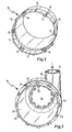
- FIG. 1 shows a first housing part according to the invention in a schematic view
- FIG. 2 shows a second housing part according to the invention, likewise in a schematic view
- Figure 3 shows a first embodiment consisting of locking plane and locking cams
- Figure 4 shows a second embodiment of the connection between locking cam and locking plane.
- FIG. 1 shows a cup-shaped first housing part 10 which is essentially hollow-cylindrical in shape and has a cylindrical opening.
- an inner circumferential surface 11 is formed by a shoulder edge 12 in the first housing part 10.
- the diameter of the first housing part 10 makes in the region of the shoulder edge 12 a diameter jump to a larger one Diameter in the area of the opening.
- two different configurations of locking means 13, 14 are arranged at regular intervals.
- the outer surface of the first housing part 10 has in the region of the opening handle cam 15 for handling the first housing part.
- the first housing part is produced in the primary molding process, in particular injection molding process.
- FIG. 2 shows a second likewise substantially pot-shaped cylindrical housing part 16 with an inlet 17 which is arranged tangentially at one end of the second housing part 16 through a connecting piece 18.
- an outlet 19 is arranged concentrically on the end face of the second housing part 16, wherein the outlet 19 has Klipsnasen 20 for sealingly receiving an outlet nozzle, not shown here.
- On the opposite side of the second housing part 16 is caused by a stop edge 21, a diameter jump, whereby the diameter of the housing in the region of an opening 24 which is disposed opposite to the outlet 19, is less than on the opposite side of the opening 24.
- an outer lateral surface 22 is formed at the corresponding distance to the latching planes 13, 14 of the first figure locking cam 23 are arranged.
- the locking cam 23 has a parallel to the direction of rotation of the two housing halves 10, 16 lying active surface 25 and two peaks 26 which over 27 surfaces the active surface 25 are connected.
- the shape of the detent cam 23 is similar to an open U, the shape being such was chosen to avoid accumulation of material. Other forms are also conceivable, wherein the active surface 25 and the surfaces 27 arranged perpendicular thereto must be maintained.
- the locking cams 23, which are arranged in the second housing part 16, are positioned there in such a way that the opening of the U points in the direction of the opening 24.
- the first embodiment of the latching plane 13 of the first housing part 10 also has an active surface 28, which is also parallel to the direction of rotation of the two housing halves 10, 16 to each other, as the active surface 25 of the locking cam 23.
- Active surface 29 is provided, which corresponds to one of the surfaces 27 of the locking cam 23 and thus forms a radial end stop.
- the locking plane 13 has an obliquely arranged to the effective surface 28 impact plane 30 which opens at its highest points in a crest 31.
- the overall shape of the detent plane 13 is roughly comparable to a horizontal L, with the active surface 28 and the short leg of the L's pointing in the direction of the closed first housing part 10.
- the locking cam 23 and the first locking plane 13 are in the connected state of the two housing parts 10, 16 via a holding plane 32 and a Radialab gleichebene 33 in contact.
- the holding plane 32 determines the locking forces in the axial direction and the axial clearance and the radial plane 33 determines the radial clearance.
- the second detent plane 14 in this case has an effective surface 34 which is arranged at an angle ⁇ 2 to the plane of rotation and which transmits the torque during the Closing the connection determines and another active surface 35 which is arranged at an angle ⁇ 1 to the rotation plane and determines the torque when opening the connection on.
- the height difference a between the intersection of the active surfaces 34 and 35 and the active surface 25 of the locking cam 23 determines the locking force of the connection in the radial direction.
- the angle ⁇ 2 determines the torque to close the connection, which is between zero and sixty degrees, preferably between five and thirty degrees.
Applications Claiming Priority (1)
| Application Number | Priority Date | Filing Date | Title |
|---|---|---|---|
| DE102004000056A DE102004000056A1 (de) | 2004-11-25 | 2004-11-25 | Gehäuse |
Publications (2)
| Publication Number | Publication Date |
|---|---|
| EP1661614A1 true EP1661614A1 (fr) | 2006-05-31 |
| EP1661614B1 EP1661614B1 (fr) | 2007-12-12 |
Family
ID=35871016
Family Applications (1)
| Application Number | Title | Priority Date | Filing Date |
|---|---|---|---|
| EP05109441A Not-in-force EP1661614B1 (fr) | 2004-11-25 | 2005-10-11 | Boîtier |
Country Status (5)
| Country | Link |
|---|---|
| US (1) | US7442222B2 (fr) |
| EP (1) | EP1661614B1 (fr) |
| JP (1) | JP4974132B2 (fr) |
| AT (1) | ATE380574T1 (fr) |
| DE (2) | DE102004000056A1 (fr) |
Cited By (5)
| Publication number | Priority date | Publication date | Assignee | Title |
|---|---|---|---|---|
| EP2096296A1 (fr) * | 2008-02-29 | 2009-09-02 | Mann+Hummel Gmbh | Boîtier de filtre |
| DE202009001239U1 (de) * | 2009-02-02 | 2010-06-24 | Mann+Hummel Gmbh | Filtereinrichtung zur Filtration von Fluid |
| US7976603B2 (en) | 2007-03-05 | 2011-07-12 | Mann+Hummel Gmbh | Filter housing |
| CN102688632A (zh) * | 2011-03-24 | 2012-09-26 | 曼·胡默尔有限公司 | 空气过滤器的过滤器壳体和过滤器壳体的锁扣元件 |
| CN109611962A (zh) * | 2017-09-15 | 2019-04-12 | 爱客股份公司 | 带有立架的个性化空气净化装置 |
Families Citing this family (23)
| Publication number | Priority date | Publication date | Assignee | Title |
|---|---|---|---|---|
| CN102258918B (zh) | 2004-04-30 | 2016-02-24 | 唐纳森公司 | 过滤器结构;外壳;组件及方法 |
| US7905936B2 (en) * | 2004-04-30 | 2011-03-15 | Donaldson Company, Inc. | Filter arrangements; housing; assemblies; and, methods |
| WO2006009766A1 (fr) | 2004-06-18 | 2006-01-26 | Donaldson Company, Inc. | Agencements de filtre à air, cartouche filtrante prêtes à l’usage et procédés |
| KR101819868B1 (ko) | 2005-10-11 | 2018-01-17 | 도날드슨 컴파니, 인코포레이티드 | 에어 필터 배열, 조립체, 및 방법 |
| WO2007084689A2 (fr) | 2006-01-20 | 2007-07-26 | Donaldson Company, Inc. | Epurateur d’air conçu pour recevoir des cartouches filtrantes de diverses tailles, composants de celui-ci et procedes associes |
| US7972404B2 (en) * | 2006-06-22 | 2011-07-05 | Donaldson Company, Inc. | Air cleaner arrangements; components thereof; and, methods |
| US7713321B2 (en) * | 2006-06-22 | 2010-05-11 | Donaldson Company, Inc. | Air cleaner arrangements; components thereof; and, methods |
| DE202006011994U1 (de) * | 2006-08-03 | 2007-12-06 | Mann + Hummel Gmbh | Luftfiltergehäuse für ein zylindrisches Filterelement |
| WO2009033040A1 (fr) | 2007-09-07 | 2009-03-12 | Donaldson Company, Inc. | Ensemble filtre à air, ses composants et ses procédés |
| DE202008007294U1 (de) * | 2008-05-30 | 2009-10-08 | Mann + Hummel Gmbh | Filtertopf mit Drehmomentbegrenzer |
| US7972403B2 (en) * | 2008-08-12 | 2011-07-05 | Mann + Hummel Gmbh | Rotate-once outlet fitting for a filter housing |
| US8105409B2 (en) | 2009-01-30 | 2012-01-31 | General Electric Company | Filter retention system |
| US8048186B2 (en) * | 2009-04-02 | 2011-11-01 | General Electric Company | Filter retention systems and devices |
| US20110056948A1 (en) * | 2009-09-04 | 2011-03-10 | Pacific Management Holding, Llc | Pharmaceutical Container Having Non-Child-Resistant Closure |
| DE102010036294A1 (de) * | 2010-09-03 | 2012-03-08 | Hydac Filtertechnik Gmbh | System zur Be- und Entlüftung von ein Fluidvolumen ethaltenden Behältnissen |
| JP5713289B2 (ja) | 2011-05-09 | 2015-05-07 | Smc株式会社 | 流体圧機器のケース構造 |
| JP5765560B2 (ja) * | 2011-05-09 | 2015-08-19 | Smc株式会社 | フィルタ装置 |
| US10722990B2 (en) | 2016-09-15 | 2020-07-28 | General Electric Company | Method for installing and removing modularized silencer baffles |
| US10119469B2 (en) | 2016-09-15 | 2018-11-06 | General Electric Company | Method and apparatus for modularized inlet silencer baffles |
| CN108278157B (zh) | 2017-01-06 | 2022-08-02 | 通用电气公司 | 用于改进的入口消音挡板的系统和方法 |
| CN108278158B (zh) | 2017-01-06 | 2022-05-13 | 通用电气公司 | 用于改进的入口消音挡板的系统和方法 |
| US10603616B1 (en) * | 2017-08-24 | 2020-03-31 | American Air Filter Company, Inc. | Reusable filter frame |
| US10688428B2 (en) | 2017-12-05 | 2020-06-23 | Mann+Hummel Gmbh | Housing and filter system having a housing |
Citations (3)
| Publication number | Priority date | Publication date | Assignee | Title |
|---|---|---|---|---|
| US4215790A (en) * | 1979-05-14 | 1980-08-05 | Wilkerson Corporation | Guard for compressed air fitting bowl |
| WO1999014483A1 (fr) | 1997-09-12 | 1999-03-25 | Donaldson Company, Inc. | Ensemble epurateur d'air et procede correspondant |
| US6299661B1 (en) * | 1999-05-12 | 2001-10-09 | Siemens Canada Limited | Twist fit connection for air cleaners |
Family Cites Families (14)
| Publication number | Priority date | Publication date | Assignee | Title |
|---|---|---|---|---|
| US4333580A (en) * | 1980-09-29 | 1982-06-08 | Associated Plastics, Inc. | Mechanism for locking two halves of an underground vault |
| NZ221504A (en) * | 1986-08-21 | 1990-04-26 | Elconnex Pty Ltd | Junction box with bayonet type connections for conduits and lid |
| US5207463A (en) * | 1989-10-10 | 1993-05-04 | Solvay Automotive, Inc. | Fuel sender locking ring |
| US4998639A (en) * | 1989-10-10 | 1991-03-12 | Solvay Automotive, Inc. | Fuel sender locking ring |
| US5320233A (en) * | 1993-08-30 | 1994-06-14 | Aluminum Company Of America | Tamper evident lug cap |
| US5443175A (en) * | 1994-04-19 | 1995-08-22 | Crown Cork & Seal Company, Inc. | Resealable closure device |
| US5529201A (en) * | 1994-05-20 | 1996-06-25 | Stant Manufacturing Inc. | Cam-on filler neck cap |
| EP0779832A1 (fr) * | 1995-07-05 | 1997-06-25 | Air-Maze Corporation | Filtre a air pourvu d'un embout amovible |
| US5800581A (en) * | 1997-04-07 | 1998-09-01 | Air-Maze Corporation | Air cleaner having filter element integrally formed with housing end cap |
| US6051042A (en) * | 1997-09-12 | 2000-04-18 | Donaldson Company, Inc. | Air cleaner assembly |
| US6436162B1 (en) * | 2000-03-22 | 2002-08-20 | Nelson Industries, Inc. | Twist and lock filter housing with anti-rotation stop |
| US6402798B1 (en) * | 2000-09-19 | 2002-06-11 | Nelson Industries, Inc. | Twist and lock filter housing with nontorsional anti-rotation stop |
| US6419718B1 (en) * | 2000-10-13 | 2002-07-16 | Donaldson Company, Inc. | Cover member and air cleaner construction; use; and, method of assembly |
| WO2004002844A1 (fr) * | 2002-06-26 | 2004-01-08 | Dayton Systems Group, Inc. | Recipient et fermeture |
-
2004
- 2004-11-25 DE DE102004000056A patent/DE102004000056A1/de not_active Ceased
-
2005
- 2005-10-11 EP EP05109441A patent/EP1661614B1/fr not_active Not-in-force
- 2005-10-11 AT AT05109441T patent/ATE380574T1/de not_active IP Right Cessation
- 2005-10-11 DE DE502005002208T patent/DE502005002208D1/de active Active
- 2005-11-16 JP JP2005330982A patent/JP4974132B2/ja not_active Expired - Fee Related
- 2005-11-23 US US11/284,889 patent/US7442222B2/en not_active Expired - Fee Related
Patent Citations (3)
| Publication number | Priority date | Publication date | Assignee | Title |
|---|---|---|---|---|
| US4215790A (en) * | 1979-05-14 | 1980-08-05 | Wilkerson Corporation | Guard for compressed air fitting bowl |
| WO1999014483A1 (fr) | 1997-09-12 | 1999-03-25 | Donaldson Company, Inc. | Ensemble epurateur d'air et procede correspondant |
| US6299661B1 (en) * | 1999-05-12 | 2001-10-09 | Siemens Canada Limited | Twist fit connection for air cleaners |
Cited By (8)
| Publication number | Priority date | Publication date | Assignee | Title |
|---|---|---|---|---|
| US7976603B2 (en) | 2007-03-05 | 2011-07-12 | Mann+Hummel Gmbh | Filter housing |
| EP2096296A1 (fr) * | 2008-02-29 | 2009-09-02 | Mann+Hummel Gmbh | Boîtier de filtre |
| DE202009001239U1 (de) * | 2009-02-02 | 2010-06-24 | Mann+Hummel Gmbh | Filtereinrichtung zur Filtration von Fluid |
| US8282700B2 (en) | 2009-02-02 | 2012-10-09 | Mann+Hummel Gmbh | Filter device for filtration of a fluid |
| CN102688632A (zh) * | 2011-03-24 | 2012-09-26 | 曼·胡默尔有限公司 | 空气过滤器的过滤器壳体和过滤器壳体的锁扣元件 |
| CN102688632B (zh) * | 2011-03-24 | 2016-05-18 | 曼·胡默尔有限公司 | 空气过滤器的过滤器壳体和过滤器壳体的锁扣元件 |
| CN109611962A (zh) * | 2017-09-15 | 2019-04-12 | 爱客股份公司 | 带有立架的个性化空气净化装置 |
| CN109611962B (zh) * | 2017-09-15 | 2021-08-10 | 爱客股份公司 | 带有立架的个性化空气净化装置 |
Also Published As
| Publication number | Publication date |
|---|---|
| JP4974132B2 (ja) | 2012-07-11 |
| DE502005002208D1 (de) | 2008-01-24 |
| US20060121768A1 (en) | 2006-06-08 |
| DE102004000056A1 (de) | 2006-06-08 |
| JP2006153010A (ja) | 2006-06-15 |
| EP1661614B1 (fr) | 2007-12-12 |
| US7442222B2 (en) | 2008-10-28 |
| ATE380574T1 (de) | 2007-12-15 |
Similar Documents
| Publication | Publication Date | Title |
|---|---|---|
| EP1661614B1 (fr) | Boîtier | |
| EP0116157B1 (fr) | Dispositif de connexion coaxiale | |
| EP1343574B1 (fr) | Filtre pour separer des impuretes contenues dans un courant gazeux | |
| DE19830752C2 (de) | Befestigungsclip | |
| EP0208850A2 (fr) | Accouplement à action rapide | |
| EP1266682B1 (fr) | Dispositif à filtre combiné | |
| EP2002151A1 (fr) | Aube de turbine en deux parties | |
| DE4205738A1 (de) | Kuppelnde verbindungselemente | |
| EP1620920B1 (fr) | Composant miniature inductif, notamment antenne | |
| EP1335148B1 (fr) | Corps de soutien, en particulier pour le support élastique d'un meuble d'assise ou de couchage | |
| DE19634198A1 (de) | Elektrischer Stecker mit Montagebrücke | |
| WO1992011468A1 (fr) | Palier lisse radial-axial compose et procede pour sa fabrication | |
| WO1997002422A1 (fr) | Systeme d'admission en matiere thermoplastique | |
| EP0791236B1 (fr) | Commutateur enfichable et son procede de production | |
| DE19725642A1 (de) | Verfahren zur Herstellung eines Verbundes aus zwei Kunststoffteilen | |
| DE10242297A1 (de) | Kugelgewindetrieb | |
| EP2570243B1 (fr) | Grappin pour trous | |
| DE4114036C2 (fr) | ||
| EP3387658A1 (fr) | Ensemble aimant et pièce en plastique magnétique conçue pour un tel ensemble aimant | |
| DE2604325C3 (de) | Wischvorrichtung für Scheiben von Kraftfahrzeugen | |
| EP0945185B1 (fr) | Distributeur de fluide et son procédé de fabrication | |
| EP3668622B1 (fr) | Système de construction | |
| EP1514706B1 (fr) | Fixation par encliquetage pour un boîtier | |
| DE3410782A1 (de) | Steckerelement zur verbindung von spielzeugteilen | |
| DE19810897C1 (de) | Kontaktstift zur lötfreien Befestigung in metallisierten Löchern von Leiterplatten |
Legal Events
| Date | Code | Title | Description |
|---|---|---|---|
| PUAI | Public reference made under article 153(3) epc to a published international application that has entered the european phase |
Free format text: ORIGINAL CODE: 0009012 |
|
| AK | Designated contracting states |
Kind code of ref document: A1 Designated state(s): AT BE BG CH CY CZ DE DK EE ES FI FR GB GR HU IE IS IT LI LT LU LV MC NL PL PT RO SE SI SK TR |
|
| AX | Request for extension of the european patent |
Extension state: AL BA HR MK YU |
|
| 17P | Request for examination filed |
Effective date: 20060704 |
|
| 17Q | First examination report despatched |
Effective date: 20060810 |
|
| AKX | Designation fees paid |
Designated state(s): AT BE BG CH CY CZ DE DK EE ES FI FR GB GR HU IE IS IT LI LT LU LV MC NL PL PT RO SE SI SK TR |
|
| GRAP | Despatch of communication of intention to grant a patent |
Free format text: ORIGINAL CODE: EPIDOSNIGR1 |
|
| GRAS | Grant fee paid |
Free format text: ORIGINAL CODE: EPIDOSNIGR3 |
|
| GRAA | (expected) grant |
Free format text: ORIGINAL CODE: 0009210 |
|
| AK | Designated contracting states |
Kind code of ref document: B1 Designated state(s): AT BE BG CH CY CZ DE DK EE ES FI FR GB GR HU IE IS IT LI LT LU LV MC NL PL PT RO SE SI SK TR |
|
| REG | Reference to a national code |
Ref country code: GB Ref legal event code: FG4D Free format text: NOT ENGLISH |
|
| REG | Reference to a national code |
Ref country code: CH Ref legal event code: EP |
|
| REG | Reference to a national code |
Ref country code: IE Ref legal event code: FG4D Free format text: LANGUAGE OF EP DOCUMENT: GERMAN |
|
| REF | Corresponds to: |
Ref document number: 502005002208 Country of ref document: DE Date of ref document: 20080124 Kind code of ref document: P |
|
| PG25 | Lapsed in a contracting state [announced via postgrant information from national office to epo] |
Ref country code: SE Free format text: LAPSE BECAUSE OF FAILURE TO SUBMIT A TRANSLATION OF THE DESCRIPTION OR TO PAY THE FEE WITHIN THE PRESCRIBED TIME-LIMIT Effective date: 20080312 |
|
| PG25 | Lapsed in a contracting state [announced via postgrant information from national office to epo] |
Ref country code: PL Free format text: LAPSE BECAUSE OF FAILURE TO SUBMIT A TRANSLATION OF THE DESCRIPTION OR TO PAY THE FEE WITHIN THE PRESCRIBED TIME-LIMIT Effective date: 20071212 Ref country code: NL Free format text: LAPSE BECAUSE OF FAILURE TO SUBMIT A TRANSLATION OF THE DESCRIPTION OR TO PAY THE FEE WITHIN THE PRESCRIBED TIME-LIMIT Effective date: 20071212 Ref country code: SI Free format text: LAPSE BECAUSE OF FAILURE TO SUBMIT A TRANSLATION OF THE DESCRIPTION OR TO PAY THE FEE WITHIN THE PRESCRIBED TIME-LIMIT Effective date: 20071212 Ref country code: LV Free format text: LAPSE BECAUSE OF FAILURE TO SUBMIT A TRANSLATION OF THE DESCRIPTION OR TO PAY THE FEE WITHIN THE PRESCRIBED TIME-LIMIT Effective date: 20071212 Ref country code: FI Free format text: LAPSE BECAUSE OF FAILURE TO SUBMIT A TRANSLATION OF THE DESCRIPTION OR TO PAY THE FEE WITHIN THE PRESCRIBED TIME-LIMIT Effective date: 20071212 Ref country code: LT Free format text: LAPSE BECAUSE OF FAILURE TO SUBMIT A TRANSLATION OF THE DESCRIPTION OR TO PAY THE FEE WITHIN THE PRESCRIBED TIME-LIMIT Effective date: 20071212 |
|
| NLV1 | Nl: lapsed or annulled due to failure to fulfill the requirements of art. 29p and 29m of the patents act | ||
| GBV | Gb: ep patent (uk) treated as always having been void in accordance with gb section 77(7)/1977 [no translation filed] | ||
| PG25 | Lapsed in a contracting state [announced via postgrant information from national office to epo] |
Ref country code: ES Free format text: LAPSE BECAUSE OF FAILURE TO SUBMIT A TRANSLATION OF THE DESCRIPTION OR TO PAY THE FEE WITHIN THE PRESCRIBED TIME-LIMIT Effective date: 20080323 Ref country code: CZ Free format text: LAPSE BECAUSE OF FAILURE TO SUBMIT A TRANSLATION OF THE DESCRIPTION OR TO PAY THE FEE WITHIN THE PRESCRIBED TIME-LIMIT Effective date: 20071212 Ref country code: IS Free format text: LAPSE BECAUSE OF FAILURE TO SUBMIT A TRANSLATION OF THE DESCRIPTION OR TO PAY THE FEE WITHIN THE PRESCRIBED TIME-LIMIT Effective date: 20080412 |
|
| ET | Fr: translation filed | ||
| PG25 | Lapsed in a contracting state [announced via postgrant information from national office to epo] |
Ref country code: SK Free format text: LAPSE BECAUSE OF FAILURE TO SUBMIT A TRANSLATION OF THE DESCRIPTION OR TO PAY THE FEE WITHIN THE PRESCRIBED TIME-LIMIT Effective date: 20071212 Ref country code: RO Free format text: LAPSE BECAUSE OF FAILURE TO SUBMIT A TRANSLATION OF THE DESCRIPTION OR TO PAY THE FEE WITHIN THE PRESCRIBED TIME-LIMIT Effective date: 20071212 |
|
| PG25 | Lapsed in a contracting state [announced via postgrant information from national office to epo] |
Ref country code: PT Free format text: LAPSE BECAUSE OF FAILURE TO SUBMIT A TRANSLATION OF THE DESCRIPTION OR TO PAY THE FEE WITHIN THE PRESCRIBED TIME-LIMIT Effective date: 20080512 |
|
| REG | Reference to a national code |
Ref country code: IE Ref legal event code: FD4D |
|
| PLBE | No opposition filed within time limit |
Free format text: ORIGINAL CODE: 0009261 |
|
| STAA | Information on the status of an ep patent application or granted ep patent |
Free format text: STATUS: NO OPPOSITION FILED WITHIN TIME LIMIT |
|
| PG25 | Lapsed in a contracting state [announced via postgrant information from national office to epo] |
Ref country code: DK Free format text: LAPSE BECAUSE OF FAILURE TO SUBMIT A TRANSLATION OF THE DESCRIPTION OR TO PAY THE FEE WITHIN THE PRESCRIBED TIME-LIMIT Effective date: 20071212 Ref country code: IE Free format text: LAPSE BECAUSE OF FAILURE TO SUBMIT A TRANSLATION OF THE DESCRIPTION OR TO PAY THE FEE WITHIN THE PRESCRIBED TIME-LIMIT Effective date: 20071212 |
|
| 26N | No opposition filed |
Effective date: 20080915 |
|
| PG25 | Lapsed in a contracting state [announced via postgrant information from national office to epo] |
Ref country code: GB Free format text: LAPSE BECAUSE OF FAILURE TO SUBMIT A TRANSLATION OF THE DESCRIPTION OR TO PAY THE FEE WITHIN THE PRESCRIBED TIME-LIMIT Effective date: 20071212 |
|
| PG25 | Lapsed in a contracting state [announced via postgrant information from national office to epo] |
Ref country code: GR Free format text: LAPSE BECAUSE OF FAILURE TO SUBMIT A TRANSLATION OF THE DESCRIPTION OR TO PAY THE FEE WITHIN THE PRESCRIBED TIME-LIMIT Effective date: 20080313 |
|
| BERE | Be: lapsed |
Owner name: MANN+HUMMEL G.M.B.H. Effective date: 20081031 |
|
| PG25 | Lapsed in a contracting state [announced via postgrant information from national office to epo] |
Ref country code: EE Free format text: LAPSE BECAUSE OF FAILURE TO SUBMIT A TRANSLATION OF THE DESCRIPTION OR TO PAY THE FEE WITHIN THE PRESCRIBED TIME-LIMIT Effective date: 20071212 Ref country code: BG Free format text: LAPSE BECAUSE OF FAILURE TO SUBMIT A TRANSLATION OF THE DESCRIPTION OR TO PAY THE FEE WITHIN THE PRESCRIBED TIME-LIMIT Effective date: 20080312 |
|
| PG25 | Lapsed in a contracting state [announced via postgrant information from national office to epo] |
Ref country code: MC Free format text: LAPSE BECAUSE OF NON-PAYMENT OF DUE FEES Effective date: 20081031 |
|
| PG25 | Lapsed in a contracting state [announced via postgrant information from national office to epo] |
Ref country code: CY Free format text: LAPSE BECAUSE OF FAILURE TO SUBMIT A TRANSLATION OF THE DESCRIPTION OR TO PAY THE FEE WITHIN THE PRESCRIBED TIME-LIMIT Effective date: 20071212 |
|
| PG25 | Lapsed in a contracting state [announced via postgrant information from national office to epo] |
Ref country code: BE Free format text: LAPSE BECAUSE OF NON-PAYMENT OF DUE FEES Effective date: 20081031 |
|
| PG25 | Lapsed in a contracting state [announced via postgrant information from national office to epo] |
Ref country code: AT Free format text: LAPSE BECAUSE OF NON-PAYMENT OF DUE FEES Effective date: 20081011 |
|
| REG | Reference to a national code |
Ref country code: CH Ref legal event code: PL |
|
| PG25 | Lapsed in a contracting state [announced via postgrant information from national office to epo] |
Ref country code: LU Free format text: LAPSE BECAUSE OF NON-PAYMENT OF DUE FEES Effective date: 20081011 Ref country code: HU Free format text: LAPSE BECAUSE OF FAILURE TO SUBMIT A TRANSLATION OF THE DESCRIPTION OR TO PAY THE FEE WITHIN THE PRESCRIBED TIME-LIMIT Effective date: 20080613 |
|
| PG25 | Lapsed in a contracting state [announced via postgrant information from national office to epo] |
Ref country code: TR Free format text: LAPSE BECAUSE OF FAILURE TO SUBMIT A TRANSLATION OF THE DESCRIPTION OR TO PAY THE FEE WITHIN THE PRESCRIBED TIME-LIMIT Effective date: 20071212 |
|
| PG25 | Lapsed in a contracting state [announced via postgrant information from national office to epo] |
Ref country code: LI Free format text: LAPSE BECAUSE OF NON-PAYMENT OF DUE FEES Effective date: 20091031 Ref country code: CH Free format text: LAPSE BECAUSE OF NON-PAYMENT OF DUE FEES Effective date: 20091031 |
|
| PGFP | Annual fee paid to national office [announced via postgrant information from national office to epo] |
Ref country code: FR Payment date: 20131022 Year of fee payment: 9 |
|
| PGFP | Annual fee paid to national office [announced via postgrant information from national office to epo] |
Ref country code: IT Payment date: 20131025 Year of fee payment: 9 |
|
| REG | Reference to a national code |
Ref country code: FR Ref legal event code: ST Effective date: 20150630 |
|
| PG25 | Lapsed in a contracting state [announced via postgrant information from national office to epo] |
Ref country code: FR Free format text: LAPSE BECAUSE OF NON-PAYMENT OF DUE FEES Effective date: 20141031 Ref country code: IT Free format text: LAPSE BECAUSE OF NON-PAYMENT OF DUE FEES Effective date: 20141011 |
|
| PGFP | Annual fee paid to national office [announced via postgrant information from national office to epo] |
Ref country code: DE Payment date: 20151022 Year of fee payment: 11 |
|
| REG | Reference to a national code |
Ref country code: DE Ref legal event code: R119 Ref document number: 502005002208 Country of ref document: DE |
|
| PG25 | Lapsed in a contracting state [announced via postgrant information from national office to epo] |
Ref country code: DE Free format text: LAPSE BECAUSE OF NON-PAYMENT OF DUE FEES Effective date: 20170503 |