EP1658207B1 - Umlenkelement für sicherheitsgurte mit einstückigem verkleidungsteil - Google Patents
Umlenkelement für sicherheitsgurte mit einstückigem verkleidungsteil Download PDFInfo
- Publication number
- EP1658207B1 EP1658207B1 EP04763761A EP04763761A EP1658207B1 EP 1658207 B1 EP1658207 B1 EP 1658207B1 EP 04763761 A EP04763761 A EP 04763761A EP 04763761 A EP04763761 A EP 04763761A EP 1658207 B1 EP1658207 B1 EP 1658207B1
- Authority
- EP
- European Patent Office
- Prior art keywords
- metal body
- deflector element
- element according
- lining part
- displacement
- Prior art date
- Legal status (The legal status is an assumption and is not a legal conclusion. Google has not performed a legal analysis and makes no representation as to the accuracy of the status listed.)
- Expired - Lifetime
Links
Images


Classifications
-
- B—PERFORMING OPERATIONS; TRANSPORTING
- B60—VEHICLES IN GENERAL
- B60R—VEHICLES, VEHICLE FITTINGS, OR VEHICLE PARTS, NOT OTHERWISE PROVIDED FOR
- B60R22/00—Safety belts or body harnesses in vehicles
- B60R22/18—Anchoring devices
- B60R22/24—Anchoring devices secured to the side, door, or roof of the vehicle
Definitions
- the invention relates to a deflecting element for a safety belt in motor vehicles, consisting of a one-piece metal body with a fastening eye and provided with a rounded tread Gurt Evaluationsschlitz and made of a plastic and held on the metal body garment panel and from a gap width for the passage of the webbing through the Gurt Equipmentsschlitz limiting displacement body, wherein the metal body is formed at its tread forming lower web with an outwardly open C-shaped cross-section.
- a deflection element with the aforementioned features is in the DE 202 05 570 U1 described.
- a trim panel is mounted on the metal body, which consists of two plastic side panels , which are each pushed from the side on the metal body and are held together at its joint via there formed connectors.
- the displacer body covering the portion of the metal body covering the attachment eyelet is fixed to the metal body.
- the invention has for its object to provide a deflecting element with a covered by a cowling area below the Gurt Equipmentsschlitzes a simplified manufacture and assembly.
- the invention provides, in the case of a deflection element having the generic features, that the edge region formed as a one-piece body with the metal body at least partially enclosing Covering part at its the lower web of the metal body enclosing part has a groove for receiving the outer wall of the C-shaped cross-section, and that the at least partially compliant formed trim part aufbiegbar during assembly and is slipped over the metal body such that the trim part mounted in State can be fixed to the metal body by one of the applied to the metal body edge regions on the metal body bias applied.
- the invention is thus based on the concept of forming the trim part as one of a surface side of the metal body forth on this applied and uniform and one-piece component, which is to be attached to the metal body in only one assembly step.
- the existing plastic and so far compliant to a certain extent fairing part fleecebiegen during assembly so far that it is slipped over the metal body.
- the invention has the advantage that in the region of the lower web of the metal body, a positive retention of the trim part is given to the metal body. Furthermore, the trim part is dimensioned in such a way that in the assembled state its edge regions bear against the metal body with prestressing and thereby the trim part is held on the metal body.
- the holder of the covering part can be improved by the fact that clip holders for fixing the covering part to the metal body are formed on the covering part; In this case, it may be expedient if at least part of the metal body bordering edge regions itself is designed as Klipshalterept.
- the metal body at its the Gurt Resultssschlitz for fastening eye-limiting upper web a multi-angled course with a centrally in the Gurt Entrysschlitz projecting lobes with at an angle of about 45 degrees to the longitudinal axis of the Gurt Entrysschlitzes extending boundary edges and the Displacement body has a shape-related contour for covering the attachment eye receiving portion of the metal body including the flap;
- the displacement body has projections protruding into the fastening eye of the metal body and forming a receptacle for a fastening means.
- the displacement body has in its upper, the attachment eye encompassing area over the contour of the metal body protruding lugs as a limitation of the rotational path of the built-in motor vehicle deflecting element to the fastening means.
- the covering part has a partition formed by a slot in its region encompassing the fastening eyelet; this division facilitates the bending of the trim part in the slipping over of the trim part over the metal body;
- the separately formed as in the prior art displacement body is clipped to the metal body, for which purpose clip holders can be provided.
- the displacement body is integral with the covering part;
- the covering part is designed as a closed component and can preferably be fixed to the metal body via correspondingly provided clip holders.
- the covering part including displacement body is formed in an injection process around the metal body around, so that thereby the one-piece design of the displacement body and trim part is realized.
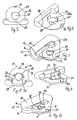
- the metal body 10 of a deflection element for a safety belt in motor vehicles can be seen, which essentially with the in the generic state of the art after DE 202 05 570 U1 matches.
- the metal body 10 preferably made of sheet steel by way of cold forming has a flat upper portion 11 with a fastening eye 12 formed therein for the passage of a fastening means, not shown, for fastening the metal body 10 to a vehicle part.
- the metal body 10 widens by transition into a C-profile 15 with correspondingly spaced walls 16 in a region in which a Gurt Adjustsschlitz 13 is formed, wherein the formed by the C-profile 15 lower web 14 of Metal body 10 has a particular rounded tread for guided through the Gurt Equipmentsschlitz 13 webbing of the seat belt.
- the upper, directed to the attachment eyelet 12 boundary of the Gurt operationsschlitzes 13 is formed by a multi-angled course with a centrally in the Gurt Entrysschlitz 13 projecting lobes 14 at an angle of about 45 degrees to the longitudinal axis of the Gurt Entrysschlitzes 13 boundary edges 18, which through this training between the boundary edges and the attachment lug a larger material area is left, which improves the stability of the metal body 10.
- a uniform and one-piece trim part 19 recognizable which is tuned in its contour to the dimensions of the metal body 10 such that it is fixed solely by an applied bias to the metal body 10.
- the cowling 19 in addition to a Gurt Equipmentsschlitz 13 of the metal body 10 including the flap 17 forming portion of the metal body 10 ausquaintden central opening 20 in its upper region quarter-circular boundaries 21 for partially enclosing the attachment eye 12 of the metal body 10, wherein the boundaries 21 through a slot 22 are divided so that thereby a corresponding compliance of the trim part 19 is set.
- the covering part 19 has the outer contour of the metal body bordering edge portions 25, further in the region of the lower web 14 of the metal body 10 covering or enclosing area a groove 23 for receiving a wall 16 of the C-profile 15, so that in this area a positive retention of the trim part 19 is realized on the metal body 10.
- the further mounting of the trim part 19 on the metal body 10 is realized via the bias exerted by the edge regions 25.
- FIG. 3 shows, the cowling 19 is not executed on its in the installation situation not visible side in the solid cross section, but with webs formed by material recesses 24th
- the DE 202 05 570 U1 belongs to the in the FIGS. 2 to 4 shown one-piece trim part 19 a in the FIGS. 5 to 7 or 8 to 10 shown in different embodiments displacement body 26, the function of which is described in detail in the prior art.
- the cover for the upper portion 11 of the Metal body 10 provided displacement body 26 has an in the assembled state with the attachment eye 12 of the metal body 10 aligned eyelet 27, in the edge region in the attachment eye 12 of the metal body 10 extending projections 28 are formed, which is prevented in the assembled state that the fastening means for fastening the Deflection fitting on the vehicle-fixed part comes into contact with the edge region of the attachment eye in the metal body.
- the displacement body 26 has a lobe 17 of the metal body 10 cross and the Gurt Adjustsschlitz 13 of the metal body 10 partially covering the boundary web 29, by means of which the gap width of the belt slot formed in the deflecting element is ultimately defined.
- a clip projection 30 is formed in the region of the upper edge of the displacement body 26;
- the projections 28 are also provided with corresponding clip hooks 28a, so that in this way the displacement body 26 can be fixed to the metal body 10.
- FIGS. 8 to 10 illustrated embodiment of the displacement body 26 differs from that in the FIGS. 5 to 7 illustrated embodiment essentially in that the displacement body 26 has in its upper, the attachment eye 12 of the metal body 10 bordering area over the contour of the metal body protruding lugs 31, which serve as a limitation of the rotational path of the built-in deflection motor element to its fastening means. Furthermore, additional clip holders 32 are provided which are arranged in the region of the boundary web 29 and border the boundary edges 18 of the metal body 10.
- trim panel 19 and displacement body 26 integrally formed, so that there is a unitary component, which can be produced in a manufacturing process, wherein only a single assembly step for the production of the deflection element is required.
Landscapes
- Engineering & Computer Science (AREA)
- Mechanical Engineering (AREA)
- Automotive Seat Belt Assembly (AREA)
- Connection Of Plates (AREA)
- Clamps And Clips (AREA)
- Refuge Islands, Traffic Blockers, Or Guard Fence (AREA)
- Vehicle Interior And Exterior Ornaments, Soundproofing, And Insulation (AREA)
Priority Applications (1)
| Application Number | Priority Date | Filing Date | Title |
|---|---|---|---|
| DE202004021308U DE202004021308U1 (de) | 2003-08-26 | 2004-08-04 | Umlenkelement für Sicherheitsgurte mit einstückigem Verkleidungsteil |
Applications Claiming Priority (2)
| Application Number | Priority Date | Filing Date | Title |
|---|---|---|---|
| DE10339562 | 2003-08-26 | ||
| PCT/EP2004/008704 WO2005021338A1 (de) | 2003-08-26 | 2004-08-04 | Umlenkelement für sicherheitsgurte mit einstückigem verkleidungsteil |
Publications (2)
| Publication Number | Publication Date |
|---|---|
| EP1658207A1 EP1658207A1 (de) | 2006-05-24 |
| EP1658207B1 true EP1658207B1 (de) | 2009-11-25 |
Family
ID=34258248
Family Applications (1)
| Application Number | Title | Priority Date | Filing Date |
|---|---|---|---|
| EP04763761A Expired - Lifetime EP1658207B1 (de) | 2003-08-26 | 2004-08-04 | Umlenkelement für sicherheitsgurte mit einstückigem verkleidungsteil |
Country Status (7)
| Country | Link |
|---|---|
| US (1) | US7581758B2 (https=) |
| EP (1) | EP1658207B1 (https=) |
| JP (1) | JP4693775B2 (https=) |
| CN (1) | CN101309822B (https=) |
| DE (1) | DE502004010429D1 (https=) |
| ES (1) | ES2335998T3 (https=) |
| WO (1) | WO2005021338A1 (https=) |
Families Citing this family (4)
| Publication number | Priority date | Publication date | Assignee | Title |
|---|---|---|---|---|
| DE10317709B4 (de) * | 2003-04-17 | 2005-05-12 | Autoliv Development Ab | Umlenkvorrichtung für einen Sicherheitsgurt |
| DE10332535A1 (de) † | 2003-07-17 | 2005-02-03 | Trw Occupant Restraint Systems Gmbh & Co. Kg | Umlenkbeschlag für einen Sicherheitsgurt |
| JP4925445B2 (ja) * | 2007-04-13 | 2012-04-25 | タカタ株式会社 | ベルトガイドアンカーおよびこれを備えたシートベルト装置 |
| DE102007048225B4 (de) * | 2007-10-08 | 2022-04-07 | Autoliv Development Ab | Umlenker für das Sicherheitsgurt-System eines Fahrzeuges |
Family Cites Families (10)
| Publication number | Priority date | Publication date | Assignee | Title |
|---|---|---|---|---|
| GB1280153A (en) | 1968-05-07 | 1972-07-05 | Teleflex Ltd Formerly Known As | Improvements in pillar loops |
| GB8421279D0 (en) * | 1984-08-22 | 1984-09-26 | Baldwin J E | Antibiotics |
| GB8422190D0 (en) * | 1984-09-03 | 1984-10-10 | Ase Uk Ltd | Belt guides |
| US4861070A (en) * | 1987-11-27 | 1989-08-29 | Ford Motor Company | Seatbelt guide ring with anti-twist feature |
| DE69509073T2 (de) * | 1994-02-17 | 1999-11-11 | Breed Automotive Technology, Inc. | Umlenkung für einen sicherheitsgurt |
| US6168206B1 (en) * | 1998-03-02 | 2001-01-02 | Trw Vehicle Safety Systems Inc. | Assembly for protecting a vehicle occupant's head from an impact |
| JP2001138862A (ja) * | 2000-10-04 | 2001-05-22 | Mutsumichi Kenkyusho:Kk | ベルト連結用金具 |
| DE10153062C1 (de) | 2001-10-30 | 2003-04-24 | Norbert Janz | Bauelementensatz für Umlenkelemente von Sicherheitsgurtsystemen in Kraftfahrzeugen |
| US6929286B2 (en) * | 2002-08-26 | 2005-08-16 | Autoliv Asp, Inc. | Energy absorbing turning loop cover |
| DE10332535A1 (de) * | 2003-07-17 | 2005-02-03 | Trw Occupant Restraint Systems Gmbh & Co. Kg | Umlenkbeschlag für einen Sicherheitsgurt |
-
2004
- 2004-08-04 JP JP2006524260A patent/JP4693775B2/ja not_active Expired - Lifetime
- 2004-08-04 WO PCT/EP2004/008704 patent/WO2005021338A1/de not_active Ceased
- 2004-08-04 ES ES04763761T patent/ES2335998T3/es not_active Expired - Lifetime
- 2004-08-04 EP EP04763761A patent/EP1658207B1/de not_active Expired - Lifetime
- 2004-08-04 DE DE502004010429T patent/DE502004010429D1/de not_active Expired - Lifetime
- 2004-08-04 CN CN2004800307616A patent/CN101309822B/zh not_active Expired - Lifetime
- 2004-08-04 US US10/560,036 patent/US7581758B2/en not_active Expired - Lifetime
Also Published As
| Publication number | Publication date |
|---|---|
| US20070114776A1 (en) | 2007-05-24 |
| DE502004010429D1 (de) | 2010-01-07 |
| EP1658207A1 (de) | 2006-05-24 |
| WO2005021338A1 (de) | 2005-03-10 |
| JP2007503349A (ja) | 2007-02-22 |
| US7581758B2 (en) | 2009-09-01 |
| CN101309822A (zh) | 2008-11-19 |
| ES2335998T3 (es) | 2010-04-07 |
| JP4693775B2 (ja) | 2011-06-01 |
| CN101309822B (zh) | 2012-04-18 |
Similar Documents
| Publication | Publication Date | Title |
|---|---|---|
| EP0380013B1 (de) | Vorrichtung zur Befestigung eines Dachhimmels einer Schiebedach- oder Schiebehebedachkonstruktion | |
| DE60304318T2 (de) | Befestigung einer rohrklemme | |
| DE4309088C2 (de) | Ortsfest einbaubare Scheibe für Kraftfahrzeuge | |
| EP1498324B2 (de) | Umlenkbeschlag für einen Sicherheitsgurt | |
| DE3918802A1 (de) | Schmutzfaengerbefestigung | |
| EP3325315A1 (de) | Befestiger zum lösbaren verbinden eines paneels an einer struktur, abdeckpaneel für ein airbag und fahrzeug mit einer struktur und einem airbag | |
| DE102005028569B4 (de) | Profil und Anordnung zur Befestigung eines Bezugs an einem Trägerkörper, insbesondere einer Kopfstütze eines Kraftfahrzeugs sowie eine damit ausgestattete Kopfstütze | |
| DE10118111B4 (de) | Gurteinfügungsteil | |
| EP1500564A1 (de) | Fahrzeuginsassen-Rückhaltesystem | |
| DE102007043338B4 (de) | Steckzunge für ein Sicherheitsgurtschloss | |
| DE20219689U1 (de) | Befestigungsanordnung für einen Gurtaufroller | |
| EP1658207B1 (de) | Umlenkelement für sicherheitsgurte mit einstückigem verkleidungsteil | |
| EP1613515A1 (de) | Umlenkvorrichtung für einen sicherheitsgurt | |
| DE19841328C1 (de) | Umlenkbeschlag für eine Sicherheitsgurtanordnung | |
| DE102007012039B4 (de) | Seilschuh für eine Sicherheitsgurtanbringung und Baugruppe bestehend aus einem solchen Seilschuh und einem Seil | |
| DE102017203740B4 (de) | Luftausströmeranordnung | |
| DE102006061617A1 (de) | Befestigungsanordnung, insbesondere zum Halten eines Umlenkbeschlags für einen Gurtbandabschnitt eines Sicherheitsgurtes in einem Fahrzeug, sowie Verfahren zum Befestigen eines Umlenkbeschlags an einer Trägerwand | |
| DE202004021308U1 (de) | Umlenkelement für Sicherheitsgurte mit einstückigem Verkleidungsteil | |
| DE102006033544B4 (de) | Sicherheitsgurt-System für ein Kraftfahrzeug und Gurtzunge für ein Sicherheitsgurtsystem | |
| DE102006059096B4 (de) | Baugruppe zur fahrzeugseitigen Befestigung eines Gurtschlosses | |
| DE10052920C1 (de) | Befestigungsendbeschlag für einen Sicherheitsgurt | |
| DE3416677C2 (https=) | ||
| DE10053673B4 (de) | Sicherheitsgurtumlenker | |
| DE10216792C1 (de) | Schloßzunge mit integrierter Umlenkeinrichtung | |
| DE102005059129A1 (de) | Gehäuse eines Verstellantriebes, insbesondere eines Schrittschaltwerkes eines Kraftfahrzeugsitzes |
Legal Events
| Date | Code | Title | Description |
|---|---|---|---|
| PUAI | Public reference made under article 153(3) epc to a published international application that has entered the european phase |
Free format text: ORIGINAL CODE: 0009012 |
|
| 17P | Request for examination filed |
Effective date: 20060223 |
|
| AK | Designated contracting states |
Kind code of ref document: A1 Designated state(s): DE ES FR IT |
|
| DAX | Request for extension of the european patent (deleted) | ||
| RBV | Designated contracting states (corrected) |
Designated state(s): DE ES FR IT |
|
| 17Q | First examination report despatched |
Effective date: 20080526 |
|
| GRAP | Despatch of communication of intention to grant a patent |
Free format text: ORIGINAL CODE: EPIDOSNIGR1 |
|
| GRAS | Grant fee paid |
Free format text: ORIGINAL CODE: EPIDOSNIGR3 |
|
| GRAA | (expected) grant |
Free format text: ORIGINAL CODE: 0009210 |
|
| AK | Designated contracting states |
Kind code of ref document: B1 Designated state(s): DE ES FR IT |
|
| REF | Corresponds to: |
Ref document number: 502004010429 Country of ref document: DE Date of ref document: 20100107 Kind code of ref document: P |
|
| REG | Reference to a national code |
Ref country code: ES Ref legal event code: FG2A Ref document number: 2335998 Country of ref document: ES Kind code of ref document: T3 |
|
| PLBE | No opposition filed within time limit |
Free format text: ORIGINAL CODE: 0009261 |
|
| STAA | Information on the status of an ep patent application or granted ep patent |
Free format text: STATUS: NO OPPOSITION FILED WITHIN TIME LIMIT |
|
| 26N | No opposition filed |
Effective date: 20100826 |
|
| PG25 | Lapsed in a contracting state [announced via postgrant information from national office to epo] |
Ref country code: IT Free format text: LAPSE BECAUSE OF NON-PAYMENT OF DUE FEES Effective date: 20100804 |
|
| PGRI | Patent reinstated in contracting state [announced from national office to epo] |
Ref country code: IT Effective date: 20110616 |
|
| REG | Reference to a national code |
Ref country code: FR Ref legal event code: PLFP Year of fee payment: 13 |
|
| REG | Reference to a national code |
Ref country code: FR Ref legal event code: PLFP Year of fee payment: 14 |
|
| REG | Reference to a national code |
Ref country code: FR Ref legal event code: PLFP Year of fee payment: 15 |
|
| PGFP | Annual fee paid to national office [announced via postgrant information from national office to epo] |
Ref country code: ES Payment date: 20200917 Year of fee payment: 17 Ref country code: FR Payment date: 20200827 Year of fee payment: 17 |
|
| PGFP | Annual fee paid to national office [announced via postgrant information from national office to epo] |
Ref country code: IT Payment date: 20210831 Year of fee payment: 18 |
|
| PG25 | Lapsed in a contracting state [announced via postgrant information from national office to epo] |
Ref country code: FR Free format text: LAPSE BECAUSE OF NON-PAYMENT OF DUE FEES Effective date: 20210831 |
|
| REG | Reference to a national code |
Ref country code: ES Ref legal event code: FD2A Effective date: 20220926 |
|
| PG25 | Lapsed in a contracting state [announced via postgrant information from national office to epo] |
Ref country code: ES Free format text: LAPSE BECAUSE OF NON-PAYMENT OF DUE FEES Effective date: 20210805 |
|
| PGFP | Annual fee paid to national office [announced via postgrant information from national office to epo] |
Ref country code: DE Payment date: 20230828 Year of fee payment: 20 |
|
| REG | Reference to a national code |
Ref country code: DE Ref legal event code: R071 Ref document number: 502004010429 Country of ref document: DE |
|
| PG25 | Lapsed in a contracting state [announced via postgrant information from national office to epo] |
Ref country code: IT Free format text: LAPSE BECAUSE OF NON-PAYMENT OF DUE FEES Effective date: 20220804 |