EP1657421B1 - Steuervorrichtung für eine Brennkraftmaschine - Google Patents
Steuervorrichtung für eine Brennkraftmaschine Download PDFInfo
- Publication number
- EP1657421B1 EP1657421B1 EP05024008.4A EP05024008A EP1657421B1 EP 1657421 B1 EP1657421 B1 EP 1657421B1 EP 05024008 A EP05024008 A EP 05024008A EP 1657421 B1 EP1657421 B1 EP 1657421B1
- Authority
- EP
- European Patent Office
- Prior art keywords
- throttle opening
- target
- intake
- intake pipe
- flow rate
- Prior art date
- Legal status (The legal status is an assumption and is not a legal conclusion. Google has not performed a legal analysis and makes no representation as to the accuracy of the status listed.)
- Ceased
Links
- 238000002485 combustion reaction Methods 0.000 title claims description 18
- 238000011144 upstream manufacturing Methods 0.000 description 7
- 230000006870 function Effects 0.000 description 4
- 238000010586 diagram Methods 0.000 description 3
- 238000004134 energy conservation Methods 0.000 description 3
- 238000000034 method Methods 0.000 description 3
- 230000003197 catalytic effect Effects 0.000 description 2
- 239000000446 fuel Substances 0.000 description 2
- 230000002457 bidirectional effect Effects 0.000 description 1
- 230000006835 compression Effects 0.000 description 1
- 238000007906 compression Methods 0.000 description 1
- 238000006073 displacement reaction Methods 0.000 description 1
- 238000002474 experimental method Methods 0.000 description 1
- 238000012986 modification Methods 0.000 description 1
- 230000004048 modification Effects 0.000 description 1
Images


Classifications
-
- F—MECHANICAL ENGINEERING; LIGHTING; HEATING; WEAPONS; BLASTING
- F02—COMBUSTION ENGINES; HOT-GAS OR COMBUSTION-PRODUCT ENGINE PLANTS
- F02D—CONTROLLING COMBUSTION ENGINES
- F02D41/00—Electrical control of supply of combustible mixture or its constituents
- F02D41/0002—Controlling intake air
-
- F—MECHANICAL ENGINEERING; LIGHTING; HEATING; WEAPONS; BLASTING
- F02—COMBUSTION ENGINES; HOT-GAS OR COMBUSTION-PRODUCT ENGINE PLANTS
- F02D—CONTROLLING COMBUSTION ENGINES
- F02D11/00—Arrangements for, or adaptations to, non-automatic engine control initiation means, e.g. operator initiated
- F02D11/06—Arrangements for, or adaptations to, non-automatic engine control initiation means, e.g. operator initiated characterised by non-mechanical control linkages, e.g. fluid control linkages or by control linkages with power drive or assistance
- F02D11/10—Arrangements for, or adaptations to, non-automatic engine control initiation means, e.g. operator initiated characterised by non-mechanical control linkages, e.g. fluid control linkages or by control linkages with power drive or assistance of the electric type
- F02D11/105—Arrangements for, or adaptations to, non-automatic engine control initiation means, e.g. operator initiated characterised by non-mechanical control linkages, e.g. fluid control linkages or by control linkages with power drive or assistance of the electric type characterised by the function converting demand to actuation, e.g. a map indicating relations between an accelerator pedal position and throttle valve opening or target engine torque
-
- F—MECHANICAL ENGINEERING; LIGHTING; HEATING; WEAPONS; BLASTING
- F02—COMBUSTION ENGINES; HOT-GAS OR COMBUSTION-PRODUCT ENGINE PLANTS
- F02D—CONTROLLING COMBUSTION ENGINES
- F02D41/00—Electrical control of supply of combustible mixture or its constituents
- F02D41/30—Controlling fuel injection
- F02D41/32—Controlling fuel injection of the low pressure type
-
- F—MECHANICAL ENGINEERING; LIGHTING; HEATING; WEAPONS; BLASTING
- F02—COMBUSTION ENGINES; HOT-GAS OR COMBUSTION-PRODUCT ENGINE PLANTS
- F02D—CONTROLLING COMBUSTION ENGINES
- F02D41/00—Electrical control of supply of combustible mixture or its constituents
- F02D41/0002—Controlling intake air
- F02D2041/001—Controlling intake air for engines with variable valve actuation
-
- F—MECHANICAL ENGINEERING; LIGHTING; HEATING; WEAPONS; BLASTING
- F02—COMBUSTION ENGINES; HOT-GAS OR COMBUSTION-PRODUCT ENGINE PLANTS
- F02D—CONTROLLING COMBUSTION ENGINES
- F02D41/00—Electrical control of supply of combustible mixture or its constituents
- F02D41/02—Circuit arrangements for generating control signals
- F02D41/14—Introducing closed-loop corrections
- F02D41/1401—Introducing closed-loop corrections characterised by the control or regulation method
- F02D2041/1433—Introducing closed-loop corrections characterised by the control or regulation method using a model or simulation of the system
- F02D2041/1434—Inverse model
-
- F—MECHANICAL ENGINEERING; LIGHTING; HEATING; WEAPONS; BLASTING
- F02—COMBUSTION ENGINES; HOT-GAS OR COMBUSTION-PRODUCT ENGINE PLANTS
- F02D—CONTROLLING COMBUSTION ENGINES
- F02D2200/00—Input parameters for engine control
- F02D2200/02—Input parameters for engine control the parameters being related to the engine
- F02D2200/04—Engine intake system parameters
- F02D2200/0402—Engine intake system parameters the parameter being determined by using a model of the engine intake or its components
-
- F—MECHANICAL ENGINEERING; LIGHTING; HEATING; WEAPONS; BLASTING
- F02—COMBUSTION ENGINES; HOT-GAS OR COMBUSTION-PRODUCT ENGINE PLANTS
- F02D—CONTROLLING COMBUSTION ENGINES
- F02D2200/00—Input parameters for engine control
- F02D2200/02—Input parameters for engine control the parameters being related to the engine
- F02D2200/04—Engine intake system parameters
- F02D2200/0406—Intake manifold pressure
- F02D2200/0408—Estimation of intake manifold pressure
-
- F—MECHANICAL ENGINEERING; LIGHTING; HEATING; WEAPONS; BLASTING
- F02—COMBUSTION ENGINES; HOT-GAS OR COMBUSTION-PRODUCT ENGINE PLANTS
- F02D—CONTROLLING COMBUSTION ENGINES
- F02D35/00—Controlling engines, dependent on conditions exterior or interior to engines, not otherwise provided for
- F02D35/0007—Controlling engines, dependent on conditions exterior or interior to engines, not otherwise provided for using electrical feedback
-
- Y—GENERAL TAGGING OF NEW TECHNOLOGICAL DEVELOPMENTS; GENERAL TAGGING OF CROSS-SECTIONAL TECHNOLOGIES SPANNING OVER SEVERAL SECTIONS OF THE IPC; TECHNICAL SUBJECTS COVERED BY FORMER USPC CROSS-REFERENCE ART COLLECTIONS [XRACs] AND DIGESTS
- Y02—TECHNOLOGIES OR APPLICATIONS FOR MITIGATION OR ADAPTATION AGAINST CLIMATE CHANGE
- Y02T—CLIMATE CHANGE MITIGATION TECHNOLOGIES RELATED TO TRANSPORTATION
- Y02T10/00—Road transport of goods or passengers
- Y02T10/10—Internal combustion engine [ICE] based vehicles
- Y02T10/40—Engine management systems
Definitions
- the present invention relates to a control device for an internal combustion engine.
- An object of the present invention is to provide a control device for an internal combustion engine capable of accurately obtaining the target throttle opening, and of accurately conducting the engine control.
- a control device for an internal combustion engine having an intake passage and a throttle valve arranged in the intake passage, the control device comprising: target air amount calculating means for calculating a target value of an intake air amount; estimating means for estimating an intake pipe pressure which is a pressure in the intake passage downstream of the throttle valve; target throttle opening calculating means for calculating a target throttle opening required for making the actual intake air amount equal to the target intake air amount, on the basis of the intake pipe pressure estimated by the estimating means; driving means for driving the throttle valve; judging means for judging whether the target throttle opening can be realized by the driving means; and setting means for setting a final target throttle opening to a maximum or minimum throttle opening which can be realized by the driving means when it is judged that the target throttle opening cannot be realized by the driving means; wherein the driving means drives the throttle valve so that the actual throttle opening is made equal to the final target throttle opening, and wherein the estimating means estimates the intake pipe pressure on the basis of the final target throttle opening.
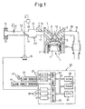
- Fig. 1 shows a case in which the present invention is applied to an internal combustion engine of a spark ignition type.
- the present invention may also be applied to an internal combustion engine of a compression ignition type.
- the reference numeral 1 designates an engine body having four cylinders, for example, 2 designates a cylinder block, 3 designates a cylinder head, 4 designates a piston, 5 designates a combustion chamber, 6 designates intake valves, 7 designates intake ports, 8 designates exhaust valves, 9 designates exhaust ports and 10 designates a spark plug.
- the intake ports 7 are connected to a surge tank 12 through corresponding intake branches 11, and the surge tank 12 is connected to an air cleaner 14 through an intake duct 13.
- a fuel injector 15 is arranged in each intake branch 11, and a throttle valve 17 driven by a step motor 16 is arranged in the intake duct 13.
- the intake duct 13 downstream of the throttle valve 17, the surge tank 12, the intake branches 11, and the intake ports 7 are referred to as an intake pipe IM, in the present specification.
- the exhaust ports 9 are connected via an exhaust manifold 18 and an exhaust pipe 19 to a catalytic converter 20, and the catalytic converter 20 is communicated to the outside air via a muffler (not shown).
- An electronic control unit 30 is constituted of a digital computer including a ROM (read-only memory) 32, a RAM (random access memory) 33, a CPU (microprocessor) 34, an input port 35 and an output port 36, which are connected to each other through a bidirectional bus 31.
- a throttle opening sensor 40 is attached to the throttle valve 17 for detecting an opening of the throttle valve 17, i.e., a throttle opening ⁇ t .
- An air flow meter 41 is attached to the intake duct 13 upstream of the throttle valve 17 for detecting a flow rate of intake air flowing through the intake passage of the engine.
- the air flow meter 41 has a built-in atmospheric temperature sensor for detecting the atmospheric temperature Ta (K).
- an accelerator pedal 42 is connected with a load sensor 43 for detecting a depression ACC of the accelerator pedal 42.
- the depression ACC of the accelerator pedal 42 represents a required load.
- the output voltages of the sensors 40, 41 and 43 are input through corresponding A/D converters 37 to the input port 35.
- the input port 35 is connected with a crank angle sensor 44 for generating an output pulse for each rotation of 30°, for example, of the crankshaft.
- CPU 34 calculates the engine speed NE on the basis of the output pulse from the crank angle sensor 44.
- the output port 36 is connected through corresponding drive circuits 38 to the spark plug 10, the fuel injectors 15, and the step motor 16, which are controlled on the basis of the output signals from the electronic control unit 30.
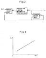
- a target value KLT of an engine load ratio KL (%) representing an amount of intake air is first calculated.
- a target throttle opening ⁇ tT which is a throttle opening required to make the actual engine load ratio KL equal to the target value KLT, is calculated using the target engine load ratio KLT, an intake pipe pressure Pm (kPa) which is a pressure in the intake pipe IM , and a reverse intake model (explained later).
- a final target throttle opening ⁇ tTf is calculated using a process for limiting the movement of a throttle valve (explained later).
- the throttle valve 17 is driven so that the actual throttle opening ⁇ t is made equal to the final target opening ⁇ tTf.
- the intake pipe pressure Pm realized when the actual throttle opening ⁇ t is made equal to the final target throttle opening ⁇ tTf is calculated using the final target opening ⁇ tTf and a forward intake mode (explained later).
- the target engine load ratio KLT, the target throttle opening ⁇ tT, and the final target throttle opening ⁇ tTf are calculated repeatedly, and the target throttle opening ⁇ tT in the next processing cycle is calculated using the thus calculated intake pipe pressure Pm .
- the final target throttle opening ⁇ tTf is calculated using the process for limiting the movement of the throttle valve 17 as in the following. Specifically, in the limiting process in the embodiment according to the present invention, it is judged whether the step motor 16 can realize the target throttle opening ⁇ tT . If it is judged that the step motor 16 cannot realize the target throttle opening ⁇ tT , the final target throttle opening ⁇ tTf is set to a maximum or minimum throttle opening which the step motor 16 can realize.
- the maximum and minimum throttle opening which the step motor 16 can realize are referred to as a changeable maximum throttle opening ⁇ tM and a changeable minimum throttle opening ⁇ tm, respectively
- the final target throttle opening ⁇ tTf is set to the changeable maximum opening ⁇ tM.
- the final target throttle opening ⁇ tTf is set to the changeable minimum opening ⁇ tm.
- the final target opening ⁇ tTf is set to the target opening ⁇ tT.
- the intake pipe pressure Pm is calculated on the basis of the final target throttle opening ⁇ tTf , rather than the target opening ⁇ tT . This ensures an accurate calculation of the intake pipe pressure Pm.
- Mc mc ⁇ tiv
- tiv represents a time period (sec) required for each cylinder to conduct one intake stroke.
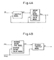
- the target engine load ratio KLT may be calculated on the basis of the depression ACC of the accelerator pedal 42.
- the target engine load ratio KLT in this case is stored in the ROM 32 in advance, in the form of a map shown in Fig. 3 .
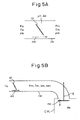
- the reverse intake model and the forward intake model are calculation models modeling the intake air flow. Next, the forward intake model will be explained.
- the forward intake model is constituted by a throttle model, an intake pipe model, and an intake valve model, as shown in Fig. 4A .
- the throttle model is a calculation model which models the intake air flow passing through the throttle valve 17. Note that the temperature of the air in the intake pipe IM is referred to as an intake pipe temperature Tm (K).
- the throttle valve passing-through air flow rate mt calculated from the equation (7) represents a throttle valve passing-through air flow rate realized when the intake pipe pressure is equal to Pm and, at this time, the throttle opening is turned to ⁇ t .
- the intake pipe model is a calculation model modeling the intake air flow in the intake pipe IM.
- the intake pipe model of the embodiment according to the present invention focuses on the mass conservation law and the energy conservation law regarding the intake pipe IM. Specifically, the flow rate of air entering the intake pipe IM is equal to the throttle valve passing-through air flow rate mt and the flow rate of air exiting from the intake pipe IM is equal to the in-cylinder intake air flow rate mc , as shown in Fig.
- T ⁇ m i P ⁇ m i PBYT i
- the intake pipe pressure Pm(i) calculated from the equation (13) represents an intake pipe pressure realized when the intake pipe pressure and temperature are equal to Pm(i-1) and Tm(i-1) and, at this time, air enters in the intake pipe IM by mt(i-1) and exits from the intake pipe IM by mc(i-1) .
- the intake valve model is a calculation model modeling the intake air flow passing through the intake valve 6.
- the in-cylinder intake air flow rate mc calculated from the equation (15) represents an in-cylinder intake air flow rate realized when the intake pipe pressure is equal to Pm .
- the intake pipe pressure Pm calculated from the equation (13) using the throttle valve passing-through air flow rate mt calculated from the equation (7) while ( ⁇ t, Pm ) in the equation (7) are replaced with ( ⁇ tTf, Pmo ), the in-cylinder intake air flow rate mc calculated from the equation (15), and the intake pipe temperature Tm calculated from the equations (12) and (14), represents an intake pipe pressure realized when the actual throttle opening ⁇ t is made equal to the final target throttle opening ⁇ tTf.
- Pmo represents an intake pipe pressure Pm in the previous calculation cycle.
- the reverse intake model is constituted by a reverse throttle model, a reverse intake pipe model, and a reverse intake valve model, as shown in Fig. 4B .
- the reverse throttle model, the reverse intake pipe model, and the reverse intake valve model are for performing calculations in reverse direction in the throttle model, the intake pipe model, and the intake valve model, respectively.
- the intake pipe pressure Pm calculated from the equation (16) while mt in the equation (16) is replaced with mcT, represents a target value PmT of the intake pipe pressure Pm, where mcT represents a target value of the in-cylinder intake air flow rate mc corresponding to the target engine load ratio KLT.
- the throttle valve passing-through air flow rate mt calculated from the equation (17) while Pm in the equation (17) is replaced with PmT , represents a target value mtT of the throttle valve passing-through air flow rate mt.
- the throttle opening ⁇ t calculated from the equation (18) while mt in the equation (18) is replaced with mtT, represents the target throttle opening ⁇ tT required for making the actual engine load ratio KL equal to the target engine load ratio KLT.
- Fig. 8 shows a calculation routine of the final target throttle opening ⁇ tTf according to the embodiment of the present invention. This routine is executed by an interruption every predetermined time.
- step 100 the target engine load ratio KLT is calculated from the map shown in Fig. 3 .
- the target throttle opening ⁇ tT is calculated using the reverse intake model.
- step 103 it is judged whether the target throttle opening ⁇ tT is larger than the changeable maximum throttle opening ⁇ tM. If ⁇ tT> ⁇ tM, the routine goes to step 104 where the final target throttle opening ⁇ tTf is set to the changeable maximum throttle opening ⁇ tM.
- step 108 the routine goes to step 108.
- the routine goes to step 105 where it is judged whether the target throttle opening ⁇ tT is smaller than the changeable minimum throttle opening ⁇ tm. If ⁇ tT ⁇ tm, the routine goes to step 106 where the final target throttle opening ⁇ tTf is set to the changeable minimum throttle opening ⁇ tm. Then, the routine goes to step 108. If ⁇ tT ⁇ tm or ⁇ tm ⁇ tT ⁇ tM, the routine goes from step 105 to step 107 where the final target throttle opening ⁇ tTf is set to the target throttle opening ⁇ tT . Then, the routine goes to step 108.
- step 108 the intake pipe pressure Pm is calculated using the forward intake model.
- step 109 ( ⁇ tTf, Pm, Tm ) calculated in the current processing cycle are replaced with ( ⁇ tTfo, Pmo, Tmo), respectively.
- control device for an internal combustion engine capable of accurately obtaining the target throttle opening, and of accurately conducting the engine control.
- a target value of an engine load ratio is calculated.
- a target throttle opening required for making the actual engine load ratio equal to the target engine load ratio is calculated on the basis of an intake pipe pressure which is a pressure in the intake passage downstream of the throttle valve. It is judged whether the target throttle opening can be realized by a step motor.
- a final target throttle opening is set to a maximum or minimum throttle opening which can be realized by the step motor when it is judged that the calculated target throttle opening cannot be realized by the step motor.
- the step motor drives the throttle valve so that the actual throttle opening is made equal to the final target throttle opening, and the intake pipe pressure is estimated on the basis of the final target throttle opening.
Landscapes
- Engineering & Computer Science (AREA)
- Chemical & Material Sciences (AREA)
- Combustion & Propulsion (AREA)
- Mechanical Engineering (AREA)
- General Engineering & Computer Science (AREA)
- Electrical Control Of Air Or Fuel Supplied To Internal-Combustion Engine (AREA)
- Combined Controls Of Internal Combustion Engines (AREA)
Claims (8)
- Steuervorrichtung für eine Brennkraftmaschine mit einer Einlasspassage und einem in der Einlasspassage angeordnetem Drosselventil, mit:einer Soll-Luftmengenberechnungseinrichtung zum Berechnen eines Sollwerts einer Einlassluftmenge;einer Abschätzeinrichtung zum wiederholten Abschätzen eines Einlassrohrdrucks, der ein Druck in der Einlasspassage stromabwärtig des Drosselventils ist;einer Soll-Drosselöffnungsberechnungseinrichtung zum Berechnen einer Soll-Drosselöffnung, die notwendig ist, um die gegenwärtige Einlassluftmenge gleich der Soll-Einlassluftmenge zu machen, auf der Grundlage des Einlassrohrdrucks;einer Antriebseinrichtung zum Antreiben des Drosselventils;einer Beurteilungseinrichtung zum Beurteilen, ob die Soll-Drosselöffnung durch die Antriebseinrichtung realisiert werden kann; undeiner Einstelleinrichtung zum Einstellen einer finalen Soll-Drosselöffnung auf eine maximale oder minimale Drosselöffnung, die durch die Antriebseinrichtung realisiert werden kann, wenn beurteilt wird, dass die Soll-Drosselöffnung nicht durch die Antriebseinrichtung realisiert werden kann;wobei die Antriebseinrichtung das Drosselventil derart antreibt, dass die gegenwärtige Drosselöffnung gleich der finalen Soll-Drosselöffnung gemacht wird, undwobei die Abschätzeinrichtung den neuen Einlassrohrdruck auf der Grundlage der finalen Soll-Drosselöffnung abschätzt.
- Steuervorrichtung für eine Brennkraftmaschine gemäß Anspruch 1, wobei die Einstelleinrichtung die finale Soll-Drosselöffnung auf die durch die Soll-Drosselöffnungsberechnungseinrichtung berechnete Soll-Drosselöffnung einstellt, wenn beurteilt wird, dass die Soll-Drosselöffnung durch die Antriebseinrichtung realisiert werden kann.
- Steuervorrichtung für eine Brennkraftmaschine gemäß Anspruch 1, wobei die Abschätzeinrichtung abschätzt:eine Drosselventildurchlaufluftdurchflussrate, die eine Luftdurchflussrate ist, die eine Durchflussrate der durch das Drosselventil strömenden Luft ist, auf der Grundlage des zuvor abgeschätzten Einlassrohrdrucks und der finalen Soll-Drosselöffnung;eine zylinderinterne Einlassluftdurchflussrate, die eine Durchflussrate von aus der Einlasspassage in den Zylinder angesaugten Luft ist, auf der Grundlage des zuvor abgeschätzten Einlassrohrdrucks; undden neuen Einlassrohrdruck, auf der Grundlage des zuvor abgeschätzten Einlassrohrdrucks, der abgeschätzten Drosselventildurchlaufsluftdurchflussrate und der abgeschätzten zylinderinternen Einlassluftdurchflussrate.
- Steuervorrichtung für eine Brennkraftmaschine gemäß Anspruch 1, wobei die Soll-Drosselöffnungsberechnungseinrichtung berechnet:einen Sollwert einer zylinderinternen Einlassluftdurchflussrate, die eine Durchflussrate von aus der Einlasspassage in den Zylinder angesaugten Luft ist, auf der Grundlage der Soll-Einlassluftmenge;einen Sollwert des Einlassrohrdrucks, auf der Grundlage der berechneten zylinderinternen Soll-Einlassluftdurchflussrate;einen Sollwert der Drosselventildurchlaufsluftdurchflussrate, die eine Durchflussrate von durch das Drosselventil strömenden Luft ist, auf der Grundlage des zuvor abgeschätzten Einlassrohrdrucks und des berechneten Soll-Einlassrohrdrucks; unddie Soll-Drosselöffnung, auf der Grundlage des zuvor abgeschätzten Einlassrohrdrucks und der berechneten Soll-Drosselventildurchlaufsluftdurchflussrate.
- Steuervorrichtung für eine Brennkraftmaschine gemäß Anspruch 1, wobei die maximale Drosselöffnung, die durch die Antriebseinrichtung realisiert werden kann, durch Addieren einer maximalen Schwankung der Drosselöffnung zu der gegenwärtigen Drosselöffnung erhalten wird, und es beurteilt wird, dass die durch die Soll-Drosselöffnungsberechnungseinrichtung berechnete Soll-Drosselöffnung nicht durch die Antriebseinrichtung realisiert werden kann, wenn die Soll-Drosselöffnung größer als die maximale Drosselöffnung ist, die durch die Antriebseinrichtung realisiert werden kann.
- Steuervorrichtung für eine Brennkraftmaschine gemäß Anspruch 1, wobei die minimale Drosselöffnung, die durch die Antriebseinrichtung realisiert werden kann, durch Subtrahieren einer maximalen Schwankung der Drosselöffnung von der gegenwärtigen Drosselöffnung erhalten wird, und es beurteilt wird, dass die durch die Soll-Drosselöffnungsberechnungseinrichtung berechnete Soll-Drosselöffnung nicht durch die Antriebseinrichtung realisiert werden kann, wenn die Soll-Drosselöffnung kleiner als die minimale Drosselöffnung ist, die durch die Antriebseinrichtung realisiert werden kann.
- Steuervorrichtung für Brennkraftmaschine gemäß Anspruch 1, wobei die Soll-Luftmengenberechnungseinrichtung die Soll-Einlassluftmenge auf der Grundlage einer benötigten Maschinenlast berechnet.
- Steuervorrichtung für eine Brennkraftmaschine gemäß Anspruch 1, wobei die Antriebeinrichtung einen Schrittmotor aufweist.
Applications Claiming Priority (1)
| Application Number | Priority Date | Filing Date | Title |
|---|---|---|---|
| JP2004331713A JP4703170B2 (ja) | 2004-11-16 | 2004-11-16 | 内燃機関の制御装置 |
Publications (3)
| Publication Number | Publication Date |
|---|---|
| EP1657421A2 EP1657421A2 (de) | 2006-05-17 |
| EP1657421A3 EP1657421A3 (de) | 2013-04-10 |
| EP1657421B1 true EP1657421B1 (de) | 2014-04-09 |
Family
ID=35734931
Family Applications (1)
| Application Number | Title | Priority Date | Filing Date |
|---|---|---|---|
| EP05024008.4A Ceased EP1657421B1 (de) | 2004-11-16 | 2005-11-03 | Steuervorrichtung für eine Brennkraftmaschine |
Country Status (3)
| Country | Link |
|---|---|
| US (1) | US7051726B1 (de) |
| EP (1) | EP1657421B1 (de) |
| JP (1) | JP4703170B2 (de) |
Families Citing this family (13)
| Publication number | Priority date | Publication date | Assignee | Title |
|---|---|---|---|---|
| JP4315192B2 (ja) * | 2006-12-13 | 2009-08-19 | 株式会社日立製作所 | 内燃機関の絞り弁制御装置 |
| DE102008003833B3 (de) | 2008-01-10 | 2009-07-09 | Continental Automotive Gmbh | Verfahren und Vorrichtung zur Steuerung einer Brennkraftmaschine |
| JP2009185665A (ja) * | 2008-02-05 | 2009-08-20 | Toyota Motor Corp | 駆動力源制御装置 |
| DE102008000581A1 (de) | 2008-03-10 | 2009-09-17 | Robert Bosch Gmbh | Verfahren und Vorrichtung zum Betreiben einer Brennkraftmaschine mit einer Massenstromleitung |
| JP5200911B2 (ja) * | 2008-12-17 | 2013-06-05 | トヨタ自動車株式会社 | 内燃機関の制御装置 |
| US9366196B2 (en) * | 2011-10-31 | 2016-06-14 | GM Global Technology Operations LLC | System and method for limiting throttle opening area based on cam phaser position to minimize noise during acceleration |
| WO2013175589A1 (ja) | 2012-05-23 | 2013-11-28 | トヨタ自動車株式会社 | 過給機付き内燃機関の制御装置 |
| US9528445B2 (en) | 2015-02-04 | 2016-12-27 | General Electric Company | System and method for model based and map based throttle position derivation and monitoring |
| DE102016200723A1 (de) * | 2016-01-20 | 2017-07-20 | Robert Bosch Gmbh | Verfahren und Drosselklappensteuerungsvorrichtung zum Steuern einer Position einer Drosselklappe in einem Saugrohr eines Verbrennungsmotors |
| CN108005805B (zh) * | 2017-11-29 | 2020-04-07 | 奇瑞汽车股份有限公司 | 一种发动机负荷计算方法、发动机及汽车 |
| DE102017222593A1 (de) * | 2017-12-13 | 2019-06-13 | Volkswagen Aktiengesellschaft | Verfahren und Steuervorrichtung zum Bestimmen eines Soll-Saugrohrdrucks einer Verbrennungskraftmaschine |
| IT201800009528A1 (it) * | 2018-10-17 | 2020-04-17 | Fpt Ind Spa | Dispositivo di controllo di una valvola a farfalla di un motore a combustione interna e motore a combustione interna comprendente detto dispositivo |
| JP7380347B2 (ja) * | 2020-03-10 | 2023-11-15 | トヨタ自動車株式会社 | スロットル制御装置 |
Family Cites Families (5)
| Publication number | Priority date | Publication date | Assignee | Title |
|---|---|---|---|---|
| JPH0565845A (ja) * | 1991-03-06 | 1993-03-19 | Hitachi Ltd | エンジン制御方法及びシステム |
| JP4075233B2 (ja) | 1999-07-29 | 2008-04-16 | トヨタ自動車株式会社 | 内燃機関の吸入空気量予測装置 |
| DE10039785B4 (de) * | 2000-08-16 | 2014-02-13 | Robert Bosch Gmbh | Verfahren und Vorrichtung zum Betreiben einer Brennkraftmaschine |
| JP2002130042A (ja) * | 2000-10-19 | 2002-05-09 | Denso Corp | 内燃機関の筒内充填空気量検出装置 |
| JP3900064B2 (ja) * | 2002-10-30 | 2007-04-04 | トヨタ自動車株式会社 | 内燃機関の吸入空気量推定装置 |
-
2004
- 2004-11-16 JP JP2004331713A patent/JP4703170B2/ja not_active Expired - Fee Related
-
2005
- 2005-11-03 EP EP05024008.4A patent/EP1657421B1/de not_active Ceased
- 2005-11-14 US US11/271,857 patent/US7051726B1/en not_active Expired - Lifetime
Also Published As
| Publication number | Publication date |
|---|---|
| US20060102144A1 (en) | 2006-05-18 |
| US7051726B1 (en) | 2006-05-30 |
| JP4703170B2 (ja) | 2011-06-15 |
| JP2006144565A (ja) | 2006-06-08 |
| EP1657421A2 (de) | 2006-05-17 |
| EP1657421A3 (de) | 2013-04-10 |
Similar Documents
| Publication | Publication Date | Title |
|---|---|---|
| EP1662119B1 (de) | Steuervorrichtung für eine Brennkraftmaschine | |
| US7441544B2 (en) | Control device for internal combustion engine | |
| EP1657421B1 (de) | Steuervorrichtung für eine Brennkraftmaschine | |
| EP1662127B1 (de) | Vorrichtung zur Abschätzung der Ansaugluftmenge einer Brennkraftmaschine | |
| CN101389844B (zh) | 发动机控制系统 | |
| EP1662118B1 (de) | Vorrichtung und verfahren zur steuerung der saugluftmenge in einem verbrennungsmotor | |
| EP3707361B1 (de) | Messung, modellierung und schätzung des scavenging-luftstroms in einem verbrennungsmotor | |
| EP1573185B1 (de) | Vorrichtung zur berechnung der abgasrückführmenge für eine brennkraftmaschine | |
| EP1681455A1 (de) | Abgasrückführungsvorrichtung für verbrennungsmotor | |
| EP1645743A1 (de) | Saugluftmengenvorhersagevorrichtung f r verbrennungsmotor | |
| EP2527634A1 (de) | Gasstatusmessvorrichtung für einen verbrennungsmotor | |
| EP2565430B1 (de) | Steuervorrichtung für einen verbrennungsmotor | |
| EP2924272A1 (de) | Steuerungsvorrichtung eines verbrennungsmotors | |
| US7099767B2 (en) | Control device for internal combustion engine | |
| US7069139B2 (en) | Control device for internal combustion engine | |
| JP2006112321A (ja) | 内燃機関の制御装置 | |
| JP4661325B2 (ja) | 内燃機関の制御装置 | |
| JP2006063802A (ja) | 内燃機関の空気量推定装置 | |
| JP4424257B2 (ja) | 内燃機関の制御装置 | |
| JP7430114B2 (ja) | 内燃機関の制御装置 | |
| JP5192902B2 (ja) | エンジンの制御装置 | |
| JP2009085227A (ja) | 内燃機関の制御装置 | |
| JP2017115778A (ja) | エンジン制御装置 | |
| JP2007211628A (ja) | 内燃機関の駆動制御方法 |
Legal Events
| Date | Code | Title | Description |
|---|---|---|---|
| PUAI | Public reference made under article 153(3) epc to a published international application that has entered the european phase |
Free format text: ORIGINAL CODE: 0009012 |
|
| 17P | Request for examination filed |
Effective date: 20051103 |
|
| AK | Designated contracting states |
Kind code of ref document: A2 Designated state(s): AT BE BG CH CY CZ DE DK EE ES FI FR GB GR HU IE IS IT LI LT LU LV MC NL PL PT RO SE SI SK TR |
|
| AX | Request for extension of the european patent |
Extension state: AL BA HR MK YU |
|
| RAP1 | Party data changed (applicant data changed or rights of an application transferred) |
Owner name: TOYOTA JIDOSHA KABUSHIKI KAISHA |
|
| PUAL | Search report despatched |
Free format text: ORIGINAL CODE: 0009013 |
|
| AK | Designated contracting states |
Kind code of ref document: A3 Designated state(s): AT BE BG CH CY CZ DE DK EE ES FI FR GB GR HU IE IS IT LI LT LU LV MC NL PL PT RO SE SI SK TR |
|
| AX | Request for extension of the european patent |
Extension state: AL BA HR MK YU |
|
| RIC1 | Information provided on ipc code assigned before grant |
Ipc: F02D 11/10 20060101ALI20130301BHEP Ipc: F02D 41/18 20060101AFI20130301BHEP |
|
| GRAP | Despatch of communication of intention to grant a patent |
Free format text: ORIGINAL CODE: EPIDOSNIGR1 |
|
| INTG | Intention to grant announced |
Effective date: 20130903 |
|
| RIN1 | Information on inventor provided before grant (corrected) |
Inventor name: MUTO, HARUFUMI Inventor name: IDO, YUICHIRO |
|
| AKX | Designation fees paid |
Designated state(s): DE FR |
|
| GRAS | Grant fee paid |
Free format text: ORIGINAL CODE: EPIDOSNIGR3 |
|
| GRAA | (expected) grant |
Free format text: ORIGINAL CODE: 0009210 |
|
| AK | Designated contracting states |
Kind code of ref document: B1 Designated state(s): DE FR |
|
| REG | Reference to a national code |
Ref country code: DE Ref legal event code: R096 Ref document number: 602005043208 Country of ref document: DE Effective date: 20140515 |
|
| REG | Reference to a national code |
Ref country code: DE Ref legal event code: R084 Ref document number: 602005043208 Country of ref document: DE |
|
| REG | Reference to a national code |
Ref country code: DE Ref legal event code: R084 Ref document number: 602005043208 Country of ref document: DE Effective date: 20140910 |
|
| REG | Reference to a national code |
Ref country code: DE Ref legal event code: R097 Ref document number: 602005043208 Country of ref document: DE |
|
| PLBE | No opposition filed within time limit |
Free format text: ORIGINAL CODE: 0009261 |
|
| STAA | Information on the status of an ep patent application or granted ep patent |
Free format text: STATUS: NO OPPOSITION FILED WITHIN TIME LIMIT |
|
| 26N | No opposition filed |
Effective date: 20150112 |
|
| REG | Reference to a national code |
Ref country code: DE Ref legal event code: R097 Ref document number: 602005043208 Country of ref document: DE Effective date: 20150112 |
|
| REG | Reference to a national code |
Ref country code: FR Ref legal event code: PLFP Year of fee payment: 11 |
|
| REG | Reference to a national code |
Ref country code: FR Ref legal event code: PLFP Year of fee payment: 12 |
|
| REG | Reference to a national code |
Ref country code: FR Ref legal event code: PLFP Year of fee payment: 13 |
|
| REG | Reference to a national code |
Ref country code: FR Ref legal event code: PLFP Year of fee payment: 14 |
|
| PGFP | Annual fee paid to national office [announced via postgrant information from national office to epo] |
Ref country code: DE Payment date: 20181023 Year of fee payment: 14 |
|
| PGFP | Annual fee paid to national office [announced via postgrant information from national office to epo] |
Ref country code: FR Payment date: 20181011 Year of fee payment: 14 |
|
| REG | Reference to a national code |
Ref country code: DE Ref legal event code: R119 Ref document number: 602005043208 Country of ref document: DE |
|
| PG25 | Lapsed in a contracting state [announced via postgrant information from national office to epo] |
Ref country code: FR Free format text: LAPSE BECAUSE OF NON-PAYMENT OF DUE FEES Effective date: 20191130 Ref country code: DE Free format text: LAPSE BECAUSE OF NON-PAYMENT OF DUE FEES Effective date: 20200603 |