EP1655461A1 - Einrichtung zur Regelung der Abgasemissionen einer Brennkraftmaschine - Google Patents
Einrichtung zur Regelung der Abgasemissionen einer Brennkraftmaschine Download PDFInfo
- Publication number
- EP1655461A1 EP1655461A1 EP05023482A EP05023482A EP1655461A1 EP 1655461 A1 EP1655461 A1 EP 1655461A1 EP 05023482 A EP05023482 A EP 05023482A EP 05023482 A EP05023482 A EP 05023482A EP 1655461 A1 EP1655461 A1 EP 1655461A1
- Authority
- EP
- European Patent Office
- Prior art keywords
- nox
- reducing agent
- catalytic converter
- exhaust
- control device
- Prior art date
- Legal status (The legal status is an assumption and is not a legal conclusion. Google has not performed a legal analysis and makes no representation as to the accuracy of the status listed.)
- Withdrawn
Links
Images


Classifications
-
- F—MECHANICAL ENGINEERING; LIGHTING; HEATING; WEAPONS; BLASTING
- F02—COMBUSTION ENGINES; HOT-GAS OR COMBUSTION-PRODUCT ENGINE PLANTS
- F02D—CONTROLLING COMBUSTION ENGINES
- F02D41/00—Electrical control of supply of combustible mixture or its constituents
- F02D41/02—Circuit arrangements for generating control signals
- F02D41/021—Introducing corrections for particular conditions exterior to the engine
- F02D41/0235—Introducing corrections for particular conditions exterior to the engine in relation with the state of the exhaust gas treating apparatus
- F02D41/027—Introducing corrections for particular conditions exterior to the engine in relation with the state of the exhaust gas treating apparatus to purge or regenerate the exhaust gas treating apparatus
- F02D41/0275—Introducing corrections for particular conditions exterior to the engine in relation with the state of the exhaust gas treating apparatus to purge or regenerate the exhaust gas treating apparatus the exhaust gas treating apparatus being a NOx trap or adsorbent
-
- F—MECHANICAL ENGINEERING; LIGHTING; HEATING; WEAPONS; BLASTING
- F01—MACHINES OR ENGINES IN GENERAL; ENGINE PLANTS IN GENERAL; STEAM ENGINES
- F01N—GAS-FLOW SILENCERS OR EXHAUST APPARATUS FOR MACHINES OR ENGINES IN GENERAL; GAS-FLOW SILENCERS OR EXHAUST APPARATUS FOR INTERNAL COMBUSTION ENGINES
- F01N3/00—Exhaust or silencing apparatus having means for purifying, rendering innocuous, or otherwise treating exhaust
- F01N3/08—Exhaust or silencing apparatus having means for purifying, rendering innocuous, or otherwise treating exhaust for rendering innocuous
- F01N3/10—Exhaust or silencing apparatus having means for purifying, rendering innocuous, or otherwise treating exhaust for rendering innocuous by thermal or catalytic conversion of noxious components of exhaust
- F01N3/24—Exhaust or silencing apparatus having means for purifying, rendering innocuous, or otherwise treating exhaust for rendering innocuous by thermal or catalytic conversion of noxious components of exhaust characterised by constructional aspects of converting apparatus
- F01N3/36—Arrangements for supply of additional fuel
-
- F—MECHANICAL ENGINEERING; LIGHTING; HEATING; WEAPONS; BLASTING
- F01—MACHINES OR ENGINES IN GENERAL; ENGINE PLANTS IN GENERAL; STEAM ENGINES
- F01N—GAS-FLOW SILENCERS OR EXHAUST APPARATUS FOR MACHINES OR ENGINES IN GENERAL; GAS-FLOW SILENCERS OR EXHAUST APPARATUS FOR INTERNAL COMBUSTION ENGINES
- F01N11/00—Monitoring or diagnostic devices for exhaust-gas treatment apparatus, e.g. for catalytic activity
-
- F—MECHANICAL ENGINEERING; LIGHTING; HEATING; WEAPONS; BLASTING
- F01—MACHINES OR ENGINES IN GENERAL; ENGINE PLANTS IN GENERAL; STEAM ENGINES
- F01N—GAS-FLOW SILENCERS OR EXHAUST APPARATUS FOR MACHINES OR ENGINES IN GENERAL; GAS-FLOW SILENCERS OR EXHAUST APPARATUS FOR INTERNAL COMBUSTION ENGINES
- F01N3/00—Exhaust or silencing apparatus having means for purifying, rendering innocuous, or otherwise treating exhaust
- F01N3/08—Exhaust or silencing apparatus having means for purifying, rendering innocuous, or otherwise treating exhaust for rendering innocuous
- F01N3/0807—Exhaust or silencing apparatus having means for purifying, rendering innocuous, or otherwise treating exhaust for rendering innocuous by using absorbents or adsorbents
- F01N3/0828—Exhaust or silencing apparatus having means for purifying, rendering innocuous, or otherwise treating exhaust for rendering innocuous by using absorbents or adsorbents characterised by the absorbed or adsorbed substances
- F01N3/0842—Nitrogen oxides
-
- F—MECHANICAL ENGINEERING; LIGHTING; HEATING; WEAPONS; BLASTING
- F01—MACHINES OR ENGINES IN GENERAL; ENGINE PLANTS IN GENERAL; STEAM ENGINES
- F01N—GAS-FLOW SILENCERS OR EXHAUST APPARATUS FOR MACHINES OR ENGINES IN GENERAL; GAS-FLOW SILENCERS OR EXHAUST APPARATUS FOR INTERNAL COMBUSTION ENGINES
- F01N3/00—Exhaust or silencing apparatus having means for purifying, rendering innocuous, or otherwise treating exhaust
- F01N3/08—Exhaust or silencing apparatus having means for purifying, rendering innocuous, or otherwise treating exhaust for rendering innocuous
- F01N3/10—Exhaust or silencing apparatus having means for purifying, rendering innocuous, or otherwise treating exhaust for rendering innocuous by thermal or catalytic conversion of noxious components of exhaust
- F01N3/18—Exhaust or silencing apparatus having means for purifying, rendering innocuous, or otherwise treating exhaust for rendering innocuous by thermal or catalytic conversion of noxious components of exhaust characterised by methods of operation; Control
- F01N3/20—Exhaust or silencing apparatus having means for purifying, rendering innocuous, or otherwise treating exhaust for rendering innocuous by thermal or catalytic conversion of noxious components of exhaust characterised by methods of operation; Control specially adapted for catalytic conversion ; Methods of operation or control of catalytic converters
- F01N3/206—Adding periodically or continuously substances to exhaust gases for promoting purification, e.g. catalytic material in liquid form, NOx reducing agents
-
- F—MECHANICAL ENGINEERING; LIGHTING; HEATING; WEAPONS; BLASTING
- F02—COMBUSTION ENGINES; HOT-GAS OR COMBUSTION-PRODUCT ENGINE PLANTS
- F02D—CONTROLLING COMBUSTION ENGINES
- F02D41/00—Electrical control of supply of combustible mixture or its constituents
- F02D41/02—Circuit arrangements for generating control signals
- F02D41/04—Introducing corrections for particular operating conditions
-
- F—MECHANICAL ENGINEERING; LIGHTING; HEATING; WEAPONS; BLASTING
- F02—COMBUSTION ENGINES; HOT-GAS OR COMBUSTION-PRODUCT ENGINE PLANTS
- F02D—CONTROLLING COMBUSTION ENGINES
- F02D41/00—Electrical control of supply of combustible mixture or its constituents
- F02D41/02—Circuit arrangements for generating control signals
- F02D41/14—Introducing closed-loop corrections
- F02D41/1438—Introducing closed-loop corrections using means for determining characteristics of the combustion gases; Sensors therefor
- F02D41/1439—Introducing closed-loop corrections using means for determining characteristics of the combustion gases; Sensors therefor characterised by the position of the sensor
- F02D41/1441—Plural sensors
-
- F—MECHANICAL ENGINEERING; LIGHTING; HEATING; WEAPONS; BLASTING
- F02—COMBUSTION ENGINES; HOT-GAS OR COMBUSTION-PRODUCT ENGINE PLANTS
- F02D—CONTROLLING COMBUSTION ENGINES
- F02D41/00—Electrical control of supply of combustible mixture or its constituents
- F02D41/22—Safety or indicating devices for abnormal conditions
-
- F—MECHANICAL ENGINEERING; LIGHTING; HEATING; WEAPONS; BLASTING
- F02—COMBUSTION ENGINES; HOT-GAS OR COMBUSTION-PRODUCT ENGINE PLANTS
- F02D—CONTROLLING COMBUSTION ENGINES
- F02D41/00—Electrical control of supply of combustible mixture or its constituents
- F02D41/30—Controlling fuel injection
- F02D41/38—Controlling fuel injection of the high pressure type
- F02D41/40—Controlling fuel injection of the high pressure type with means for controlling injection timing or duration
- F02D41/402—Multiple injections
- F02D41/405—Multiple injections with post injections
-
- F—MECHANICAL ENGINEERING; LIGHTING; HEATING; WEAPONS; BLASTING
- F02—COMBUSTION ENGINES; HOT-GAS OR COMBUSTION-PRODUCT ENGINE PLANTS
- F02M—SUPPLYING COMBUSTION ENGINES IN GENERAL WITH COMBUSTIBLE MIXTURES OR CONSTITUENTS THEREOF
- F02M37/00—Apparatus or systems for feeding liquid fuel from storage containers to carburettors or fuel-injection apparatus; Arrangements for purifying liquid fuel specially adapted for, or arranged on, internal-combustion engines
-
- F—MECHANICAL ENGINEERING; LIGHTING; HEATING; WEAPONS; BLASTING
- F01—MACHINES OR ENGINES IN GENERAL; ENGINE PLANTS IN GENERAL; STEAM ENGINES
- F01N—GAS-FLOW SILENCERS OR EXHAUST APPARATUS FOR MACHINES OR ENGINES IN GENERAL; GAS-FLOW SILENCERS OR EXHAUST APPARATUS FOR INTERNAL COMBUSTION ENGINES
- F01N2430/00—Influencing exhaust purification, e.g. starting of catalytic reaction, filter regeneration, or the like, by controlling engine operating characteristics
- F01N2430/06—Influencing exhaust purification, e.g. starting of catalytic reaction, filter regeneration, or the like, by controlling engine operating characteristics by varying fuel-air ratio, e.g. by enriching fuel-air mixture
-
- F—MECHANICAL ENGINEERING; LIGHTING; HEATING; WEAPONS; BLASTING
- F01—MACHINES OR ENGINES IN GENERAL; ENGINE PLANTS IN GENERAL; STEAM ENGINES
- F01N—GAS-FLOW SILENCERS OR EXHAUST APPARATUS FOR MACHINES OR ENGINES IN GENERAL; GAS-FLOW SILENCERS OR EXHAUST APPARATUS FOR INTERNAL COMBUSTION ENGINES
- F01N2430/00—Influencing exhaust purification, e.g. starting of catalytic reaction, filter regeneration, or the like, by controlling engine operating characteristics
- F01N2430/08—Influencing exhaust purification, e.g. starting of catalytic reaction, filter regeneration, or the like, by controlling engine operating characteristics by modifying ignition or injection timing
- F01N2430/085—Influencing exhaust purification, e.g. starting of catalytic reaction, filter regeneration, or the like, by controlling engine operating characteristics by modifying ignition or injection timing at least a part of the injection taking place during expansion or exhaust stroke
-
- F—MECHANICAL ENGINEERING; LIGHTING; HEATING; WEAPONS; BLASTING
- F01—MACHINES OR ENGINES IN GENERAL; ENGINE PLANTS IN GENERAL; STEAM ENGINES
- F01N—GAS-FLOW SILENCERS OR EXHAUST APPARATUS FOR MACHINES OR ENGINES IN GENERAL; GAS-FLOW SILENCERS OR EXHAUST APPARATUS FOR INTERNAL COMBUSTION ENGINES
- F01N2550/00—Monitoring or diagnosing the deterioration of exhaust systems
- F01N2550/05—Systems for adding substances into exhaust
-
- F—MECHANICAL ENGINEERING; LIGHTING; HEATING; WEAPONS; BLASTING
- F02—COMBUSTION ENGINES; HOT-GAS OR COMBUSTION-PRODUCT ENGINE PLANTS
- F02D—CONTROLLING COMBUSTION ENGINES
- F02D41/00—Electrical control of supply of combustible mixture or its constituents
- F02D41/30—Controlling fuel injection
- F02D41/38—Controlling fuel injection of the high pressure type
- F02D41/3809—Common rail control systems
- F02D41/3836—Controlling the fuel pressure
-
- Y—GENERAL TAGGING OF NEW TECHNOLOGICAL DEVELOPMENTS; GENERAL TAGGING OF CROSS-SECTIONAL TECHNOLOGIES SPANNING OVER SEVERAL SECTIONS OF THE IPC; TECHNICAL SUBJECTS COVERED BY FORMER USPC CROSS-REFERENCE ART COLLECTIONS [XRACs] AND DIGESTS
- Y02—TECHNOLOGIES OR APPLICATIONS FOR MITIGATION OR ADAPTATION AGAINST CLIMATE CHANGE
- Y02T—CLIMATE CHANGE MITIGATION TECHNOLOGIES RELATED TO TRANSPORTATION
- Y02T10/00—Road transport of goods or passengers
- Y02T10/10—Internal combustion engine [ICE] based vehicles
- Y02T10/12—Improving ICE efficiencies
-
- Y—GENERAL TAGGING OF NEW TECHNOLOGICAL DEVELOPMENTS; GENERAL TAGGING OF CROSS-SECTIONAL TECHNOLOGIES SPANNING OVER SEVERAL SECTIONS OF THE IPC; TECHNICAL SUBJECTS COVERED BY FORMER USPC CROSS-REFERENCE ART COLLECTIONS [XRACs] AND DIGESTS
- Y02—TECHNOLOGIES OR APPLICATIONS FOR MITIGATION OR ADAPTATION AGAINST CLIMATE CHANGE
- Y02T—CLIMATE CHANGE MITIGATION TECHNOLOGIES RELATED TO TRANSPORTATION
- Y02T10/00—Road transport of goods or passengers
- Y02T10/10—Internal combustion engine [ICE] based vehicles
- Y02T10/40—Engine management systems
Definitions
- This invention relates to an exhaust emission control device suitable for an internal combustion engine designed to cause release and reduction of NOx adsorbed by a NOx trap catalyst, by rich spike by out-of-cylinder rich operation.
- the NOx trap catalyst adsorbs NOx (nitrogen oxide) contained in exhaust when the exhaust air-fuel ratio is lean, and releases and reduces the adsorbed NOx when the exhaust air-fuel ratio is rich.
- this catalyst has a characteristic that it adsorbs NOx contained in exhaust in the form of nitrate salt in an oxygen excess state (oxidation atmosphere), and reduces the adsorbed NOx to nitrogen in a carbon-monoxide excess state (reduction atmosphere).
- rich spike that is, cyclic changeover to rich operation before NOx adsorbed reaches an amount that saturates the catalyst, is carried out to suppress the performance degradation of the catalyst caused by increase in NOx adsorbed.
- the catalyst is regenerated, so that the exhaust is purified satisfactorily.
- Rich spike is performed by in-cylinder rich operation or by out-of-cylinder rich operation.
- in-cylinder rich operation is performed by recirculating a large amount of exhaust to cause imperfect combustion and utilizing carbon monoxide (CO) discharged from the cylinder due to the imperfect combustion, as a reducing agent, or by supplying unburned fuel (HC) as a reducing agent into the cylinder in exhaust stroke by post (after) injection.
- out-of-cylinder rich operation is performed by adding HC to an exhaust passage, or in other words, supplying fuel directly to the catalyst (Japanese Unexamined Patent Publication No. 2002-242780).
- a controller sends out a signal for stopping the supply of HC and a signal for displaying a warning for a driver.
- An object of this invention is to provide an exhaust emission control device of an internal combustion engine that can produce satisfactory effects even when a reducing agent fails to be added to a NOx trap catalyst (fail-safe).
- An exhaust emission control device of an internal combustion engine comprises an exhaust passage connected with a cylinder of the engine; a NOx trap catalytic converter provided in the exhaust passage, capable of adsorbing NOx contained in exhaust in lean operation and releasing and reducing the adsorbed NOx in rich operation; a supply means provided in the exhaust passage, for supplying a reducing agent directly to the NOx trap catalytic converter; a detection means for detecting the supply pressure of the reducing agent supplied by the supply means; and a controller for calculating the amount of NOx adsorbed by the catalytic converter, wherein when the supply pressure of the reducing agent is almost zero, the controller prohibits calculation of NOx adsorption amount depending on the supply of the reducing agent, creates a rich state in the cylinder, carries out calculation of NOx adsorption amount depending on the created rich state, and causes release and reduction of the adsorbed NOx.
- the exhaust emission control device while the NOx trap catalytic converter is caused to release and reduce NOx basically by out-of-cylinder rich operation, supply pressure in the fuel addition line is detected.
- the supply pressure is almost zero, that is, the reducing agent is not added to the NOx trap catalytic converter, calculation of NOx adsorption amount depending on out-of-cylinder rich operation is prohibited.
- in-cylinder rich operation is performed to regenerate the NOx catalytic converter.
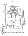
- FIG. 1 is a diagram showing structure of an engine system.
- This system includes a diesel engine (hereinafter referred to simply as "engine") 1 to which an exhaust emission control device as an embodiment of this invention is applied.
- engine diesel engine
- a fuel supply line 16 As shown in this figure, a fuel supply line 16, an intake passage 8 and an exhaust passage 20 are connected to each cylinder 2 of the engine 1.
- the line 16 includes a fuel injection unit, the passage 8 is the one through which fresh air is sent to a combustion chamber 4 when an intake valve 6 is opened, and the passage 20 is the one through which exhaust is sent from the combustion chamber 4 when an exhaust valve 18 is opened.
- a supercharger 14 In the intake passage 8, on the upstream side, a supercharger 14 is provided. An air cleaner (not shown) is connected to the passage 8 near the upstream end thereof. An intake throttle 10 and an inter-cooler 12 are also provided in the passage 8. The intake throttle 10 adjusts the flow passage area of the passage 8, and the inter-cooler 12 cools fresh air flowing through the passage 8 to increase volumetric efficiency.
- a NOx trap catalytic converter 22 In the exhaust passage 20, on the downstream side, a NOx trap catalytic converter 22 is provided.
- the catalytic converter 22 adsorbs NOx contained in exhaust when the exhaust air-fuel ratio is lean, namely greater than the stoichiometric air-fuel ratio, and releases and reduces the adsorbed NOx when the exhaust air-fuel ratio is rich and the exhaust contains unburned fuel (HC) and/or carbon monoxide (CO) serving as a reducing agent.
- the catalytic converter 22 has a known structure.
- EGR passage 24 From the exhaust passage 20 extends an EGR passage 24. At the forward end, the passage 24 is connected with the intake passage 8. An EGR cooler 26 and an EGR valve 28 are provided in the passage 24. The valve 28 is electrically connected to an electronic control unit (ECU) 50 and adjusts the flow passage area of the passage 24.
- ECU electronice control unit
- Combustion of fuel supplied through the line 16 causes a crank shaft 46 and a flywheel 48 to operate. After the combustion ends, exhaust is discharged into the exhaust passage 20 and sent to the catalytic converter 22.
- a NOx sensor 30 and an exhaust temperature sensor 34 are provided at appropriate positions upstream of the catalytic converter 22.
- the sensor 30 detects NOx concentration, or in other words, NOx amount upstream of the catalytic converter 22, from output voltage.
- the sensor 34 detects exhaust temperature T E in the passage 20.
- a NOx sensor 32 and a catalyst temperature sensor 36 are provided at appropriate positions downstream of the catalytic converter 22.
- the sensor 32 detects NOx amount downstream of the catalytic converter 22.
- the sensor 36 detects temperature Tc of the catalytic converter 22.
- an addition injector (supply means) 38 for supplying HC directly to the catalytic converter 22 is provided in the exhaust passage 20, at an appropriate position upstream of the catalytic converter 22, an addition injector (supply means) 38 for supplying HC directly to the catalytic converter 22 is provided.
- the injector 38 is connected with a pump 40 by a fuel addition line 39. Pressure in the line 39 is detected by a fuel pressure sensor (detection means) 42. Also the sensor 42 is electrically connected to the ECU 50.
- various sensors for detecting the operating state of the engine 1 such as a crank angle sensor 44 are electrically connected, in addition to the above-mentioned sensors 30, 32, 42, etc.
- various actuators such as an actuator for the injector 38 are electrically connected, in addition to the above-mentioned line 16, throttle 10, valve 28 and pump 40.
- the catalytic converter 22 adsorbs NOx contained in exhaust when it has an oxidizing atmosphere, and the ECU 50 carries out rich operation periodically.
- rich operation is carried out basically in the form of out-of-cylinder rich operation.
- HC forced by the pump 40 is supplied directly into exhaust through the injector 38 provided to the passage 20 to create conditions for rich operation.
- NOx is released and reduced.
- the ECU 50 includes an adsorption amount operation unit (OU) 52 and a combustion monitor unit (MU) 54.
- the MU 54 monitors the pressure in the line 39 on the basis of a detection signal from the sensor 42, and sends out a signal to the OU 52 when the HC supply pressure is almost zero.
- the HC supply pressure being almost zero is thought to indicate fuel leakage from the line 39, malfunction of the pump 40, etc.
- the OU 52 estimates the amount of NOx adsorbed by the catalytic converter 22. Specifically, first on the basis of output signals from the sensors 30, 32, NOx amount on the inlet side of the catalytic converter 22 and NOx amount on the outlet side thereof are obtained, and the amount of NOx adsorbed (referred to as “adsorption amount”) is calculated. Then, by subtracting the amount of NOx released and reduced by rich spike (referred to as “emission amount by rich spike”) from the calculated adsorption amount, the current adsorption amount is estimated.
- emission amount by rich spike basically the amount of NOx emitted by out-of-cylinder rich operation (referred to as "emission amount by out-of-cylinder rich operation"), namely the amount of NOx released and reduced by adding HC through the injector 38 is used.
- the emission amount by out-of-cylinder rich operation is obtained in advance, for example, from maps that are prepared depending on temperature T C of the catalytic converter 22. temperature T E of the passage 20, flow rate of exhaust SV, etc. and stored in the ECU 50.
- the emission amount by out-of-cylinder rich operation is set and used for estimating the current adsorption amount.
- an emission amount change unit 56 changes the emission amount by out-of-cylinder rich operation to zero to negate it in the estimation of the current adsorption amount.
- emission amount by post injection the amount of NOx emitted by post injection (referred to as “emission amount by post injection") is set on the basis of output values from the sensors 30, 32, 34, 36, and supplied to a rich spike change unit 58. Also the emission amount by post injection is obtained in advance from maps stored in the ECU 50.
- the change unit 58 chooses the emission amount by post injection. Then, the OU 52 estimates the current adsorption amount by subtracting the emission amount by post injection from the adsorption amount calculated on the basis of the output signals from the NOx sensors 30 and 32.
- the number of times that rich spike by post injection is performed and the accumulated time of rich spike by post injection are restricted to the number of times and the time which does not cause lubricating oil for the engine 1 to exceed its dilution limit. This is because the fuel supplied by post injection does not contribute to power generated by the engine 1, and hence, it can dilute lubricating oil held in a crank case along the cylindrical wall of the combustion chamber 4, etc. By providing the above restrictions, dilution of the lubricating oil is prevented.
- post injection is restricted to the engine 1 operation with medium load or lower. This is because when the engine is operating with high load, post injection leads to increase in NOx in exhaust. By providing this restriction, the number of times that post injection is performed is reduced, NOx contained in exhaust is reduced, and the necessity of immediately stopping the engine 1 can be avoided.
- the present embodiment is designed to perform alternative operation when the line 39, etc. are out of order (fail-safe).
- the sensor 42 for detecting the supply pressure in the line 39 is provided and the MU 54 monitors this pressure.
- this pressure is almost zero, that is, HC is not added to the catalytic converter 22, the OU 52 prohibits the calculation of the adsorption amount depending on out-of-cylinder rich operation.
- post injection is performed to regenerate the catalytic converter 22.
- the change unit 56 sets the emission amount by out-of-cylinder rich operation to zero. Hence, unlike the conventional case, incorrect estimation of the adsorption amount on the assumption that HC is property supplied is not continued. Thus, the accuracy of estimation of the adsorption amount improves, compared with the conventional case.
- alternative operation is performed by changing the way of rich spike from out-of-cylinder rich operation to in-cylinder rich operation.
- appropriate alternative operation can be performed using only out-of-cylinder rich operation.
- the emission amount by out-of-cylinder rich operation is used.
- the OU 52 obtains NOx amount on the inlet side of the catalytic converter 22 and NOx amount on the outlet side thereof on the basis of output signals from the sensors 30, 32, and calculates the adsorption amount. Then, when a rich spike instruction is given depending on signals from the sensors 30, 32, 34, 36, etc., the emission amount by out-of-cylinder rich operation is set referring to the maps.
- the MU 54 sends out a signal to the OU 52.
- the OU 52 sets a coefficient depending on the HC supply pressure detected.
- the coefficient is an index of what proportion of the fuel injected when the line 39, etc. are in order is actually injected into exhaust through the injector 38.
- the emission amount by out-of-cylinder rich operation set in advance referring to the maps, is corrected by being multiplied by this coefficient.
- the amount of NOx actually emitted (released and reduced) by out-of-cylinder rich operation is calculated this way, and the current adsorption amount is estimated.
- the rich spike cycle may be shortened, appropriate alternative operation is performed when HC fails to be added to the catalytic converter 22, so that increase in NOx is avoided. Consequently, also in this embodiment, reliability of the exhaust emission control device further improves (fail-safe).
- the exhaust emission control device can be a combination of FIGS. 2 and 3. Specifically, first, when the HC supply pressure detected by the sensor 42 is less than a desired supply pressure, the OU 52 calculates the amount of NOx actually emitted (released and reduced), by correcting the emission amount by out-of-cylinder rich operation, using the coefficient, and estimates the current adsorption amount.
- the OU 52 uses the emission amount by out-of-cylinder rich operation which has been set to zero by the change unit 56. After this, as long as the HC supply pressure remains almost zero, when a rich spike instruction is given, post injection is performed and the current adsorption amount is estimated by subtracting the emission amount by post injection. In this embodiment, more appropriate alternative operation is performed.
- the MU 54 monitors the value detected by the fuel pressure sensor 42
- the MU 54 may monitor the value detected by the flow rate sensor.
- the change unit 58 changes out-of-cylinder rich operation to post injection
- out-of-cylinder rich operation may be changed to in-cylinder rich operation using CO emitted due to imperfect combustion caused by recirculating a large amount of exhaust and utilizing the valve 28 and the throttle 10.
- the engine is preferably a diesel engine but not limited to it.
- the exhaust emission control device according to this invention is applicable to all the engine systems that have a NOx trap catalytic converter in an exhaust passage and are capable of rich operation.
Landscapes
- Engineering & Computer Science (AREA)
- Chemical & Material Sciences (AREA)
- Combustion & Propulsion (AREA)
- Mechanical Engineering (AREA)
- General Engineering & Computer Science (AREA)
- Chemical Kinetics & Catalysis (AREA)
- Health & Medical Sciences (AREA)
- Toxicology (AREA)
- Exhaust Gas After Treatment (AREA)
- Exhaust Gas Treatment By Means Of Catalyst (AREA)
- Electrical Control Of Air Or Fuel Supplied To Internal-Combustion Engine (AREA)
Applications Claiming Priority (1)
| Application Number | Priority Date | Filing Date | Title |
|---|---|---|---|
| JP2004320847A JP2006132392A (ja) | 2004-11-04 | 2004-11-04 | 内燃機関の排気浄化装置 |
Publications (1)
| Publication Number | Publication Date |
|---|---|
| EP1655461A1 true EP1655461A1 (de) | 2006-05-10 |
Family
ID=35658964
Family Applications (1)
| Application Number | Title | Priority Date | Filing Date |
|---|---|---|---|
| EP05023482A Withdrawn EP1655461A1 (de) | 2004-11-04 | 2005-10-27 | Einrichtung zur Regelung der Abgasemissionen einer Brennkraftmaschine |
Country Status (5)
| Country | Link |
|---|---|
| US (1) | US20060112681A1 (de) |
| EP (1) | EP1655461A1 (de) |
| JP (1) | JP2006132392A (de) |
| KR (1) | KR100649401B1 (de) |
| CN (1) | CN1769651A (de) |
Cited By (2)
| Publication number | Priority date | Publication date | Assignee | Title |
|---|---|---|---|---|
| FR2928413A1 (fr) * | 2008-03-10 | 2009-09-11 | Renault Sas | Procede de gestion du fonctionnement d'au moins un convertisseur catalytique pour moteur a combustion interne |
| CN101573513B (zh) * | 2006-12-21 | 2012-05-23 | 丰田自动车株式会社 | 用于内燃机的废气控制装置和方法 |
Families Citing this family (8)
| Publication number | Priority date | Publication date | Assignee | Title |
|---|---|---|---|---|
| JP2006090238A (ja) * | 2004-09-24 | 2006-04-06 | Mitsubishi Fuso Truck & Bus Corp | NOx吸蔵触媒の吸蔵量推定装置及び吸蔵量推定方法 |
| JP4692436B2 (ja) * | 2006-08-04 | 2011-06-01 | トヨタ自動車株式会社 | 内燃機関の排気浄化システム |
| JP2008297969A (ja) * | 2007-05-31 | 2008-12-11 | Denso Corp | 内燃機関の排気浄化装置 |
| DE102008042784B4 (de) * | 2008-10-13 | 2016-01-28 | Ford Global Technologies, Llc | Verfahren zum Betreiben einer direkteinspritzenden Brennkraftmaschine mit mindestens einem Abgasnachbehandlungssystem |
| WO2011033620A1 (ja) * | 2009-09-16 | 2011-03-24 | トヨタ自動車株式会社 | 内燃機関の排気浄化装置及び排気浄化方法 |
| DE102011076073B4 (de) | 2011-05-18 | 2013-01-03 | Mtu Friedrichshafen Gmbh | Verfahren zur Steuerung und Regelung eines Brennkraftmaschinen-Generator-Systems, Einrichtung zur Steuerung und Regelung sowie Brennkraftmaschinen-Generator-System und Land- oder Wasserfahrzeug oder stationäre Anlage zur Erzeugung elektrischer Energie |
| JP6036565B2 (ja) * | 2013-06-14 | 2016-11-30 | 株式会社デンソー | 電子制御装置 |
| DE102016209566A1 (de) * | 2016-06-01 | 2017-12-07 | Ford Global Technologies, Llc | Steuern einer Stickoxidemission im Abgas einer Brennkraftmaschine |
Citations (7)
| Publication number | Priority date | Publication date | Assignee | Title |
|---|---|---|---|---|
| WO2001025601A1 (de) * | 1999-10-01 | 2001-04-12 | Robert Bosch Gmbh | Vorrichtung zum nachbehandeln von abgasen einer brennkraftmaschine |
| EP1176292A1 (de) * | 2000-07-24 | 2002-01-30 | Toyota Jidosha Kabushiki Kaisha | Vorrichtung zur Abgasreinigung für eine Brennkraftmaschine |
| JP2002242780A (ja) | 2001-02-16 | 2002-08-28 | Toyota Motor Corp | 内燃機関の燃料供給装置 |
| EP1291498A2 (de) * | 2001-09-11 | 2003-03-12 | Toyota Jidosha Kabushiki Kaisha | Abgasemissionssteuerungssystem für eine Brennkraftmaschine |
| FR2832184A1 (fr) * | 2001-11-12 | 2003-05-16 | Toyota Motor Co Ltd | Systeme et procede de commande d'emission d'un moteur a combustion interne |
| EP1331373A2 (de) * | 2002-01-29 | 2003-07-30 | Toyota Jidosha Kabushiki Kaisha | Versorgungssystem eines Reduktionsmittels |
| US20040154288A1 (en) * | 1999-01-21 | 2004-08-12 | Mitsubishi Jidosha Kogyo Kabushiki Kaisha | Exhaust gas purifier for use in internal combustion engine |
Family Cites Families (11)
| Publication number | Priority date | Publication date | Assignee | Title |
|---|---|---|---|---|
| JP3478135B2 (ja) * | 1998-08-06 | 2003-12-15 | トヨタ自動車株式会社 | 内燃機関の排気浄化装置 |
| JP2000297631A (ja) * | 1999-04-09 | 2000-10-24 | Toyota Motor Corp | 内燃機関の排気浄化装置 |
| JP3552653B2 (ja) * | 2000-07-24 | 2004-08-11 | トヨタ自動車株式会社 | 内燃機関の還元剤供給装置の診断処理装置 |
| JP2002081311A (ja) * | 2000-09-05 | 2002-03-22 | Toyota Motor Corp | 内燃機関の排気浄化装置 |
| JP3576504B2 (ja) * | 2001-05-24 | 2004-10-13 | 日野自動車株式会社 | 排気浄化装置 |
| JP3788350B2 (ja) * | 2002-01-07 | 2006-06-21 | 日産自動車株式会社 | 内燃機関の排気浄化装置 |
| JP3912289B2 (ja) * | 2003-01-10 | 2007-05-09 | 日産自動車株式会社 | パティキュレートフィルタの再生装置及びエンジンの排気ガス浄化装置 |
| JP3894125B2 (ja) * | 2003-01-28 | 2007-03-14 | 日産自動車株式会社 | 内燃機関の排気浄化装置 |
| JP2005048746A (ja) * | 2003-07-31 | 2005-02-24 | Nissan Motor Co Ltd | 内燃機関の燃焼制御装置 |
| JP3718209B2 (ja) * | 2003-10-03 | 2005-11-24 | 日産ディーゼル工業株式会社 | エンジンの排気浄化装置 |
| FR2866927B1 (fr) * | 2004-02-27 | 2008-03-07 | Peugeot Citroen Automobiles Sa | Systeme d'aide a la regeneration de moyens de depollution |
-
2004
- 2004-11-04 JP JP2004320847A patent/JP2006132392A/ja active Pending
-
2005
- 2005-10-27 EP EP05023482A patent/EP1655461A1/de not_active Withdrawn
- 2005-10-27 KR KR1020050101653A patent/KR100649401B1/ko not_active IP Right Cessation
- 2005-11-01 US US11/264,359 patent/US20060112681A1/en not_active Abandoned
- 2005-11-04 CN CNA2005101155496A patent/CN1769651A/zh active Pending
Patent Citations (7)
| Publication number | Priority date | Publication date | Assignee | Title |
|---|---|---|---|---|
| US20040154288A1 (en) * | 1999-01-21 | 2004-08-12 | Mitsubishi Jidosha Kogyo Kabushiki Kaisha | Exhaust gas purifier for use in internal combustion engine |
| WO2001025601A1 (de) * | 1999-10-01 | 2001-04-12 | Robert Bosch Gmbh | Vorrichtung zum nachbehandeln von abgasen einer brennkraftmaschine |
| EP1176292A1 (de) * | 2000-07-24 | 2002-01-30 | Toyota Jidosha Kabushiki Kaisha | Vorrichtung zur Abgasreinigung für eine Brennkraftmaschine |
| JP2002242780A (ja) | 2001-02-16 | 2002-08-28 | Toyota Motor Corp | 内燃機関の燃料供給装置 |
| EP1291498A2 (de) * | 2001-09-11 | 2003-03-12 | Toyota Jidosha Kabushiki Kaisha | Abgasemissionssteuerungssystem für eine Brennkraftmaschine |
| FR2832184A1 (fr) * | 2001-11-12 | 2003-05-16 | Toyota Motor Co Ltd | Systeme et procede de commande d'emission d'un moteur a combustion interne |
| EP1331373A2 (de) * | 2002-01-29 | 2003-07-30 | Toyota Jidosha Kabushiki Kaisha | Versorgungssystem eines Reduktionsmittels |
Cited By (4)
| Publication number | Priority date | Publication date | Assignee | Title |
|---|---|---|---|---|
| CN101573513B (zh) * | 2006-12-21 | 2012-05-23 | 丰田自动车株式会社 | 用于内燃机的废气控制装置和方法 |
| FR2928413A1 (fr) * | 2008-03-10 | 2009-09-11 | Renault Sas | Procede de gestion du fonctionnement d'au moins un convertisseur catalytique pour moteur a combustion interne |
| WO2009115759A2 (fr) * | 2008-03-10 | 2009-09-24 | Renault S.A.S | Procede de gestion du fonctionnement d'au moins un convertisseur catalytique pour moteur a combustion interne |
| WO2009115759A3 (fr) * | 2008-03-10 | 2009-12-03 | Renault S.A.S | Procede de gestion du fonctionnement d'au moins un convertisseur catalytique pour moteur a combustion interne |
Also Published As
| Publication number | Publication date |
|---|---|
| JP2006132392A (ja) | 2006-05-25 |
| US20060112681A1 (en) | 2006-06-01 |
| KR100649401B1 (ko) | 2006-11-27 |
| CN1769651A (zh) | 2006-05-10 |
| KR20060052246A (ko) | 2006-05-19 |
Similar Documents
| Publication | Publication Date | Title |
|---|---|---|
| EP1655461A1 (de) | Einrichtung zur Regelung der Abgasemissionen einer Brennkraftmaschine | |
| US10174695B2 (en) | Control device for internal combustion engine | |
| US8875488B2 (en) | Internal combustion engine | |
| EP3006689B1 (de) | Fehlerdiagnosevorrichtung für eine abgasreinigungsvorrichtung | |
| US8857161B2 (en) | Exhaust gas purification apparatus and exhaust gas purification method for an internal combustion engine | |
| US20070277509A1 (en) | Exhaust gas purification system and method of purifying exhaust gas | |
| JP2008002309A (ja) | 内燃機関の排気浄化装置 | |
| US7963101B2 (en) | Exhaust gas purifying device for an internal combustion engine | |
| JP2008128114A (ja) | 内燃機関の排気絞り弁故障診断装置 | |
| US20050193724A1 (en) | Oxygen-enriched feedgas for reformer in emissions control system | |
| JP5039367B2 (ja) | 内燃機関の排気浄化装置 | |
| US7950225B2 (en) | Exhaust control system for an internal combustion engine | |
| US20190293617A1 (en) | Method for estimating exhaust gas state of engine, method for determining abnormality of catalyst, and catalyst abnormality determination device for an engine | |
| US6907858B2 (en) | Engine fuel injection control system | |
| JP3632570B2 (ja) | 内燃機関の排気浄化装置 | |
| US20070006575A1 (en) | Exhaust gas purifying device for an internal combustion engine | |
| JP4352651B2 (ja) | 内燃機関の異常判定装置 | |
| JP5831162B2 (ja) | NOxセンサの異常診断方法、NOxセンサの異常診断システム、及び内燃機関 | |
| US20190292961A1 (en) | Method for estimating exhaust gas state of engine, method for determining abnormality of catalyst, and catalyst abnormality determination device for an engine | |
| JP4893493B2 (ja) | 内燃機関の排気浄化装置 | |
| JP2013068210A (ja) | エンジンの制御装置 | |
| JP7217867B2 (ja) | 排気ガス浄化装置の診断装置 | |
| JP4539466B2 (ja) | 内燃機関の排気浄化システム | |
| JP2008002398A (ja) | 内燃機関の排気浄化装置 | |
| JP2013217323A (ja) | 内燃機関の排気浄化装置 |
Legal Events
| Date | Code | Title | Description |
|---|---|---|---|
| PUAI | Public reference made under article 153(3) epc to a published international application that has entered the european phase |
Free format text: ORIGINAL CODE: 0009012 |
|
| AK | Designated contracting states |
Kind code of ref document: A1 Designated state(s): AT BE BG CH CY CZ DE DK EE ES FI FR GB GR HU IE IS IT LI LT LU LV MC NL PL PT RO SE SI SK TR |
|
| AX | Request for extension of the european patent |
Extension state: AL BA HR MK YU |
|
| 17P | Request for examination filed |
Effective date: 20061026 |
|
| 17Q | First examination report despatched |
Effective date: 20061208 |
|
| AKX | Designation fees paid |
Designated state(s): DE PT |
|
| STAA | Information on the status of an ep patent application or granted ep patent |
Free format text: STATUS: THE APPLICATION IS DEEMED TO BE WITHDRAWN |
|
| 18D | Application deemed to be withdrawn |
Effective date: 20090825 |