EP1653896B1 - Sonde endoscopique laser a eclairage coaxial - Google Patents
Sonde endoscopique laser a eclairage coaxial Download PDFInfo
- Publication number
- EP1653896B1 EP1653896B1 EP04786120A EP04786120A EP1653896B1 EP 1653896 B1 EP1653896 B1 EP 1653896B1 EP 04786120 A EP04786120 A EP 04786120A EP 04786120 A EP04786120 A EP 04786120A EP 1653896 B1 EP1653896 B1 EP 1653896B1
- Authority
- EP
- European Patent Office
- Prior art keywords
- illumination
- laser
- light
- illumination light
- output
- Prior art date
- Legal status (The legal status is an assumption and is not a legal conclusion. Google has not performed a legal analysis and makes no representation as to the accuracy of the status listed.)
- Not-in-force
Links
- 239000000523 sample Substances 0.000 title description 25
- 238000005286 illumination Methods 0.000 claims description 202
- 239000013307 optical fiber Substances 0.000 claims description 74
- 230000003287 optical effect Effects 0.000 claims description 17
- 238000011282 treatment Methods 0.000 claims description 15
- 230000003595 spectral effect Effects 0.000 claims description 9
- 239000000835 fiber Substances 0.000 description 48
- 238000013532 laser treatment Methods 0.000 description 19
- 230000001427 coherent effect Effects 0.000 description 16
- 238000000034 method Methods 0.000 description 15
- 206010034972 Photosensitivity reaction Diseases 0.000 description 10
- 208000007578 phototoxic dermatitis Diseases 0.000 description 10
- 231100000018 phototoxicity Toxicity 0.000 description 10
- 238000001356 surgical procedure Methods 0.000 description 10
- 230000004075 alteration Effects 0.000 description 7
- 230000008878 coupling Effects 0.000 description 7
- 238000010168 coupling process Methods 0.000 description 7
- 238000005859 coupling reaction Methods 0.000 description 7
- 208000014674 injury Diseases 0.000 description 7
- 208000027418 Wounds and injury Diseases 0.000 description 6
- 230000006378 damage Effects 0.000 description 6
- 238000010586 diagram Methods 0.000 description 6
- 229910052724 xenon Inorganic materials 0.000 description 6
- FHNFHKCVQCLJFQ-UHFFFAOYSA-N xenon atom Chemical compound [Xe] FHNFHKCVQCLJFQ-UHFFFAOYSA-N 0.000 description 6
- 230000013011 mating Effects 0.000 description 5
- 230000008859 change Effects 0.000 description 4
- 230000004913 activation Effects 0.000 description 3
- 230000005540 biological transmission Effects 0.000 description 3
- 238000001914 filtration Methods 0.000 description 3
- 230000033001 locomotion Effects 0.000 description 3
- 229910052751 metal Inorganic materials 0.000 description 3
- 239000002184 metal Substances 0.000 description 3
- 238000004382 potting Methods 0.000 description 3
- 230000009467 reduction Effects 0.000 description 3
- 238000010521 absorption reaction Methods 0.000 description 2
- 239000006117 anti-reflective coating Substances 0.000 description 2
- 239000000919 ceramic Substances 0.000 description 2
- 239000002131 composite material Substances 0.000 description 2
- 238000005516 engineering process Methods 0.000 description 2
- ORUIBWPALBXDOA-UHFFFAOYSA-L magnesium fluoride Chemical compound [F-].[F-].[Mg+2] ORUIBWPALBXDOA-UHFFFAOYSA-L 0.000 description 2
- 229910001635 magnesium fluoride Inorganic materials 0.000 description 2
- 230000014759 maintenance of location Effects 0.000 description 2
- 239000000463 material Substances 0.000 description 2
- 150000002739 metals Chemical class 0.000 description 2
- 239000004033 plastic Substances 0.000 description 2
- 229920003023 plastic Polymers 0.000 description 2
- 238000009877 rendering Methods 0.000 description 2
- 230000002207 retinal effect Effects 0.000 description 2
- 206010010071 Coma Diseases 0.000 description 1
- 239000000853 adhesive Substances 0.000 description 1
- 230000001070 adhesive effect Effects 0.000 description 1
- 230000002411 adverse Effects 0.000 description 1
- 239000011093 chipboard Substances 0.000 description 1
- 239000003086 colorant Substances 0.000 description 1
- 150000001875 compounds Chemical class 0.000 description 1
- 238000013461 design Methods 0.000 description 1
- 238000003745 diagnosis Methods 0.000 description 1
- 201000010099 disease Diseases 0.000 description 1
- 208000037265 diseases, disorders, signs and symptoms Diseases 0.000 description 1
- 239000000975 dye Substances 0.000 description 1
- 230000000694 effects Effects 0.000 description 1
- 230000008030 elimination Effects 0.000 description 1
- 238000003379 elimination reaction Methods 0.000 description 1
- 230000005284 excitation Effects 0.000 description 1
- 239000011521 glass Substances 0.000 description 1
- 238000010438 heat treatment Methods 0.000 description 1
- 230000010354 integration Effects 0.000 description 1
- 238000005259 measurement Methods 0.000 description 1
- 230000007246 mechanism Effects 0.000 description 1
- 230000003278 mimic effect Effects 0.000 description 1
- 238000012986 modification Methods 0.000 description 1
- 230000004048 modification Effects 0.000 description 1
- 210000000056 organ Anatomy 0.000 description 1
- 231100000760 phototoxic Toxicity 0.000 description 1
- 238000012545 processing Methods 0.000 description 1
- 230000004044 response Effects 0.000 description 1
- 238000007493 shaping process Methods 0.000 description 1
- 208000017520 skin disease Diseases 0.000 description 1
- 238000001228 spectrum Methods 0.000 description 1
- 230000008733 trauma Effects 0.000 description 1
- 238000001429 visible spectrum Methods 0.000 description 1
- 238000012800 visualization Methods 0.000 description 1
Images


Classifications
-
- A—HUMAN NECESSITIES
- A61—MEDICAL OR VETERINARY SCIENCE; HYGIENE
- A61B—DIAGNOSIS; SURGERY; IDENTIFICATION
- A61B18/00—Surgical instruments, devices or methods for transferring non-mechanical forms of energy to or from the body
- A61B18/18—Surgical instruments, devices or methods for transferring non-mechanical forms of energy to or from the body by applying electromagnetic radiation, e.g. microwaves
- A61B18/20—Surgical instruments, devices or methods for transferring non-mechanical forms of energy to or from the body by applying electromagnetic radiation, e.g. microwaves using laser
- A61B18/22—Surgical instruments, devices or methods for transferring non-mechanical forms of energy to or from the body by applying electromagnetic radiation, e.g. microwaves using laser the beam being directed along or through a flexible conduit, e.g. an optical fibre; Couplings or hand-pieces therefor
-
- A—HUMAN NECESSITIES
- A61—MEDICAL OR VETERINARY SCIENCE; HYGIENE
- A61B—DIAGNOSIS; SURGERY; IDENTIFICATION
- A61B1/00—Instruments for performing medical examinations of the interior of cavities or tubes of the body by visual or photographical inspection, e.g. endoscopes; Illuminating arrangements therefor
- A61B1/06—Instruments for performing medical examinations of the interior of cavities or tubes of the body by visual or photographical inspection, e.g. endoscopes; Illuminating arrangements therefor with illuminating arrangements
- A61B1/0661—Endoscope light sources
-
- A—HUMAN NECESSITIES
- A61—MEDICAL OR VETERINARY SCIENCE; HYGIENE
- A61F—FILTERS IMPLANTABLE INTO BLOOD VESSELS; PROSTHESES; DEVICES PROVIDING PATENCY TO, OR PREVENTING COLLAPSING OF, TUBULAR STRUCTURES OF THE BODY, e.g. STENTS; ORTHOPAEDIC, NURSING OR CONTRACEPTIVE DEVICES; FOMENTATION; TREATMENT OR PROTECTION OF EYES OR EARS; BANDAGES, DRESSINGS OR ABSORBENT PADS; FIRST-AID KITS
- A61F9/00—Methods or devices for treatment of the eyes; Devices for putting-in contact lenses; Devices to correct squinting; Apparatus to guide the blind; Protective devices for the eyes, carried on the body or in the hand
- A61F9/007—Methods or devices for eye surgery
- A61F9/008—Methods or devices for eye surgery using laser
-
- G—PHYSICS
- G02—OPTICS
- G02B—OPTICAL ELEMENTS, SYSTEMS OR APPARATUS
- G02B6/00—Light guides; Structural details of arrangements comprising light guides and other optical elements, e.g. couplings
- G02B6/24—Coupling light guides
- G02B6/36—Mechanical coupling means
- G02B6/38—Mechanical coupling means having fibre to fibre mating means
- G02B6/3807—Dismountable connectors, i.e. comprising plugs
- G02B6/3897—Connectors fixed to housings, casing, frames or circuit boards
-
- A—HUMAN NECESSITIES
- A61—MEDICAL OR VETERINARY SCIENCE; HYGIENE
- A61B—DIAGNOSIS; SURGERY; IDENTIFICATION
- A61B18/00—Surgical instruments, devices or methods for transferring non-mechanical forms of energy to or from the body
- A61B18/18—Surgical instruments, devices or methods for transferring non-mechanical forms of energy to or from the body by applying electromagnetic radiation, e.g. microwaves
- A61B18/20—Surgical instruments, devices or methods for transferring non-mechanical forms of energy to or from the body by applying electromagnetic radiation, e.g. microwaves using laser
- A61B2018/2015—Miscellaneous features
- A61B2018/2025—Miscellaneous features with a pilot laser
-
- A—HUMAN NECESSITIES
- A61—MEDICAL OR VETERINARY SCIENCE; HYGIENE
- A61B—DIAGNOSIS; SURGERY; IDENTIFICATION
- A61B90/00—Instruments, implements or accessories specially adapted for surgery or diagnosis and not covered by any of the groups A61B1/00 - A61B50/00, e.g. for luxation treatment or for protecting wound edges
- A61B90/30—Devices for illuminating a surgical field, the devices having an interrelation with other surgical devices or with a surgical procedure
- A61B2090/306—Devices for illuminating a surgical field, the devices having an interrelation with other surgical devices or with a surgical procedure using optical fibres
-
- A—HUMAN NECESSITIES
- A61—MEDICAL OR VETERINARY SCIENCE; HYGIENE
- A61F—FILTERS IMPLANTABLE INTO BLOOD VESSELS; PROSTHESES; DEVICES PROVIDING PATENCY TO, OR PREVENTING COLLAPSING OF, TUBULAR STRUCTURES OF THE BODY, e.g. STENTS; ORTHOPAEDIC, NURSING OR CONTRACEPTIVE DEVICES; FOMENTATION; TREATMENT OR PROTECTION OF EYES OR EARS; BANDAGES, DRESSINGS OR ABSORBENT PADS; FIRST-AID KITS
- A61F9/00—Methods or devices for treatment of the eyes; Devices for putting-in contact lenses; Devices to correct squinting; Apparatus to guide the blind; Protective devices for the eyes, carried on the body or in the hand
- A61F9/007—Methods or devices for eye surgery
- A61F9/008—Methods or devices for eye surgery using laser
- A61F2009/00861—Methods or devices for eye surgery using laser adapted for treatment at a particular location
- A61F2009/00863—Retina
-
- A—HUMAN NECESSITIES
- A61—MEDICAL OR VETERINARY SCIENCE; HYGIENE
- A61F—FILTERS IMPLANTABLE INTO BLOOD VESSELS; PROSTHESES; DEVICES PROVIDING PATENCY TO, OR PREVENTING COLLAPSING OF, TUBULAR STRUCTURES OF THE BODY, e.g. STENTS; ORTHOPAEDIC, NURSING OR CONTRACEPTIVE DEVICES; FOMENTATION; TREATMENT OR PROTECTION OF EYES OR EARS; BANDAGES, DRESSINGS OR ABSORBENT PADS; FIRST-AID KITS
- A61F9/00—Methods or devices for treatment of the eyes; Devices for putting-in contact lenses; Devices to correct squinting; Apparatus to guide the blind; Protective devices for the eyes, carried on the body or in the hand
- A61F9/007—Methods or devices for eye surgery
- A61F9/008—Methods or devices for eye surgery using laser
- A61F2009/00861—Methods or devices for eye surgery using laser adapted for treatment at a particular location
- A61F2009/00874—Vitreous
Definitions
- the invention refers to an illumination and laser source according to the preamble of claim 1.
- the art of the present invention relates to fiberoptic endoscopic probes for vitreoretinal surgery in general and more particularly to an apparatus and method for delivery of both broad spectrum illumination and coherent laser treatment pulses through a common optical fiber.
- Prior art vitreoretinal surgical procedure utilizes discrete and separate optical fibers for the delivery of typically non-coherent light for illumination and coherent laser beam light for surgical treatment of tissues.
- prior art "illuminated laser probes" of various configurations have been developed, they all utilize separate optical fiber or fibers for the non-coherent illumination stream and the coherent laser delivery.
- the aforesaid fibers are typically arranged side by side inside of a common needle lumen.
- An embodiment of this prior art technology is found in US 5,323,766 A . This prior art technology requires a larger or more than one incision in order to introduce illumination and laser treatment light into the eye or other structure, thereby generating greater trauma to the surgical site.
- Prior art devices typically utilize a laser deliver core optical fiber diameter of typically 200 to 300 ⁇ m since said diameter provides the surgical laser burn spot size most commonly desired by the surgeon.
- the aforesaid prior art devices have been unable to provide sufficient surgically useful illumination (non-coherent white light) power through such a small fiber, primarily due to the prior art's inability to focus said non-coherent surgically useful light onto such a small spot size.
- none of the prior art devices have combined the aforesaid surgically useful illumination and laser treatment light and transmitted through a single fiber, especially of the aforesaid small size.
- Prior art illumination light sources typically require a minimum aggregate optical fiber core area equivalent to a fiber diameter of approximately 500 ⁇ m in order to deliver sufficient illuminating light to be considered useful by the surgeon.
- a fundamental prior art limitation with utilization of smaller light fibers for illumination is the size of the focus spot in the light source itself.
- Ophthalmic surgical illumination devices for use with optical fibers are found in the prior art and have been manufactured by numerous companies for years.
- One of many such devices is described in U.S. Patent #4,757,426 issued to Scheller, et al. on July 12, 1988 , Entitled “ Illumination System for Fiber Optic Lighting Instruments ".
- One of the most widely used illumination devices is the "Millennium” which is manufactured by Bausch and Lomb®.
- Other manufacturers are Alcon® with the “Accurus” and Grieshaber® with the "GLS 150".
- US 6,485,414 B1 describes a mini-endoscope system having an endoscope body in which a fiber light transport element is arranged to convey light from a laser diode illumination source to the distal end of the endoscope body, where the light is radiated to illuminate a object.
- the laser diode illumination source comprises laser diodes generating light of different colours and optionally a laser diode generating diagnostic laser light.
- the light beams emanating from the laser diodes is combined by beam splitters onto the fiber light transport element.
- US 6,519,485 B2 discloses a system for assessing organ function which comprises four laser diodes coupled via a coupling assembly into a 200 ⁇ m optical fiber with an output which is used for spectral assessment.
- the wavelengths of said laser diodes have peaks at 735, 760, 805, and 890 nm.
- US 6,069,689 A discloses an apparatus for diagnosis of skin disease comprising a excitation laser light source and a white light source which are joined together by an optical coupler that allows light from either source to be transmitted via the same optical fiber bundle.
- the disease site is illuminated sequentially by only one of the light sources at a time.
- the white light is reflected by a mirror onto the fiber bundle whereas the laser light is directed through a 2mm hole in the mirror onto the fiber bundle.
- US 5,313,070 A discloses a method of illuminating checks in a check-processing system in which an emission from a xenon lamp is fed to a flat infrared reflector for IR dumping.
- the xenon lamp comprises a sheet-metal box having an aperture through which light is projected. Lenses are moved toward or away from fiber bundles, substantially parallel with the light beam, in order to defocus and thereby control illumination intensity.
- an illumination and laser source which is capable of transmitting both illumination (non-coherent) and laser (coherent) treatment light through a single optical fiber of sufficiently small diameter that said fiber may be used for laser treatment, especially in eye surgical or ophthalmic applications.
- Another object of the present invention is to provide an illumination and laser source which provides both a surgically useful illumination (non-coherent) output and a combined laser (coherent) output.
- Another object of the present invention is to provide an illumination and laser source with an illumination intensity control which is usable by the surgeon to control illumination intensity without affecting laser output power or laser beam spot size characteristics or illumination spectral content.
- the apparatus first comprises a non-coherent light source (coherent in an alternative embodiment) capable of coupling sufficient illumination light into an optical fiber with a core diameter suitable for vitreoretinal laser treatment light delivery. That is, to provide a volume of light to the surgical site which is sufficient for illumination of the surgical procedure.
- said core fiber diameter is typically 200 to 300 ⁇ m since said diameter provides the surgical laser burn spot size most commonly desired by the surgeon.
- the aforesaid optical fiber is typically a multi-mode stepped index fiber in a preferred embodiment. Alternative embodiments may vary the type and size of the optical fiber without departing from the scope of the present art.
- a light source is utilized which is capable of using 250 ⁇ m (or smaller) optical fibers while still providing similar surgically useful lumen output to current 750 ⁇ m fiber sources (typically 10-12 lumens).
- the source output aperture of the present invention in a preferred embodiment is at least 0.5 na (numerical aperture). Alternative embodiments may vary this numerical aperture without departing from the scope of the present invention.
- the color of the light delivered by the present invention appears white despite the light power output or intensity. Also, the output intensity is capable of reduction without significantly affecting the color, aperture, or homogeneity of the light.
- the output bandwidth of the aforesaid light is substantially limited to the visible spectrum, that is both UV and IR light are minimized.
- An option for user selectable limitations (separate from the UV and IR limitations) in the output spectrum is provided. Apparatus conformance to relevant safety standards is also provided.
- the art of the present invention utilizes a small geometry arc lamp which is capable of focusing to an extremely small illumination spot size due to its extremely small plasma ball.
- This focusing attribute allows for efficient coupling of illumination light into an optical fiber of 100 to 300 ⁇ m core diameter which is typically utilized for laser treatment light delivery.
- Utilization of the aforesaid preferred embodiment allows for up to 40 milliwatts of illumination light to be delivered by a fiber previously considered too small to be an efficient illumination light source.
- the aforesaid present art light source includes an input aperture or connector for the attachment of a laser coupling fiber.
- the aforesaid aperture attachment is somewhat similar to the method by which a treatment laser is attached with an ophthalmic slit lamp. That is, via a fiber optic pigtail typically equipped with a mechanical output connector such as an exi sma.
- dichroic optics and/or other optical path design techniques are used to coaxially couple a treatment laser beam into the illumination optical path, and into an endoscopic probe optical fiber. That is, with the aforesaid coupling arrangement (using a single fiber), the present art apparatus and method allows a unique single and smaller optical fiber to be utilized for both illumination and laser treatment purposes.
- the art of the present invention further provides a new generation of vitreo-retinal endoscopic instrumentation which utilizes the prior art space occupied by larger illumination fibers and is also capable of providing such in a smaller cross-sectional fiber bundle.
- the present art accepts laser light from various surgical laser sources, mixes said laser light with illumination light, and launches both down a single fiber.
- Laser output aperture is minimized and the laser light is not substantially affected by the illumination dimming or other spectral output limiting.
- An aiming beam is visible within the illumination output pattern.
- Unique to the present art is a shadow appearance in the output light cone which indicates the location of laser treatment upon activation of a laser light source. Power losses through the system are also minimized.
- the laser mixing method does not significantly affect illumination when not in use (i.e. color, aperture, or homogeneity).
- Another unique feature of the present art invention is the ability to change the angular light output from an endoscopic probe coupled with the aforesaid coaxial optical fiber by actively controlling the focus characteristics of the light source. That is, prior art light sources have a fixed numerical aperture focus configuration which is typically designed to fill the full acceptance cone of the mating optical illumination fiber.
- the present art invention further comprises and utilizes surgeon controlled condensing optics to provide a variable focused light output from the endoscopic probe and efficient coupling into different fiber types. This is especially useful for coupling with optical fibers having different numerical aperture requirements.
- the present art invention further represents a novel apparatus and method for providing the ophthalmic surgeon with graphical photoxicity risk information in a clear and easy to understand manner.
- it is comprised of an inexpensive card that is removably attached to the control panel of a surgical light source in order to show the relationship between the output intensity of the light source and the likelihood of photic injury.
- an integral optical power meter which is in a preferred embodiment, capable of measuring the laser power output emanating from the fiber optic.
- Alternative embodiments of said laser power meter also measure the illumination power intensity.
- the present art utilizes a 75 watt xenon arc lamp for its high luminance illumination (light density), greater than 6000 °K color temperature, and greater than 95 color rendering index.
- the xenon arc lamp further provides an extremely small point light source which allows for a smaller output illumination beam diameter.
- Unique to the present lamp source is a mount which allows for replacement of the lamp and yet retains the location of the plasma ball of said source precisely at a predetermined location within the optical center of the apparatus.
- a classic spherical reflector and two lens light collection layout is utilized rather than other lower part count layouts, such as using an elliptical reflector or a combination of a parabolic reflector and lens.
- Light that is incident on the reflector is reflected back to the lamp.
- a first achromatic lens collimates light from the source and the upside down or inverted image.
- a second achromatic lens is located coaxial to the first lens and focuses the light at its focal point.
- the optical fiber is located at the focal point of the second lens.
- the aforesaid reflectors are preferably spherical rather than parabolic in order to reflect illumination light in the same form as sourced from the arc lamp.
- Output dimming of the present art illumination is accomplished by steering the first (collimating) or penultimate lens in a fashion that does not change the lens numerical aperture or introduce shadow artifacts into the beam.
- a control knob allows the user to select the desired illumination level by rotating the knob.
- the output optical fiber connector is uniquely configured to provide the precise positioning required while reducing cost.
- a precise connector end is combined with an integral retention thread to reduce parts cost and assembly time.
- An optional groove or recess is placed on a second version of the connector to provide for sensing the difference between illumination only and laser compatible output fibers. Placement of a smooth diameter connector into the output activates a switch which will allow the laser power to be mixed. Either the lack of a connector or the groove under the switch will cause the switch to not activate and the laser power will not be mixed in.
- laser light is delivered to the system via a preferably 50 ⁇ m optical fiber or equivalent.
- Laser light exiting the delivery fiber is preferably collimated using a 16 mm focal length achromatic lens or equivalent.
- a steering mirror reflects the collimated laser light into the center of the illumination axis. This results in the output of the fiber having a cone of white light with a shadow in the center nearly filled with the laser aiming beam (treatment beam during treatment). That is, the laser provides an aiming beam, typically red, when not fully activated for treatment and a treatment beam, typically green, when fully activated. Without the shadow caused by the steering mirror the aiming beam would be entirely washed out or imperceptible except at very low illumination levels.
- a coaxial laser and illumination apparatus which heretofore has not be available or utilized.
- a preferred embodiment is a highly efficient illumination system which utilizes spherical reflectors and associated lenses to capture a maximum light output and also provide a twin path illumination light output from a single lamp source in order to feed fibers of diameter less than 500 ⁇ m which are conventionally used for laser treatment only.
- the laser steering mirror preferably has a solenoid selectability which provides an aiming hole within the illumination path for laser placement.
- An illumination arc lamp system has an extremely small point light source which allows for an extremely small illumination focus size or numerical aperture output.
- An arc lamp mount preferably precisely places the plasma ball of the arc lamp at the focus center of the optics system.
- the dimming means preferably moves the focal point of a dimming lens in order to provide dimming without introducing artifacts, chromatic aberrations, or changes of color temperature. Also unique to the present art is a capability of connection with existing conventional laser light sources whereby laser treatment and illumination are both provided at an output of the present art apparatus.
- a preferred embodiment provides the ophthalmic surgeon with graphical photoxicity risk information in a clear and easy to understand manner.
- an inexpensive card is removably attached to the control panel of the surgical light source.
- the card is attached in close proximity to the light intensity control in order to show the relationship between the output intensity of the light source and the likelihood of photic injury.
- the graphical representation on the card acts as a guide for adjustment of the output intensity of the source in relationship to an accepted standard, that is such as the "Millennium" from Bausch and Lomb®. In this way the spectral and power characteristics of the various elements involved in delivering light to the eye are integrated into a single and easily manageable variable. This greatly reduces the complexity of judging the best intensity to use in a given situation.
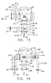
- a preferred embodiment comprises a ferrule or connector having an internal bore, preferably stepped, which is substantially parallel with the lengthwise axis of the ferrule body.
- the aforesaid bore allows for placement and bonding or potting of an optical fiber within and through said ferrule body.
- said ferrule body is also stepped in a unique form in order to optimally function as described herein.
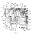
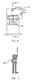
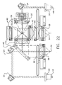
- the coaxial illuminated laser endoscopic probe and active numerical aperture control apparatus 10 also herein described as an illumination and laser source 10.
- the apparatus is especially suited for use during ophthalmic surgery.
- the present art utilizes a 75 watt xenon arc lamp 36 for its high luminance illumination (light density), greater than 6000 °K color temperature, and greater than 95 color rendering index.
- a unique and useful feature is the very high luminance and small size plasma ball formed on the end of the lamp 36 cathode. If imaged correctly the plasma ball is bright enough to provide the required illumination input to a small fiber such as that used for laser treatment.
- the xenon arc lamp 36 further provides an extremely small point light source which allows for a smaller output illumination beam 37 diameter.
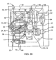
- Unique to the present lamp source is a mount 38 which allows for replacement of the lamp 36 and yet retains the location of the plasma ball of said source 36 precisely at a predetermined location within the optical center 35 of the apparatus.
- a classic spherical reflector 40 and two lens 42, 58 light collection layout is utilized rather than other lower part count layouts, such as using an elliptical reflector or a combination of a parabolic reflector and lens.
- This technique allows maximum collection efficiency with a minimum of geometric aberration.
- the lamp 36 is located at the geometrical center 35 of the reflector 40 and at the focus (focal point) of the first lens 42. Light that is incident on the reflector 40 is reflected back to the lamp 36. This forms an upside down or inverted image of the source 36 coincidental to the source 36.
- the first lens 42 collimates light from the source 36 and the upside down or inverted image.
- the second lens 58 is located coaxial to the first lens 42 and focuses the light at its focal point.
- the output optical fiber 60 is located at the focal point of the second lens 58.
- the aforesaid reflectors 40 are preferably spherical rather than parabolic in order to reflect illumination light in the same form as
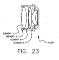
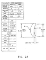
- Best form lenses 42, 58 (plano convex aspheric, facing each other) are used in the present art. It was discovered that chromatic aberrations, caused by the lenses, gave the output of the optical fiber 39, 60 either a yellow or blue cast. This is not a problem with other ophthalmic sources because the source is many times larger than the output optical fiber.
- a color corrected "f 1" or possibly .5 numerical aperture lens set 42, 58 consisting of four elements was designed to be utilized for each lens. Each of the elements is coated with a MgF (magnesium fluoride) anti-reflective coating to minimize light losses, with other anti-reflective coatings or layers also utilizable.
- MgF magnesium fluoride
- achromatic lens sets allows a high fidelity image of the illumination source 36 to be focused onto the end of the optical fiber 60, 64. That is, the multi-element lenses allow for a minimum of chromatic aberration.
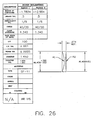
- the aforesaid four element lens set is shown and specifically described in the Figures.
- An additional separate illumination path 62 is possible with the present art.
- a 0.5 system numerical aperture or "f 1" lens is the greatest practical because of limitations to the numerical aperture of available optical fibers. This equates to 60 degrees full angle.
- f 1 numerical aperture
- the spherical reflector 40 is considered, an additional 60 degrees is provided from the total of 360 degrees available.
- Consideration of the vertical rotation around the source 36 is impractical because of shadows caused by the lamp 36 electrodes.
- a total of 240 degrees of horizontal rotation around the lamp 36 are left unaccounted for. Allowing for optics mounts 44 does account for some additional amount.
- at least half of the illumination output is available. This leaves room for a second light path 62 located orthogonal to the first path 11 along with the second fiber output 64.
- No other conventional illumination light source incorporates multiple light paths from a single lamp, that is two independent collection systems for illumination light. The independent nature of the two paths 11, 62 allow different filtering and intensity control settings to the two outputs 39, 41.
- Output dimming of the present art illumination system is accomplished by steering the first (collimating) or penultimate lens 42 in a fashion that does not change the lens 42 numerical aperture or introduce shadow artifacts into the beam 37.
- the lens set mount 44 has two halves 46 and a flat spring 52.
- the first part 48 is attached to the optics bench 12, the second part 50 holds the lens set 42, and the spring 52 connects the two 48, 50 together on one side.
- Pressure on the lens mount second part 50 causes the spring 52 to deflect and the lens 42 to move in a direction generally perpendicular to the optical axis. This results in motion or movement of the image across the face of the optical fiber 60, 64 whereby the peak illumination of the beam 37 is not centered on the optical fiber 60, 64 face during dimming.
- a shaft mounted cam 54 applies the pressure to the lens mount second part 50 and spring 52.
- a control knob 56 is attached to the other end of the shaft 53 and allows the user to select the desired illumination level by rotating the knob 56. This method is capable of providing at least 95% reduction in output illumination intensity.
- a shutter 57 is mounted upon the shaft 53 and is rotated across the illumination beam 37 in order to fully attenuate the output illumination intensity upon full rotation of said knob 56.
- Alternative embodiments may utilize other methods, including but not limited to electric or electronic drives, to rotate said shaft 53 instead of said knob 56.
- a dichroic "hot" mirror filter 66 is placed in the collimated space 61 between the illumination lenses 42, 58. This provides both UV and IR filtering of the light. Brackets are attached to the hot mirror 66 mount to provide a means for additional user selectable filters. Positioning of the filters is critical because this is the only area where the light 11 is generally normal to the filter surface. Location of the filter 66 on the other sides of the lenses would cause the light to have many undesirable incidence angles (between 0 and 30 degrees). Variation in the incidence angle causes dichroic reflectors or filters to have a shift in their affect. If absorption filters are used, placement outside the collimated space 61 will cause an increase in reflective losses and heating problems.
- the output optical fiber connector 98 is uniquely configured to provide the precise positioning required while reducing cost.
- a precise connector or mating end 116 is combined with an integral retention thread 130 to reduce parts cost and assembly time.
- An optional groove or recess 148 is placed on a second version of the connector to provide for sensing the difference between illumination only and laser compatible output fibers. Placement of a smooth diameter connector 74 into the output activates a switch 72 which will allow the laser power to be mixed. Either the lack of a connector 98 or the groove or recess 148 under the switch 72 will cause the switch 72 to not activate and the laser power will not be mixed in.
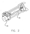
- laser light 14 is delivered to the system via a preferably 50 ⁇ m optical fiber 16 or equivalent.
- the connector 18 on the laser end is configured to be compatible with the laser and to provide the necessary interface to signal to the laser that a fiber is connected.
- the laser and light source 10 end preferably uses an SMA 905 connector or equivalent to allow repeatable connections of the laser delivery fiber 16.
- Laser light 14 exiting the delivery fiber is preferably collimated using a 16 mm focal length achromatic lens or equivalent 20, i.e. laser collimating lens, which can also be utilized to focus the collimated laser beam 22.
- the position of the fiber 16 is adjusted to be at the focal point of the lens 20.
- the input laser connector 18 and collimating lens 20 are located so that the collimated beam 22 is orthogonal to and intersects the center of the illumination axis 11 between the illumination lens sets 42, 58 (the collimated area for illumination light). If all safety requirements are met (i.e. laser output compatible fiber inserted and selection switch for laser output activated) a steering mirror 24 reflects the collimated laser light 22 into the center of the illumination axis 11.
- the steering mirror 24 is a first surface plano that is positioned at 45 degrees to the laser light 14 and is located in the center of the illumination axis 11 (when laser mode is active).
- a unique aspect of the present invention is that the thickness of the mirror 24 is shaped to appear as a circle when viewed along the illumination axis.
- the shaping causes the mirror 24 surface to appear elliptical when viewed from a normal angle.
- the size of the mirror 24 is chosen to be minimally larger that the collimated laser beam 22. Placement of the steering mirror 24 in the center of the illumination axis 11 causes the light rays that would normally be there to be blocked and a shadow to appear in the center of the output light cone.
- the second illumination lens 58 focuses the laser light 14 reflected by the steering mirror 24 onto the end of the output fiber 60, 64. Because the length of the output optical fiber strand is relatively short, the incidence angle of light entering the input end is very nearly the same angle on the output end.
- the laser provides an aiming beam, typically red, when not fully activated for treatment and a treatment beam, typically green, when fully activated. Without the shadow caused by the steering mirror 24 the aiming beam would be entirely washed out or imperceptible except at very low illumination levels.
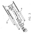
- Alternate embodiments may utilize more than one steering mirror 24 or place the steering mirror 24 outside of the illumination axis or illumination light path 11 and direct the laser light 14 through an aperture 158 in said spherical reflector 40 and thereafter through the arc lamp 36 plasma ball or through a dichroic reflector 160 or a reflector having an aperture 162. All of the aforesaid alternate embodiments place the laser light 14 within the collimated space 61 and utilize the second lens 58 for focus upon the output optical fiber 60. Moreover, all of the aforesaid alternate embodiments provide for a second light path 62 output as seen in the Figures.
- the laser steering mirror 24 is mechanically mounted on a thin post 28 that holds it in place while minimizing the loss of illumination light 11.
- the post 28 is mechanically connected to a bracket 30 which is connected to a solenoid 32.
- the solenoid 32 causes the bracket 30 and also the steering mirror 24 to move into one of two positions. Position one is outside the collimated illumination and laser light. This position is used for no laser delivery and allows the illumination path to operate unaffected. Position two is with the steering mirror 24 located to reflect the laser light into the illumination path 11. Motion of the solenoid 32 and bracket 30 are controlled by a precision ball slide 34. Use of the slide 34 insures repeatable positioning of the mirror 24.
- a coaxial laser and illumination path apparatus 10 which heretofore has not be available or utilized.
- a highly efficient illumination system utilizes spherical reflectors 40 and associated lenses 42, 58 to capture a maximum light output and also provide a twin path illumination light output from a single lamp source in order to feed fibers of diameter less than 500 ⁇ m.
- a laser or steering mirror 24 has a solenoid 32 selectability which provides an aiming hole within the illumination path 11 for laser placement.
- An illumination arc lamp 36 system has an extremely small point light source 36 which allows for an extremely small illumination focus size or numerical aperture output.
- An arc lamp 36 mount 38 precisely and interchangeably places the plasma ball of the arc lamp 36 at the focus or optical center 35 of the optics system.
- a unique dimming mechanism moves the focal point of an output dimming or first lens 42 in order to provide dimming without introducing artifacts, chromatic aberrations, or change of color temperature. Also there is a capability of connection with existing conventional laser light sources whereby laser treatment and illumination are both provided at an output of the present art apparatus 10.
- the optical system of the present apparatus 10 is capable of accepting the input cone angles of the illumination 33 and laser light 15 placed at the output optical fiber 60 and substantially reproducing said cone angles at the output of the optical fiber, typically where the endoscopic probe is located, with any aberrations caused by the optical fiber itself.
- FIG. 10 may utilize parabolic reflectors instead of spherical reflectors in order to collimate the illumination source 36. This technique would eliminate the need for the first collimating lens 42 and allow transmission of the laser beam 22 through an aperture within the parabolic reflector or via a steering mirror 24 within the collimated space 61. Still further alternate embodiments may utilize an elliptical reflector having two focal points whereby the illumination source 36 is placed at the first focal point and the output fiber 60 is placed at the second focal point with the laser beam 22 introduced through an aperture within the elliptical reflector or via a steering mirror 24 between the illumination source 36 and the output fiber 60. This latter alternate embodiment requires focusing the laser beam 22 onto the output fiber 60 via a lens placed within the laser beam path 22 prior to the output fiber 60 yet allows elimination of both the first collimating lens 42 and the second focusing lens 58.
- Some of the variables which determine the phototoxicity risk level during vitreoretinal surgery include the spectral and power characteristics of the light source used, the type and size of the endoilluminator probe, the length or duration of the surgical procedure, and the area (size) of the illuminated tissues. In each case the surgeon must make a risk-benefit judgement about the intensity of light to be used. Use of insufficient intensity may result in inadequate visualization and adverse effects more serious than a retinal photic injury.
- the calculation of the exposure time required to reach a point of injury is a tedious chore involving the numerical integration of the spectral power density function of the light source 36 with a hazard function (see ISO 15752), and specific knowledge of the surgical illumination area and endoilluminator characteristics.
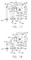
- an inexpensive photoxicity risk card 76 is removably attached to the control panel of the surgical illumination and laser light source 10.
- the card 76 is attached in close proximity to the light intensity control knob 56 in order to show the relationship between the output intensity of the light source and the likelihood of photic injury.
- the card 76 is preferably included with each endoilluminator instrument, i.e. optical fiber, that is calibrated to represent the phototoxic performance of that instrument type when used with a particular type of light source.
- the graphical representation 78 on the card 76 acts as a guide for adjustment of the output intensity of the source 10 in relationship to an accepted standard, that is such as the "Millennium” from Bausch and Lomb®. In this way the spectral and power characteristics of the various elements involved in delivering light to the eye are integrated into a single and easily manageable variable. This greatly reduces the complexity of judging the best intensity to use in a given situation.
- Alternative embodiment graphical representations 78 could present other information regarding the light output such as lumen output (a unit that is weighted by the photopic response of the eye). Other representations could present threshold information when used with special dyes or colored light filters.
- a preferred embodiment of the invention comprises a card 76 that is die-cut from white chipboard stock that is approximately the weight of a business card.
- the shape of the card 76 is generally square with a slot 90 removed from one side to enable the card 76 to be placed behind the intensity control knob 56 of the illumination and laser source 10 while providing clearance for the control shaft 53 which is turned by said knob 56.
- four location pins 92 are attached to the front panel of the illumination and laser source 10 enclosure. The pins 92 provide boundaries for card 76 location and tend to inhibit rotation of the card 76 with the control knob.
- a circular shaped scale 84 that has different color bands 86 representing the phototoxicity risk at a given intensity level, for example green, yellow, and red.
- the control knob 56 has an indication line that points to the current output intensity level and concurrent phototoxicity risk associated with the probe being used.
- Unique to the present art is the ability of the card 76 to indicate output intensity at the optical fiber output.
- the card 76 is meant to be disposed of after a single use and replaced with a new one provided with each optical fiber instrument. In this manner the output of the light source 10 is recalibrated each time it is used.
- the calibrated unit type may vary with different instrument styles to provide the surgeon with the most pertinent information possible.
- the card 76 provides a known point of reference relative to the prior art illumination devices. For example, if the surgeon maintains the knob 56 indicator line within the green color band, he or she will understand that the light intensity output is within the safe intensity of the prior art illuminators such as the "Millennium" from Bausch and Lomb®. This control phenomena is especially useful when utilizing more powerful illumination sources 10 such as described herein. That is, the surgeon must have a prior art point of reference when utilizing more powerful and modem illumination systems such as the present art.
- the art of the present invention may further provide several bands which do not provide a reference to the prior art but instead indicate phototoxicity levels or light intensity levels directly to the surgeon.
- the manufacturer of the optical fiber can provide a phototoxicity risk card 76 which accounts for attenuation and spectral absorption within the optical fiber provided with said card 76.
- the card may indicate that the surgeon must turn the intensity control knob 56 to a higher level in order to obtain an equivalency to one or more of the aforesaid prior art illuminators or to achieve a desired photo-illumination output.
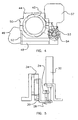
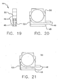
- a ferrule or connector 98 has an internal bore 102, preferably stepped 104, which is substantially parallel with the lengthwise axis 100 of the ferrule body 98.
- the aforesaid bore 102 allows for placement and bonding or potting of an optical fiber within and through said ferrule body 98.
- said ferrule body 98 is also stepped 112, 148 in a unique form in order to optimally function as described herein.
- the ferrule body 98 has an external end 114 and a mating end 116 and externally comprises a substantially cylindrical head 118 of a first diameter 120 having a first end 122 and a second end 123, said first end 122 co-located with said external end 114.
- Said ferrule body 98 further externally comprises a lip 124 of greater diameter than said head 118 and having a first side 126 and a second side 128 with said first side 126 mounted with said second end 123 of said head 118.
- a threaded portion 130 of preferably smaller diameter than said head 118 is attached with and extends from said lip 124 second side 128.
- said threaded portion 130 first comprises an 8-32 UNC thread with a first end 132 and second end 134, said first end 132 connected with said second side 128 of said lip 124. Also in a preferred embodiment, said threaded portion 130 has a groove 136 of approximately 0.76 mm (.030 inch) at said first end 132 with approximately 2.29 mm (.090 inch) of said thread 130 thereafter following and another approximately 0.76 mm (.030 inch) groove 136 following said thread 130 at said second end 134. Externally the ferrule body 98 also has an alignment barrel 138 having a first 140 and second 142 end following said threaded portion 130, said first end 140 attached with said threaded portion 130.
- the second end 142 of said alignment barrel 138 is co-located with said mating end 116 of said ferrule body 98.
- said second end 142 of said alignment barrel 138 contains an orifice 144 of substantially equivalent or slightly greater diameter as the optical fiber mounted within said stepped bore 102. Said orifice 144 is interconnected with said internal stepped bore 102 .
- said orifice is approximately 0.279 mm (.011 inch) in diameter and 0.635 mm (.025 inch) in length.
- said alignment barrel 138 has a chamfer 146 a the circumference of said second end 142.
- said chamfer 146 is of approximately 45 degree angle and 0.381 mm (.015 inch) in length.
- Alternative embodiments may utilize chamfers of different angles or shapes or forego use of a chamfer altogether.
- the alignment barrel 138 is uniquely shaped within the embodiments to indicate whether laser light or illumination light should be applied to the optical fiber.
- the alignment barrel is of uniform diameter, approximately .118 diameter, which indicates to the source 36 that laser light or energy is desired.
- the alignment barrel contains a recess 148 located approximately 1.905 m (.075 inch) from said barrel 138 second end 142 and extending approximately 6.807 mm (.268 inch) from said second end 142. When utilized, the illumination and laser source 10 detects this recess and determines that illumination light and not laser light is desired. Further alternative embodiments may utilize the aforesaid recess 148 embodiment for laser light and the uniform barrel diameter for illumination light.
- said stepped bore 102 first comprises a first larger bore substantially within said head portion which is of approximately 24.9 mm (.098 inch) diameter and extends substantially the length of said head.
- a second intermediate bore of approximately 1,6 mm (.063 inch) diameter extends from said first larger bore to said orifice 144 within said threaded portion 130 and said alignment barrel 138.
- the orifice 144 length is approximately 0.635 mm (.025 inch).
- Alternative embodiments may utilize first and second bores and orifices having a plurality of diameter and length sizes provided that the diameter portions are smaller than the ferrule external portions within which each is located.
- the optical fiber When assembled with an optical fiber, the optical fiber extends through said bore 102 and orifice 144 and terminates substantially flush with said ferrule body 98 mating end 116 or second end 142 of said alignment barrel 138.
- said optical fiber is held within said bore 102 via potting or adhesive compounds surrounding said fiber and attaching with said bore 102 of the ferrule 98.
- the external head 118 diameter is approximately 5.9 mm (.234 inch) with a length of approximately 9.5 mm (.375 inch.)
- the lip 124 external diameter is approximately .312 inch with a thickness of approximately 0.635 mm (.025 inch).
- said alignment barrel 138 is approximately 3 mm (.118 inch) in diameter and 9.65 mm (.380 inch) in length.
- the ferrule connector may be manufactured from a plurality of materials, including but not limited to metals, plastics, ceramics, or composites.
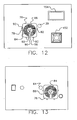
- a laser power meter 150 has a sensor 152, a power display 154, and associated control circuitry 156.
- the power meter 150 allows a surgeon to place the endoscopic fiber optic probe onto said sensor 152, energize the laser through the illumination and laser source 10 and measure the laser power output as seen on said display 154. Inclusion of the aforesaid is especially useful due to variations in optical fibers or to account for attenuation through the illumination and laser source 10.
- the surgeon has complete knowledge of the laser power transmitted to the surgical site.
- Alternative embodiments may utilize said power meter 150 for measurement of the output illumination 37 intensity as well as the laser light 14 power.
- the surgeon connects a laser light source via optical fiber to the input laser connector 18 on the apparatus 10.
- the surgeon thereafter connects a ferrule connector 98 with an integral optical fiber connected with an endoscopic probe at the first output 39 or for illumination only at said second output 64. If said ferrule connector 98 at said first output 39 does not have the aforedescribed recess 148, the apparatus 10 will allow the steering mirror 24 to position within the illumination light path 11 and further allow transmission of laser light.
- the surgeon desires to measure laser power output, he or she places the output end of the endoscopic probe onto said sensor 152 and upon full laser activation, reads the laser power output on the display 154.
- the surgeon proceeds to illuminate the tissues of concern with a cone of white illumination light having a shadow where the laser beam will be placed and a typically red laser aiming beam within said shadow.
- a typically green treatment laser beam replaces said typically red aiming beam to treat the tissues of concern. All of the aforesaid illumination and treatment may be achieved with a single incision and through a single optical fiber of smaller diameter than prior art sources.
- a coaxial illuminated laser endoscopic probe and active numerical aperture control apparatus 10 (illumination and laser source) and method of use such has been shown and described.
- the apparatus and method of use allows for simultaneous transmission of illumination and laser treatment light through a single optical fiber of a size which is typically utilized for laser treatment light only.
- the apparatus and method further provides control of the angular light output from the endoscopic probe attached with said optical fiber.
- the apparatus also provides for distinct and separate illumination without utilization of the treatment laser while providing complete intensity control of said illumination.
- a medical light intensity phototoxicity control or risk card 76 has also been shown and described for use.
- Said phototoxicity risk card 76 is especially useful for quick and easy determination of illumination intensity output from a specific type of optical fiber or higher power source.
- a photon illumination and laser ferrule connector 98 has also been shown and described.
- Said ferrule 98 is especially useful for quick and positive connection of an optical fiber to a laser or illumination source 10 as herein described and further allows said source 10 to distinguish the optical fiber type or use, that is for illumination or medical laser application.
- the present art device is useful during surgery and especially ophthalmic surgery. Also, those skilled in the art will appreciate the integral inclusion of a laser optical fiber output power meter.
Landscapes
- Health & Medical Sciences (AREA)
- Physics & Mathematics (AREA)
- Life Sciences & Earth Sciences (AREA)
- Surgery (AREA)
- Optics & Photonics (AREA)
- Nuclear Medicine, Radiotherapy & Molecular Imaging (AREA)
- Veterinary Medicine (AREA)
- General Health & Medical Sciences (AREA)
- Engineering & Computer Science (AREA)
- Biomedical Technology (AREA)
- Heart & Thoracic Surgery (AREA)
- Public Health (AREA)
- Animal Behavior & Ethology (AREA)
- Ophthalmology & Optometry (AREA)
- Molecular Biology (AREA)
- Medical Informatics (AREA)
- Otolaryngology (AREA)
- Electromagnetism (AREA)
- Vascular Medicine (AREA)
- General Physics & Mathematics (AREA)
- Biophysics (AREA)
- Pathology (AREA)
- Radiology & Medical Imaging (AREA)
- Laser Surgery Devices (AREA)
- Non-Portable Lighting Devices Or Systems Thereof (AREA)
- Endoscopes (AREA)
Claims (13)
- Source d'éclairage et de laser comprenant :une source d'éclairage (36) ayant une sortie de lumière d'éclairage (11),une source de lumière laser ayant une sortie de lumière laser (14), etun moyen pour mélanger ladite lumière d'éclairage (11) et ladite lumière laser (14) et focaliser ladite lumière d'éclairage (11) et ladite lumière laser (14) sur une unique fibre optique de sortie (60), dans laquelle ladite lumière laser (14) et ladite lumière d'éclairage (11) sont transmises par l'intermédiaire de ladite unique fibre optique de sortie (60),caractérisée par- la source d'éclairage (36) ayant une sortie de lumière d'éclairage (11) à large spectre visible chirurgicalement utile- un miroir de pilotage (24) agencé dans un centre de la lumière d'éclairage (11) pour réfléchir la lumière laser (14) dans le centre de la lumière d'éclairage (11), causant ainsi une apparition d'ombre dans un cône de sortie de la lumière d'éclairage (11) à la sortie de la fibre optique de sortie (60), et- un moyen pour atténuer ladite lumière d'éclairage (11) ayant une commande sans affecter sensiblement les caractéristiques spectrales de ladite lumière d'éclairage.
- Source d'éclairage et de laser selon la revendication 1 dans laquelle ledit moyen pour mélanger ladite lumière d'éclairage et ladite lumière laser comprend en outre : un moyen pour sensiblement préserver un cône de lumière d'éclairage ayant un premier angle de cône (33) de ladite sortie de lumière d'éclairage et un cône de lumière laser ayant un deuxième angle de cône (15) de ladite sortie de lumière laser à une sortie de ladite fibre optique de sortie (60).
- Source d'éclairage et de laser selon la revendication 2 dans laquelle ledit cône de lumière d'éclairage a une ombre à l'intérieur de laquelle est située ladite lumière laser (14) à ladite sortie de ladite fibre optique (60), dans laquelle un ou plusieurs tissu(s) d'intérêt peuvent être éclairés et ladite ombre apparaît sur lesdits tissus là où ladite lumière laser (14) délivre un traitement.
- Source d'éclairage et de laser selon la revendication 1 dans laquelle ledit moyen pour mélanger ladite lumière d'éclairage (11) et ladite lumière laser (14) comprend :un moyen pour collimater ladite lumière laser (14) en un faisceau collimaté (22) de lumière laser, etun moyen pour collimater ladite lumière d'éclairage (11) en un faisceau collimaté de lumière d'éclairage, etun moyen pour combiner lesdits faisceaux collimatés ensemble, etun moyen pour focaliser lesdits faisceaux collimatés sur ladite unique fibre optique de sortie (60), etladite sortie de ladite fibre optique (60) apte à éclairer un ou plusieurs tissu(s) avec ladite lumière d'éclairage (11) et sélectivement apte à traiter un ou plusieurs tissu(s) avec ladite lumière laser (14).
- Source d'éclairage et de laser selon la revendication 1 comprenant en outre :un moyen de connecteur pour connecter ladite fibre optique de sortie (60), ledit moyen de connecteur fournissant une indication si ladite fibre optique de sortie (60) est conçue, la plus appropriée, ou désirée pour ladite lumière d'éclairage (11) ou ladite lumière laser (14) ou les deux de ladite lumière d'éclairage (11) et de ladite lumière laser (14).
- Source d'éclairage et de laser selon la revendication 1 comprenant en outre une carte de risque de phototoxicité (76) pouvant être placée à proximité de ou sur ladite commande et apte à indiquer une intensité de sortie sûre ou connue de ladite lumière d'éclairage (11).
- Source d'éclairage et de laser selon la revendication 4 dans laquelle :ledit moyen pour collimater ladite lumière laser (14) en un faisceau collimaté (22) de lumière laser comprend une lentille de collimation de laser (20), etledit moyen pour collimater ladite lumière d'éclairage (11) en un faisceau collimaté de lumière d'éclairage comprend une première lentille de collimation (42), etledit moyen pour combiner lesdits faisceaux collimatés ensemble comprend un miroir de pilotage (24) qui réfléchit ladite lumière laser collimatée (22) de ladite lentille de collimation de laser (20) en un axe d'éclairage (11) de ladite lumière d'éclairage collimatée, etledit moyen pour focaliser lesdits faisceaux collimatés sur ladite fibre optique de sortie (60) comprend une deuxième lentille de focalisation (58).
- Source d'éclairage et de laser selon la revendication 7 dans laquelle ledit moyen pour combiner lesdits faisceaux collimatés ensemble comprend ledit miroir de pilotage (24) positionné à 45 degrés par rapport à ladite lumière laser collimatée (22) et dans un centre dudit axe d'éclairage (11) et formé de façon à apparaître comme un cercle lorsqu'il est vu sur ledit axe d'éclairage (11) et qui positionne ladite lumière laser collimatée (22) avec ladite lumière d'éclairage collimatée.
- Source d'éclairage et de laser selon la revendication 1 comprenant en outre :un deuxième chemin de lumière d'éclairage (62) orthogonal à ladite lumière d'éclairage (11), etun moyen pour focaliser ledit deuxième chemin de lumière d'éclairage (62) sur une deuxième fibre optique de sortie (64), dans laquelle ladite lumière laser (14) est omise de ladite lumière d'éclairage (11) dans ledit deuxième chemin de lumière d'éclairage (62) et dans laquelle ladite lumière laser (14) et ladite lumière d'éclairage (11) transmises par l'intermédiaire de ladite fibre optique de sortie (64) sensiblement unique sont non affectées par ledit deuxième chemin de lumière d'éclairage (62).
- Source d'éclairage et de laser selon la revendication 1 dans laquelle ledit moyen pour atténuer ladite lumière d'éclairage (11) comprend une lentille pilotable (42) apte à déplacer ladite image de ladite source d'éclairage (36) au travers de ladite face de ladite fibre optique de sortie (60).
- Source d'éclairage et de laser selon la revendication 4 comprenant en outre un ou plusieurs filtre(s) (66) de lumière d'éclairage placé(s) à l'intérieur de ladite lumière d'éclairage collimatée.
- Source d'éclairage et de laser selon la revendication 11 dans laquelle lesdits filtres (66) sont placés à l'intérieur de ladite lumière d'éclairage collimatée de manière sensiblement normale à ladite lumière d'éclairage (11).
- Source d'éclairage selon la revendication 1 dans laquelle ladite source d'éclairage comprend une lampe à arc (36) ayant une monture (38) qui permet le remplacement de ladite lampe à arc (36) et cependant maintient un emplacement d'une bille de plasma de ladite source d'éclairage précisément en un emplacement prédéterminé au sein d'un centre optique (35).
Priority Applications (5)
| Application Number | Priority Date | Filing Date | Title |
|---|---|---|---|
| EP10180552.1A EP2298212B1 (fr) | 2003-07-28 | 2004-07-27 | Éclairage et source laser |
| EP10180567.9A EP2293127B1 (fr) | 2003-07-28 | 2004-07-27 | Connecteur d'embout pour une utilisation avec un éclairage ou une source laser |
| EP10180556.2A EP2298213B1 (fr) | 2003-07-28 | 2004-07-27 | Source d'illumination |
| EP10180562.0A EP2298214B1 (fr) | 2003-07-28 | 2004-07-27 | Éclairage et source laser et procédé pour la transmission de la lumière d'éclairage et de la lumière de traitement laser |
| EP10180579.4A EP2292174B1 (fr) | 2003-07-28 | 2004-07-27 | Source d'illumination |
Applications Claiming Priority (6)
| Application Number | Priority Date | Filing Date | Title |
|---|---|---|---|
| US49039903P | 2003-07-28 | 2003-07-28 | |
| US55097904P | 2004-03-05 | 2004-03-05 | |
| US57774004P | 2004-06-05 | 2004-06-05 | |
| US57761804P | 2004-06-05 | 2004-06-05 | |
| US10/900,939 US7189226B2 (en) | 2003-07-28 | 2004-07-27 | Coaxial illuminated laser endoscopic probe and active numerical aperture control |
| PCT/US2004/024116 WO2005016118A2 (fr) | 2003-07-28 | 2004-07-27 | Sonde endoscopique laser a eclairage coaxial et commande d'ouverture numerique active |
Related Child Applications (8)
| Application Number | Title | Priority Date | Filing Date |
|---|---|---|---|
| EP10180567.9A Division EP2293127B1 (fr) | 2003-07-28 | 2004-07-27 | Connecteur d'embout pour une utilisation avec un éclairage ou une source laser |
| EP10180556.2A Division EP2298213B1 (fr) | 2003-07-28 | 2004-07-27 | Source d'illumination |
| EP10180552.1A Division EP2298212B1 (fr) | 2003-07-28 | 2004-07-27 | Éclairage et source laser |
| EP10180562.0 Division-Into | 2010-09-28 | ||
| EP10180567.9 Division-Into | 2010-09-28 | ||
| EP10180579.4 Division-Into | 2010-09-28 | ||
| EP10180556.2 Division-Into | 2010-09-28 | ||
| EP10180552.1 Division-Into | 2010-09-28 |
Publications (3)
| Publication Number | Publication Date |
|---|---|
| EP1653896A2 EP1653896A2 (fr) | 2006-05-10 |
| EP1653896A4 EP1653896A4 (fr) | 2008-03-19 |
| EP1653896B1 true EP1653896B1 (fr) | 2013-04-03 |
Family
ID=34199332
Family Applications (1)
| Application Number | Title | Priority Date | Filing Date |
|---|---|---|---|
| EP04786120A Not-in-force EP1653896B1 (fr) | 2003-07-28 | 2004-07-27 | Sonde endoscopique laser a eclairage coaxial |
Country Status (6)
| Country | Link |
|---|---|
| US (2) | US7189226B2 (fr) |
| EP (1) | EP1653896B1 (fr) |
| JP (3) | JP2007500546A (fr) |
| ES (6) | ES2404065T3 (fr) |
| PT (5) | PT1653896E (fr) |
| WO (1) | WO2005016118A2 (fr) |
Families Citing this family (56)
| Publication number | Priority date | Publication date | Assignee | Title |
|---|---|---|---|---|
| JP2006016438A (ja) * | 2004-06-30 | 2006-01-19 | Dongwoo Fine-Chem Co Ltd | 電子部品洗浄液 |
| WO2007053590A1 (fr) * | 2005-10-31 | 2007-05-10 | Alcon, Inc. | Illuminateur telescopique de petit gabarit |
| US8126302B2 (en) | 2006-03-31 | 2012-02-28 | Novartis Ag | Method and system for correcting an optical beam |
| NL1032559C2 (nl) * | 2006-09-22 | 2008-03-26 | D O R C Dutch Ophthalmic Res C | Oogchirurgische verlichtingseenheid, lichtgeleider, werkwijze, computerprogramma product en computersysteem. |
| WO2008057877A2 (fr) * | 2006-11-03 | 2008-05-15 | Iridex Corporation | Appareil de traitement à sonde laser d'éclairage à pointe mise en forme |
| US20080183160A1 (en) * | 2007-01-26 | 2008-07-31 | Michael Papac | Ignition limited illuminator |
| JP2010520801A (ja) * | 2007-03-13 | 2010-06-17 | オプティメディカ・コーポレイション | 眼球手術及び減張切開部を作成するための装置 |
| US20080246919A1 (en) * | 2007-04-09 | 2008-10-09 | Ron Smith | Ophthalmic Endoilluminator with Hybrid Lens |
| NL1034206C2 (nl) * | 2007-07-30 | 2009-02-02 | D O R C Dutch Ophthalmic Res C | Oogchirurgische eenheid en oogchirurgisch instrument. |
| US7682089B2 (en) * | 2007-08-15 | 2010-03-23 | Rohlen Brooks H | System and method for positioning a probe |
| US8647333B2 (en) * | 2007-11-03 | 2014-02-11 | Cygnus Llc | Ophthalmic surgical device |
| US7969866B2 (en) * | 2008-03-31 | 2011-06-28 | Telefonaktiebolaget L M Ericsson (Publ) | Hierarchical virtual private LAN service hub connectivity failure recovery |
| US10368838B2 (en) | 2008-03-31 | 2019-08-06 | Intuitive Surgical Operations, Inc. | Surgical tools for laser marking and laser cutting |
| US7708409B1 (en) | 2008-12-11 | 2010-05-04 | Bausch & Lomb Incorporated | Controlling beam intensity in ophthalmic illumination systems using serial rotatable shapes |
| US20100318074A1 (en) * | 2009-06-10 | 2010-12-16 | Bruno Dacquay | Ophthalmic endoillumination using low-power laser light |
| DE102009040093A1 (de) | 2009-09-04 | 2011-04-07 | Olympus Winter & Ibe Gmbh | Medizinische Leuchte für Hintergrundlicht und Anregungslicht |
| US10226167B2 (en) | 2010-05-13 | 2019-03-12 | Beaver-Visitec International, Inc. | Laser video endoscope |
| US20160095507A1 (en) | 2010-05-13 | 2016-04-07 | Beaver-Visitec International, Inc. | Laser video endoscope |
| WO2012014145A1 (fr) * | 2010-07-26 | 2012-02-02 | Lumenis Ltd. | Estimation de distance entre une extrémité de fibre et un tissu utilisant une modulation d'ouverture numérique |
| CA2835848A1 (fr) | 2011-05-12 | 2012-11-15 | Olive Medical Corporation | Capteur d'images comportant des interconnexions d'optimisation de tolerance |
| US8688401B2 (en) | 2011-12-22 | 2014-04-01 | Alcon Research, Ltd. | Providing consistent output from an endoilluminator system |
| US9335455B2 (en) | 2012-05-30 | 2016-05-10 | Cygnus, LP | Extended tip laser and illumination probe for retina surgery |
| CA2913788C (fr) | 2012-05-30 | 2020-09-15 | Ellex R&D Pty Ltd | Eclairage coaxial reflex |
| IN2015MN00020A (fr) | 2012-07-26 | 2015-10-16 | Olive Medical Corp | |
| CA2878514A1 (fr) | 2012-07-26 | 2014-01-30 | Olive Medical Corporation | Systeme d'eclairage pulse ycbcr dans un environnement insuffisamment eclaire |
| IN2015MN00018A (fr) | 2012-07-26 | 2015-10-16 | Olive Medical Corp | |
| KR102143807B1 (ko) | 2012-07-26 | 2020-08-31 | 디퍼이 신테스 프로덕츠, 인코포레이티드 | 최소 영역 모노리식 cmos 이미지 센서를 가진 카메라 시스템 |
| US10245181B2 (en) * | 2012-12-21 | 2019-04-02 | Alcon Research, Ltd. | Grin fiber multi-spot laser probe |
| WO2014134501A2 (fr) | 2013-02-28 | 2014-09-04 | Olive Medical Corporation | Vidéostroboscopie des cordes vocales au moyen de capteurs cmos |
| CN105246395B (zh) | 2013-03-15 | 2019-01-22 | 德普伊新特斯产品公司 | 综合固定模式噪声消除 |
| US9777913B2 (en) | 2013-03-15 | 2017-10-03 | DePuy Synthes Products, Inc. | Controlling the integral light energy of a laser pulse |
| AU2014233190B2 (en) | 2013-03-15 | 2018-11-01 | DePuy Synthes Products, Inc. | Image sensor synchronization without input clock and data transmission clock |
| EP2967294B1 (fr) | 2013-03-15 | 2020-07-29 | DePuy Synthes Products, Inc. | Super-résolution et correction d'artéfacts de mouvements pour un système d'imagerie avec illumination à couleurs pulsées |
| WO2014144997A1 (fr) | 2013-03-15 | 2014-09-18 | Olive Medical Corporation | Système et méthode d'élimination du chatoiement d'une scène éclairée par une source de lumière cohérente |
| CA2906802A1 (fr) | 2013-03-15 | 2014-09-18 | Olive Medical Corporation | Amelioration de bord sensible au bruit |
| CN105283117B (zh) | 2013-03-15 | 2020-06-30 | 德普伊新特斯产品公司 | 使用远侧端帽进行校正 |
| BR112015022987A2 (pt) | 2013-03-15 | 2017-07-18 | Olive Medical Corp | visualização de trocarte com prisma integrado para uso com endoscópio angulado |
| AU2014233464B2 (en) | 2013-03-15 | 2018-11-01 | DePuy Synthes Products, Inc. | Scope sensing in a light controlled environment |
| AU2014233192B2 (en) | 2013-03-15 | 2018-11-22 | DePuy Synthes Products, Inc. | Minimize image sensor I/O and conductor counts in endoscope applications |
| US10362240B2 (en) | 2013-03-15 | 2019-07-23 | DePuy Synthes Products, Inc. | Image rotation using software for endoscopic applications |
| IL234727B (en) * | 2013-09-20 | 2020-09-30 | Asml Netherlands Bv | A light source operated by a laser in an optical system corrected for deviations and the method of manufacturing the system as mentioned |
| CA2936453A1 (fr) | 2014-01-09 | 2015-07-16 | Axiosonic, Llc | Systemes et methodes utilisant des ultrasons pour un traitement |
| EP3119265B1 (fr) | 2014-03-21 | 2019-09-11 | DePuy Synthes Products, Inc. | Connecteur latéral de carte pour un capteur d'imagerie |
| CA2952962C (fr) | 2014-06-19 | 2022-08-23 | Daniel SIPPLE | Systeme et appareil de detection et d'identification de biomarqueurs |
| ITUB20155218A1 (it) * | 2015-10-16 | 2017-04-16 | Alberto Micco | Sistema per guidare dispositivi medici |
| US9869854B2 (en) | 2015-12-16 | 2018-01-16 | Canon U.S.A, Inc. | Endoscopic system |
| KR101894866B1 (ko) * | 2016-10-13 | 2018-10-04 | 한국전기연구원 | 의료용 광원모듈 및 그를 가지는 의료용 광원장치 |
| US11213426B2 (en) | 2017-12-12 | 2022-01-04 | Alcon Inc. | Thermally robust multi-spot laser probe |
| US11135092B2 (en) | 2017-12-12 | 2021-10-05 | Alcon Inc. | Multi-core fiber for a multi-spot laser probe |
| US11291470B2 (en) | 2017-12-12 | 2022-04-05 | Alcon Inc. | Surgical probe with shape-memory material |
| EP3709942B1 (fr) | 2017-12-12 | 2023-09-13 | Alcon Inc. | Sonde laser multipoint éclairée couplée à entrées multiples |
| EP3874304A4 (fr) | 2018-11-01 | 2022-08-03 | Medical Instrument Development Laboratories, Inc. | Système d'éclairage à diodes électroluminescentes (del) |
| US11931297B2 (en) | 2019-06-14 | 2024-03-19 | Alcon Inc. | Glare reduction endoilluminators |
| CN114650764A (zh) * | 2019-11-13 | 2022-06-21 | 索尼奥林巴斯医疗解决方案公司 | 光源设备与被检体观察系统 |
| EP4070142A1 (fr) | 2019-12-04 | 2022-10-12 | Alcon Inc. | Fibre optique à âmes multiples (mcf) à formation de bulles réduite |
| US11493692B2 (en) | 2020-02-18 | 2022-11-08 | Alcon Inc. | Multi-spot laser probe with multiple single-core fibers |
Family Cites Families (38)
| Publication number | Priority date | Publication date | Assignee | Title |
|---|---|---|---|---|
| US2131852A (en) * | 1936-07-27 | 1938-10-04 | Research Corp | Light projecting system |
| US4027938A (en) * | 1976-07-01 | 1977-06-07 | The United States Of America As Represented By The Secretary Of The Navy | Fiber optic cable connector |
| US4127319A (en) * | 1977-06-01 | 1978-11-28 | Amp Incorporated | Termination means for fiber optic bundle |
| US4447121A (en) * | 1981-11-06 | 1984-05-08 | Amp Incorporated | Connector for fiber optic member |
| JPS58105202A (ja) * | 1981-12-18 | 1983-06-23 | Olympus Optical Co Ltd | 光学繊維束を用いた照明装置 |
| US4529230A (en) * | 1982-02-26 | 1985-07-16 | Supelco, Inc. | Capillary tubing and small rod connector |
| JPS6264334A (ja) * | 1985-09-12 | 1987-03-23 | キヤノン株式会社 | 眼科用照明装置 |
| JPH0434818Y2 (fr) * | 1986-06-12 | 1992-08-19 | ||
| US4757426A (en) | 1986-11-06 | 1988-07-12 | Storz Instrument Company | Illumination system for fiber optic lighting instruments |
| EP0292695B1 (fr) * | 1987-05-25 | 1993-02-17 | Deutsche Aerospace AG | Dispositif d'irradiation circonférentielle d'objets |
| JP2585646B2 (ja) * | 1987-11-27 | 1997-02-26 | 興和株式会社 | レーザー治療装置 |
| US4919508A (en) * | 1988-08-04 | 1990-04-24 | The Spectranetics Corporation | Fiberoptic coupler |
| JPH02154752A (ja) * | 1988-08-16 | 1990-06-14 | Olympus Optical Co Ltd | レーザ装置 |
| US5003189A (en) * | 1989-10-10 | 1991-03-26 | Unisys Corp. | Document-imaging illumination with fibre-optic intensity-adjust |
| JPH0775624B2 (ja) * | 1989-10-25 | 1995-08-16 | エイ.レスペランス フランシス | 血管増殖や他の組織増殖を強化するための装置 |
| JPH03199779A (ja) * | 1989-12-26 | 1991-08-30 | Komatsu Ltd | 高圧シール用バックアップリング |
| JPH04212342A (ja) * | 1990-02-21 | 1992-08-03 | Kazuo Ichikawa | 眼内照明装置 |
| ES2106127T3 (es) | 1991-05-06 | 1997-11-01 | Martin M D Uram | Endoscopio con video por laser. |
| US5121740A (en) * | 1991-05-06 | 1992-06-16 | Martin Uram | Laser video endoscope |
| JP3199779B2 (ja) * | 1991-06-29 | 2001-08-20 | 株式会社ニデック | 眼内光凝固装置 |
| US5275593A (en) * | 1992-04-30 | 1994-01-04 | Surgical Technologies, Inc. | Ophthalmic surgery probe assembly |
| US5419312A (en) * | 1993-04-20 | 1995-05-30 | Wildflower Communications, Inc. | Multi-function endoscope apparatus |
| US5396571A (en) * | 1993-05-21 | 1995-03-07 | Trimedyne, Inc. | Coupling device and method for improved transfer efficiency of light energy from a laser source into optical fibers |
| US5509095A (en) * | 1994-02-01 | 1996-04-16 | Cogent Light Technologies, Inc. | Condensing and collecting optical system with axially displaced concave reflector and optical fiber |
| US5921981A (en) * | 1995-11-09 | 1999-07-13 | Alcon Laboratories, Inc. | Multi-spot laser surgery |
| US5993072A (en) * | 1996-04-17 | 1999-11-30 | The Johns Hopkins University | Adapter assembly for connecting multiple optic fiber illuminated microsurgical instruments to a single light source |
| JP4059555B2 (ja) * | 1997-03-25 | 2008-03-12 | テルモ株式会社 | 医療用レーザ照射装置 |
| US6008889A (en) * | 1997-04-16 | 1999-12-28 | Zeng; Haishan | Spectrometer system for diagnosis of skin disease |
| AU9102798A (en) * | 1997-08-14 | 1999-03-08 | Mark G Fontenot | Multi-channel transmyocardial laser revascularization |
| US5997141A (en) * | 1998-03-06 | 1999-12-07 | Odyssey Optical Systems, Llc | System for treating the fundus of an eye |
| JP3866858B2 (ja) * | 1998-04-30 | 2007-01-10 | 株式会社ニデック | レーザ治療装置 |
| US6485414B1 (en) * | 1998-07-13 | 2002-11-26 | Ceramoptec Industries, Inc. | Color video diagnostic system for mini-endoscopes |
| US6229940B1 (en) * | 1998-11-30 | 2001-05-08 | Mcdonnell Douglas Corporation | Incoherent fiber optic laser system |
| US6606173B2 (en) * | 2000-08-01 | 2003-08-12 | Riake Corporation | Illumination device and method for laser projector |
| JP2002286920A (ja) * | 2000-09-22 | 2002-10-03 | Fuji Electric Co Ltd | 回折型光学素子 |
| US6519485B2 (en) * | 2000-12-13 | 2003-02-11 | The General Hospital Corporation | Minimally invasive system for assessment of organ function |
| DE10117347B4 (de) * | 2001-04-06 | 2006-04-13 | W&H Dentalwerk Bürmoos Gesellschaft m.b.H. | Laserbehandlungsgeräte mit Beleuchtungsystem |
| US6892013B2 (en) * | 2003-01-15 | 2005-05-10 | Negevtech Ltd. | Fiber optical illumination system |
-
2004
- 2004-07-27 PT PT47861208T patent/PT1653896E/pt unknown
- 2004-07-27 PT PT101805679T patent/PT2293127E/pt unknown
- 2004-07-27 ES ES04786120T patent/ES2404065T3/es active Active
- 2004-07-27 PT PT101805794T patent/PT2292174E/pt unknown
- 2004-07-27 ES ES10180556.2T patent/ES2632563T3/es active Active
- 2004-07-27 ES ES10180562T patent/ES2436199T3/es active Active
- 2004-07-27 US US10/900,939 patent/US7189226B2/en active Active - Reinstated
- 2004-07-27 ES ES10180552.1T patent/ES2523964T3/es active Active
- 2004-07-27 ES ES10180567.9T patent/ES2521691T3/es active Active
- 2004-07-27 WO PCT/US2004/024116 patent/WO2005016118A2/fr active Application Filing
- 2004-07-27 JP JP2006521988A patent/JP2007500546A/ja active Pending
- 2004-07-27 ES ES10180579T patent/ES2415509T3/es active Active
- 2004-07-27 PT PT101805620T patent/PT2298214E/pt unknown
- 2004-07-27 EP EP04786120A patent/EP1653896B1/fr not_active Not-in-force
- 2004-07-27 PT PT101805521T patent/PT2298212E/pt unknown
-
2007
- 2007-01-31 US US11/701,339 patent/US20070135806A1/en not_active Abandoned
-
2009
- 2009-07-17 JP JP2009169388A patent/JP5043897B2/ja not_active Expired - Fee Related
-
2011
- 2011-06-17 JP JP2011135423A patent/JP2011255188A/ja active Pending
Also Published As
| Publication number | Publication date |
|---|---|
| WO2005016118A3 (fr) | 2006-02-16 |
| EP1653896A4 (fr) | 2008-03-19 |
| US20050033389A1 (en) | 2005-02-10 |
| JP5043897B2 (ja) | 2012-10-10 |
| ES2436199T3 (es) | 2013-12-27 |
| PT2292174E (pt) | 2013-07-09 |
| JP2011255188A (ja) | 2011-12-22 |
| US7189226B2 (en) | 2007-03-13 |
| WO2005016118A2 (fr) | 2005-02-24 |
| PT2298214E (pt) | 2013-11-28 |
| ES2632563T3 (es) | 2017-09-14 |
| PT1653896E (pt) | 2013-05-07 |
| ES2404065T3 (es) | 2013-05-23 |
| ES2521691T3 (es) | 2014-11-13 |
| JP2009279420A (ja) | 2009-12-03 |
| PT2293127E (pt) | 2014-10-30 |
| ES2415509T3 (es) | 2013-07-25 |
| US20070135806A1 (en) | 2007-06-14 |
| ES2523964T3 (es) | 2014-12-03 |
| EP1653896A2 (fr) | 2006-05-10 |
| JP2007500546A (ja) | 2007-01-18 |
| PT2298212E (pt) | 2014-11-18 |
Similar Documents
| Publication | Publication Date | Title |
|---|---|---|
| EP1653896B1 (fr) | Sonde endoscopique laser a eclairage coaxial | |
| US20070139924A1 (en) | Coaxial illuminated laser endoscopic probe and active numerical aperture control | |
| AU2006308686B2 (en) | Surgical wide-angle illuminator | |
| US10433718B2 (en) | Eye safe laser illumination in ophthalmic surgeries | |
| JP2023138671A (ja) | 多重入力結合照光式マルチスポットレーザプローブ | |
| CA2773582C (fr) | Sonde d'eclairage structuree et procede associe | |
| JP2007510478A (ja) | レーザ治療器具をオブジェクトに接続するアダプター | |
| AU2008275551A1 (en) | Ophthalmic endoilluminator with hybrid lens | |
| JP2010063485A (ja) | 内視鏡用照明光学系及び内視鏡 |
Legal Events
| Date | Code | Title | Description |
|---|---|---|---|
| PUAI | Public reference made under article 153(3) epc to a published international application that has entered the european phase |
Free format text: ORIGINAL CODE: 0009012 |
|
| 17P | Request for examination filed |
Effective date: 20060214 |
|
| AK | Designated contracting states |
Kind code of ref document: A2 Designated state(s): AT BE BG CH CY CZ DE DK EE ES FI FR GB GR HU IE IT LI LU MC NL PL PT RO SE SI SK TR |
|
| AX | Request for extension of the european patent |
Extension state: AL HR LT LV MK |
|
| RAP1 | Party data changed (applicant data changed or rights of an application transferred) |
Owner name: SYNERGETICS, INC. |
|
| RIN1 | Information on inventor provided before grant (corrected) |
Inventor name: JAMES C. EASLEY Inventor name: GREGG SCHELLER Inventor name: MICHAEL D. AULD Inventor name: JONATHAN S. KANE |
|
| DAX | Request for extension of the european patent (deleted) | ||
| A4 | Supplementary search report drawn up and despatched |
Effective date: 20080214 |
|
| 17Q | First examination report despatched |
Effective date: 20080612 |
|
| RIN1 | Information on inventor provided before grant (corrected) |
Inventor name: JONATHAN S. KANE Inventor name: JAMES C. EASLEY Inventor name: MICHAEL D. AULD Inventor name: GREGG SCHELLER |
|
| GRAP | Despatch of communication of intention to grant a patent |
Free format text: ORIGINAL CODE: EPIDOSNIGR1 |
|
| GRAS | Grant fee paid |
Free format text: ORIGINAL CODE: EPIDOSNIGR3 |
|
| GRAP | Despatch of communication of intention to grant a patent |
Free format text: ORIGINAL CODE: EPIDOSNIGR1 |
|
| GRAA | (expected) grant |
Free format text: ORIGINAL CODE: 0009210 |
|
| AK | Designated contracting states |
Kind code of ref document: B1 Designated state(s): AT BE BG CH CY CZ DE DK EE ES FI FR GB GR HU IE IT LI LU MC NL PL PT RO SE SI SK TR |
|
| REG | Reference to a national code |
Ref country code: GB Ref legal event code: FG4D |
|
| REG | Reference to a national code |
Ref country code: CH Ref legal event code: EP Ref country code: AT Ref legal event code: REF Ref document number: 604236 Country of ref document: AT Kind code of ref document: T Effective date: 20130415 |
|
| REG | Reference to a national code |
Ref country code: CH Ref legal event code: NV Representative=s name: ING. MARCO ZARDI C/O M. ZARDI AND CO. S.A., CH |
|
| REG | Reference to a national code |
Ref country code: PT Ref legal event code: SC4A Free format text: AVAILABILITY OF NATIONAL TRANSLATION Effective date: 20130430 |
|
| REG | Reference to a national code |
Ref country code: IE Ref legal event code: FG4D |
|
| REG | Reference to a national code |
Ref country code: ES Ref legal event code: FG2A Ref document number: 2404065 Country of ref document: ES Kind code of ref document: T3 Effective date: 20130523 |
|
| REG | Reference to a national code |
Ref country code: DE Ref legal event code: R096 Ref document number: 602004041599 Country of ref document: DE Effective date: 20130606 |
|
| REG | Reference to a national code |
Ref country code: NL Ref legal event code: T3 |
|
| REG | Reference to a national code |
Ref country code: SE Ref legal event code: TRGR |
|
| PG25 | Lapsed in a contracting state [announced via postgrant information from national office to epo] |
Ref country code: SI Free format text: LAPSE BECAUSE OF FAILURE TO SUBMIT A TRANSLATION OF THE DESCRIPTION OR TO PAY THE FEE WITHIN THE PRESCRIBED TIME-LIMIT Effective date: 20130403 |
|
| REG | Reference to a national code |
Ref country code: GR Ref legal event code: EP Ref document number: 20130400982 Country of ref document: GR Effective date: 20130614 |
|
| PG25 | Lapsed in a contracting state [announced via postgrant information from national office to epo] |
Ref country code: FI Free format text: LAPSE BECAUSE OF FAILURE TO SUBMIT A TRANSLATION OF THE DESCRIPTION OR TO PAY THE FEE WITHIN THE PRESCRIBED TIME-LIMIT Effective date: 20130403 |
|
| PG25 | Lapsed in a contracting state [announced via postgrant information from national office to epo] |
Ref country code: PL Free format text: LAPSE BECAUSE OF FAILURE TO SUBMIT A TRANSLATION OF THE DESCRIPTION OR TO PAY THE FEE WITHIN THE PRESCRIBED TIME-LIMIT Effective date: 20130403 Ref country code: CY Free format text: LAPSE BECAUSE OF FAILURE TO SUBMIT A TRANSLATION OF THE DESCRIPTION OR TO PAY THE FEE WITHIN THE PRESCRIBED TIME-LIMIT Effective date: 20130403 Ref country code: BG Free format text: LAPSE BECAUSE OF FAILURE TO SUBMIT A TRANSLATION OF THE DESCRIPTION OR TO PAY THE FEE WITHIN THE PRESCRIBED TIME-LIMIT Effective date: 20130703 |
|
| PG25 | Lapsed in a contracting state [announced via postgrant information from national office to epo] |
Ref country code: SK Free format text: LAPSE BECAUSE OF FAILURE TO SUBMIT A TRANSLATION OF THE DESCRIPTION OR TO PAY THE FEE WITHIN THE PRESCRIBED TIME-LIMIT Effective date: 20130403 Ref country code: DK Free format text: LAPSE BECAUSE OF FAILURE TO SUBMIT A TRANSLATION OF THE DESCRIPTION OR TO PAY THE FEE WITHIN THE PRESCRIBED TIME-LIMIT Effective date: 20130403 Ref country code: EE Free format text: LAPSE BECAUSE OF FAILURE TO SUBMIT A TRANSLATION OF THE DESCRIPTION OR TO PAY THE FEE WITHIN THE PRESCRIBED TIME-LIMIT Effective date: 20130403 Ref country code: CZ Free format text: LAPSE BECAUSE OF FAILURE TO SUBMIT A TRANSLATION OF THE DESCRIPTION OR TO PAY THE FEE WITHIN THE PRESCRIBED TIME-LIMIT Effective date: 20130403 |
|
| PLBE | No opposition filed within time limit |
Free format text: ORIGINAL CODE: 0009261 |
|
| STAA | Information on the status of an ep patent application or granted ep patent |
Free format text: STATUS: NO OPPOSITION FILED WITHIN TIME LIMIT |
|
| PG25 | Lapsed in a contracting state [announced via postgrant information from national office to epo] |
Ref country code: MC Free format text: LAPSE BECAUSE OF FAILURE TO SUBMIT A TRANSLATION OF THE DESCRIPTION OR TO PAY THE FEE WITHIN THE PRESCRIBED TIME-LIMIT Effective date: 20130403 Ref country code: RO Free format text: LAPSE BECAUSE OF FAILURE TO SUBMIT A TRANSLATION OF THE DESCRIPTION OR TO PAY THE FEE WITHIN THE PRESCRIBED TIME-LIMIT Effective date: 20130403 |
|
| 26N | No opposition filed |
Effective date: 20140106 |
|
| REG | Reference to a national code |
Ref country code: DE Ref legal event code: R097 Ref document number: 602004041599 Country of ref document: DE Effective date: 20140106 |
|
| REG | Reference to a national code |
Ref country code: IE Ref legal event code: MM4A |
|
| PG25 | Lapsed in a contracting state [announced via postgrant information from national office to epo] |
Ref country code: IE Free format text: LAPSE BECAUSE OF NON-PAYMENT OF DUE FEES Effective date: 20130727 |
|
| PG25 | Lapsed in a contracting state [announced via postgrant information from national office to epo] |
Ref country code: TR Free format text: LAPSE BECAUSE OF FAILURE TO SUBMIT A TRANSLATION OF THE DESCRIPTION OR TO PAY THE FEE WITHIN THE PRESCRIBED TIME-LIMIT Effective date: 20130403 |
|
| PG25 | Lapsed in a contracting state [announced via postgrant information from national office to epo] |
Ref country code: HU Free format text: LAPSE BECAUSE OF FAILURE TO SUBMIT A TRANSLATION OF THE DESCRIPTION OR TO PAY THE FEE WITHIN THE PRESCRIBED TIME-LIMIT; INVALID AB INITIO Effective date: 20040727 Ref country code: LU Free format text: LAPSE BECAUSE OF NON-PAYMENT OF DUE FEES Effective date: 20130727 |
|
| REG | Reference to a national code |
Ref country code: FR Ref legal event code: PLFP Year of fee payment: 12 |
|
| PGFP | Annual fee paid to national office [announced via postgrant information from national office to epo] |
Ref country code: CH Payment date: 20151210 Year of fee payment: 12 Ref country code: GR Payment date: 20151228 Year of fee payment: 12 |
|
| PGFP | Annual fee paid to national office [announced via postgrant information from national office to epo] |
Ref country code: AT Payment date: 20151214 Year of fee payment: 12 Ref country code: PT Payment date: 20151211 Year of fee payment: 12 Ref country code: SE Payment date: 20151210 Year of fee payment: 12 Ref country code: NL Payment date: 20151210 Year of fee payment: 12 Ref country code: BE Payment date: 20151210 Year of fee payment: 12 |
|
| REG | Reference to a national code |
Ref country code: FR Ref legal event code: PLFP Year of fee payment: 13 |
|
| PG25 | Lapsed in a contracting state [announced via postgrant information from national office to epo] |
Ref country code: BE Free format text: LAPSE BECAUSE OF NON-PAYMENT OF DUE FEES Effective date: 20160731 |
|
| REG | Reference to a national code |
Ref country code: CH Ref legal event code: PL |
|
| REG | Reference to a national code |
Ref country code: NL Ref legal event code: MM Effective date: 20160801 |
|
| REG | Reference to a national code |
Ref country code: SE Ref legal event code: EUG |
|
| REG | Reference to a national code |
Ref country code: AT Ref legal event code: MM01 Ref document number: 604236 Country of ref document: AT Kind code of ref document: T Effective date: 20160727 |
|
| REG | Reference to a national code |
Ref country code: GR Ref legal event code: ML Ref document number: 20130400982 Country of ref document: GR Effective date: 20170207 |
|
| PG25 | Lapsed in a contracting state [announced via postgrant information from national office to epo] |
Ref country code: SE Free format text: LAPSE BECAUSE OF NON-PAYMENT OF DUE FEES Effective date: 20160728 Ref country code: LI Free format text: LAPSE BECAUSE OF NON-PAYMENT OF DUE FEES Effective date: 20160731 Ref country code: GR Free format text: LAPSE BECAUSE OF NON-PAYMENT OF DUE FEES Effective date: 20170207 Ref country code: CH Free format text: LAPSE BECAUSE OF NON-PAYMENT OF DUE FEES Effective date: 20160731 Ref country code: NL Free format text: LAPSE BECAUSE OF NON-PAYMENT OF DUE FEES Effective date: 20160801 |
|
| PG25 | Lapsed in a contracting state [announced via postgrant information from national office to epo] |
Ref country code: PT Free format text: LAPSE BECAUSE OF NON-PAYMENT OF DUE FEES Effective date: 20170127 Ref country code: AT Free format text: LAPSE BECAUSE OF NON-PAYMENT OF DUE FEES Effective date: 20160727 |
|
| REG | Reference to a national code |
Ref country code: FR Ref legal event code: PLFP Year of fee payment: 14 |
|
| REG | Reference to a national code |
Ref country code: FR Ref legal event code: PLFP Year of fee payment: 15 |
|
| PGFP | Annual fee paid to national office [announced via postgrant information from national office to epo] |
Ref country code: FR Payment date: 20200619 Year of fee payment: 17 |
|
| PGFP | Annual fee paid to national office [announced via postgrant information from national office to epo] |
Ref country code: GB Payment date: 20200630 Year of fee payment: 17 |
|
| PGFP | Annual fee paid to national office [announced via postgrant information from national office to epo] |
Ref country code: ES Payment date: 20200803 Year of fee payment: 17 Ref country code: DE Payment date: 20200615 Year of fee payment: 17 |
|
| PGFP | Annual fee paid to national office [announced via postgrant information from national office to epo] |
Ref country code: IT Payment date: 20200717 Year of fee payment: 17 |
|
| REG | Reference to a national code |
Ref country code: DE Ref legal event code: R119 Ref document number: 602004041599 Country of ref document: DE |
|
| GBPC | Gb: european patent ceased through non-payment of renewal fee |
Effective date: 20210727 |
|
| PG25 | Lapsed in a contracting state [announced via postgrant information from national office to epo] |
Ref country code: GB Free format text: LAPSE BECAUSE OF NON-PAYMENT OF DUE FEES Effective date: 20210727 Ref country code: DE Free format text: LAPSE BECAUSE OF NON-PAYMENT OF DUE FEES Effective date: 20220201 |
|
| PG25 | Lapsed in a contracting state [announced via postgrant information from national office to epo] |
Ref country code: FR Free format text: LAPSE BECAUSE OF NON-PAYMENT OF DUE FEES Effective date: 20210731 |
|
| PG25 | Lapsed in a contracting state [announced via postgrant information from national office to epo] |
Ref country code: IT Free format text: LAPSE BECAUSE OF NON-PAYMENT OF DUE FEES Effective date: 20210727 |
|
| REG | Reference to a national code |
Ref country code: ES Ref legal event code: FD2A Effective date: 20220831 |
|
| PG25 | Lapsed in a contracting state [announced via postgrant information from national office to epo] |
Ref country code: ES Free format text: LAPSE BECAUSE OF NON-PAYMENT OF DUE FEES Effective date: 20210728 |