EP1653188A1 - Keilverschluss für eine Rohrwaffe - Google Patents
Keilverschluss für eine Rohrwaffe Download PDFInfo
- Publication number
- EP1653188A1 EP1653188A1 EP05017573A EP05017573A EP1653188A1 EP 1653188 A1 EP1653188 A1 EP 1653188A1 EP 05017573 A EP05017573 A EP 05017573A EP 05017573 A EP05017573 A EP 05017573A EP 1653188 A1 EP1653188 A1 EP 1653188A1
- Authority
- EP
- European Patent Office
- Prior art keywords
- wedge
- contact surfaces
- closure
- recesses
- bottom piece
- Prior art date
- Legal status (The legal status is an assumption and is not a legal conclusion. Google has not performed a legal analysis and makes no representation as to the accuracy of the status listed.)
- Granted
Links
Images

Classifications
-
- F—MECHANICAL ENGINEERING; LIGHTING; HEATING; WEAPONS; BLASTING
- F41—WEAPONS
- F41A—FUNCTIONAL FEATURES OR DETAILS COMMON TO BOTH SMALLARMS AND ORDNANCE, e.g. CANNONS; MOUNTINGS FOR SMALLARMS OR ORDNANCE
- F41A3/00—Breech mechanisms, e.g. locks
- F41A3/02—Block action, i.e. the main breech opening movement being transverse to the barrel axis
- F41A3/10—Block action, i.e. the main breech opening movement being transverse to the barrel axis with sliding breech-block, e.g. vertically
Definitions
- the invention relates to a wedge lock for a gun barrel with a rear side arranged on a weapon barrel bottom piece and a displaceable in a recess of the bottom piece perpendicular to the axis of the barrel axis weapon wedge.
- Such a wedge closure is known for example from US 898,840 and DE 198 23 785 A1.
- the respective closure wedge on its opposite side surfaces, seen in the direction of the axis of the barrel axis, a plurality of successively arranged sawtooth-shaped steps, which engage in corresponding recesses of the side walls of the recess of the bottom piece, so that in firing the gun barrel facing away, trained as contact surfaces Support sides of the steps of the closure wedge on corresponding contact surfaces of the recesses of the side walls of the bottom piece.
- the contact surfaces of the individual stages of the closure wedge and the contact surfaces of the corresponding recesses of the side walls have in the known wedge closures substantially all the same direction of inclination.
- the wedge has three sawtooth-shaped steps, which are arranged with respect to the corresponding contact surfaces of the recesses of the side walls of the bottom piece, that at firing initially the contact surfaces of the two opposite rear-side steps of the closure wedge to the corresponding Abut surfaces of the bottom piece and only with increasing pressure and the contact surfaces of the other stages against the corresponding contact surfaces of the ground pieces are pressed.
- the contact surfaces of the individual juxtaposed stages have different flank angles, which however coincide with the flank angle of the corresponding contact surfaces of the depressions of the bottom piece.
- the individual stages have essentially all the same, namely positive direction of inclination (when looking along the axis of the soul to the mouth of the gun barrel) on.
- US 5,014,592 discloses a closure wedge, on the rear side of a insertable into the bottom piece web is attached, which connects the two sides of the bottom piece (bottom piece cheeks) together and prevents widening at firing.
- the invention has for its object to achieve a relation to known wedge closures optimal power distribution within the bottom piece at firing and thus to optimize the maximum voltage stress.
- the invention is based essentially on the idea to provide a wedge closure, the wedge has at least two axially successively arranged stages, wherein the contact surface of the weapon barrel adjacent first stage have a positive and the contact surface of the second stage a negative inclination direction.
- the inclination directions of the contact surfaces of the recesses of the side walls of the bottom piece corresponding to the steps correspond to the inclination directions of the contact surfaces of the two stages.
- the inclination angle of the contact surfaces of the two stages of the closure wedge and the inclination angle of the contact surfaces of the wells chosen such that at a firing initially the contact surfaces of the second stage and the corresponding recesses of the bottom piece come to rest and then by the elastic deformation during the further load under the fire action the contact surfaces of the first Stage and the corresponding recesses of the bottom piece completely completely in terms of area come to rest.
- the side walls of the recess of the bottom piece are firmly connected to each other at the rear end via a web, so that when wrenching an expansion of Boden Swisswangen is reduced immediately upon introduction of force into the cheeks.
- the web is relieved of strain by the use of the negative slope of the contact surfaces of the second stage and the corresponding contact surfaces of the depression.
- Fig.1 denotes a weapon barrel, on the rear side in a conventional manner, a bottom piece 2 is attached.
- the bottom piece 2 is fork-shaped towards the rear end and has two side parts (bottom piece cheeks) 3, 4 which are firmly connected to one another by means of an upper web 5 or a lower web 6 (indicated by dashed lines).
- the side parts 3, 4 and the web 5 or 6 of the bottom piece 2 define a recess 7 in which perpendicular to the axis of the soul 8 of the gun barrel 1, a closure wedge 9 ( Figure 2) is displaceable arranged.
- the closure wedge 9 has on each of its sides 10, 11, viewed in the direction of the axis of the shaft 8, two successively arranged laterally projecting steps 12, 13, which engage in corresponding recesses 14, 15 of the side parts 3, 4 of the bottom piece 2.
- steps 12, 13, which engage in corresponding recesses 14, 15 of the side parts 3, 4 of the bottom piece 2.
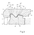
- the contact surfaces 16 of the weapon barrel 1 adjacent first stage 12 of the closure wedge 9 and the contact surfaces 18 of the corresponding first recesses 14 of the side parts 3, 4 each have a positive slope with the inclination angles ⁇ 1 and ⁇ 1 (in the order of eg 10 °)
- the angles of inclination ⁇ 1 and ⁇ 2 of the abutment surfaces 16, 17 of the steps 12, 13 of the closure wedge 9 and the inclination angles ⁇ 1 and ⁇ 2 of the abutment surfaces 18, 19 of the recesses 14, 15 differ in the illustrated embodiment, so that In the load-free state between the contact surfaces 16, 17 of the steps 12, 13 and the contact surfaces 18, 19 of the recesses 14, 15 there is only one linear contact. Only with increasing load at firing then the corresponding contact surfaces 16, 17, 18, 19 of the stages 12, 13 and depressions 14, 15 are uniformly pressed against each other, so that a metronanpressung is avoided under load and thereby the risk of wear is reduced.
- the contact surfaces 17 of the second stage 13 at a load first come to rest against the complementary contact surfaces 19 of the second recess 15 of the bottom piece 2 and by the elastic deformation during further loading under the fire action then the contact surfaces 16 of the first stage 12 completely flat in terms of contact with the complementary contact surfaces 18 of the first recess 14 of the bottom piece 2 come.
Landscapes
- Engineering & Computer Science (AREA)
- General Engineering & Computer Science (AREA)
- Aiming, Guidance, Guns With A Light Source, Armor, Camouflage, And Targets (AREA)
- Toys (AREA)
- Clamps And Clips (AREA)
- Mutual Connection Of Rods And Tubes (AREA)
- Cylinder Crankcases Of Internal Combustion Engines (AREA)
- Joining Of Building Structures In Genera (AREA)
- Dowels (AREA)
Abstract
Description
- Die Erfindung betrifft einen Keilverschluß für eine Rohrwaffe mit einem an einem Waffenrohr heckseitig angeordneten Bodenstück und einem in einer Ausnehmung des Bodenstückes senkrecht zur Seelenachse des Waffenrohres verschiebbaren Verschlußkeil.
- Ein derartiger Keilverschluß ist beispielsweise aus der US 898,840 sowie aus der DE 198 23 785 A1 bekannt. Dabei weist der jeweilige Verschlußkeil an seinen gegenüberliegenden Seitenflächen, in Richtung der Seelenachse des Waffenrohres gesehen, mehrere hintereinander angeordnete sägezahnförmige Stufen auf, die in entsprechende Vertiefungen der Seitenwände der Ausnehmung des Bodenstückes eingreifen, so daß sich bei Schußabgabe die dem Waffenrohr abgewandten, als Anlageflächen ausgebildeten Seiten der Stufen des Verschlußkeiles an korrespondierenden Anlageflächen der Vertiefungen der Seitenwände des Bodenstückes abstützen. Die Anlageflächen der einzelnen Stufen des Verschlußkeiles und die Anlageflächen der korrespondierenden Vertiefungen der Seitenwände weisen bei den bekannten Keilverschlüssen im wesentlichen alle die gleiche Neigungsrichtung auf.
- Aus der US 5,014,592 ist ferner ein Keilverschluß bekannt, dessen Verschlußkeil drei sägezahnförmige Stufen aufweist, die derart in bezug auf die korrespondierenden Anlageflächen der Vertiefungen der Seitenwände des Bodenstückes angeordnet sind, daß bei Schußabgabe zunächst die Anlageflächen der beiden gegenüberliegenden heckseitigen Stufen des Verschlußkeiles an den korrespondierenden Anlageflächen des Bodenstückes anliegen und erst mit zunehmendem Druck auch die Anlageflächen der weiteren Stufen gegen die korrespondierenden Anlageflächen der Bodenstücke gepreßt werden. Hierzu weisen die Anlageflächen der einzelnen nebeneinander angeordneten Stufen unterschiedliche Flankenwinkel auf, die allerdings mit den Flankenwinkel der korrespondierenden Anlageflächen der Vertiefungen des Bodenstückes übereinstimmen. Auch bei diesem Verschlußkeil weisen die einzelnen Stufen im wesentlichen alle die gleiche, nämlich positive Neigungsrichtung (wenn man entlang der Seelenachse zur Mündung des Waffenrohres hin sieht) auf.
- Ferner offenbart die US 5,014,592 einen Verschlußkeil, an dem heckseitig ein in das Bodenstück einschiebbarer Steg befestigt ist, welcher die beiden Seiten des Bodenstückes (Bodenstückwangen) miteinander verbindet und bei Schußabgabe am Aufweiten hindert.
- Ausgehend von der US 5,014,592 liegt der Erfindung die Aufgabe zugrunde, eine gegenüber bekannten Keilverschlüssen optimalere Kraftverteilung innerhalb des Bodenstückes bei Schußabgabe zu erreichen und damit die spannungsmäßige Höchstbelastung zu optimieren.
- Diese Aufgabe wird erfindungsgemäß durch die Merkmale des Anspruchs 1 gelöst. Weitere, besonders vorteilhafte Ausgestaltungen der Erfindung offenbaren die Unteransprüche.
- Die Erfindung beruht im wesentlichen auf dem Gedanken, einen Keilverschluß vorzusehen, dessen Verschlußkeil mindestens zwei axial hintereinander angeordnete Stufen aufweist, wobei die Anlagefläche der dem Waffenrohr benachbarten ersten Stufe eine positive und die Anlagefläche der zweiten Stufe eine negative Neigungsrichtung besitzen. Die Neigungsrichtungen der Anlageflächen der den Stufen korrespondierenden Vertiefungen der Seitenwände des Bodenstückes entsprechen den Neigungsrichtungen der Anlageflächen der beiden Stufen.
- Als vorteilhaft hat es sich erwiesen, wenn die Neigungswinkel der Anlageflächen der Stufen des Verschlußkeiles zwischen 8 und 12° liegen.
- Bei einer Ausführungsform der Erfindung sind die Neigungswinkel der Anlageflächen der beiden Stufen des Verschlußkeiles und die Neigungswinkel der Anlageflächen der Vertiefungen derart gewählt, daß bei einer Schußabgabe zunächst die Anlageflächen der zweiten Stufe und der korrespondierenden Vertiefungen des Bodenstückes zur Anlage kommen und durch die elastische Verformung während der weiteren Belastung unter der Schußeinwirkung dann die Anlageflächen der ersten Stufe und der korrespondierenden Vertiefungen des Bodenstückes komplett flächenmäßig ganz zur Anlage kommen.
- Bei einer weiteren Ausführungsform der Erfindung sind die Seitenwände der Ausnehmung des Bodenstückes heckseitig fest über einen Steg miteinander verbunden, so daß bei Schußabgabe eine Aufweitung der Bodenstückwangen unmittelbar bei Krafteinleitung in die Wangen verringert wird. Dabei wird der Steg durch die Verwendung der negativen Neigung der Anlageflächen der zweiten Stufe und der korrespondierenden Anlageflächen der Vertiefung zugentlastet.
- Weitere Einzelheiten und Vorteile der Erfindung ergeben sich aus den folgenden anhand von Figuren erläuterten Ausführungsbeispielen. Es zeigen:
- Fig.1 eine perspektivische Ansicht des Bodenstückes einer großkalibrigen Waffe mit erfindungsgemäßem Keilverschluß ohne Verschlußkeil;
- Fig.2 den für den in Fig.1 dargestellten Keilverschluß bestimmten Verschlußkeil und
- Fig.3 einen vergrößerten Längsschnitt des in Fig.1 dargestellten Keilverschlusses mit Verschlußkeil vor einer Druckbelastung.
- In Fig.1 ist mit 1 ein Waffenrohr bezeichnet, an dem heckseitig in an sich bekannter Weise ein Bodenstück 2 befestigt ist. Das Bodenstück 2 ist zum hinteren Ende hin gabelförmig ausgebildet und weist zwei Seitenteile (Bodenstückwangen) 3, 4 auf, welche mittels eines oberen Steges 5 oder eines (gestrichelt angedeuteten) unteren Steges 6 fest miteinander verbunden sind. Die Seitenteile 3, 4 und der Steg 5 oder 6 des Bodenstückes 2 begrenzen eine Ausnehmung 7, in welcher senkrecht zur Seelenachse 8 des Waffenrohres 1 ein Verschlußkeil 9 (Fig.2) verschiebbar anordbar ist.
- Der Verschlußkeil 9 weist auf jeder seiner Seiten 10, 11, in Richtung der Seelenachse 8 gesehen, zwei hintereinander angeordnete, seitlich vorstehende Stufen 12, 13 auf, die in entsprechende Vertiefungen 14, 15 der Seitenteile 3, 4 des Bodenstückes 2 eingreifen. Bei Schußabgabe stützen sich daher die dem Waffenrohr 1 abgewandten, als Anlageflächen 16, 17 ausgebildeten Seiten der Stufen 12, 13 des Verschlußkeiles 9 an korrespondierenden Anlageflächen 18, 19 der Vertiefungen 14, 15 der Seitenteile 3, 4 des Bodenstückes 2 ab. Dabei weisen die Anlageflächen 16 der dem Waffenrohr 1 benachbarten ersten Stufe 12 des Verschlußkeiles 9 und die Anlageflächen 18 der korrespondierenden ersten Vertiefungen 14 der Seitenteile 3, 4 jeweils eine positive Neigung mit den Neigungswinkeln α1 und β1 (in der Größenordnung von z.B. 10°) auf. Die Anlageflächen 17 der zweiten Stufe 13 des Verschlußkeiles 9 und die Anlageflächen 19 der korrespondierenden zweiten Vertiefungen 15 der Seitenteile 3, 4 weisen hingegen jeweils eine negative Neigung mit den Neigungswinkeln α2, und β2 (von z.B. ebenfalls ca. 10°) auf.
- Wie Fig.3 entnehmbar ist, unterscheiden sich die Neigungswinkel α1 und α2 der Anlageflächen 16, 17 der Stufen 12, 13 des Verschlußkeiles 9 und der Neigungswinkel β1 und β2 der Anlageflächen 18, 19 der Vertiefungen 14, 15 in dem dargestellten Ausführungsbeispiel, so daß im lastfreien Zustand zwischen den Anlageflächen 16, 17 der Stufen 12, 13 und den Anlageflächen 18, 19 der Vertiefungen 14, 15 jeweils nur ein linienförmiger Kontakt vorliegt. Erst mit zunehmender Last bei Schußabgabe werden dann die entsprechenden Anlageflächen 16, 17, 18, 19 der Stufen 12, 13 und Vertiefungen 14, 15 gleichmäßig gegeneinander gepreßt, so daß eine Linienanpressung bei Belastung vermieden wird und dadurch die Gefahr eines Verschleißes reduziert wird.
- Ferner kann vorgesehen sein, daß die Anlageflächen 17 der zweiten Stufe 13 bei einer Belastung zuerst zur Anlage an die komplementäre Anlageflächen 19 der zweiten Vertiefung 15 des Bodenstückes 2 kommen und durch die elastische Verformung während der Weiterbelastung unter der Schußeinwirkung dann die Anlageflächen 16 der ersten Stufe 12 vollständig flächenmäßig zur Anlage an die komplementäre Anlageflächen 18 der ersten Vertiefung 14 des Bodenstückes 2 kommen.
-
- 1
- Waffenrohr
- 2
- Bodenstück
- 3,4
- Seitenteile
- 5,6
- Stege
- 7
- Ausnehmung
- 8
- Seelenachse
- 9
- Verschlußkeil
- 10,11
- Seiten (Verschlußkeil)
- 12
- (erste) Stufe
- 13
- (zweite) Stufe
- 14
- (erste) Vertiefung
- 15
- (zweite) Vertiefung
- 16,17
- Anlageflächen (der Stufen)
- 18,19
- Anlageflächen (der Vertiefungen)
- α1, α2
- Neigungswinkel der Anlageflächen der Stufen
- β1, β2
- Neigungswinkel der Anlageflächen der Vertiefungen
Claims (5)
- Keilverschluß für eine Rohrwaffe mit einem an einem Waffenrohr (1) heckseitig angeordneten Bodenstück (2) und einem in einer Ausnehmung (7) des Bodenstückes (2) senkrecht zur Seelenachse (8) des Waffenrohres (1) verschiebbaren Verschlußkeil (9), mit den Merkmalen:a) in Richtung der Seelenachse (8) des Waffenrohres (1) weist der Verschlußkeil (9) mindestens zwei hintereinander angeordnete, seitlich vorstehende Stufen (12, 13) auf, die in entsprechende Vertiefungen (14, 15) der Seitenteile (3, 4) der Ausnehmung (7) des Bodenstückes (2) eingreifen, so daß sich bei Schußabgabe die dem Waffenrohr (1) abgewandten, als Anlageflächen (16, 17) ausgebildeten Seiten der Stufen (12, 13) des Verschlußkeiles (9) an korrespondierenden Anlageflächen (18, 19) der Vertiefungen (14, 15) der Seitenteile (3, 4) des Bodenstückes (2) abstützen;b) die Anlageflächen (16) der dem Waffenrohr (1) benachbarten erste Stufe (12) des Verschlußkeiles (9) und die Anlageflächen (18) der korrespondierenden ersten Vertiefungen (14) der Seitenteile (3, 4) weisen jeweils eine positive Neigung auf;c) die Anlageflächen (17) der zweiten Stufe (13) des Verschlußkeiles (9) und die Anlageflächen (19) der korrespondierenden zweiten Vertiefungen (15) der Seitenteile (3, 4) weisen jeweils eine negative Neigung auf.
- Keilverschluß nach Anspruch 1, dadurch gekennzeichnet, daß die Neigungswinkel (α1, α2) der Anlageflächen (16, 17) der Stufen (12, 13) des Verschlußkeiles (9) zwischen 8 und 12° liegen.
- Keilverschluß nach Anspruch 1 oder 2, dadurch gekennzeichnet, daß die Neigungswinkel (α1, α2) der Anlageflächen (16, 17) der Stufen (12, 13) des Verschlußkeiles (9) und die Neigungswinkel (β1, β2) der Anlageflächen (18, 19) der Vertiefungen (14, 15) unterschiedlich sind.
- Keilverschluß nach einem der Ansprüche 1 bis 3, dadurch gekennzeichnet, daß die Neigungswinkel (α1, α2) der Anlageflächen (16, 17) der Stufen (12, 13) des Verschlußkeiles (9) und die Neigungswinkel (β1, β2) der Anlageflächen (18, 19) der Vertiefungen (14, 15) derart gewählt sind, daß bei Schußabgabe zunächst die Anlageflächen (17) der zweiten Stufe (13) und die Anlageflächen (19) der korrespondierenden zweiten Vertiefungen (15) des Bodenstückes (2) zur Anlage kommen und durch die elastische Verformung während der weiteren Belastung unter der Schußeinwirkung dann die Anlageflächen (16) der ersten Stufe (12) und die Anlagefläche (18) der korrespondierenden ersten Vertiefungen (14) des Bodenstückes (2) flächenmäßig vollständig zur Anlage kommen.
- Keilverschluß nach einem der Ansprüche 1 bis 4, dadurch gekennzeichnet, daß die Seitenteile (3, 4) der Ausnehmung (7) des Bodenstückes (2) heckseitig fest über einen Steg (5, 6) miteinander verbunden sind.
Applications Claiming Priority (1)
| Application Number | Priority Date | Filing Date | Title |
|---|---|---|---|
| DE102004052550A DE102004052550A1 (de) | 2004-10-29 | 2004-10-29 | Keilverschluß für eine Rohrwaffe |
Publications (2)
| Publication Number | Publication Date |
|---|---|
| EP1653188A1 true EP1653188A1 (de) | 2006-05-03 |
| EP1653188B1 EP1653188B1 (de) | 2007-06-20 |
Family
ID=35565483
Family Applications (1)
| Application Number | Title | Priority Date | Filing Date |
|---|---|---|---|
| EP05017573A Expired - Lifetime EP1653188B1 (de) | 2004-10-29 | 2005-08-12 | Keilverschluss für eine Rohrwaffe |
Country Status (5)
| Country | Link |
|---|---|
| EP (1) | EP1653188B1 (de) |
| JP (1) | JP4782530B2 (de) |
| AT (1) | ATE365304T1 (de) |
| DE (2) | DE102004052550A1 (de) |
| ES (1) | ES2286746T3 (de) |
Families Citing this family (6)
| Publication number | Priority date | Publication date | Assignee | Title |
|---|---|---|---|---|
| DE102007003142B4 (de) * | 2007-01-16 | 2014-09-25 | Rheinmetall Waffe Munition Gmbh | Sicherungseinrichtung zum Verhindern des unbeabsichtigten Verschließens eines in seiner geöffneten Position befindlichen Verschlusskeiles einer Rohrwaffe |
| DE102009011939B4 (de) | 2009-03-10 | 2015-11-26 | Rheinmetall Waffe Munition Gmbh | Verriegelungsvorrichtung für einen Verschluss |
| DE102009049442B3 (de) * | 2009-10-14 | 2011-05-26 | Rheinmetall Waffe Munition Gmbh | Verriegelung mit angepasster Kontur für ein Verschlusssystem insbesondere einer Mittelkaliberwaffe |
| DE102019122290B3 (de) | 2019-08-20 | 2021-02-25 | Rheinmetall Waffe Munition Gmbh | Verschlusssystem und Rohrwaffe |
| DE102019122296A1 (de) | 2019-08-20 | 2021-06-17 | Rheinmetall Waffe Munition Gmbh | Verschluss und Rohrwaffe |
| DE102020108551A1 (de) | 2020-03-27 | 2021-09-30 | Rheinmetall Waffe Munition Gmbh | Waffenrohrverschluss und Rohrwaffe |
Citations (7)
| Publication number | Priority date | Publication date | Assignee | Title |
|---|---|---|---|---|
| DE24611C (de) * | TH. NORDENFELT .in London | Rohrverschlufs für Geschütze kleinen Kalibers | ||
| DE242131C (de) * | 1910-09-09 | |||
| US898840A (en) | 1906-09-27 | 1908-09-15 | Vickers Sons & Maxim Ltd | Breech mechanism of guns. |
| US5014592A (en) | 1990-01-02 | 1991-05-14 | The United States Of America As Represented By The Secretary Of The Army | Multi-lug breech mechanism |
| US5604325A (en) * | 1995-05-11 | 1997-02-18 | Giat Industries | Cannon breech including a breech block translatable between two cheeks of a breech ring, and cannon having such a cannon breech |
| DE19823785A1 (de) | 1998-05-28 | 1999-12-02 | Rheinmetall W & M Gmbh | Vertikalkeilverschluß für eine großkalibrige Waffe |
| US20030051600A1 (en) * | 2001-09-20 | 2003-03-20 | Breuer Heinz Gunter | Weapon |
-
2004
- 2004-10-29 DE DE102004052550A patent/DE102004052550A1/de not_active Withdrawn
-
2005
- 2005-08-12 AT AT05017573T patent/ATE365304T1/de not_active IP Right Cessation
- 2005-08-12 EP EP05017573A patent/EP1653188B1/de not_active Expired - Lifetime
- 2005-08-12 DE DE502005000892T patent/DE502005000892D1/de not_active Expired - Lifetime
- 2005-08-12 ES ES05017573T patent/ES2286746T3/es not_active Expired - Lifetime
- 2005-10-11 JP JP2005296405A patent/JP4782530B2/ja not_active Expired - Fee Related
Patent Citations (7)
| Publication number | Priority date | Publication date | Assignee | Title |
|---|---|---|---|---|
| DE24611C (de) * | TH. NORDENFELT .in London | Rohrverschlufs für Geschütze kleinen Kalibers | ||
| US898840A (en) | 1906-09-27 | 1908-09-15 | Vickers Sons & Maxim Ltd | Breech mechanism of guns. |
| DE242131C (de) * | 1910-09-09 | |||
| US5014592A (en) | 1990-01-02 | 1991-05-14 | The United States Of America As Represented By The Secretary Of The Army | Multi-lug breech mechanism |
| US5604325A (en) * | 1995-05-11 | 1997-02-18 | Giat Industries | Cannon breech including a breech block translatable between two cheeks of a breech ring, and cannon having such a cannon breech |
| DE19823785A1 (de) | 1998-05-28 | 1999-12-02 | Rheinmetall W & M Gmbh | Vertikalkeilverschluß für eine großkalibrige Waffe |
| US20030051600A1 (en) * | 2001-09-20 | 2003-03-20 | Breuer Heinz Gunter | Weapon |
Also Published As
| Publication number | Publication date |
|---|---|
| JP4782530B2 (ja) | 2011-09-28 |
| ATE365304T1 (de) | 2007-07-15 |
| DE502005000892D1 (de) | 2007-08-02 |
| DE102004052550A1 (de) | 2006-05-04 |
| JP2006125832A (ja) | 2006-05-18 |
| EP1653188B1 (de) | 2007-06-20 |
| ES2286746T3 (es) | 2007-12-01 |
Similar Documents
| Publication | Publication Date | Title |
|---|---|---|
| DE102009053966A1 (de) | Anordnung und Verfahren zum Verbinden eines Zubehörteils mit einem Operationstisch | |
| DE2008035B2 (de) | Blindniet | |
| EP1653188B1 (de) | Keilverschluss für eine Rohrwaffe | |
| EP4027099B1 (de) | Feuerwahleinheit für eine schusswaffe | |
| EP3423224B1 (de) | Elektrisches handkernbohrgerät | |
| EP2179191A1 (de) | Kupplungsglied für eine mitnehmerkupplung und herstellungsverfahren | |
| DE102016105945A1 (de) | Verfahren zur Herstellung eines Spitzbohrers für das Schreinerhandwerk | |
| WO2002053933A1 (de) | Kolbenbefestigung | |
| EP4299426B1 (de) | Antriebsanordnung | |
| DE102021202473A1 (de) | Antriebsanordnung | |
| EP4560250A1 (de) | Schnell aus dem gehäuseunterteil von waffen des typs ar aus- und einbaubarer abzug | |
| EP1743826A1 (de) | Lenkgetriebe für ein Fahrzeug | |
| DE102015203895A1 (de) | Nockenwellenbaugruppe | |
| DE10291501T5 (de) | Lager für ein mechanisches Wälzübertragungselement | |
| EP3599385A1 (de) | Kugelsperrbolzen mit kopfnaher arretierung | |
| EP1421263B1 (de) | Lösbare verbindung zum kuppeln eines gaswechselventils einer brennkraftmaschine mit einem aktor | |
| EP1122032B1 (de) | Spannfutter für Schaftenden von Werkzeugseinsatzstücken, insbesondere Schraubendreherbits | |
| WO2008141736A1 (de) | Vorrichtung und verfahren zur befestigung einer mündungsbremse an einem waffenrohr | |
| DE19509909C2 (de) | Verbindungsanordnung | |
| AT500716A1 (de) | Verfahren zur ausgestaltung eines verbindungselementes und verbindungselement | |
| DE2214466A1 (de) | Aus einem Schraubenzieher und Schraubengreifer bestehendes kombiniertes Werkzeug | |
| DE10223306B4 (de) | Gehäuse zur Aufnahme eines Lagerbauteiles und Verfahren zu dessen Herstellung | |
| DE10004975C2 (de) | Mehrstufiges hydraulisches Druckbegrenzungsventil | |
| WO1997002927A1 (de) | Schraubendreherbit | |
| EP3979438A1 (de) | Presswerkzeug |
Legal Events
| Date | Code | Title | Description |
|---|---|---|---|
| PUAI | Public reference made under article 153(3) epc to a published international application that has entered the european phase |
Free format text: ORIGINAL CODE: 0009012 |
|
| AK | Designated contracting states |
Kind code of ref document: A1 Designated state(s): AT BE BG CH CY CZ DE DK EE ES FI FR GB GR HU IE IS IT LI LT LU LV MC NL PL PT RO SE SI SK TR |
|
| AX | Request for extension of the european patent |
Extension state: AL BA HR MK YU |
|
| 17P | Request for examination filed |
Effective date: 20060517 |
|
| 17Q | First examination report despatched |
Effective date: 20060713 |
|
| GRAP | Despatch of communication of intention to grant a patent |
Free format text: ORIGINAL CODE: EPIDOSNIGR1 |
|
| AKX | Designation fees paid |
Designated state(s): AT BE BG CH CY CZ DE DK EE ES FI FR GB GR HU IE IS IT LI LT LU LV MC NL PL PT RO SE SI SK TR |
|
| GRAS | Grant fee paid |
Free format text: ORIGINAL CODE: EPIDOSNIGR3 |
|
| GRAA | (expected) grant |
Free format text: ORIGINAL CODE: 0009210 |
|
| AK | Designated contracting states |
Kind code of ref document: B1 Designated state(s): AT BE BG CH CY CZ DE DK EE ES FI FR GB GR HU IE IS IT LI LT LU LV MC NL PL PT RO SE SI SK TR |
|
| REG | Reference to a national code |
Ref country code: GB Ref legal event code: FG4D Free format text: NOT ENGLISH |
|
| REG | Reference to a national code |
Ref country code: CH Ref legal event code: EP |
|
| REG | Reference to a national code |
Ref country code: IE Ref legal event code: FG4D Free format text: LANGUAGE OF EP DOCUMENT: GERMAN |
|
| REG | Reference to a national code |
Ref country code: CH Ref legal event code: NV Representative=s name: OK PAT AG PATENTE MARKEN LIZENZEN |
|
| REF | Corresponds to: |
Ref document number: 502005000892 Country of ref document: DE Date of ref document: 20070802 Kind code of ref document: P |
|
| PG25 | Lapsed in a contracting state [announced via postgrant information from national office to epo] |
Ref country code: SE Free format text: LAPSE BECAUSE OF FAILURE TO SUBMIT A TRANSLATION OF THE DESCRIPTION OR TO PAY THE FEE WITHIN THE PRESCRIBED TIME-LIMIT Effective date: 20070920 |
|
| GBT | Gb: translation of ep patent filed (gb section 77(6)(a)/1977) |
Effective date: 20070926 |
|
| ET | Fr: translation filed | ||
| PG25 | Lapsed in a contracting state [announced via postgrant information from national office to epo] |
Ref country code: PL Free format text: LAPSE BECAUSE OF FAILURE TO SUBMIT A TRANSLATION OF THE DESCRIPTION OR TO PAY THE FEE WITHIN THE PRESCRIBED TIME-LIMIT Effective date: 20070620 |
|
| REG | Reference to a national code |
Ref country code: ES Ref legal event code: FG2A Ref document number: 2286746 Country of ref document: ES Kind code of ref document: T3 |
|
| NLV1 | Nl: lapsed or annulled due to failure to fulfill the requirements of art. 29p and 29m of the patents act | ||
| REG | Reference to a national code |
Ref country code: IE Ref legal event code: FD4D |
|
| PG25 | Lapsed in a contracting state [announced via postgrant information from national office to epo] |
Ref country code: IE Free format text: LAPSE BECAUSE OF FAILURE TO SUBMIT A TRANSLATION OF THE DESCRIPTION OR TO PAY THE FEE WITHIN THE PRESCRIBED TIME-LIMIT Effective date: 20070620 Ref country code: NL Free format text: LAPSE BECAUSE OF FAILURE TO SUBMIT A TRANSLATION OF THE DESCRIPTION OR TO PAY THE FEE WITHIN THE PRESCRIBED TIME-LIMIT Effective date: 20070620 Ref country code: BG Free format text: LAPSE BECAUSE OF FAILURE TO SUBMIT A TRANSLATION OF THE DESCRIPTION OR TO PAY THE FEE WITHIN THE PRESCRIBED TIME-LIMIT Effective date: 20070920 Ref country code: CZ Free format text: LAPSE BECAUSE OF FAILURE TO SUBMIT A TRANSLATION OF THE DESCRIPTION OR TO PAY THE FEE WITHIN THE PRESCRIBED TIME-LIMIT Effective date: 20070620 Ref country code: PT Free format text: LAPSE BECAUSE OF FAILURE TO SUBMIT A TRANSLATION OF THE DESCRIPTION OR TO PAY THE FEE WITHIN THE PRESCRIBED TIME-LIMIT Effective date: 20071120 Ref country code: SI Free format text: LAPSE BECAUSE OF FAILURE TO SUBMIT A TRANSLATION OF THE DESCRIPTION OR TO PAY THE FEE WITHIN THE PRESCRIBED TIME-LIMIT Effective date: 20070620 Ref country code: IS Free format text: LAPSE BECAUSE OF FAILURE TO SUBMIT A TRANSLATION OF THE DESCRIPTION OR TO PAY THE FEE WITHIN THE PRESCRIBED TIME-LIMIT Effective date: 20071020 |
|
| BERE | Be: lapsed |
Owner name: RHEINMETALL WAFFE MUNITION G.M.B.H. Effective date: 20070831 |
|
| PG25 | Lapsed in a contracting state [announced via postgrant information from national office to epo] |
Ref country code: LV Free format text: LAPSE BECAUSE OF FAILURE TO SUBMIT A TRANSLATION OF THE DESCRIPTION OR TO PAY THE FEE WITHIN THE PRESCRIBED TIME-LIMIT Effective date: 20070620 Ref country code: SK Free format text: LAPSE BECAUSE OF FAILURE TO SUBMIT A TRANSLATION OF THE DESCRIPTION OR TO PAY THE FEE WITHIN THE PRESCRIBED TIME-LIMIT Effective date: 20070620 Ref country code: LT Free format text: LAPSE BECAUSE OF FAILURE TO SUBMIT A TRANSLATION OF THE DESCRIPTION OR TO PAY THE FEE WITHIN THE PRESCRIBED TIME-LIMIT Effective date: 20070620 |
|
| PLBE | No opposition filed within time limit |
Free format text: ORIGINAL CODE: 0009261 |
|
| STAA | Information on the status of an ep patent application or granted ep patent |
Free format text: STATUS: NO OPPOSITION FILED WITHIN TIME LIMIT |
|
| PG25 | Lapsed in a contracting state [announced via postgrant information from national office to epo] |
Ref country code: GR Free format text: LAPSE BECAUSE OF FAILURE TO SUBMIT A TRANSLATION OF THE DESCRIPTION OR TO PAY THE FEE WITHIN THE PRESCRIBED TIME-LIMIT Effective date: 20070921 Ref country code: DK Free format text: LAPSE BECAUSE OF FAILURE TO SUBMIT A TRANSLATION OF THE DESCRIPTION OR TO PAY THE FEE WITHIN THE PRESCRIBED TIME-LIMIT Effective date: 20070620 Ref country code: MC Free format text: LAPSE BECAUSE OF NON-PAYMENT OF DUE FEES Effective date: 20070831 |
|
| 26N | No opposition filed |
Effective date: 20080325 |
|
| PG25 | Lapsed in a contracting state [announced via postgrant information from national office to epo] |
Ref country code: RO Free format text: LAPSE BECAUSE OF FAILURE TO SUBMIT A TRANSLATION OF THE DESCRIPTION OR TO PAY THE FEE WITHIN THE PRESCRIBED TIME-LIMIT Effective date: 20070620 |
|
| PG25 | Lapsed in a contracting state [announced via postgrant information from national office to epo] |
Ref country code: BE Free format text: LAPSE BECAUSE OF NON-PAYMENT OF DUE FEES Effective date: 20070831 |
|
| PG25 | Lapsed in a contracting state [announced via postgrant information from national office to epo] |
Ref country code: AT Free format text: LAPSE BECAUSE OF NON-PAYMENT OF DUE FEES Effective date: 20070812 |
|
| PG25 | Lapsed in a contracting state [announced via postgrant information from national office to epo] |
Ref country code: EE Free format text: LAPSE BECAUSE OF FAILURE TO SUBMIT A TRANSLATION OF THE DESCRIPTION OR TO PAY THE FEE WITHIN THE PRESCRIBED TIME-LIMIT Effective date: 20070620 |
|
| PG25 | Lapsed in a contracting state [announced via postgrant information from national office to epo] |
Ref country code: FI Free format text: LAPSE BECAUSE OF FAILURE TO SUBMIT A TRANSLATION OF THE DESCRIPTION OR TO PAY THE FEE WITHIN THE PRESCRIBED TIME-LIMIT Effective date: 20070620 |
|
| PG25 | Lapsed in a contracting state [announced via postgrant information from national office to epo] |
Ref country code: CY Free format text: LAPSE BECAUSE OF FAILURE TO SUBMIT A TRANSLATION OF THE DESCRIPTION OR TO PAY THE FEE WITHIN THE PRESCRIBED TIME-LIMIT Effective date: 20070620 |
|
| PG25 | Lapsed in a contracting state [announced via postgrant information from national office to epo] |
Ref country code: LU Free format text: LAPSE BECAUSE OF NON-PAYMENT OF DUE FEES Effective date: 20070812 |
|
| PG25 | Lapsed in a contracting state [announced via postgrant information from national office to epo] |
Ref country code: HU Free format text: LAPSE BECAUSE OF FAILURE TO SUBMIT A TRANSLATION OF THE DESCRIPTION OR TO PAY THE FEE WITHIN THE PRESCRIBED TIME-LIMIT Effective date: 20071221 |
|
| REG | Reference to a national code |
Ref country code: FR Ref legal event code: PLFP Year of fee payment: 12 |
|
| REG | Reference to a national code |
Ref country code: FR Ref legal event code: PLFP Year of fee payment: 13 |
|
| REG | Reference to a national code |
Ref country code: FR Ref legal event code: PLFP Year of fee payment: 14 |
|
| REG | Reference to a national code |
Ref country code: CH Ref legal event code: PFUS Owner name: RHEINMETALL WAFFE MUNITION GMBH, DE Free format text: FORMER OWNER: RHEINMETALL WAFFE MUNITION GMBH, DE |
|
| REG | Reference to a national code |
Ref country code: DE Ref legal event code: R082 Ref document number: 502005000892 Country of ref document: DE Representative=s name: DREISS PATENTANWAELTE PARTG MBB, DE |
|
| REG | Reference to a national code |
Ref country code: DE Ref legal event code: R082 Ref document number: 502005000892 Country of ref document: DE Representative=s name: DREISS PATENTANWAELTE PARTG MBB, DE |
|
| PGFP | Annual fee paid to national office [announced via postgrant information from national office to epo] |
Ref country code: TR Payment date: 20230811 Year of fee payment: 19 Ref country code: IT Payment date: 20230825 Year of fee payment: 19 Ref country code: GB Payment date: 20230824 Year of fee payment: 19 Ref country code: CH Payment date: 20230902 Year of fee payment: 19 |
|
| PGFP | Annual fee paid to national office [announced via postgrant information from national office to epo] |
Ref country code: FR Payment date: 20230822 Year of fee payment: 19 Ref country code: DE Payment date: 20230821 Year of fee payment: 19 |
|
| PGFP | Annual fee paid to national office [announced via postgrant information from national office to epo] |
Ref country code: ES Payment date: 20231027 Year of fee payment: 19 |
|
| REG | Reference to a national code |
Ref country code: DE Ref legal event code: R119 Ref document number: 502005000892 Country of ref document: DE |
|
| REG | Reference to a national code |
Ref country code: CH Ref legal event code: PL |
|
| GBPC | Gb: european patent ceased through non-payment of renewal fee |
Effective date: 20240812 |
|
| PG25 | Lapsed in a contracting state [announced via postgrant information from national office to epo] |
Ref country code: CH Free format text: LAPSE BECAUSE OF NON-PAYMENT OF DUE FEES Effective date: 20240831 |
|
| PG25 | Lapsed in a contracting state [announced via postgrant information from national office to epo] |
Ref country code: DE Free format text: LAPSE BECAUSE OF NON-PAYMENT OF DUE FEES Effective date: 20250301 |
|
| PG25 | Lapsed in a contracting state [announced via postgrant information from national office to epo] |
Ref country code: GB Free format text: LAPSE BECAUSE OF NON-PAYMENT OF DUE FEES Effective date: 20240812 |
|
| PG25 | Lapsed in a contracting state [announced via postgrant information from national office to epo] |
Ref country code: IT Free format text: LAPSE BECAUSE OF NON-PAYMENT OF DUE FEES Effective date: 20240812 |
|
| PG25 | Lapsed in a contracting state [announced via postgrant information from national office to epo] |
Ref country code: FR Free format text: LAPSE BECAUSE OF NON-PAYMENT OF DUE FEES Effective date: 20240831 |
|
| REG | Reference to a national code |
Ref country code: ES Ref legal event code: FD2A Effective date: 20250930 |
|
| PG25 | Lapsed in a contracting state [announced via postgrant information from national office to epo] |
Ref country code: ES Free format text: LAPSE BECAUSE OF NON-PAYMENT OF DUE FEES Effective date: 20240813 |
|
| PG25 | Lapsed in a contracting state [announced via postgrant information from national office to epo] |
Ref country code: TR Free format text: LAPSE BECAUSE OF NON-PAYMENT OF DUE FEES Effective date: 20240812 |