EP1652748A1 - Arbre telescopique destine a la direction d'un vehicule a moteur - Google Patents
Arbre telescopique destine a la direction d'un vehicule a moteur Download PDFInfo
- Publication number
- EP1652748A1 EP1652748A1 EP04746089A EP04746089A EP1652748A1 EP 1652748 A1 EP1652748 A1 EP 1652748A1 EP 04746089 A EP04746089 A EP 04746089A EP 04746089 A EP04746089 A EP 04746089A EP 1652748 A1 EP1652748 A1 EP 1652748A1
- Authority
- EP
- European Patent Office
- Prior art keywords
- shaft
- axis
- contact portion
- groove
- transferring member
- Prior art date
- Legal status (The legal status is an assumption and is not a legal conclusion. Google has not performed a legal analysis and makes no representation as to the accuracy of the status listed.)
- Withdrawn
Links
Images


Classifications
-
- B—PERFORMING OPERATIONS; TRANSPORTING
- B62—LAND VEHICLES FOR TRAVELLING OTHERWISE THAN ON RAILS
- B62D—MOTOR VEHICLES; TRAILERS
- B62D1/00—Steering controls, i.e. means for initiating a change of direction of the vehicle
- B62D1/02—Steering controls, i.e. means for initiating a change of direction of the vehicle vehicle-mounted
- B62D1/16—Steering columns
- B62D1/18—Steering columns yieldable or adjustable, e.g. tiltable
- B62D1/185—Steering columns yieldable or adjustable, e.g. tiltable adjustable by axial displacement, e.g. telescopically
-
- F—MECHANICAL ENGINEERING; LIGHTING; HEATING; WEAPONS; BLASTING
- F16—ENGINEERING ELEMENTS AND UNITS; GENERAL MEASURES FOR PRODUCING AND MAINTAINING EFFECTIVE FUNCTIONING OF MACHINES OR INSTALLATIONS; THERMAL INSULATION IN GENERAL
- F16C—SHAFTS; FLEXIBLE SHAFTS; ELEMENTS OR CRANKSHAFT MECHANISMS; ROTARY BODIES OTHER THAN GEARING ELEMENTS; BEARINGS
- F16C29/00—Bearings for parts moving only linearly
- F16C29/005—Guide rails or tracks for a linear bearing, i.e. adapted for movement of a carriage or bearing body there along
-
- F—MECHANICAL ENGINEERING; LIGHTING; HEATING; WEAPONS; BLASTING
- F16—ENGINEERING ELEMENTS AND UNITS; GENERAL MEASURES FOR PRODUCING AND MAINTAINING EFFECTIVE FUNCTIONING OF MACHINES OR INSTALLATIONS; THERMAL INSULATION IN GENERAL
- F16C—SHAFTS; FLEXIBLE SHAFTS; ELEMENTS OR CRANKSHAFT MECHANISMS; ROTARY BODIES OTHER THAN GEARING ELEMENTS; BEARINGS
- F16C29/00—Bearings for parts moving only linearly
- F16C29/007—Hybrid linear bearings, i.e. including more than one bearing type, e.g. sliding contact bearings as well as rolling contact bearings
-
- F—MECHANICAL ENGINEERING; LIGHTING; HEATING; WEAPONS; BLASTING
- F16—ENGINEERING ELEMENTS AND UNITS; GENERAL MEASURES FOR PRODUCING AND MAINTAINING EFFECTIVE FUNCTIONING OF MACHINES OR INSTALLATIONS; THERMAL INSULATION IN GENERAL
- F16C—SHAFTS; FLEXIBLE SHAFTS; ELEMENTS OR CRANKSHAFT MECHANISMS; ROTARY BODIES OTHER THAN GEARING ELEMENTS; BEARINGS
- F16C29/00—Bearings for parts moving only linearly
- F16C29/12—Arrangements for adjusting play
- F16C29/123—Arrangements for adjusting play using elastic means
-
- F—MECHANICAL ENGINEERING; LIGHTING; HEATING; WEAPONS; BLASTING
- F16—ENGINEERING ELEMENTS AND UNITS; GENERAL MEASURES FOR PRODUCING AND MAINTAINING EFFECTIVE FUNCTIONING OF MACHINES OR INSTALLATIONS; THERMAL INSULATION IN GENERAL
- F16C—SHAFTS; FLEXIBLE SHAFTS; ELEMENTS OR CRANKSHAFT MECHANISMS; ROTARY BODIES OTHER THAN GEARING ELEMENTS; BEARINGS
- F16C3/00—Shafts; Axles; Cranks; Eccentrics
- F16C3/02—Shafts; Axles
- F16C3/03—Shafts; Axles telescopic
- F16C3/035—Shafts; Axles telescopic with built-in bearings
-
- F—MECHANICAL ENGINEERING; LIGHTING; HEATING; WEAPONS; BLASTING
- F16—ENGINEERING ELEMENTS AND UNITS; GENERAL MEASURES FOR PRODUCING AND MAINTAINING EFFECTIVE FUNCTIONING OF MACHINES OR INSTALLATIONS; THERMAL INSULATION IN GENERAL
- F16C—SHAFTS; FLEXIBLE SHAFTS; ELEMENTS OR CRANKSHAFT MECHANISMS; ROTARY BODIES OTHER THAN GEARING ELEMENTS; BEARINGS
- F16C33/00—Parts of bearings; Special methods for making bearings or parts thereof
- F16C33/30—Parts of ball or roller bearings
- F16C33/58—Raceways; Race rings
- F16C33/60—Raceways; Race rings divided or split, e.g. comprising two juxtaposed rings
-
- F—MECHANICAL ENGINEERING; LIGHTING; HEATING; WEAPONS; BLASTING
- F16—ENGINEERING ELEMENTS AND UNITS; GENERAL MEASURES FOR PRODUCING AND MAINTAINING EFFECTIVE FUNCTIONING OF MACHINES OR INSTALLATIONS; THERMAL INSULATION IN GENERAL
- F16D—COUPLINGS FOR TRANSMITTING ROTATION; CLUTCHES; BRAKES
- F16D3/00—Yielding couplings, i.e. with means permitting movement between the connected parts during the drive
- F16D3/02—Yielding couplings, i.e. with means permitting movement between the connected parts during the drive adapted to specific functions
- F16D3/06—Yielding couplings, i.e. with means permitting movement between the connected parts during the drive adapted to specific functions specially adapted to allow axial displacement
- F16D3/065—Yielding couplings, i.e. with means permitting movement between the connected parts during the drive adapted to specific functions specially adapted to allow axial displacement by means of rolling elements
-
- F—MECHANICAL ENGINEERING; LIGHTING; HEATING; WEAPONS; BLASTING
- F16—ENGINEERING ELEMENTS AND UNITS; GENERAL MEASURES FOR PRODUCING AND MAINTAINING EFFECTIVE FUNCTIONING OF MACHINES OR INSTALLATIONS; THERMAL INSULATION IN GENERAL
- F16D—COUPLINGS FOR TRANSMITTING ROTATION; CLUTCHES; BRAKES
- F16D3/00—Yielding couplings, i.e. with means permitting movement between the connected parts during the drive
- F16D3/50—Yielding couplings, i.e. with means permitting movement between the connected parts during the drive with the coupling parts connected by one or more intermediate members
- F16D3/64—Yielding couplings, i.e. with means permitting movement between the connected parts during the drive with the coupling parts connected by one or more intermediate members comprising elastic elements arranged between substantially-radial walls of both coupling parts
-
- F—MECHANICAL ENGINEERING; LIGHTING; HEATING; WEAPONS; BLASTING
- F16—ENGINEERING ELEMENTS AND UNITS; GENERAL MEASURES FOR PRODUCING AND MAINTAINING EFFECTIVE FUNCTIONING OF MACHINES OR INSTALLATIONS; THERMAL INSULATION IN GENERAL
- F16C—SHAFTS; FLEXIBLE SHAFTS; ELEMENTS OR CRANKSHAFT MECHANISMS; ROTARY BODIES OTHER THAN GEARING ELEMENTS; BEARINGS
- F16C2326/00—Articles relating to transporting
- F16C2326/20—Land vehicles
- F16C2326/24—Steering systems, e.g. steering rods or columns
Definitions
- the present invention relates to a telescopic (extensible/retractable) shaft for a vehicle steering, assembled in a steering shaft of a vehicle and constructed by fitting a male shaft and a female shaft to each other so as to be unable to rotate but to be slidable.
- a telescopic shaft of a steering mechanism unit of an automobile is performance of absorbing an axis-directional displacement occurred when the automobile travels, and not transferring the displacement and vibrations onto a steering wheel. Further, another requirement is a function of shifting a position of the steering wheel in an axis-direction and adjusting this position in order for a driver to obtain a position optimal to driving a car.
- the telescopic shaft is required to reduce backlash or rattling noises, a feeling of the backlash on the steering wheel and slide resistance occurred when performing a sliding operation in the axis-direction.
- a conventional contrivance is that metallic noises, metal butting noises, etc are absorbed or reduced by coating a male shaft of the telescopic shaft with a nylon film and applying grease over a slide portion, and the slide resistance and the backlash in a rotating direction are thus reduced.
- a rolling member and an preload elastic member for preloading a male shaft and a female shaft are interposed between an outer peripheral surface of the male shaft and an inner peripheral surface of the female shaft.
- the elastic member preloads the rolling member against the female shaft etc to such an extent as not to cause the backlash, whereby the backlash between the male shaft and the female shaft can be prevented.
- the elastic member can restrict the rolling member in a peripheral direction, and the male shaft and the female shaft can prevent their backlashes in the rotating direction thereof.
- the elastic member for preloading the rolling member and a race portion abutting on the rolling member are made from different materials and take different shapes for their usage.
- the race portion abutting on the rolling member must bear a high contact surface pressure. This implies that the torque must be transferred via the rolling member, and hence the race portion abutting on the rolling member is required to be a hard and rigid member.
- the elastic member for generating a biasing force it is required to be made from a flexible material as in the case of a spring.
- German Patent Publication DE3730393C2 exemplifies an example of a plate spring, wherein the race portion and the elastic member are made from a single material.
- the plate springs are connected via a web, so that the configuration becomes complicated, resulting in a rise in assembling cost.
- the plate spring has a difficulty in terms of utilization to make it compatible to bear the contact surface pressure of the rolling member and to give the basing force.
- Japanese Patent Application Laid-Open No.2001-193738 exemplifies an example, wherein the elastic member and the race portion are integrally formed.
- the plate spring has the difficulty in terms of utilization to make it compatible to bear the contact surface pressure of the rolling member and to give the biasing force.
- a telescopic shaft for a vehicle steering assembled in a steering shaft of a vehicle and constructed by fitting a male shaft and a female shaft to each other so as to be unable to rotate but to be slidable, the telescopic shaft comprising:
- the first torque transferring member is a rolling member rolling when both of the male shaft and the female shaft make relative movements in the axis-direction
- the second torque transferring member is a slide member sliding when both of the male shaft and the female shaft make the relative movements in the axis-direction.
- the biasing portion of the elastic member can take a bent shape bent between the transferring member sided contact portion and the groove surface sided contact portion.
- the elastic member can be constructed of an integral molding product made from thin plate spring steel.
- surface hardness of the transferring member sided contact portion can be set higher than surface hardness of a portion extending from the groove surface sided contact portion to the biasing portion.
- the biasing portion can be formed with holes for reducing a biasing force.
- a plate thickness of the transferring member sided contact portion can be set thicker than a plate thickness of a portion extending from the groove surface sided contact portion to the biasing portion.
- the transferring member sided contact portion can be formed substantially in a circular arch shape.
- a telescopic (extensible/retractable) shaft for a vehicle steering according to embodiments of the present invention will hereinafter be described with reference to the drawings.
- FIG. 1 is a side view of a steering mechanism unit of an automobile, to which the telescopic shaft for the vehicle steering according to the embodiment of the present invention is applied.
- the steering mechanism unit is constructed of an upper steering shaft portion 120 fitted via an upper bracket 101 and a lower bracket 102 to a vehicle body sided member 100 and including a steering column 103 and a steering shaft 104 rotatably held in the steering column 103, a steering wheel 105 fitted to an upper side end of the steering shaft 104, a lower steering shaft portion 107 connected via a universal joint 106 to a lower side end of the steering shaft 104, a pinion shaft 109 connected via a steering shaft coupling 108 to the lower steering shaft portion 107, a steering rack shaft 112 connected to the pinion shaft 109, and a steering rack support member 113 fixed via an elastic body 111 to another frame 110 of the vehicle body in a way that supports the steering rack shaft 112.
- the upper steering shaft portion 120 and the lower steering shaft portion 107 involve using the telescopic shaft for the vehicle steering (which will hereinafter simply be termed the telescopic shaft) according to the embodiment of the present invention.
- the lower steering shaft portion 107 is constructed by fitting a male shaft to a female shaft, and this type of lower steering shaft portion 107 is requested to have performance of absorbing displacement in an axial direction that occurs when the automobile travels and of not transmitting the displacement and vibrations onto the steering wheel 105.
- the upper steering shaft portion 120 provided on the upper portion of the steering mechanism is constructed by fitting a male shaft to the female shaft.
- This type of upper steering shaft portion 120 is, however, required to have a function of shifting a position of the steering wheel 105 in the axial direction in order to obtain a position optimal for a driver to drive the car and adjusting this position, and is therefore requested to have a function of extending and retracting in the axial direction.
- what is requested of the telescopic shaft is to reduce backlash noises at the fitting portion, a feeling of backlash on the steering wheel 105 and slide resistance caused when sliding in the axial direction.
- FIG. 2 is a vertical sectional view of the telescopic shaft for the vehicle steering according to a first embodiment of the present invention.
- FIG. 3 is a cross sectional view taken along the line X-X in FIG. 2.
- FIG. 4A is a perspective view of a plate spring according to the first embodiment.
- FIG. 4B is a perspective view of the plate spring according to a first modified example of the first embodiment.
- FIG. 4C is a perspective view of the plate spring according to a second modified example of the first embodiment.
- the telescopic shaft for the vehicle steering (which will hereinafter be simply referred to as the telescopic shaft) is constructed of a male shaft 1 and a female shaft 2 that are so fitted to each other as to be unable to rotate but to be slidable.
- the axis-directional grooves 3 of the male shaft 1 and the axis-directional grooves 5 of the female shaft 2 are interposed to be able to roll.
- the axis-directional groove 5 of the female shaft 2 takes a circular-arc shape or Gothic arch shape in section.
- the axis-directional groove 3 of the male shaft 1 is configured by a pair of flat side surfaces 3a showing line symmetry with respect to the diameter and inclined, and by a bottom surface 3b formed flat between the pair of flat side surfaces 3a.
- a plate spring 9 abutting on the spherical member 7 and thus giving a preload thereto is interposed between the axis-directional groove 3 of the male shaft 1 and the spherical member 7.
- This plate spring 9 integrally has spherical member sided contact portions 9a abutting at two points on the spherical member 7, groove surface sided contact portions 9b spaced away at a predetermined interval substantially in the peripheral direction from the respective spherical member sided contact portions 9a and abutting on the respective flat side surfaces 3a of the axis-directional groove 3 of the male shaft 1, biasing portions 9c each connecting the spherical member sided contact portion 9a and the groove surface sided contact portion 9b on the side of an outer diameter and elastically biasing the spherical member sided contact portion 9a and the groove surface sided contact portion 9b in a direction of separating the portions 9a, 9b away from each other, and a bottom portion 9d taking a face-to-face relationship with the bottom surface 3b of the axis-directional groove 3 on the side of an inner diameter.
- This biasing portion 9c takes substantially a U-shape, wherein its bottom portion is bent substantially in a circular arc shape.
- This biasing portion 9c taking the bent shape can elastically bias the spherical member sided contact portion 9a and the groove surface sided contact portion 9b so as to be separated away from each other.
- the plate spring 9 integrally has the contact portions 9a abutting on the spherical member 7 and the biasing portions 9c generating the preload, and hence it is essential to control the preload so as not to increase too much a contact surface pressure of the contact portion 9a upon the spherical member 7. Therefore, according to the first embodiment, the plate spring 9 is set to have such a structure that the preload (i.e., a load generated by the biasing portion 9c when relatively rotating the male shaft 1 around inside the female shaft 2) generated by the biasing portion 9c does not exceed an allowable value of the surface pressure caused by the contact portion 9a upon the spherical member 7.
- the preload i.e., a load generated by the biasing portion 9c when relatively rotating the male shaft 1 around inside the female shaft 2
- three lines of axis-directional grooves 4 disposed equally at an interval (phase) of 120 degrees in the peripheral direction, are formed in a way that extends on the outer peripheral surface of the male shaft 1.
- three lines of axis-directional grooves 6 disposed equally at an interval (phase) of 120 degrees in the peripheral direction, are also formed in a way that extends on the inner peripheral surface of the female shaft 2.
- axis-directional grooves 4 of the male shaft 1 and the axis-directional grooves 6 of the female shaft 2 corresponding thereto plural pieces of cylindrical rigid members 8 (which are also termed slide members or needle rollers in the present specification) sliding when the two shafts 1, 2 move relatively in the axis-direction, are interposed with a minute gap.
- cylindrical rigid members 8 which are also termed slide members or needle rollers in the present specification
- an end portion of the male shaft 1 is formed with a small-diameter portion 1a.
- This small-diameter portion 1a is provided with a stopper plate 10 regulating an axis-directional movement of the needle roller 8.
- This stopper plate 10 is constructed of an axis-directional preloading elastic member 11 consisting of a Belleville spring and a pair of flat plates 12, 13 for holding the axis-directional preloading elastic member 11 therebetween.
- the stopper plate 10 is firmly fixed by plastically deforming by clinching or caulking to the small-diameter portion 1a in a way that fits the flat plate 13, the axis-directional preloading elastic member 11 and the flat plate 12 in this sequence to the small-diameter portion 1a. In this way, the stopper plate 10 is fixed in the axis-direction.
- a fixing method of the stopper plate 10 is not limited to plastically deforming by clinching or caulking and may involve employing means such as a stopper ring, a screwing means and a push nut.
- the stopper plate 10 is so constructed as to be capable of preloading the needle roller 8 not to move in the axis-direction by the axis-directional preloading elastic member 11 (Belleville spring) in a way that butting the flat plate 13 against the needle roller 8.
- six pieces of protruded portions 14 each taking substantially a circular arc shape and formed coaxially in the axis-direction with the six lines of axis-directional grooves 3, 4 on the outer peripheral surface of the male shaft 1, are fitted with gaps in the radial direction into the six lines of axis-directional grooves 5, 6 of the female shaft 2.
- the protruded portions 14 of the male shaft 1 fit into the axis-directional grooves 5, 6 of the female shaft 2, whereby the male shaft 1 and the female shaft 2 can transfer torque and can perform a role of a fail-safe function.
- the driver can feel the great backlash through on the steering wheel, and can percept a fault etc in the steering system.
- the protruded portions 14 are aligned in the axis-direction with the spherical members 7 and the cylindrical members 8 and therefore perform a role as the stopper for regulating the axis-directional movements of the spherical members 7 and the cylindrical members 8, thereby reducing a possibility that the spherical members 7 and the cylindrical members 8 might come off and enabling the fail-safe function to be further improved.
- the protruded portions 14 are aligned in the axis-direction with the spherical members 7 and the cylindrical members 8, and it is therefore feasible to attain a compact configuration by reducing diameter-directional dimensions of the male shaft 1 and the female shaft 2.
- a lubricating agent may be applied over between the axis-directional groove 3 of the male shaft 1, the axis-directional groove 5 of the female shaft 2, the plate spring 9 and the spherical member 7. Further, the lubricating agent may also be applied over between the axis-directional groove 4 of the male shaft 1, and cylindrical member 8 and the axis-directional groove 6 of the female shaft 2.
- the spherical members 7 are interposed between the male shaft 1 and the female shaft 2, and the plate spring 9 preloads the spherical member 7 against the female shaft 2 to such an extent as not to cause the backlash. It is therefore possible to, when not transferring the torque, surely prevent the backlash between the male shaft 1 and the female shaft 2, and the male shaft 1 and the female shaft 2, when making the relative movements in the axis-direction, can slide with a slide load stably without causing any backlash.
- the plate springs 9 elastically deform and restrict the spherical members 7 in the peripheral direction, and the three lines of cylindrical members 8 interposed between the male shaft 1 and the female shaft 2 perform the principal role of transferring the torque.
- the cylindrical members 8 are provided other than the spherical members 7, and therefore, when inputting the great torque, a large proportion of the load quantity can be sustained by the cylindrical members 8. Accordingly, durability can be improved by decreasing the contact pressure between the axis-directional grooves 5 of the female shaft 2 and the spherical members 7, and, when with the large torque-load, the torque can be transferred in the high-rigidity state.
- the stable slide load can be actualized, and the torque can be transferred in the high-rigidity state by surely preventing the backlash in the rotating direction.
- the spherical members 7 be preferably rigid balls. It is also preferable that the rigid cylindrical members 8 be needle rollers.
- the cylindrical member 8 (which will hereinafter be referred to as the needle roller) 8 receives the load in line contact, and therefore has a variety of effects such as restraining the contact pressure lower than by the ball receiving the load in point contact. Accordingly, the following items are superior to the case of taking an all-line ball rolling structure.
- the needle roller performs the key role for transferring the torque to between the male shaft 1 and the female shaft 2, and gets the slide-contact with the inner peripheral surface of the female shaft 2.
- the following are excellent points of the needle roller as compared with the conventional spline-fitting.
- the plate springs 9 each includes, on the right and left sides, respectively, the pair of spherical member sided contact portions 9a abutting at the two points on the spherical members 7, the pair of groove surface sided contact portions 9b spaced away at the predetermined interval substantially in the peripheral direction from the spherical member sided contact portions 9a and abutting on the flat side surfaces 3a of the axis-directional groove 3 of the male shaft 1, the pair of biasing portions 9c biasing elastically the spherical member sided contact portions 9a and the groove surface sided contact portions 9b in the direction of separating the portions 9a, 9b from each other, and the pair of bottom portions 9d in the face-to-face relationship with the bottom surface 3b of the axis-directional groove 3.
- This biasing portion 9c takes substantially the U-shape, wherein its bottom portion is bent substantially in the circular arc shape.
- This biasing portion 9c taking the bent shape can elastically bias the spherical member sided contact portion 9a and the groove surface sided contact portion 9b so as to be separated away from each other. Accordingly, the plate spring 9, with its spherical member sided contact portion 9a being able to become flexural sufficiently through the biasing portion 9b, can ensure a sufficient amount of flexure.
- the spherical member sided contact portions 9a of the plate spring abutting on the spherical member 7 have the high surface hardness (desirably equal to or higher than HRC40), and other portions (i.e., the groove surface sided contact portions 9b, the biasing portion 9c and the bottom portion 9d) are set low of their surface hardness (desirably equal to or lower than HRC30).
- the spherical member sided contact portions 9a having the high surface hardness are, in FIG. 4A, a pair of flat and rectangular portions extending in the axis-direction and exhibiting, as a matter of course, the bilateral symmetry.
- the spherical member sided contact portions 9a abutting on the spherical member 7 are rigid and are therefore capable of sufficiently bearing the stress occurred at the contact points with the spherical member 7.
- the portions exhibiting the low surface hardness are easy to become flexural when receiving the displacement, thereby making it possible to prevent occurrence of an excessive stress at the contact points with the spherical member 7.
- providing the difference in degree of hardness aims at taking a balance between the surface pressure (stress) at the contact points and the preload occurred at the biasing portions 9c. If using the conventional integral molding product and the plate spring having the uniform plate thickness, the balance therebetween is extremely hard to take. It should be noted that the embodiment, which will hereinafter be exemplified, is a structure invented entirely for taking this balance.
- the rigidity of the spherical member sided contact portions 9a of the plate spring 9 is set higher than the rigidity of the groove surface sided contact portions 9b.
- the plate spring 9 is provided with the space between the spherical member sided contact portion 9a abutting on the spherical member 7 and the groove surface sided contact portion 9b abutting on the axis-directional groove 3, and the elastic connection is established therebetween.
- the plate spring 9 is capable of ensuring the sufficient amount of flexure, and the excessive load (stress) is applied to neither the spherical member 7 nor the plate spring 9, and hence, when transferring the torque, it is feasible to decrease the stress occurred at the contact point between the spherical member 7 and the plate spring 9, whereby the preload performance can be maintained by preventing the [permanent strain] due to the permanent deformation without causing the high stress.
- the structure in the first embodiment is that the cylindrical members 8 mainly transfer the torque, and therefore a further excessive stress is not occurred among the male shaft 1, the female shaft 2, the plate springs 9 and the spherical members 7.
- the permanent strain of the plate spring 9 is prevented by hindering the occurrence of the excessive stress on the plate spring 9, thereby enabling the desired preload performance to be maintained over the long period of time.
- the dimensional accuracy is not required to be strictly managed, and the plate spring 9 and the race portion can be made from the single material, thereby making it feasible to reduce the manufacturing cost in a way that facilitates the assembling.
- FIG. 4B is a perspective view of the plate spring 9 according to a first modified example of the first embodiment.
- the biasing portions 9c defined as the curled portions of the plate spring 9 each is formed with a plurality of holes 21, aligned in the axis-direction, for decreasing the biasing force, thus making it easy for the plate spring 9 to become flexural.
- FIG. 4C is a perspective view of the plate spring according to a second modified example of the first embodiment.
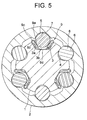
- FIG. 5 is a cross sectional view taken along the line X-X in FIG. 2, showing the telescopic shaft for the vehicle steering according to a second embodiment of the present invention.
- FIG. 6A is a perspective view of the plate spring according to the second embodiment.
- FIG. 6B is a perspective view of the plate spring according to a first modified example of the second embodiment.
- FIG. 6C is a perspective view of the plate spring according to a second modified example of the second embodiment.
- the plate thickness of the spherical member sided contact portion 9a abutting on the spherical member 7 is set thicker than a plate thickness of a portion extending from the groove surface sided contact portion 9b to the biasing portion 9c.
- the preload balance described above is taken in a way that differentiates the rigidities of the spherical member sided contact portions 9a and the groove surface sided contact portions 9b of the plate spring 9 from each other by giving a difference in the plate thicknesses between these two portions 9a and 9b.
- the surface hardness may be, even when uniform on the whole, partially changed as in the first embodiment.
- the plate springs 9 are capable of ensuring the sufficient amount of flexure, with the excessive load (stress) being applied to neither the spherical members 7 nor the plate springs 9, and, when transferring the torque, the stress occurred at the contact portion between the spherical members 7 and the plate springs 9 can be reduced. With this contrivance, the high stress does not occur, and the preload performance can be maintained over a long period of time by preventing the [permanent strain] due to the permanent deformation.
- the portions exhibiting the spring property are set easy to get flexural, thus making it compatible for the single member to have the race surface and the spring property.
- the permanent strain of the plate spring 9 is prevented by hindering the occurrence of the excessive stress on the plate spring 9, thereby enabling the desired preload performance to be maintained over the long period of time.
- the dimensional accuracy is not required to be strictly managed, and the plate spring 9 and the race portion can be made from the single material, thereby making it feasible to reduce the manufacturing cost in a way that facilitates the assembling.
- FIG. 6B is a perspective view of the plate spring according to a first modified example of the second embodiment.
- the curled portions as the biasing portions 9c of the plate spring 9 each is formed with a plurality of holes 21, aligned in the axis-direction, for decreasing the biasing force, thus making it easy for the plate spring 9 to become flexural.
- none of the excessive stress is applied to the contact point with the spherical member 7.
- the biasing portions 9c (the curled portions) are set easy to become flexural, so that the excessive stress is not applied to the contact points with the spherical members 7.
- the surface hardness may be, even when uniform on the whole, partially changed as in the first embodiment.
- FIG. 6C is a perspective view of the plate spring according to a second modified example of the second embodiment.
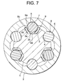
- FIG. 7 is a cross sectional view taken along the line X-X in FIG. 2, showing the telescopic shaft for the vehicle steering according to a third embodiment of the present invention.
- FIG. 8A is a perspective view of the plate spring according to the third embodiment.
- FIG. 8B is a perspective view of the plate spring according to a first modified example of the third embodiment.
- FIG. 8C is a perspective view of the plate spring according to a second modified example of the third embodiment.
- the spherical member sided contact portions 9a abutting on the spherical member 7 each is formed substantially in the circular arc shape.
- the contact surface pressure can be made lower than in the plane shape.
- the spherical member sided contact portions 9a abutting on the spherical member 7 each is formed substantially in the circular arc shape and is therefore set higher than the groove surface sided contact portion 9b taking substantially the plane shape. Note that the surface hardness may be, even when uniform on the whole, partially changed as in the first embodiment.
- the plate spring 9 is capable of ensuring the sufficient amount of flexure, with the excessive load (stress) being applied to neither the spherical member 7 nor the plate spring 9, and, when transferring the torque, the stress occurred at the contact portions between the spherical member 7 and the plate spring 9 can be reduced. With this contrivance, the high stress does not occur, and the preload performance can be maintained over a long period of time by preventing the [permanent strain] due to the permanent deformation.
- the contact points with the spherical member 7, the portions exhibiting the spring property firmly are set easy to get flexural, thus making it compatible for the single member to have the race surface and the spring property.
- the permanent strain of the plate spring 9 is prevented by hindering the occurrence of the excessive stress on the plate spring 9, thereby enabling the desired preload performance to be maintained over the long period of time.
- the dimensional accuracy is not required to be strictly managed, and the plate spring 9 and the race portion can be made from the single material, thereby making it feasible to reduce the manufacturing cost in a way that facilitates the assembling.
- FIG. 8B is a perspective view of the plate spring according to a first modified example of the third embodiment.
- the curled portion as the biasing portion 9c of the plate spring 9 is formed with a plurality of holes 21, aligned in the axis-direction, for decreasing the biasing force, thus making it easy for the plate spring 9 to become flexural.
- the biasing portion 9c (the curled portion) is set easy to become flexural, so that the excessive stress is not applied to the contact point with the spherical member 7.
- the surface hardness may be, even when uniform on the whole, partially changed as in the first embodiment.
- FIG. 8C is a perspective view of the plate spring according to a second modified example of the third embodiment.
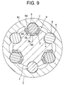
- FIG. 9 is a cross sectional view taken along the line X-X in FIG. 2, showing the telescopic shaft for the vehicle steering according to a fourth embodiment of the present invention.
- FIG. 10A is a perspective view of the plate spring according to the fourth embodiment.
- FIG. 10B is a perspective view of the plate spring according to a first modified example of the fourth embodiment.
- FIG. 10C is a perspective view of the plate spring according to a second modified example of the fourth embodiment.
- the plate thickness of the spherical member sided contact portion 9a abutting on the spherical member 7 is set thicker than a plate thickness of a portion extending from the groove surface sided contact portion 9b to the biasing portion 9c, and the surface abutting on the spherical member 7 is formed substantially in the circular arc shape.
- the contact surface pressure with the spherical member 7 can be made lower than in the plane shape. Note that the surface hardness may be, even when uniform on the whole, partially changed as in the first embodiment.
- the plate spring 9 is capable of ensuring the sufficient amount of flexure, with the excessive load (stress) being applied to neither the spherical member 7 nor the plate spring 9, and, when transferring the torque, the stress occurred at the contact portion between the spherical member 7 and the plate spring 9 can be reduced. With this contrivance, the high stress does not occur, and the preload performance can be maintained over a long period of time by preventing the [permanent strain] due to the permanent deformation.
- the contact points with the spherical member 7, that is, the portions exhibiting the spring property firmly are set easy to get flexural, thus making it compatible for the single member to have the race surface and the spring property.
- the permanent strain of the plate spring 9 is prevented by hindering the occurrence of the excessive stress on the plate spring 9, thereby enabling the desired preload performance to be maintained over the long period of time.
- the dimensional accuracy is not required to be strictly managed, and the plate spring 9 and the race portion can be made from the single material, thereby making it feasible to reduce the manufacturing cost in a way that facilitates the assembling.
- FIG. 10B is a perspective view of the plate spring according to a first modified example of the fourth embodiment.
- the curled portions as the biasing portions 9c of the plate spring 9 each is formed with a plurality of holes 21, aligned in the axis-direction, for decreasing the biasing force, thus making it easy for the plate springs 9 to become flexural.
- none of the excessive stress is applied to the contact points with the spherical member 7.
- the spherical members 7 relatively move in the rotating direction, however, at this time, the biasing portions 9c are set easy to become flexural, so that the excessive stress is not applied to the contact point with the spherical member 7.
- the surface hardness may be, even when uniform on the whole, partially changed as in the first embodiment.
- FIG. 10C is a perspective view of the plate spring according to a second modified example of the fourth embodiment.
- the elastic members each is provided with the space between the transferring member sided contact portion abutting on the first torque transferring member and the groove surface sided contact portion abutting on the axis-directional groove, and the elastic connection is established therebetween.
- the elastic member is capable of ensuring the sufficient amount of flexure, and the excessive load (stress) is applied to neither the first torque transferring member nor the elastic member, and hence, when transferring the torque, it is feasible to decrease the stress occurred at the contact point between the first torque transferring member and the elastic member, whereby the preload performance can be maintained over the long period of time by preventing the [permanent strain] due to the permanent deformation without causing the high stress without causing high stress.
- the contact point with the spherical member 7, the portion exhibiting the spring property firmly is set easy to get flexural, thus making it compatible for the single member to have the race surface and the spring property.
- the structure in the fourth embodiment is that the second torque transferring member mainly transfers the torque, and therefore a further excessive stress is not occurred among the male shaft, the female shaft, the elastic members and the first torque transferring members.
- the permanent strain of the elastic member is prevented by hindering the occurrence of the excessive stress on the elastic members, thereby enabling the desired preload performance to be maintained over the long period of time.
- the dimensional accuracy is not required to be strictly managed, and the elastic members and the race portions can be made from the single material, thereby making it feasible to reduce the manufacturing cost in a way that facilitates the assembling.
Landscapes
- Engineering & Computer Science (AREA)
- General Engineering & Computer Science (AREA)
- Mechanical Engineering (AREA)
- Ocean & Marine Engineering (AREA)
- Chemical & Material Sciences (AREA)
- Combustion & Propulsion (AREA)
- Transportation (AREA)
- Steering Controls (AREA)
- Power Steering Mechanism (AREA)
- Support Of The Bearing (AREA)
- Springs (AREA)
- Bearings For Parts Moving Linearly (AREA)
Applications Claiming Priority (2)
| Application Number | Priority Date | Filing Date | Title |
|---|---|---|---|
| JP2003190514 | 2003-07-02 | ||
| PCT/JP2004/008583 WO2005002947A1 (fr) | 2003-07-02 | 2004-06-11 | Arbre telescopique destine a la direction d'un vehicule a moteur |
Publications (2)
| Publication Number | Publication Date |
|---|---|
| EP1652748A1 true EP1652748A1 (fr) | 2006-05-03 |
| EP1652748A4 EP1652748A4 (fr) | 2007-07-18 |
Family
ID=33562335
Family Applications (1)
| Application Number | Title | Priority Date | Filing Date |
|---|---|---|---|
| EP04746089A Withdrawn EP1652748A4 (fr) | 2003-07-02 | 2004-06-11 | Arbre telescopique destine a la direction d'un vehicule a moteur |
Country Status (5)
| Country | Link |
|---|---|
| US (1) | US7404768B2 (fr) |
| EP (1) | EP1652748A4 (fr) |
| JP (1) | JPWO2005002947A1 (fr) |
| CN (1) | CN100436226C (fr) |
| WO (1) | WO2005002947A1 (fr) |
Cited By (3)
| Publication number | Priority date | Publication date | Assignee | Title |
|---|---|---|---|---|
| DE102007002380B3 (de) * | 2007-01-10 | 2008-06-19 | Thyssenkrupp Presta Ag | Längenveränderbare Lenkspindel |
| EP1972681A4 (fr) * | 2005-12-13 | 2011-04-06 | Nsk Ltd | Arbre d'expansion utilisant un arbre de direction de vehicule et composition lubrifiante de l'arbre d'expansion |
| WO2018154079A1 (fr) * | 2017-02-27 | 2018-08-30 | Thyssenkrupp Presta Ag | Palier lisse pour un arbre de direction et colonne de direction pour un véhicule à moteur |
Families Citing this family (18)
| Publication number | Priority date | Publication date | Assignee | Title |
|---|---|---|---|---|
| CN100390000C (zh) * | 2001-10-01 | 2008-05-28 | 日本精工株式会社 | 车辆转向用伸缩轴 |
| DE60322896D1 (de) * | 2002-06-11 | 2008-09-25 | Nsk Ltd | Teleskopspindel zum lenken eines fahrzeugs und telllenkupplung |
| JP4196630B2 (ja) * | 2002-10-02 | 2008-12-17 | 日本精工株式会社 | 車両ステアリング用伸縮軸 |
| JP4419841B2 (ja) | 2002-11-29 | 2010-02-24 | 日本精工株式会社 | 車両ステアリング用伸縮軸 |
| JP4190905B2 (ja) * | 2003-02-06 | 2008-12-03 | 日本精工株式会社 | 車両用ステアリング装置 |
| US7404768B2 (en) | 2003-07-02 | 2008-07-29 | Nsk Ltd. | Telescopic shaft for motor vehicle steering |
| JP4696916B2 (ja) * | 2004-01-27 | 2011-06-08 | 日本精工株式会社 | 車両ステアリング用伸縮軸 |
| JP2005344747A (ja) * | 2004-05-31 | 2005-12-15 | Koyo Seiko Co Ltd | 動力伝達シャフト |
| JP4770193B2 (ja) * | 2005-02-16 | 2011-09-14 | 日本精工株式会社 | 車両ステアリング用伸縮軸 |
| JP4921762B2 (ja) * | 2005-09-30 | 2012-04-25 | 株式会社ジェイテクト | 伸縮自在シャフトおよび車両操舵用伸縮自在シャフト |
| TWI439709B (zh) * | 2006-12-29 | 2014-06-01 | Intest Corp | 用於使負載沿平移軸線平移之操縱器與負載定位系統 |
| JP2009029301A (ja) * | 2007-07-27 | 2009-02-12 | Jtekt Corp | 車両操舵用伸縮軸およびこれを備える車両用操舵装置 |
| JP5170520B2 (ja) * | 2007-08-31 | 2013-03-27 | 株式会社ジェイテクト | 誤組付防止具およびこれを含む自在継手 |
| CN102066792A (zh) * | 2008-06-20 | 2011-05-18 | 采埃孚转向机系统纳凯姆联合股份公司 | 用于两个滑动轴的带有铰链连接的球联接装置 |
| JP5304524B2 (ja) * | 2009-08-07 | 2013-10-02 | 株式会社ジェイテクト | 内輪と外輪および玉軸受 |
| GB201420942D0 (en) * | 2014-11-25 | 2015-01-07 | Trw Ltd | Improvements to steering column assemblies |
| FR3088889B1 (fr) * | 2018-11-23 | 2020-11-27 | Robert Bosch Automotive Steering Vendome | Dispositif d’accouplement entre deux arbres coaxiaux, notamment pour une colonne de direction de véhicule automobile |
| CN110877634A (zh) * | 2019-12-23 | 2020-03-13 | 天津市精一紧固件有限公司 | 一种机动车转向轴 |
Citations (4)
| Publication number | Priority date | Publication date | Assignee | Title |
|---|---|---|---|---|
| EP0281723A2 (fr) * | 1987-03-12 | 1988-09-14 | FFV Autotech Aktiebolag | Axe téléscopique de transmission de couple avec protection contre surcharge |
| DE3730393A1 (de) * | 1987-09-10 | 1989-03-23 | Lemfoerder Metallwaren Ag | Drehmomentuebertragende verbindung fuer axial ineinander verschiebliche wellenteile, insbesondere der lenkwelle von kraftfahrzeugen |
| WO2004033270A1 (fr) * | 2002-10-10 | 2004-04-22 | Nsk Ltd. | Colonne de direction extensible pour vehicule |
| EP1588921A1 (fr) * | 2003-01-10 | 2005-10-26 | NSK Ltd. | Arbre telescopique pour direction de vehicule a moteur |
Family Cites Families (77)
| Publication number | Priority date | Publication date | Assignee | Title |
|---|---|---|---|---|
| US2607257A (en) * | 1950-08-30 | 1952-08-19 | Minshall Estey Organ Inc | Organ key loading device |
| US3169407A (en) * | 1962-02-28 | 1965-02-16 | Westinghouse Air Brake Co | Motion converting device |
| JPS4519207Y1 (fr) | 1965-01-02 | 1970-08-05 | ||
| US3356424A (en) * | 1965-04-30 | 1967-12-05 | Gen Motors Corp | Ball spline assembly |
| US3392599A (en) * | 1966-12-30 | 1968-07-16 | Gen Motors Corp | Energy absorbing device |
| US3444753A (en) * | 1967-12-14 | 1969-05-20 | Bendix Corp | No-lash axially movable steering column |
| US3604285A (en) * | 1970-04-06 | 1971-09-14 | Saab Scania Ab | Energy-absorbing device and method of making the same |
| CH553350A (fr) * | 1972-06-20 | 1974-08-30 | Betrix Claude | Dispositif de guidage du deplacement axial d'un organe cylindrique. |
| DE2461289B1 (de) * | 1974-12-23 | 1975-11-13 | Loehr & Bromkamp Gmbh | Gleichlaufdrehgelenk |
| DE2804778C3 (de) * | 1978-02-04 | 1982-04-08 | Uni-Cardan Ag, 5200 Siegburg | Teleskopantriebswelle |
| US4384861A (en) * | 1979-10-10 | 1983-05-24 | Firma LWM Lemforder Gelenkwellen GmbH | Universal joint shaft, particularly for a steering column of motor vehicles |
| US4357137A (en) * | 1980-08-18 | 1982-11-02 | Arinc Research Corporation | Shaft coupling |
| US4500141A (en) * | 1982-09-13 | 1985-02-19 | Daugherty Estes M | Drill steel idler guide |
| US4509386A (en) * | 1982-11-15 | 1985-04-09 | General Motors Corporation | Lash-free telescopic steering shaft assembly and method of making the assembly |
| SE450153B (sv) * | 1985-01-22 | 1987-06-09 | Ffv Affersverket | Teleskopstyrning, speciellt for overforing av vridmoment |
| AT384405B (de) * | 1985-07-22 | 1987-11-10 | Supervis Ets | Laengenveraenderbare lenkspindel fuer lenkvorrichtungen bei kraftfahrzeugen |
| JPS62244758A (ja) | 1986-04-18 | 1987-10-26 | Koyo Seiko Co Ltd | ステアリングハンドルの位置調整装置 |
| JPH01145670A (ja) | 1987-12-01 | 1989-06-07 | Minolta Camera Co Ltd | 複合化装置 |
| US5184978A (en) * | 1990-04-16 | 1993-02-09 | Gkn Automotive, Inc. | Telescopic triplan universal joint |
| JPH0443522U (fr) | 1990-08-16 | 1992-04-14 | ||
| JPH04123775A (ja) | 1990-09-14 | 1992-04-23 | Sony Corp | コネクター装置 |
| JP2916708B2 (ja) | 1990-10-26 | 1999-07-05 | 本田技研工業株式会社 | 移動体の現在位置測定装置 |
| FR2669693A1 (fr) * | 1990-11-23 | 1992-05-29 | Nacam | Accouplement extensible perfectionne pour solidariser en rotation deux arbres avec systeme de securite integre et son application notamment aux directions d'automobiles. |
| JP2538390Y2 (ja) * | 1991-04-22 | 1997-06-11 | 富士機工株式会社 | 伸縮自在シャフト |
| US5235734A (en) * | 1991-11-04 | 1993-08-17 | Itt Corporation | Collapsible steering shaft apparatus and method of making same |
| US5460574A (en) * | 1993-08-31 | 1995-10-24 | Trw Inc. | Variable length shaft assembly with a lash bushing |
| US5542343A (en) * | 1995-09-26 | 1996-08-06 | Trw Inc. | Power steering assembly with damping ring |
| DE19538303A1 (de) | 1995-10-14 | 1997-04-17 | Zahnradfabrik Friedrichshafen | Lenksäule eines Kraftfahrzeuges |
| JP3671571B2 (ja) * | 1996-02-29 | 2005-07-13 | 株式会社デンソー | 動力伝達装置 |
| US5709605A (en) * | 1996-12-23 | 1998-01-20 | General Motors Corporation | Shaft coupling |
| FR2759436B1 (fr) * | 1997-02-11 | 1999-04-30 | Pierre Guimbretiere | Joint homocinetique coulissant a tripode |
| DE19801166C2 (de) * | 1998-01-15 | 2001-06-28 | Micro Compact Car Smart Gmbh | Kraftfahrzeug-Lenkwelle mit zwei Wellenabschnitten |
| DE19820291B4 (de) | 1998-05-07 | 2006-06-14 | Willi Elbe Gelenkwellen Gmbh & Co. Kg | Mehrfach teleskopierbare Lenkwelle mit Blockiereinrichtung |
| DE19824477A1 (de) | 1998-05-30 | 1999-12-02 | Daimler Chrysler Ag | Teleskopische Lenkwelle für Kraftfahrzeuge |
| JP3659033B2 (ja) | 1998-11-24 | 2005-06-15 | 日本精工株式会社 | 衝撃吸収式電動パワーステアリング装置 |
| JP2000205288A (ja) | 1999-01-12 | 2000-07-25 | Koyo Seiko Co Ltd | ドライブシャフト |
| DE19905350A1 (de) | 1999-02-10 | 2000-08-24 | Daimler Chrysler Ag | Kombiniertes Schiebestück mit Schwingungsentkopplung |
| ES2161127B1 (es) * | 1999-03-16 | 2002-09-01 | Castellon Melchor Daumal | Arbol telescopico para columnas de direccion en vehiculos de automoviles con sistema de deslizamiento con control de carga. |
| JP2000337395A (ja) | 1999-05-27 | 2000-12-05 | Koyo Seiko Co Ltd | ボールスプライン機構付き推進軸 |
| FR2795787B1 (fr) | 1999-06-30 | 2003-05-23 | Nacam | Dispositif d'accouplement a billes de deux arbres coulissants |
| FR2795785B1 (fr) * | 1999-06-30 | 2002-06-28 | Nacam | Dispositif d'accouplement a billes de deux arbres coulissants |
| EP1106851B1 (fr) | 1999-12-10 | 2001-08-01 | SKF LINEARSYSTEME GmbH | Palier à roulement pour mouvements longitudinaux |
| US6279953B1 (en) * | 1999-12-22 | 2001-08-28 | Trw Inc. | Flexible mount for an intermediate steering column |
| JP2001239944A (ja) * | 2000-03-01 | 2001-09-04 | Nsk Ltd | 伸縮自在シャフトの結合構造 |
| US6364778B1 (en) | 2000-05-25 | 2002-04-02 | Spicer Driveshaft, Inc. | Axially adjustable steering shaft assembly with ball spline |
| JP3694637B2 (ja) * | 2000-06-27 | 2005-09-14 | 光洋精工株式会社 | ボールスプライン継手及びステアリング装置の中間軸 |
| FR2811041B1 (fr) | 2000-06-28 | 2002-10-11 | Nadella | Module de coulisse a billes et ensemble correspondant |
| JP2002046633A (ja) | 2000-08-07 | 2002-02-12 | Nsk Ltd | 電動パワーステアリング装置 |
| US6582313B2 (en) * | 2000-12-22 | 2003-06-24 | Delphi Technologies, Inc. | Constant velocity stroking joint having recirculating spline balls |
| US6505969B2 (en) | 2001-01-31 | 2003-01-14 | The Torrington Company | Interlocking linear roller bearing |
| US6533459B2 (en) * | 2001-01-31 | 2003-03-18 | The Torrington Company | Adjustable, self-aligning, linear roller bearing |
| DE10106982A1 (de) * | 2001-02-15 | 2002-08-29 | Ina Schaeffler Kg | Linearführung |
| US6533666B2 (en) | 2001-04-03 | 2003-03-18 | Delphi Technologies, Inc. | Intermediate steering shaft for motor vehicle |
| DE10123413B4 (de) * | 2001-05-14 | 2006-03-16 | Gkn Driveline Deutschland Gmbh | Antriebswelle |
| JP4571341B2 (ja) * | 2001-06-18 | 2010-10-27 | 水島プレス工業株式会社 | ステアリング装置のダンパ機構 |
| CN100390000C (zh) * | 2001-10-01 | 2008-05-28 | 日本精工株式会社 | 车辆转向用伸缩轴 |
| FR2830912B1 (fr) * | 2001-10-15 | 2003-12-19 | Nacam | Dispositif d'accouplement en rotation de deux arbres telescopiques |
| US6620050B2 (en) * | 2001-10-30 | 2003-09-16 | Mando Corporation | Universal joint |
| US7226360B2 (en) * | 2001-12-14 | 2007-06-05 | Gkn Driveline North America, Inc. | Grease cap for a constant velocity joint |
| US6761503B2 (en) * | 2002-04-24 | 2004-07-13 | Torque-Traction Technologies, Inc. | Splined member for use in a slip joint and method of manufacturing the same |
| US6729648B2 (en) * | 2002-06-07 | 2004-05-04 | Sealy Technology Llc | Non-linear energy absorbing column assembly |
| DE60322896D1 (de) * | 2002-06-11 | 2008-09-25 | Nsk Ltd | Teleskopspindel zum lenken eines fahrzeugs und telllenkupplung |
| DE50302563D1 (de) * | 2002-06-18 | 2006-05-04 | Dura Automotive Systems Reiche | Lenkwelle für Kraftfahrzeuge |
| US6893353B2 (en) * | 2002-06-18 | 2005-05-17 | Torque-Traction Technologies, Inc. | Rolling ball spline slip joint formed from two tubular members |
| DE20212294U1 (de) | 2002-06-18 | 2003-10-30 | Dura Automotive Systems Reiche | Lenkwelle für Kraftfahrzeuge |
| DE10233758B4 (de) * | 2002-07-25 | 2004-07-29 | Gkn Driveline Deutschland Gmbh | Längsverschiebeeinheit mit Bremsrollen |
| JP3797304B2 (ja) * | 2002-09-13 | 2006-07-19 | 日本精工株式会社 | 車両ステアリング用伸縮軸 |
| JP4196630B2 (ja) | 2002-10-02 | 2008-12-17 | 日本精工株式会社 | 車両ステアリング用伸縮軸 |
| JP4196642B2 (ja) * | 2002-10-24 | 2008-12-17 | 日本精工株式会社 | 車両ステアリング用伸縮軸 |
| JP4419841B2 (ja) * | 2002-11-29 | 2010-02-24 | 日本精工株式会社 | 車両ステアリング用伸縮軸 |
| JP2004196261A (ja) * | 2002-12-20 | 2004-07-15 | Nsk Ltd | 車両ステアリング用伸縮軸 |
| JP4190905B2 (ja) * | 2003-02-06 | 2008-12-03 | 日本精工株式会社 | 車両用ステアリング装置 |
| US7404768B2 (en) | 2003-07-02 | 2008-07-29 | Nsk Ltd. | Telescopic shaft for motor vehicle steering |
| US20050070365A1 (en) * | 2003-09-30 | 2005-03-31 | Riefe Richard K. | Bushing for telescoping steering column assembly |
| JP4696916B2 (ja) * | 2004-01-27 | 2011-06-08 | 日本精工株式会社 | 車両ステアリング用伸縮軸 |
| FR2875279B1 (fr) * | 2004-09-14 | 2006-11-24 | Nacam France Sas | Dispositif d'accouplement a billes a maintien articule de deux arbres coulissants |
| JP4770193B2 (ja) * | 2005-02-16 | 2011-09-14 | 日本精工株式会社 | 車両ステアリング用伸縮軸 |
-
2004
- 2004-06-11 US US10/563,324 patent/US7404768B2/en active Active
- 2004-06-11 EP EP04746089A patent/EP1652748A4/fr not_active Withdrawn
- 2004-06-11 WO PCT/JP2004/008583 patent/WO2005002947A1/fr active Application Filing
- 2004-06-11 JP JP2005511316A patent/JPWO2005002947A1/ja active Pending
- 2004-06-11 CN CNB2004800225601A patent/CN100436226C/zh not_active Expired - Fee Related
Patent Citations (4)
| Publication number | Priority date | Publication date | Assignee | Title |
|---|---|---|---|---|
| EP0281723A2 (fr) * | 1987-03-12 | 1988-09-14 | FFV Autotech Aktiebolag | Axe téléscopique de transmission de couple avec protection contre surcharge |
| DE3730393A1 (de) * | 1987-09-10 | 1989-03-23 | Lemfoerder Metallwaren Ag | Drehmomentuebertragende verbindung fuer axial ineinander verschiebliche wellenteile, insbesondere der lenkwelle von kraftfahrzeugen |
| WO2004033270A1 (fr) * | 2002-10-10 | 2004-04-22 | Nsk Ltd. | Colonne de direction extensible pour vehicule |
| EP1588921A1 (fr) * | 2003-01-10 | 2005-10-26 | NSK Ltd. | Arbre telescopique pour direction de vehicule a moteur |
Non-Patent Citations (1)
| Title |
|---|
| See also references of WO2005002947A1 * |
Cited By (6)
| Publication number | Priority date | Publication date | Assignee | Title |
|---|---|---|---|---|
| EP1972681A4 (fr) * | 2005-12-13 | 2011-04-06 | Nsk Ltd | Arbre d'expansion utilisant un arbre de direction de vehicule et composition lubrifiante de l'arbre d'expansion |
| DE102007002380B3 (de) * | 2007-01-10 | 2008-06-19 | Thyssenkrupp Presta Ag | Längenveränderbare Lenkspindel |
| WO2008083829A1 (fr) | 2007-01-10 | 2008-07-17 | Thyssenkrupp Presta Aktiengesellschaft | Arbre de direction de longueur variable |
| US8435124B2 (en) | 2007-01-10 | 2013-05-07 | Thyssenkrupp Presta Aktiengesellschaft | Variable length steering spindle |
| WO2018154079A1 (fr) * | 2017-02-27 | 2018-08-30 | Thyssenkrupp Presta Ag | Palier lisse pour un arbre de direction et colonne de direction pour un véhicule à moteur |
| US11473617B2 (en) | 2017-02-27 | 2022-10-18 | Thyssenkrupp Presta Ag | Sliding bearing for a steering spindle and steering column for a motor vehicle |
Also Published As
| Publication number | Publication date |
|---|---|
| CN1832880A (zh) | 2006-09-13 |
| US7404768B2 (en) | 2008-07-29 |
| WO2005002947A1 (fr) | 2005-01-13 |
| CN100436226C (zh) | 2008-11-26 |
| EP1652748A4 (fr) | 2007-07-18 |
| US20060252559A1 (en) | 2006-11-09 |
| JPWO2005002947A1 (ja) | 2006-08-10 |
Similar Documents
| Publication | Publication Date | Title |
|---|---|---|
| US7404768B2 (en) | Telescopic shaft for motor vehicle steering | |
| US7416216B2 (en) | Telescopic shaft for vehicle steering | |
| EP1512607B1 (fr) | Arbre telescopique permettant de diriger un vehicule et arbre telescopique permettant de diriger un vehicule au moyen d'un accouplement d'arbre a cardan | |
| JP4770193B2 (ja) | 車両ステアリング用伸縮軸 | |
| US7416199B2 (en) | Steering device for motor vehicle | |
| US7559267B2 (en) | Extendable shaft for vehicle steering | |
| US7481130B2 (en) | Vehicle steering telescopic shaft | |
| US20060156855A1 (en) | Telescopic shaft for motor vehicle steering | |
| EP1553005B1 (fr) | Colonne de direction extensible pour vehicule | |
| EP1584538A1 (fr) | Arbre telescopique pour direction de vehicule automobile | |
| JP4586983B2 (ja) | 車両ステアリング用伸縮軸 | |
| WO2005102820A1 (fr) | Colonne démontable pour direction du véhicule | |
| JP2007321789A (ja) | 機械部品の組立方法 | |
| JP2005262919A (ja) | 車両ステアリング用伸縮軸 | |
| JP2007191149A (ja) | 車両ステアリング用伸縮軸、及びカルダン軸継手付き車両ステアリング用伸縮軸 | |
| JP2003063414A (ja) | 車両ステアリング用伸縮軸 |
Legal Events
| Date | Code | Title | Description |
|---|---|---|---|
| PUAI | Public reference made under article 153(3) epc to a published international application that has entered the european phase |
Free format text: ORIGINAL CODE: 0009012 |
|
| 17P | Request for examination filed |
Effective date: 20060131 |
|
| AK | Designated contracting states |
Kind code of ref document: A1 Designated state(s): DE GB |
|
| DAX | Request for extension of the european patent (deleted) | ||
| RBV | Designated contracting states (corrected) |
Designated state(s): DE GB |
|
| A4 | Supplementary search report drawn up and despatched |
Effective date: 20070618 |
|
| 17Q | First examination report despatched |
Effective date: 20071112 |
|
| STAA | Information on the status of an ep patent application or granted ep patent |
Free format text: STATUS: THE APPLICATION IS DEEMED TO BE WITHDRAWN |
|
| 18D | Application deemed to be withdrawn |
Effective date: 20110104 |