EP1588921A1 - Arbre telescopique pour direction de vehicule a moteur - Google Patents
Arbre telescopique pour direction de vehicule a moteur Download PDFInfo
- Publication number
- EP1588921A1 EP1588921A1 EP04700759A EP04700759A EP1588921A1 EP 1588921 A1 EP1588921 A1 EP 1588921A1 EP 04700759 A EP04700759 A EP 04700759A EP 04700759 A EP04700759 A EP 04700759A EP 1588921 A1 EP1588921 A1 EP 1588921A1
- Authority
- EP
- European Patent Office
- Prior art keywords
- shaft
- contact portion
- contact
- vehicle steering
- male
- Prior art date
- Legal status (The legal status is an assumption and is not a legal conclusion. Google has not performed a legal analysis and makes no representation as to the accuracy of the status listed.)
- Withdrawn
Links
- 230000002093 peripheral effect Effects 0.000 claims abstract description 19
- 239000000463 material Substances 0.000 claims description 21
- 229920003002 synthetic resin Polymers 0.000 claims description 8
- 239000000057 synthetic resin Substances 0.000 claims description 8
- 238000005096 rolling process Methods 0.000 claims description 5
- 239000000314 lubricant Substances 0.000 claims description 4
- 230000005540 biological transmission Effects 0.000 description 33
- 230000036316 preload Effects 0.000 description 23
- 230000007774 longterm Effects 0.000 description 7
- 230000033001 locomotion Effects 0.000 description 6
- 230000007246 mechanism Effects 0.000 description 6
- 238000006073 displacement reaction Methods 0.000 description 4
- 238000004519 manufacturing process Methods 0.000 description 4
- 102100030393 G-patch domain and KOW motifs-containing protein Human genes 0.000 description 3
- 238000005299 abrasion Methods 0.000 description 3
- 230000008878 coupling Effects 0.000 description 3
- 238000010168 coupling process Methods 0.000 description 3
- 238000005859 coupling reaction Methods 0.000 description 3
- 239000004519 grease Substances 0.000 description 3
- 230000001050 lubricating effect Effects 0.000 description 3
- 229910052982 molybdenum disulfide Inorganic materials 0.000 description 3
- 229920006284 nylon film Polymers 0.000 description 3
- 239000004810 polytetrafluoroethylene Substances 0.000 description 3
- 229920001343 polytetrafluoroethylene Polymers 0.000 description 3
- 238000012545 processing Methods 0.000 description 3
- 239000007787 solid Substances 0.000 description 3
- OKTJSMMVPCPJKN-UHFFFAOYSA-N Carbon Chemical compound [C] OKTJSMMVPCPJKN-UHFFFAOYSA-N 0.000 description 2
- 229910000831 Steel Inorganic materials 0.000 description 2
- 229910052799 carbon Inorganic materials 0.000 description 2
- 230000008859 change Effects 0.000 description 2
- 238000013461 design Methods 0.000 description 2
- 230000006866 deterioration Effects 0.000 description 2
- 230000000694 effects Effects 0.000 description 2
- 239000013013 elastic material Substances 0.000 description 2
- 239000011572 manganese Substances 0.000 description 2
- 238000000034 method Methods 0.000 description 2
- 238000003825 pressing Methods 0.000 description 2
- 239000010959 steel Substances 0.000 description 2
- 238000004381 surface treatment Methods 0.000 description 2
- 238000007669 thermal treatment Methods 0.000 description 2
- PWHULOQIROXLJO-UHFFFAOYSA-N Manganese Chemical compound [Mn] PWHULOQIROXLJO-UHFFFAOYSA-N 0.000 description 1
- 230000002457 bidirectional effect Effects 0.000 description 1
- 239000000919 ceramic Substances 0.000 description 1
- 238000006243 chemical reaction Methods 0.000 description 1
- 230000006835 compression Effects 0.000 description 1
- 238000007906 compression Methods 0.000 description 1
- 239000000470 constituent Substances 0.000 description 1
- 230000003247 decreasing effect Effects 0.000 description 1
- 230000005489 elastic deformation Effects 0.000 description 1
- 238000011156 evaluation Methods 0.000 description 1
- 229910052748 manganese Inorganic materials 0.000 description 1
- 230000008569 process Effects 0.000 description 1
- 230000002035 prolonged effect Effects 0.000 description 1
- 230000000644 propagated effect Effects 0.000 description 1
- 238000010791 quenching Methods 0.000 description 1
- 230000000171 quenching effect Effects 0.000 description 1
- 230000004044 response Effects 0.000 description 1
- 230000000717 retained effect Effects 0.000 description 1
- 230000002441 reversible effect Effects 0.000 description 1
- 102220005308 rs33960931 Human genes 0.000 description 1
- 230000001953 sensory effect Effects 0.000 description 1
- 238000000926 separation method Methods 0.000 description 1
- 230000003746 surface roughness Effects 0.000 description 1
- 238000005496 tempering Methods 0.000 description 1
- 238000012360 testing method Methods 0.000 description 1
Images


Classifications
-
- F—MECHANICAL ENGINEERING; LIGHTING; HEATING; WEAPONS; BLASTING
- F16—ENGINEERING ELEMENTS AND UNITS; GENERAL MEASURES FOR PRODUCING AND MAINTAINING EFFECTIVE FUNCTIONING OF MACHINES OR INSTALLATIONS; THERMAL INSULATION IN GENERAL
- F16C—SHAFTS; FLEXIBLE SHAFTS; ELEMENTS OR CRANKSHAFT MECHANISMS; ROTARY BODIES OTHER THAN GEARING ELEMENTS; BEARINGS
- F16C29/00—Bearings for parts moving only linearly
- F16C29/002—Elastic or yielding linear bearings or bearing supports
-
- B—PERFORMING OPERATIONS; TRANSPORTING
- B62—LAND VEHICLES FOR TRAVELLING OTHERWISE THAN ON RAILS
- B62D—MOTOR VEHICLES; TRAILERS
- B62D1/00—Steering controls, i.e. means for initiating a change of direction of the vehicle
- B62D1/02—Steering controls, i.e. means for initiating a change of direction of the vehicle vehicle-mounted
- B62D1/16—Steering columns
- B62D1/18—Steering columns yieldable or adjustable, e.g. tiltable
- B62D1/185—Steering columns yieldable or adjustable, e.g. tiltable adjustable by axial displacement, e.g. telescopically
-
- B—PERFORMING OPERATIONS; TRANSPORTING
- B62—LAND VEHICLES FOR TRAVELLING OTHERWISE THAN ON RAILS
- B62D—MOTOR VEHICLES; TRAILERS
- B62D1/00—Steering controls, i.e. means for initiating a change of direction of the vehicle
- B62D1/02—Steering controls, i.e. means for initiating a change of direction of the vehicle vehicle-mounted
- B62D1/16—Steering columns
- B62D1/20—Connecting steering column to steering gear
-
- F—MECHANICAL ENGINEERING; LIGHTING; HEATING; WEAPONS; BLASTING
- F16—ENGINEERING ELEMENTS AND UNITS; GENERAL MEASURES FOR PRODUCING AND MAINTAINING EFFECTIVE FUNCTIONING OF MACHINES OR INSTALLATIONS; THERMAL INSULATION IN GENERAL
- F16C—SHAFTS; FLEXIBLE SHAFTS; ELEMENTS OR CRANKSHAFT MECHANISMS; ROTARY BODIES OTHER THAN GEARING ELEMENTS; BEARINGS
- F16C29/00—Bearings for parts moving only linearly
- F16C29/007—Hybrid linear bearings, i.e. including more than one bearing type, e.g. sliding contact bearings as well as rolling contact bearings
-
- F—MECHANICAL ENGINEERING; LIGHTING; HEATING; WEAPONS; BLASTING
- F16—ENGINEERING ELEMENTS AND UNITS; GENERAL MEASURES FOR PRODUCING AND MAINTAINING EFFECTIVE FUNCTIONING OF MACHINES OR INSTALLATIONS; THERMAL INSULATION IN GENERAL
- F16C—SHAFTS; FLEXIBLE SHAFTS; ELEMENTS OR CRANKSHAFT MECHANISMS; ROTARY BODIES OTHER THAN GEARING ELEMENTS; BEARINGS
- F16C29/00—Bearings for parts moving only linearly
- F16C29/04—Ball or roller bearings
-
- F—MECHANICAL ENGINEERING; LIGHTING; HEATING; WEAPONS; BLASTING
- F16—ENGINEERING ELEMENTS AND UNITS; GENERAL MEASURES FOR PRODUCING AND MAINTAINING EFFECTIVE FUNCTIONING OF MACHINES OR INSTALLATIONS; THERMAL INSULATION IN GENERAL
- F16C—SHAFTS; FLEXIBLE SHAFTS; ELEMENTS OR CRANKSHAFT MECHANISMS; ROTARY BODIES OTHER THAN GEARING ELEMENTS; BEARINGS
- F16C29/00—Bearings for parts moving only linearly
- F16C29/12—Arrangements for adjusting play
- F16C29/123—Arrangements for adjusting play using elastic means
-
- F—MECHANICAL ENGINEERING; LIGHTING; HEATING; WEAPONS; BLASTING
- F16—ENGINEERING ELEMENTS AND UNITS; GENERAL MEASURES FOR PRODUCING AND MAINTAINING EFFECTIVE FUNCTIONING OF MACHINES OR INSTALLATIONS; THERMAL INSULATION IN GENERAL
- F16C—SHAFTS; FLEXIBLE SHAFTS; ELEMENTS OR CRANKSHAFT MECHANISMS; ROTARY BODIES OTHER THAN GEARING ELEMENTS; BEARINGS
- F16C3/00—Shafts; Axles; Cranks; Eccentrics
- F16C3/02—Shafts; Axles
- F16C3/03—Shafts; Axles telescopic
- F16C3/035—Shafts; Axles telescopic with built-in bearings
-
- F—MECHANICAL ENGINEERING; LIGHTING; HEATING; WEAPONS; BLASTING
- F16—ENGINEERING ELEMENTS AND UNITS; GENERAL MEASURES FOR PRODUCING AND MAINTAINING EFFECTIVE FUNCTIONING OF MACHINES OR INSTALLATIONS; THERMAL INSULATION IN GENERAL
- F16C—SHAFTS; FLEXIBLE SHAFTS; ELEMENTS OR CRANKSHAFT MECHANISMS; ROTARY BODIES OTHER THAN GEARING ELEMENTS; BEARINGS
- F16C33/00—Parts of bearings; Special methods for making bearings or parts thereof
- F16C33/30—Parts of ball or roller bearings
- F16C33/58—Raceways; Race rings
- F16C33/62—Selection of substances
-
- F—MECHANICAL ENGINEERING; LIGHTING; HEATING; WEAPONS; BLASTING
- F16—ENGINEERING ELEMENTS AND UNITS; GENERAL MEASURES FOR PRODUCING AND MAINTAINING EFFECTIVE FUNCTIONING OF MACHINES OR INSTALLATIONS; THERMAL INSULATION IN GENERAL
- F16D—COUPLINGS FOR TRANSMITTING ROTATION; CLUTCHES; BRAKES
- F16D3/00—Yielding couplings, i.e. with means permitting movement between the connected parts during the drive
- F16D3/02—Yielding couplings, i.e. with means permitting movement between the connected parts during the drive adapted to specific functions
- F16D3/06—Yielding couplings, i.e. with means permitting movement between the connected parts during the drive adapted to specific functions specially adapted to allow axial displacement
- F16D3/065—Yielding couplings, i.e. with means permitting movement between the connected parts during the drive adapted to specific functions specially adapted to allow axial displacement by means of rolling elements
-
- F—MECHANICAL ENGINEERING; LIGHTING; HEATING; WEAPONS; BLASTING
- F16—ENGINEERING ELEMENTS AND UNITS; GENERAL MEASURES FOR PRODUCING AND MAINTAINING EFFECTIVE FUNCTIONING OF MACHINES OR INSTALLATIONS; THERMAL INSULATION IN GENERAL
- F16C—SHAFTS; FLEXIBLE SHAFTS; ELEMENTS OR CRANKSHAFT MECHANISMS; ROTARY BODIES OTHER THAN GEARING ELEMENTS; BEARINGS
- F16C2326/00—Articles relating to transporting
- F16C2326/20—Land vehicles
- F16C2326/24—Steering systems, e.g. steering rods or columns
Definitions
- the present invention relates to a telescopic shaft for vehicle steering which is installed in a steering shaft of a vehicle and in which a male shaft and a female shaft are fitted to each other to be mutually unrotatable and slidable.
- a telescopic shaft of a steering mechanism of a vehicle is required to have a property of absorbing an axial displacement which is generated when the vehicle is running and of preventing such displacement or vibration from being propagated onto a steering wheel. Further, the telescopic shaft is also required to have a function of moving the position of the steering wheel in the axial direction and then adjusting this position in order to obtain an optimal position for the driver to drive the vehicle.
- the telescopic shaft is required to reduce rattling noise, to decrease backlash feeling on the steering wheel, and to reduce a sliding resistance during a sliding operation in the axial direction.
- a male shaft of the telescopic shaft is coated with nylon film and grease is applied onto a sliding portion thereof, so as to absorb or mitigate metallic noise and metallic rattle and, at the same time, to reduce a sliding resistance and backlash in the direction of rotation.
- leaf springs each serving as an elastic member for applying preload to the male shaft and the female shaft through the spherical members serving as the torque transmitting members are interposed between the inner side or the outer side in the radial direction of the spherical members serving as the torque transmitting members and the axial grooves of each pair.
- the male shaft and the female shaft can transmit the torque in a state of high rigidity by preventing backlash in the direction of rotation thereof.
- one leaf spring for applying preload to one set of torque transmitting members (spherical members) and another leaf spring for applying preload to another set of torque transmitting members (spherical members) which is adjacent to the former leaf spring in the circumferential direction are coupled together in the circumferential direction with a web which is an arch-shaped coupling portion extended in the circumferential direction.
- This coupling portion (web) is provided to give the above-described two leaf springs tension and compression force therebetween, thereby generating preload in the two leaf springs.
- the present invention has been contrived taking such circumstances as described above into consideration, and an object thereof is to provide a telescopic shaft for vehicle steering which is capable of preventing backlash in a direction of rotation without fail, thereby transmitting torque in a state of high rigidity.
- a telescopic shaft for vehicle steering which is installed in a steering shaft of a vehicle and in which a male shaft and a female shaft are fitted to each other to be unrotatable and freely slidable, characterized in that:
- a telescopic shaft for vehicle steering which can securely prevent backlash in the direction of rotation and can transmit torque in a sate of high rigidity.
- the telescopic shaft can achieve a stable sliding load.
- the contact portion on the transmitting member side can be sufficiently flexed through the biasing portion, so that a flexural amount can be sufficiently secured.
- the second transmitting member Since the telescopic shaft is provided with the second torque transmitting member, in addition to the first torque transmitting member, the second transmitting member is brought into contact with the axial grooves of the male shaft and the female shaft before the elastic member at the time of torque transmission, so that the second torque transmitting member can transmit the torque mainly, so that an excessive load (stress) is not applied on the first torque transmitting member and the elastic member.
- the elastic member can secure a sufficient flexural amount, as described above, and at the same time, an excessive load (stress) is not applied on the first torque transmitting member and the elastic member, it is possible to mitigate the stress which is generated in the contact portion between the first transmitting member and the elastic member at the time of torque transmission. With this arrangement, no great stress is not produced, and the "worn-out condition" due to the permanent deformation can be prevented so as to maintain the preload performance for a long term.
- the contact portion on the transmitting member side thereof is in contact with the first torque transmitting member and, at the same time, the contact portion on the groove surface side thereof is in contact with the groove surface of the axial groove, so that the elastic member is in a state that it is fitted to the axial groove to each other.
- the elastic member is in a state that it is fitted to the axial groove to each other.
- the contact portions remain on the same line, irrespective of loaded condition of the torque.
- the contact angle is not changed, whereby the linear torsional property required for the steering shaft can be obtained and the steering property which is linear and has high rigid feeling can be obtained.
- the first torque transmitting member is a rolling member which is rotated when both the shafts are moved relatively to each other in the axial direction
- the second torque transmitting member is a sliding member which slides in a slip manner when both the shafts are moved relatively to each other in the axial direction.
- the first torque transmitting member comprises a rolling member which is rotated when both the shafts are moved relatively to each other in the axial direction
- the second torque transmitting member comprises a sliding member which slides in a slip manner hen both the shafts are moved relatively to each other in the axial direction.
- the biasing portion of the elastic member is in a folded-back form which is folded back between the contact portion on the transmitting member side and the contact portion on the groove surface side.
- the biasing portion of the elastic member is in a folded-back form which is folded back between the contact portion on the transmitting member side and the contact portion on the groove surface side, it is possible to elastically bias the contact portion on the transmitting member side and the contact portion on the groove surface side by the use of this biasing portion in the folded-back form so that these two contact portions are separated from each other.
- the telescopic shaft for vehicle steering such that the axial groove of the male shaft or the female shaft comprises a flat-shaped side surface which is in contact with a contact portion on the groove surface and a bottom surface which is connected to the flat-shaped side surface, the elastic member has a bottom portion opposed to the bottom surface of the axial groove, and the bottom portion of the elastic member is in a state of contacting with the bottom surface of the axial groove, or the bottom surface of the axial groove is separated from the bottom portion of the elastic portion by a predetermined distance.
- the hysteresis can be controlled by bringing the bottom portion of the elastic member into contact with the bottom surface of the axial groove in case of need, so that a desired hysteresis can be obtained. That is, the hysteresis is required to be changed in various manners depending on a matching condition with the steering performance of each vehicle. More specifically, if the bottom portion of the elastic member is set in the state of contacting with the bottom surface of the axial groove, friction is caused when the axial groove and the elastic member are moved relatively to each other, so that the hysteresis can be set as comparatively great.
- the biasing portion of the elastic member may be separately provided from the contact portion on the transmitting member side and the contact portion on the groove surface side, and may be formed of a material different therefrom.
- the elastic member may have, in addition to the contact portion on the transmitting member side, the contact portion on the groove surface side and the biasing portion, a second biasing portion which is formed separately of a material different therefrom.
- the elastic member may be arranged to comprise a leaf spring.
- the elastic member can achieve the steering property with a desired high rigid feeling while suppressing the manufacturing cost.
- the biasing member which is separately formed of a different material and the second biasing member which is also separately formed of a different material may be formed of rubber or synthetic resin.
- a lubricating agent is applied between the axial groove of the male shaft, the axial groove of the female shaft, the elastic member and the first torque transmitting member. According to this structure, since the lubricating agent is applied between the axial groove of the male shaft, the axial groove of the female shaft, the elastic member and the first torque transmitting member, the male shaft and the female shaft can slide in the axial direction with a stable sliding load without backlash at the time of torque transmission.
- a predetermined gap provided among the male shaft, the second torque transmitting member and the female shaft so that it is preferable that the relation of A > B is satisfied when a rotatable angle among the male shaft, the elastic member, the first torque transmitting member and the female shaft in the circumferential direction of the male shaft is A, and an angle of rotation of the among between the male shaft, the second torque transmitting member and the female shaft in the circumferential direction of the male shaft is B.
- the angle of rotation B of the male shaft for the predetermined gap is set within a range from 0.01° to 0.25° .
- a telescopic shaft for vehicle steering according to embodiments of the present invention will be described below with reference to drawings.
- Fig. 1 is a side view of a steering mechanism of a vehicle in which a telescopic shaft for vehicle steering according to an embodiment of the present invention is applied.
- the steering mechanism is constituted by an upper steering shaft portion 120 (including a steering column 103 and a steering shaft 104 retained by the steering column 103 to be rotatable) which is attached to a vehicle body-side member 100 through an upper bracket 101 and a lower bracket 102, a steering wheel 105 which is attached to an upper end of the steering shaft 104, a lower steering shaft portion 107 which is coupled to a lower end of the steering shaft 104 through a universal joint 106, a pinion shaft 109 which is coupled to the lower steering shaft portion 107 through a steering shaft joint 108, a steering rack shaft 112 coupled to the pinion shaft 109, and a steering rack supporting member 113 which supports the steering rack shaft 112 and is fixed to another frame of the vehicle body through an elastic member 111.
- each of the upper steering shaft portion 120 and the lower steering shaft portion 107 employs a telescopic shaft for vehicle steering according to an embodiment of the present invention (hereinafter called the telescopic shaft).
- the lower steering shaft portion 107 is formed by fitting a male shaft and a female shaft to each other.
- Such a lower steering shaft portion 107 is required to have the property of absorbing an axial displacement which is generated during the running of the vehicle so as not to transmit the displacement or vibration onto the steering wheel 105.
- Such a property is required for a structure in which the vehicle body is in a sub-frame structure so that the member 100 for fixing an upper part of the steering mechanism is separately provided from the frame 110 to which the steering rack supporting member 113 is fixed, and the steering rack supporting member 113 is fixedly clamped to the frame 110 through the elastic member 111 of rubber, or the like.
- an extending/contracting function is required by an operator, when clamping the steering shaft joint 108 to the pinion shaft 109, for once contracting the telescopic shaft to be fitted and clamped to the pinion shaft 109.
- the upper steering shaft 120 which is provided in an upper part of the steering mechanism is also formed by fitting the male shaft and the female shaft to each other, such an upper steering shaft portion 120 is required to have the function of moving the position of the steering wheel 105 in the axial direction and then adjusting the position thereof so as to obtain an optimal position for the driver to drive the vehicle.
- the telescopic shaft is required to reduce rattling noise in the fitting portion, decrease backlash feeling on the steering wheel 105, and reduce a sliding resistance during sliding movement in the axial direction.
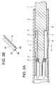
- Fig. 2A is a longitudinal cross sectional view of a telescopic shaft for vehicle steering according to a first embodiment of the present invention
- Fig. 2B is a perspective view of a leaf spring serving as an elastic member
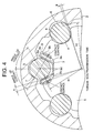
- Fig. 3 is a transverse cross sectional view, taken along the line X-X in Fig. 2A.
- the telescopic shaft for vehicle steering (hereinafter called the telescopic shaft) comprises a male shaft 1 and a female shaft 2 which are fitted to each other to be unrotatable and slidable.
- three grooves 3 are provided on the outer peripheral surface of the male shaft 1 at regular intervals of 120° in the circumferential direction to be extended in the axial direction.
- the axial grooves 5 which are extended in the axial direction at regular intervals of 120° in the circumferential direction.
- a plurality of spherical members 7 which are rigid bodies for rotating upon relative movement of the male and female shafts 1 and 2 in the axial direction are interposed to be rotatable.
- Each of the axial grooves 5 of the female shaft 2 has substantially an arch-shaped or Gothic arch-shaped cross section.
- the axial groove 3 extended in the axial direction of the male shaft 1 (hereinafter called the axial groove also) is constituted by a pair of flat side surfaces 3a which are inclined to diverge outwardly in the radial direction and a bottom surface 3b which is formed to be flat between these paired flat side surfaces 3a.
- a leaf spring 9 is interposed between the axial groove 3 of the male shaft 1 and the spherical member 7, for contacting the spherical member 7 and applying preload thereto.
- This leaf spring 9 has a unitary integral structure comprising flat-plate shaped contact portions 9a on the spherical member side each of which is in contact with the spherical member 7 at a point, flat-plate shaped contact portions 9b on the groove surface sides each of which is separated from the contact portion 9a on the spherical member side by a predetermined distance substantially in the circumferential direction and which is at the same time in contact with the flat side surface 3a of the axial groove 3 of the male shaft 1, biasing portions 9c each of which separates the contact portion 9a on the spherical member side and the contact portion 9b on the groove surface side from each other for elastically biasing both the contact portions 9a, 9b in the direction of separation, and a bottom portion 9d which is opposed to the bottom surface 3b of the axial groove 3 and is connected to the contact portions 9a, 9a on the spherical member side.
- the biasing portion 9c is in a folded form which is folded to be substantially U-shaped and substantially arch-shaped.
- the contact portion 9a on the spherical member side and the contact portion 9b on the groove surface are elastically biased by this folded-shaped biasing portion 9c to be separated from each other.
- three grooves 4 extended in the axial direction are provided on the outer peripheral surface of the male shaft 1 at regular intervals of 120° in the circumferential direction.
- three grooves 6 are provided on the inner peripheral surface of the female shaft 2, to be extended in the axial direction at regular intervals of 120° in the circumferential direction.
- a plurality of columnar members 8 which are rigid bodies for slidably moving upon relative movement of the male shaft 1 and the female shaft 2 in the axial direction are interposed with very small gaps therebetween.
- Each of the axial grooves 4 and 6 has substantially an arch-shaped or Gothic arch-shaped cross section.
- a stopper plate 10 with an annular elastic member is provided at an end of the male shaft 1.
- the spherical members 7, the columnar members 8 and the leaf springs are prevented from slipping off by this stopper plate 10 with the elastic member.
- a steel material containing 0.3% or more of carbon C and 0.3% or more of manganese Mn is employed as a material of the male shaft 1.
- the male shaft is formed to have the hardness of HV120 or more by cold forming and broaching.
- a solid lubricating film of MOS2, PTFE or the like may be applied on the surface of the male shaft 1.
- the female shaft 2 As a material of the female shaft 2, a steel material containing 0.2% or more of carbon C is employed.
- the female shaft 2 is formed to have the hardness of HV120 or more by cold forming and broaching.
- the axial grooves 5 and 6 are arranged in three to six rows.
- a solid lubricating film of MOS2, PTFE or the like may be applied on the surface of the female shaft 2.
- the leaf spring 9 is formed of SK material (S50C to 60C), SUS304 material, or the like, to have the hardness of HV 300 to 400.
- the surface treatment of the leaf spring 9 is performed by quenching and tempering, while the forming method thereof is pressing and secondary processing.
- the spherical member 7 is formed of SUJ2, ceramic, or the like, to have the hardness of HV 300 or more. Three to seven spherical members 7 are arranged in each of rows, and the diameter of each spherical member is 3mm to 7mm.
- the stopper plate 10 with the elastic member is formed by pressing, and is fixed by plastically deforming by caulking or clinching.
- the grease used in this case contains a solid lubricating material such as MOS2 or PTFE.
- the spherical member 7 is interposed between the male shaft 1 and the female shaft 2 and the spherical member 7 is preloaded to the extent that no backlash is generated with respect to the female shaft 2, it is possible to securely prevent backlash between the male shaft 1 and the female shaft 2 at the time of non-transmission of torque.
- the male shaft 1 and the female shaft 2 can slide with a stable sliding load with no backlash when they are moved in the axial direction relatively to each other.
- the leaf spring 9 is elastically deformed to restrain the spherical member 7 in the circumferential direction. Meanwhile, three rows of the columnar members 8 interposed between the male shaft 1 and the female shaft 2 mainly discharge the function of transmitting torque.
- the columnar members 8 are provided in addition to the spherical members 7, almost all of the load amount can be supported by the columnar members 8 when a great amount of torque is inputted. As a result, it is possible to reduce a contact pressure between the axial grooves 5 of the female shaft 2 and the spherical members 7 so as to improve the durability of the shaft. At the same time, when a torque load is great, it is possible to transmit the torque in a state of high rigidity.
- the spherical member 7 is preferably a ball of rigid body. It is also preferable that the columnar member 8 of rigid body is a needle roller.
- the columnar member (hereinafter called the needle roller) 8 receives a load thereof with a line contact, there can be obtained various advantages including that the contact pressure can be lowered, compared with the case with a ball which receives a load with a point contact. As a result, this arrangement is superior in the following points to a case in which all of the rows are in ball rolling structure.
- the needle rollers play the essential role for torque transmission between the male shaft 1 and the female shaft 2, and are brought into sliding contact with the inner peripheral surface of the female shaft 2.
- This structure is superior to the conventional structure which employs spline fitting in the following respects.
- German Patent DE3730393C2 and the first embodiment of the present invention will be compared to each other to be examined.
- Fig. 4 is a cross sectional view of an enlarged portion of the telescopic shaft for vehicle steering according to the first embodiment of the present invention, at a non-transmission time of torque.
- Fig. 5 is a cross sectional view of an enlarged portion of the telescopic shaft for vehicle steering according to the first embodiment of the present invention, at a transmission time of the torque.
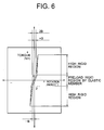
- Fig. 6 is a characteristic chart for showing the relationship between a steering angle (angle of rotation) of a steering wheel and a handle steering torque (torque of the steering wheel).
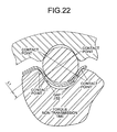
- Fig. 22 is a cross sectional view of an enlarged portion of a telescopic shaft for vehicle steering according to the German patent DE No. 3730393C2, at a non-transmission time of the torque.
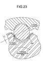
- Fig. 23 is a cross sectional view of an enlarged portion of the telescopic shaft for vehicle steering according to the German patent DE No. 3730393C2, at a transmission time of the torque.
- the contact portion 9a on the spherical member side of the leaf spring 9 can be sufficiently flexed through the biasing portion 9c, so that a flexural amount can be sufficiently kept.
- the columnar members 8 are provided in addition to the spherical members 7, the columnar members 8 are brought into contact with the axial grooves 4 and 6 of the male shaft 1 and the female shaft 2 before the leaf springs 9 at the time of transmission of toque, and the columnar members 8 can transmit the torque mainly. As a result, and excessive load (stress) is not applied on the spherical members 7 and the leaf springs 9.
- the male shaft 1 is rotated with respect to the female shaft 2 by the angle of rotation B, so that the columnar member 8 is brought into strong contact with the axial grooves 4 and 6 of the male shaft 1 and the female shaft 2 before the leaf spring 9, and the angle of rotation B becomes zero, as shown in Fig. 5.
- the leaf spring 9 is flexed and the actual angle of rotation B of the male shaft 1 with respect to the female shaft 2 in this portion becomes B so that the rotatable angle A remaining in this portion becomes (A - B). If the angle of rotation of the male shaft 1 becomes greater than that at the time of transmission of high toque, as seen from the graph of Fig. 6, the angle enters a region of high rigidity.
- This angle of rotation B is preferably set at 0.01° to 0.25° , partly because of the relationship with the circumferential gap present among the male shaft 1, a columnar member 8 and the female shaft 2.
- the columnar member 8 is required to have a gap necessary for sliding without resistance with respect to the male shaft 1 and the female shaft 2.
- a torque transmitting area defined by the male shaft 1, the leaf spring 9, the spherical member 7 and the female shaft 2 is required to be large. As a result, it is difficult to obtain satisfactory steering feeling with a touch of high rigidity.
- the upper limit of the circumferential gap (the angle of rotation B of the female shaft 2) present among the male shaft 1, the columnar member 8 and the female shaft 2 is preferably set as 0.25° .
- the lower limit of the gap is set as 2 ⁇ m since only a space necessary for sliding is required, which can be preferably converted into an angle of 0.01° .
- This angle of rotation B By setting this angle of rotation B, the relation between a steering angle of a steering wheel and a steering torque of the steering wheel is changed.
- This angle of rotation B is one-directional when rotation is given clockwise or anti-clockwise around the male shaft 1.
- rotation When rotation is bidirectional, the angle becomes double in a range from 0.02° to 0.5° .
- the minimum value for the angle of rotation B is to be set, it is required to take into consideration the condition that a sliding motion between the male shaft 1, the columnar member 8 and the female 2 should be performed smoothly. Then, by providing a gap among the male shaft 1, the columnar member 8 and the female shaft 2, the problem that the sliding resistance becomes very large when the female shaft 2 is slid can be solved.
- the minimum required gap for sliding the female shaft 2 is determined as 2 ⁇ m. However, when there is a curve on the male shaft 1 or the female shaft 2 or a fluctuation of inner or outer diameter of either shaft in the axial direction, it is particularly required to keep the minimum gap of 2 ⁇ m in order to prevent increase in the sliding resistance.
- the minimum value for the angle of rotation B is set as 0.01° by calculating back from an outer diameter value which is appropriate for the male shaft (steering shaft )1.
- the outer diameter of the male shaft 1 is set such that the torque non-transmitting state is changed to the torque transmitting state and the radius of a portion at which the columnar member 8 is brought in contact with the groove of the female shaft 2 is R2, and that the radius of a portion at which the leaf spring 9 is brought in contact with the spherical member 7 is R1 when the leaf spring 9 is flexed at the torque transmitting time, and opposed portions of the leaf spring 9 come closest to each other.
- a torque value at a point at which the torque is shifted into a preload rigid region by the leaf spring 9 is preferably not less than +2Nm and not more than -2Nm.
- a difference between a region of low rigidity and a region of high rigidity is one reason for that. It is not desirable that the driver senses backlash or noise of the steering system, or a delay of response from the vehicle for a steering operation. In case of a simple spline structure of the prior art, if there is a gap between the male spline shaft and the female spline shaft, the driver senses backlash. In order to prevent this phenomenon, it is required to remove a gap area by means of preload by the leaf spring 9.
- the male shaft 1 is rotated by the angle B in the positive direction (e.g. clockwise) or by the angle B in the negative direction (e.g. anti-clockwise), there is a possibility that the male shaft 1 can be rotated still a little further in either the positive direction or the negative direction at the time of transmission of high torque, which turns to be a region of high rigidity for steering.
- the angle of rotation of the male shaft 1 in the positive or negative direction in the preload rigid region is 2B.
- the leaf spring 9 can secure a sufficient flexural amount and no excessive load (stress) is applied on the spherical member 7 and the leaf spring 9, the stress generated in the contact portion between the spherical member 7 and the leaf spring 9 at the time of torque transmission can be reduced. As a result, not great stress is generated in the leaf spring 9 portion, so that "the worn-out condition" due to permanent deformation of the leaf spring 9 can be avoided and a satisfactory preload performance can be maintained for a long term.
- Fig. 4 it is arranged such that, at the time of non-transmission of torque, small gaps are formed between the columnar member 8 and the bottom portion of the axial groove 4 of the male shaft 1 and between the columnar member 8 and the bottom portion of the axial groove 6 of the female shaft 2, but the columnar member 8 is brought into contact with the axial grooves 4 and 6 at both the end portions thereof.
- a cross section of the axial groove of the male shaft on which the leaf spring is provided has an arch shape having a curvature, and the leaf spring is also in an arch shape having a curvature.
- the respective curvatures are differed to give the leaf spring a spring nature. For this reason, a contact point between the leaf spring and the male shaft is located at a corner of the male shaft, as shown in Fig. 22.
- Fig. 23 when torque is loaded, the whole leaf spring slides sideways so that the transmitted torque may be reduced or hysteresis may be excessively generated.
- the axial groove 3 of the male shaft 1 is formed of flat surfaces.
- the center of the axial groove 3 is consistent with the center of the male shaft 1, and the axial groove 3 has a wedge-form which is bilaterally symmetrical with respect to the center of the axial groove 3.
- An angle of the wedge is preferably 40° to 70° with respect to the center of the axial groove 3.
- German Patent DE No. 3730393C2 shown in Figs. 22 and 23 when the torque is not loaded, the contact points between the male shaft, the spherical member, the leaf spring and the female shaft are not on the same line so that, with gradual loading of the torque, the contact angle changes. As a result, there is a fear that not only the linear torsional property required for the steering shaft can not be obtained, but also an appropriate hysteresis can not be obtained.
- Fig. 7A, Fig. 7B and Fig. 7C are schematic views each showing a flexural state of the leaf spring which is used in each of the embodiments of the present invention.
- Fig. 24A and Fig. 24B are respectively schematic views each for showing a flexural state of a leaf spring used in the German patent DE No. 3730393C2.
- Fig. 24 shows model examples in which the leaf spring disclosed in the German patent DE No. 3730393C2 is illustrated in a simplified manner.
- Fig. 24A shows a case in which an appropriate preload is expected to be applied in a state where no torque is loaded. In this case, a distance (C2) from the leaf spring to the axial groove is a stroke for allowing generation of preload as a spring.
- Fig. 24B when load (F1) is further applied at two points, the leaf spring is flexed, and is presently brought into contact with side surfaces of the axial groove. With this arrangement, it is required to receive the whole torque at points in contact with balls. As a result, a flexural amount ( ⁇ S2) of the leaf spring can not be made great, so that it is presumably difficult for the leaf spring to have the life required as a steering shaft. In this case, C2 ⁇ ⁇ S2.
- the distance between the contact portion 9a on the spherical member side of the leaf spring 9 and the contact portion 9b on the groove surface side is set as (C1).
- the load (F1) is applied in this state on two points (corresponding to the contact portion 9a on the spherical member side)
- the elastic member can be flexed sufficiently, so that a sufficient flexural amount ( ⁇ S1) can be secured.
- ⁇ S1 a sufficient flexural amount
- the distance between the contact portion 9a on the spherical member side of the leaf spring 9 and the contact portion 9b on the groove surface side is set as (C1), and the biasing portion 9c is formed of a material such as rubber or synthetic resin other than the material of these contact portions 9a and 9b.
- the load (F1) is applied in this state on the two points (corresponding to the contact portion 9a on the spherical member side)
- the elastic member can be flexed sufficiently, so that a sufficient flexural amount ( ⁇ S1) can be secured.
- ⁇ S1 a sufficient flexural amount
- the whole leaf spring 9 hardly slides sideways when the torque is applied.
- the bottom portion 9d of the leaf spring 9 can shift sideways a little with respect to the bottom surface 3b of the axial groove 3.
- the leaf spring 9 is arranged such that the bottom portion 9d thereof is in a state of contacting with the bottom surface 3b of the axial groove 3, in the same manner as in the first embodiment, or that the distance thereof with the bottom portion 3b of the axial groove 3 is set as predetermined, in the same manner as in a second embodiment which will be described later.
- the hysteresis is required to be changed depending on a matched condition with the steering performance of each vehicle. Specifically, if the bottom portion 9d of the leaf spring 9 is set to be in a state of contacting with the bottom surface 3b of the axial groove 3, a friction is produced when the axial groove 3 and the leaf spring 9 are moved relatively to each other, so that the hysteresis can be set as comparatively large.
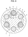
- Fig. 8 is a transverse cross sectional view of a telescopic shaft for vehicle steering according to the second embodiment of the present invention (corresponding to the transverse cross sectional view, taken along the line X-X in Fig. 2A).
- the second embodiment is substantially the same as the first embodiment described above, in which the bottom surface 3b of the axial groove 3 is separated from the bottom portion 9d of the leaf spring 9 by a predetermined distance.
- the hysteresis can be controlled and no friction is caused when the axial groove 3 and the leaf spring 9 are moved relatively to each other, so that the hysteresis can be set as comparatively small.
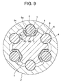
- Fig. 9 is a transverse cross sectional view of a telescopic shaft for vehicle steering according to a third embodiment of the present invention (corresponding to the transverse cross sectional view, taken along the line X-X in Fig. 2A).
- the third embodiment is substantially the same as the second embodiment described above, in which, in the leaf spring 9, the contact portion 9a on the spherical member side is formed at the end of the folded portion of the leaf spring 9, while the contact portion 9b is formed in a middle of the folded portion of the leaf spring 9.
- the bottom surface 3b of the axial groove 3 is separated from the bottom portion 9d of the leaf spring 9 by a predetermined distance.
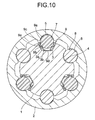
- Fig. 10 is a transverse cross sectional view of a telescopic shaft for vehicle steering according to a fourth embodiment of the present invention (corresponding to the transverse cross sectional view, taken along the line X-X in Fig. 2A).
- the fourth embodiment is substantially the same as the first embodiment described above, in which, in the leaf spring 9, protruding portions 9e protruded toward the contact portions 9b on the groove surface side are formed on the contact portions 9a on the spherical member side.
- the bottom portion 9d of the leaf spring 9 is provided in a state of contacting with the bottom surface 3b of the axial groove 3.
- the hysteresis can be controlled and friction is caused when the axial groove 3 and the leaf spring 9 are moved relatively to each other, so that the hysteresis can be set as comparatively great.
- Fig. 11 is a transverse cross sectional view of a telescopic shaft for vehicle steering according to a fifth embodiment of the present invention (corresponding to the transverse cross sectional view, taken along the line X-X in Fig. 2A).
- the fifth embodiment is substantially the same as the fourth embodiment described above, in which the bottom surface 3b of the axial groove 3 is separated from the bottom portion 9d of the leaf spring 9 by a predetermined distance.
- the hysteresis can be controlled and no friction is caused when the axial groove 3 and the leaf spring 9 are moved relatively to each other, so that the hysteresis can be set as comparatively small.
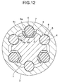
- Fig. 12 is a transverse cross sectional view of a telescopic shaft for vehicle steering according to a sixth embodiment of the present invention (corresponding to the transverse cross sectional view, taken along the line X-X in Fig. 2A).
- the sixth embodiment is substantially the same as the first embodiment described above, in which, in the leaf spring 9, the tip end of each contact portion 9b on the axial groove side is folded back inward so as to be contacted with the contact portion 9a on the spherical member side.
- the rigidity of the leaf spring 9 can be enhanced, and the torsional rigidity can also be enhanced.
- Fig. 13 is a transverse cross sectional view of a telescopic shaft for vehicle steering according to a seventh embodiment of the present invention (corresponding to the transverse cross sectional view, taken along the line X-X in Fig. 2A).
- the seventh embodiment is substantially the same as the sixth embodiment described above, in which the bottom surface 3b of the axial groove 3 is separated from the bottom portion 9d of the leaf spring 9 by a predetermined distance.
- the hysteresis can be controlled and no friction is caused when the axial groove 3 and the leaf spring 9 are moved relatively to each other, so that the hysteresis can be set as comparatively small.
- Fig. 14 is a transverse cross sectional view of a telescopic shaft for vehicle steering according to an eighth embodiment of the present invention (corresponding to the transverse cross sectional view, taken along the line X-X in Fig. 2A).
- the eighth embodiment is substantially the same as the third embodiment described above, in which, in the leaf spring 9, the contact portion 9a on the spherical member side is formed on the end side of each folded portion of the leaf spring 9, while the contact portion 9b on the groove surface is formed in a middle of each folded portion of the leaf spring 9. Also in this case, the same function and effect as those in the third embodiment described above can be obtained.
- each contact portion 9a on the spherical member side is folded back outward so as to be in contact with the contact portion 9a on the spherical member side.
- the rigidity of the leaf spring 9 can be enhanced, and the torsional rigidity can also be enhanced.
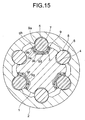
- Fig. 15 is a transverse cross sectional view of a telescopic shaft for vehicle steering according to a ninth embodiment of the present invention (corresponding to the transverse cross sectional view, taken along the line X-X in Fig. 2A).
- the ninth embodiment is substantially the same as the first embodiment described above, in which, in the leaf spring 9, the biasing portion 9c in the folded-back form is abolished, and a pair of contact portions 9a on the spherical member side are formed by an inner side plate 9f folded back substantially in a U shape.
- a pair of contact portions 9b on the groove surface sides are formed by an outer side plate 9g folded back substantially in a U shape.
- a biasing portion 9h which is formed of a different elastic material such as rubber or synthetic resin is interposed between a flat surface portion of the inner side plate 9f and a flat surface portion of the outer side plate 9g.
- the hysteresis can be controlled and friction is caused when the inner side plate 9f and the outer side plate 9g are moved relatively to each other, so that the hysteresis can be set as comparatively great.
- Fig. 16 is a transverse cross sectional view of a telescopic shaft for vehicle steering according to a tenth embodiment of the present invention (corresponding to the transverse cross sectional view, taken along the line X-X in Fig. 2A).
- the tenth embodiment is substantially the same as the ninth embodiment described above, in which a slight space is present between the bottom flat surface of the inner side plate 9f and the bottom flat surface of the outer side plate 9g, and the both side plates are set in a non-contact state.
- the hysteresis can be controlled and no friction is caused when the inner side plate 9f and the outer side plate 9g are moved relatively to each other, so that the hysteresis can be set as comparatively small.
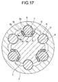
- Fig. 17 is a transverse cross sectional view of a telescopic shaft for vehicle steering according to an eleventh embodiment of the present invention (corresponding to the transverse cross sectional view, taken along the line X-X in Fig. 2A).
- the eleventh embodiment is substantially the same as the first embodiment described above, except that in the leaf spring 9, a second biasing portion 9j which is formed of a different material such as rubber or synthetic resin is interposed between the contact portion 9a on the spherical member side and the contact portion 9b on the groove surface side.
- a second biasing portion 9j which is formed of a different material such as rubber or synthetic resin is interposed between the contact portion 9a on the spherical member side and the contact portion 9b on the groove surface side.
- Fig. 18 is a transverse cross sectional view of a telescopic shaft for vehicle steering according to a twelfth embodiment of the present invention (corresponding to the transverse cross sectional view, taken along the line X-X in Fig. 2A).
- the twelfth embodiment is substantially the same as the second embodiment described above, in which, in the leaf spring 9, the second biasing portion 9j which is formed of a different material such as rubber or synthetic resin is interposed between the contact portion 9a on the spherical member side and the contact portion 9b on the groove surface side.
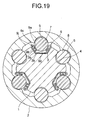
- Fig. 19 is a transverse cross sectional view of a telescopic shaft for vehicle steering according to a thirteenth embodiment of the present invention (corresponding to the transverse cross sectional view, taken along the line X-X in Fig. 2A).
- the thirteenth embodiment is substantially the same as the third embodiment described above, except that in the leaf spring 9, the second biasing portion 9j which is formed of a different material such as rubber or synthetic resin is interposed between the contact portion 9a on the spherical member side and the contact portion 9b on the groove surface side.
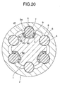
- Fig. 20 is a transverse cross sectional view of a telescopic shaft for vehicle steering according to a fourteenth embodiment of the present invention (corresponding to the transverse cross sectional view, taken along the line X-X in Fig. 2A).
- the fourteenth embodiment is substantially the same as the ninth or tenth embodiment described above, in which, in the leaf spring 9, a pair of contact portions 9a on the spherical member side are composed of inner side plates constituted by two plates, while a pair of contact portions 9b on the groove surface sides are composed of an outer side plate 9g folded substantially in a U shape.
- the biasing portion 9h formed of a different elastic material such as rubber or synthetic resin is interposed between these side plates.
- Fig. 21 is a transverse cross sectional view of a telescopic shaft for vehicle steering according to a fifteenth embodiment of the present invention (corresponding to the transverse cross sectional view, taken along the line X-X in Fig. 2A).
- the fifteenth embodiment is substantially the same as the first embodiment described above except that the leaf spring 9 is provided on the female shaft 2 side.
- the axial groove 5 of the female shaft 2 is comprised of a pair of slanting flat-shaped side surfaces 5a and a bottom surface 5b formed to be flat between these paired flat-shaped side surfaces 5a.
- a leaf spring 9 which is brought into contact with the spherical member 7 for preload is interposed between the axial groove 5 of the female shaft 2 and the spherical member 7.
- This leaf spring 9 comprises contact portions 9a on the spherical member side which are in contact with the spherical member 7 at two points, contact portions 9b on the groove surface sides each is separated from the contact portion 9a on the spherical member side by a predetermined distance in the substantially circumferential direction and is in contact with the flat-shaped side surface 5a of the axial groove 5 of the female shaft 2, a biasing portion 9c for elastically biasing the contact portion 9a on the spherical member side and the contact portion 9b on the groove surface side in a direction in which they are separated from each other, and a bottom portion 9d which is opposed to the bottom surface 5b of the axial groove 5.
- This biasing portion 9c is folded back to be substantially U-shaped and in substantially arch-shaped.
- the contact portion 9a on the spherical member side and the contact portion 9b on the groove surface side can be elastically biased by this folded-back biasing portion 9c in a direction in which both the contact portions are separated from each other.
Landscapes
- Engineering & Computer Science (AREA)
- General Engineering & Computer Science (AREA)
- Mechanical Engineering (AREA)
- Chemical & Material Sciences (AREA)
- Combustion & Propulsion (AREA)
- Transportation (AREA)
- Ocean & Marine Engineering (AREA)
- Steering Controls (AREA)
Applications Claiming Priority (3)
| Application Number | Priority Date | Filing Date | Title |
|---|---|---|---|
| JP2003004774 | 2003-01-10 | ||
| JP2003004774 | 2003-01-10 | ||
| PCT/JP2004/000056 WO2004062981A1 (fr) | 2003-01-10 | 2004-01-08 | Arbre telescopique pour direction de vehicule a moteur |
Publications (2)
| Publication Number | Publication Date |
|---|---|
| EP1588921A1 true EP1588921A1 (fr) | 2005-10-26 |
| EP1588921A4 EP1588921A4 (fr) | 2006-11-29 |
Family
ID=32708977
Family Applications (1)
| Application Number | Title | Priority Date | Filing Date |
|---|---|---|---|
| EP04700759A Withdrawn EP1588921A4 (fr) | 2003-01-10 | 2004-01-08 | Arbre telescopique pour direction de vehicule a moteur |
Country Status (5)
| Country | Link |
|---|---|
| US (1) | US20060156855A1 (fr) |
| EP (1) | EP1588921A4 (fr) |
| JP (1) | JPWO2004062981A1 (fr) |
| CN (1) | CN1747867A (fr) |
| WO (1) | WO2004062981A1 (fr) |
Cited By (10)
| Publication number | Priority date | Publication date | Assignee | Title |
|---|---|---|---|---|
| EP1652748A1 (fr) * | 2003-07-02 | 2006-05-03 | NSK Ltd. | Arbre telescopique destine a la direction d'un vehicule a moteur |
| EP1800795A3 (fr) * | 2005-12-22 | 2007-08-15 | Doosan Infracore Co., Ltd. | Dispositif de décharge de pièces avec un arbre cannelé |
| US7416216B2 (en) | 2002-11-29 | 2008-08-26 | Nsk Ltd. | Telescopic shaft for vehicle steering |
| US7416199B2 (en) | 2003-02-06 | 2008-08-26 | Nsk Ltd. | Steering device for motor vehicle |
| US7429060B2 (en) | 2002-06-11 | 2008-09-30 | Nsk Ltd. | Telescopic shaft for steering of vehicle, and telescopic shaft for steering of vehicle with cardan shaft joint |
| US7481130B2 (en) | 2001-10-01 | 2009-01-27 | Nsk Ltd. | Vehicle steering telescopic shaft |
| US7559267B2 (en) | 2002-10-02 | 2009-07-14 | Nsk Ltd. | Extendable shaft for vehicle steering |
| WO2009138070A1 (fr) * | 2008-05-15 | 2009-11-19 | Neumayer Tekfor Holding Gmbh | Unité de déplacement |
| US8075412B2 (en) | 2008-06-20 | 2011-12-13 | Neumayer Tekfor Holding Gmbh | Displacement unit |
| EP2213410A3 (fr) * | 2009-02-03 | 2012-11-28 | Ab Skf | Guidage linéaire avec dispositif de serrage |
Families Citing this family (26)
| Publication number | Priority date | Publication date | Assignee | Title |
|---|---|---|---|---|
| JP4696916B2 (ja) * | 2004-01-27 | 2011-06-08 | 日本精工株式会社 | 車両ステアリング用伸縮軸 |
| JP4921762B2 (ja) * | 2005-09-30 | 2012-04-25 | 株式会社ジェイテクト | 伸縮自在シャフトおよび車両操舵用伸縮自在シャフト |
| ATE538016T1 (de) * | 2005-10-12 | 2012-01-15 | Renault Trucks | Fahrzeug mit einer lenksäule |
| JP4793030B2 (ja) * | 2006-03-06 | 2011-10-12 | 日本精工株式会社 | ステアリング装置用の伸縮軸 |
| US8182354B2 (en) | 2007-12-03 | 2012-05-22 | Mando Corporation | Slip joint of steering apparatus for vehicle |
| DE102008034805B3 (de) * | 2008-07-24 | 2010-04-15 | Getrag Ford Transmissions Gmbh | Kupplungsvorrichtung zur Übertragung einer Drehbewegung mit Federelement |
| CN102700608B (zh) * | 2012-06-27 | 2013-11-20 | 山西大运汽车制造有限公司 | 大范围伸缩式转向传动轴 |
| CN103223972A (zh) * | 2013-05-04 | 2013-07-31 | 范茂荣 | 汽车动力转向限位器 |
| WO2015191309A1 (fr) * | 2014-06-12 | 2015-12-17 | Borgwarner Inc. | Procédé d'accouplement de dispositif de mise en phase électrique |
| JP6146539B2 (ja) * | 2014-07-03 | 2017-06-14 | 日本精工株式会社 | 伸縮式回転伝達軸 |
| JP6455703B2 (ja) * | 2014-09-04 | 2019-01-23 | 株式会社ジェイテクト | インターミディエートシャフト |
| CN106627734B (zh) * | 2015-09-06 | 2019-07-23 | 北京宝沃汽车有限公司 | 转向管柱的芯轴组件 |
| JP6622653B2 (ja) * | 2016-06-06 | 2019-12-18 | 株式会社ジェイテクト | スプライン伸縮軸の製造方法 |
| DE102016218830A1 (de) * | 2016-09-29 | 2018-03-29 | Aktiebolaget Skf | Baueinheit |
| DE102016222795A1 (de) * | 2016-11-18 | 2018-05-24 | Thyssenkrupp Ag | Lenkwelle für ein Kraftfahrzeug |
| DE102017207015A1 (de) | 2017-02-27 | 2018-08-30 | Thyssenkrupp Ag | Gleitlager für eine Lenkspindel und Lenksäule für ein Kraftfahrzeug |
| DE102017209167A1 (de) * | 2017-05-31 | 2018-12-06 | Thyssenkrupp Ag | Lenkwelle für ein Kraftfahrzeug |
| CN107444471B (zh) * | 2017-07-31 | 2019-05-07 | 安徽江淮汽车集团股份有限公司 | 转向传动轴连接结构 |
| JP6991658B2 (ja) * | 2017-11-30 | 2022-01-12 | 株式会社山田製作所 | ステアリング装置 |
| CN108357561B (zh) * | 2018-02-12 | 2020-01-14 | 安徽江淮汽车集团股份有限公司 | 长度可调的转向传动轴组件 |
| CN108327779B (zh) * | 2018-02-12 | 2019-10-25 | 安徽江淮汽车集团股份有限公司 | 长度可调的转向传动轴组件 |
| CN108340963B (zh) * | 2018-02-12 | 2020-01-14 | 安徽江淮汽车集团股份有限公司 | 长度可调的转向传动轴组件 |
| CN108357557B (zh) * | 2018-02-12 | 2019-10-25 | 安徽江淮汽车集团股份有限公司 | 长度可调的转向传动轴组件 |
| CN108327777B (zh) * | 2018-02-12 | 2020-01-14 | 安徽江淮汽车集团股份有限公司 | 长度可调的转向传动轴组件 |
| DE102018120628A1 (de) * | 2018-08-23 | 2020-02-27 | Trw Automotive Gmbh | Lagervorrichtung für Kraftfahrzeugwellen sowie Kraftfahrzeugwellenbaugruppe für ein Kraftfahrzeug |
| CN109296639B (zh) * | 2018-12-06 | 2023-03-31 | 株洲易力达机电有限公司 | 新型滑动副总成 |
Citations (1)
| Publication number | Priority date | Publication date | Assignee | Title |
|---|---|---|---|---|
| EP1512607A1 (fr) * | 2002-06-11 | 2005-03-09 | NSK Ltd. | Arbre telescopique permettant de diriger un vehicule et arbre telescopique permettant de diriger un vehicule au moyen d'un accouplement d'arbre a cardan |
Family Cites Families (14)
| Publication number | Priority date | Publication date | Assignee | Title |
|---|---|---|---|---|
| US3392599A (en) * | 1966-12-30 | 1968-07-16 | Gen Motors Corp | Energy absorbing device |
| CH553350A (fr) * | 1972-06-20 | 1974-08-30 | Betrix Claude | Dispositif de guidage du deplacement axial d'un organe cylindrique. |
| DE3730393C2 (de) | 1987-09-10 | 1994-01-13 | Lemfoerder Metallwaren Ag | Lenkwelle für Kraftfahrzeuge, bestehend aus axial ineinander verschieblichen Wellenteilen |
| US4886295A (en) * | 1988-12-05 | 1989-12-12 | General Motors Corporation | Vehicle occupant protection system |
| JP2538390Y2 (ja) * | 1991-04-22 | 1997-06-11 | 富士機工株式会社 | 伸縮自在シャフト |
| US5460574A (en) * | 1993-08-31 | 1995-10-24 | Trw Inc. | Variable length shaft assembly with a lash bushing |
| US5709605A (en) * | 1996-12-23 | 1998-01-20 | General Motors Corporation | Shaft coupling |
| DE19824477A1 (de) * | 1998-05-30 | 1999-12-02 | Daimler Chrysler Ag | Teleskopische Lenkwelle für Kraftfahrzeuge |
| ES2161127B1 (es) * | 1999-03-16 | 2002-09-01 | Castellon Melchor Daumal | Arbol telescopico para columnas de direccion en vehiculos de automoviles con sistema de deslizamiento con control de carga. |
| FR2795785B1 (fr) * | 1999-06-30 | 2002-06-28 | Nacam | Dispositif d'accouplement a billes de deux arbres coulissants |
| EP1106851B1 (fr) * | 1999-12-10 | 2001-08-01 | SKF LINEARSYSTEME GmbH | Palier à roulement pour mouvements longitudinaux |
| JP2001239944A (ja) * | 2000-03-01 | 2001-09-04 | Nsk Ltd | 伸縮自在シャフトの結合構造 |
| US6505969B2 (en) * | 2001-01-31 | 2003-01-14 | The Torrington Company | Interlocking linear roller bearing |
| US6620050B2 (en) * | 2001-10-30 | 2003-09-16 | Mando Corporation | Universal joint |
-
2004
- 2004-01-08 CN CNA2004800039097A patent/CN1747867A/zh active Pending
- 2004-01-08 US US10/541,870 patent/US20060156855A1/en not_active Abandoned
- 2004-01-08 WO PCT/JP2004/000056 patent/WO2004062981A1/fr not_active Application Discontinuation
- 2004-01-08 EP EP04700759A patent/EP1588921A4/fr not_active Withdrawn
- 2004-01-08 JP JP2005507968A patent/JPWO2004062981A1/ja not_active Withdrawn
Patent Citations (1)
| Publication number | Priority date | Publication date | Assignee | Title |
|---|---|---|---|---|
| EP1512607A1 (fr) * | 2002-06-11 | 2005-03-09 | NSK Ltd. | Arbre telescopique permettant de diriger un vehicule et arbre telescopique permettant de diriger un vehicule au moyen d'un accouplement d'arbre a cardan |
Non-Patent Citations (1)
| Title |
|---|
| See also references of WO2004062981A1 * |
Cited By (12)
| Publication number | Priority date | Publication date | Assignee | Title |
|---|---|---|---|---|
| US7481130B2 (en) | 2001-10-01 | 2009-01-27 | Nsk Ltd. | Vehicle steering telescopic shaft |
| US7429060B2 (en) | 2002-06-11 | 2008-09-30 | Nsk Ltd. | Telescopic shaft for steering of vehicle, and telescopic shaft for steering of vehicle with cardan shaft joint |
| US7559267B2 (en) | 2002-10-02 | 2009-07-14 | Nsk Ltd. | Extendable shaft for vehicle steering |
| US7416216B2 (en) | 2002-11-29 | 2008-08-26 | Nsk Ltd. | Telescopic shaft for vehicle steering |
| US7416199B2 (en) | 2003-02-06 | 2008-08-26 | Nsk Ltd. | Steering device for motor vehicle |
| EP1652748A1 (fr) * | 2003-07-02 | 2006-05-03 | NSK Ltd. | Arbre telescopique destine a la direction d'un vehicule a moteur |
| EP1652748A4 (fr) * | 2003-07-02 | 2007-07-18 | Nsk Ltd | Arbre telescopique destine a la direction d'un vehicule a moteur |
| US7404768B2 (en) | 2003-07-02 | 2008-07-29 | Nsk Ltd. | Telescopic shaft for motor vehicle steering |
| EP1800795A3 (fr) * | 2005-12-22 | 2007-08-15 | Doosan Infracore Co., Ltd. | Dispositif de décharge de pièces avec un arbre cannelé |
| WO2009138070A1 (fr) * | 2008-05-15 | 2009-11-19 | Neumayer Tekfor Holding Gmbh | Unité de déplacement |
| US8075412B2 (en) | 2008-06-20 | 2011-12-13 | Neumayer Tekfor Holding Gmbh | Displacement unit |
| EP2213410A3 (fr) * | 2009-02-03 | 2012-11-28 | Ab Skf | Guidage linéaire avec dispositif de serrage |
Also Published As
| Publication number | Publication date |
|---|---|
| CN1747867A (zh) | 2006-03-15 |
| WO2004062981A1 (fr) | 2004-07-29 |
| JPWO2004062981A1 (ja) | 2006-05-18 |
| US20060156855A1 (en) | 2006-07-20 |
| EP1588921A4 (fr) | 2006-11-29 |
Similar Documents
| Publication | Publication Date | Title |
|---|---|---|
| EP1588921A1 (fr) | Arbre telescopique pour direction de vehicule a moteur | |
| US7416216B2 (en) | Telescopic shaft for vehicle steering | |
| JP4258470B2 (ja) | 車両ステアリング用伸縮軸、及びカルダン軸継手付き車両ステアリング用伸縮軸 | |
| US7416199B2 (en) | Steering device for motor vehicle | |
| US7338382B2 (en) | Extendable vehicle steering shaft | |
| EP1693579A2 (fr) | Arbre télescopique | |
| EP1547903B1 (fr) | Arbre telescopique de guidage de vehicule | |
| US7559267B2 (en) | Extendable shaft for vehicle steering | |
| US20040245759A1 (en) | Vehicle steering telescopic shaft | |
| US20070157754A1 (en) | Telescopic shaft for vehicle steering | |
| EP1557338A1 (fr) | Arbre extensible pour le guidage d'un vehicule | |
| EP1584538A1 (fr) | Arbre telescopique pour direction de vehicule automobile | |
| US7404768B2 (en) | Telescopic shaft for motor vehicle steering | |
| US20090203455A1 (en) | Extendable Shaft and Motor Vehicle Steering Apparatus | |
| JP4544252B2 (ja) | 車両ステアリング用伸縮軸、及びカルダン軸継手付き車両ステアリング用伸縮軸 | |
| JP2007191149A5 (fr) | ||
| JP2003063414A (ja) | 車両ステアリング用伸縮軸 |
Legal Events
| Date | Code | Title | Description |
|---|---|---|---|
| PUAI | Public reference made under article 153(3) epc to a published international application that has entered the european phase |
Free format text: ORIGINAL CODE: 0009012 |
|
| 17P | Request for examination filed |
Effective date: 20050805 |
|
| AK | Designated contracting states |
Kind code of ref document: A1 Designated state(s): AT BE BG CH CY CZ DE DK EE ES FI FR GB GR HU IE IT LI LU MC NL PT RO SE SI SK TR |
|
| AX | Request for extension of the european patent |
Extension state: AL LT LV MK |
|
| DAX | Request for extension of the european patent (deleted) | ||
| RBV | Designated contracting states (corrected) |
Designated state(s): DE GB |
|
| A4 | Supplementary search report drawn up and despatched |
Effective date: 20061026 |
|
| RIC1 | Information provided on ipc code assigned before grant |
Ipc: B62D 1/20 20060101ALI20061020BHEP Ipc: B62D 1/16 20060101AFI20061020BHEP |
|
| STAA | Information on the status of an ep patent application or granted ep patent |
Free format text: STATUS: THE APPLICATION HAS BEEN WITHDRAWN |
|
| 18W | Application withdrawn |
Effective date: 20070124 |