EP1652710A2 - Dicht- oder Zierstreifen, insbesondere für Kraftfahrzeuge - Google Patents
Dicht- oder Zierstreifen, insbesondere für Kraftfahrzeuge Download PDFInfo
- Publication number
- EP1652710A2 EP1652710A2 EP05109023A EP05109023A EP1652710A2 EP 1652710 A2 EP1652710 A2 EP 1652710A2 EP 05109023 A EP05109023 A EP 05109023A EP 05109023 A EP05109023 A EP 05109023A EP 1652710 A2 EP1652710 A2 EP 1652710A2
- Authority
- EP
- European Patent Office
- Prior art keywords
- sealing
- decorative strip
- strip according
- carrier profile
- cover plate
- Prior art date
- Legal status (The legal status is an assumption and is not a legal conclusion. Google has not performed a legal analysis and makes no representation as to the accuracy of the status listed.)
- Granted
Links
Images


Classifications
-
- B—PERFORMING OPERATIONS; TRANSPORTING
- B60—VEHICLES IN GENERAL
- B60J—WINDOWS, WINDSCREENS, NON-FIXED ROOFS, DOORS, OR SIMILAR DEVICES FOR VEHICLES; REMOVABLE EXTERNAL PROTECTIVE COVERINGS SPECIALLY ADAPTED FOR VEHICLES
- B60J10/00—Sealing arrangements
- B60J10/70—Sealing arrangements specially adapted for windows or windscreens
- B60J10/74—Sealing arrangements specially adapted for windows or windscreens for sliding window panes, e.g. sash guides
- B60J10/75—Sealing arrangements specially adapted for windows or windscreens for sliding window panes, e.g. sash guides for sealing the lower part of the panes
-
- B—PERFORMING OPERATIONS; TRANSPORTING
- B60—VEHICLES IN GENERAL
- B60J—WINDOWS, WINDSCREENS, NON-FIXED ROOFS, DOORS, OR SIMILAR DEVICES FOR VEHICLES; REMOVABLE EXTERNAL PROTECTIVE COVERINGS SPECIALLY ADAPTED FOR VEHICLES
- B60J10/00—Sealing arrangements
- B60J10/20—Sealing arrangements characterised by the shape
- B60J10/26—Sealing arrangements characterised by the shape characterised by the surface shape
- B60J10/265—Sealing arrangements characterised by the shape characterised by the surface shape the surface being primarily decorative
-
- B—PERFORMING OPERATIONS; TRANSPORTING
- B60—VEHICLES IN GENERAL
- B60J—WINDOWS, WINDSCREENS, NON-FIXED ROOFS, DOORS, OR SIMILAR DEVICES FOR VEHICLES; REMOVABLE EXTERNAL PROTECTIVE COVERINGS SPECIALLY ADAPTED FOR VEHICLES
- B60J10/00—Sealing arrangements
- B60J10/30—Sealing arrangements characterised by the fastening means
Definitions
- the invention relates to a sealing or decorative strip, which is used in particular for motor vehicles.
- the sealing or decorative strip is provided with a carrier profile, which is made of an elastically deformable material and having an end portion.
- the sealing or decorative strip is provided with a trim strip, which is fastened to the carrier profile and has an inner surface and an outer surface.
- An end cap is disposed at the end portion and covers a gap existing between the carrier profile and the inner surface.
- a sealing or ornamental strip for example, enclosing a window of a motor vehicle, serves on the one hand to seal the window.
- the sealing or decorative strip has the function of giving the border of the window pane an aesthetically pleasing appearance.
- the sealing or decorative strip on a trim strip, the observer facing outer surface is usually designed dull or shiny and which is attached to a support profile.
- the carrier profile may be part of a seal which seals the window pane, as is known from WO 2004/056598 A1.
- an end cap which covers a gap present between the carrier profile and the inner surface of the trim strip and thus forms a shapely conclusion.
- the usually made of plastic end cap is usually either materially connected to the carrier profile, for example by injection molding, or plugged into the trim.
- the latter requires a special shape of the trim, which limits the freedom of design.
- DT 2 018 864 discloses an end cap which is provided with a lug on which rests the inner surface of a decorative strip.
- the end cap also has a groove which receives the edge of the trim strip and resilient clamping means by which the end cap is attachable to a flange.
- the groove is in a straight line with a Einlegerille a seal, which is also fastened to the flange.
- the end piece has a C-shaped bracket portion, which serves to connect a seal and a cross-sectionally L-shaped gutter with each other.
- the clip portion has an upper leg which bears against the top of a bottom plate of the gutter and a lower leg which bears against the underside of the gasket.
- the upper leg is provided on its upper side with a groove into which engages a projection of the seal during insertion of the clip portion into a cavity formed by the seal to guide the clip portion. both sides the groove are arranged on the upper side of the upper leg and cam, which abut in the inserted state of the clip portion of the projection surrounding the inner surface of the seal.
- the cams serve to increase the frictional engagement between the upper leg of the clip portion and the seal.
- the invention has the object of developing a sealing or decorative strip of the type mentioned in that can achieve a reliable attachment of the end cap with a relatively simple installation.
- the inventive sealing or decorative strip is based on the knowledge to assemble the end cap of a cover plate and a fastening part, which conveniently adapted to the contour of the trim cover plate serves primarily to cover the gap between the trim strip and the carrier profile and thus a shapely conclusion of the seal or decorative strip.
- the function of the fastening part is to assemble the end cap easily and secure.
- the fastening part has a shape which ensures on the one hand a simple insertion of the fastening part in the intermediate space and on the other hand a positive and non-positive fixing of the fastening part by latching.
- the cover plate on an inside and an outside.
- at least one guide pin is preferably arranged, which rests against the inner surface of the trim strip and supports it in order to ensure a precise alignment of the end cap with respect to the trim strip.
- the trim strip in cross section is approximately C-shaped or V-shaped. Because in this way, a positive connection between the guide pin and the trim strip can be achieved, which contributes to a tight fit of the trim strip on the end cap.
- the fastening part in cross section is approximately L-shaped and has a first leg and a second leg.
- the first leg is provided with a latching arm having a recess engaging in a recess.
- the locking arm formed on the first leg has the function of locking the fastening part in the intermediate space.
- the projection of the latching arm engages in the recess formed either on the trim strip or on the carrier profile.
- the extending substantially perpendicular to the first leg second leg serves primarily to guide the fastening part in the intermediate space and to form an abutment for the locking arm.
- the recess in which engages the projection, at a first distance from the inside of the cover plate and the projection at a second distance from the inside of the cover plate to arrange, wherein the first distance is greater than the second distance.
- the second leg with at least one projection which is pressed into the carrier profile.
- the projection serves to compensate for manufacturing tolerances and to achieve a tight fit of the fastening part in the intermediate space.
- the compensation of manufacturing tolerances comes into play especially when the carrier profile is cut to form the end portion, so that the second leg rests against a cutting surface.
- a locking shoe is arranged on the carrier profile.
- the fastening part is provided in this case with a plurality of notches and engages in the locking shoe in such a way that the notches of the fastening part are positively and non-positively connected to the locking shoe.
- the indentations are expediently spaced apart at a relatively small distance, for example 0.5 mm, in order to produce the highest possible tensile force, which is caused by the engagement of the indentations in the locking shoe.
- the carrier profile is advantageously provided with a groove, wherein the locking shoe is arranged in a form-fitting manner in the groove, so that an exact position of the locking shoe is ensured.
- the groove can be provided with an obstacle cut.
- the undercut ensures a positive connection in a direction perpendicular to Longitudinal direction of the carrier profile.
- the groove may be provided at a predetermined distance from the inside of the cover plate with a broadening, in which the locking shoe is arranged. If the broadening produced, for example, by milling has a round shape, it is also advantageous to provide the locking shoe with an attachment piece which engages in the groove and thus enables a rotationally secure arrangement of the locking shoe in the broadening.
- the trim strip is conveniently made of plastic or metal, preferably aluminum. Above all, the production of the trim strip made of aluminum offers in addition to a lightweight design the advantage of aesthetically pleasing optical design.
- the carrier profile is designed as a seal.
- the seal is expediently extruded from an elastomeric material, preferably a thermoplastic elastomer (TPE) or ethylene-propylene-diene rubber (EPDM).
- TPE thermoplastic elastomer
- EPDM ethylene-propylene-diene rubber
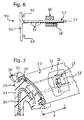
- the motor vehicle 10 shown in Fig. 1 has a door 11 which is provided with a frame 12.
- the frame 12 includes a driven by an electric motor window glass 13, which can be sunk into a window slot of the door 11.
- a sealing and decorative strip is arranged, which serves to seal the window pane 13 and to give the frame 12 an aesthetically pleasing appearance.
- the sealing and decorative strip in the region of the window slot has a seal 20 which is extruded from an elastomeric material, for example EPDM, and seals the window pane 13 along the opening of the window slot.
- a carrier profile performing seal 20 which is reinforced by a metal support 26, a made of metal, for example aluminum, trim strip 30 is attached.
- the one of the seal 20 facing inner surface 31 and a viewer facing outer surface 32 having trim strip 30 is approximately C-shaped in cross section, as shown in particular in FIG. 3 can be seen.
- the trim strip 30 has two hook-shaped edge portions 33 which engage positively and non-positively in recesses 28 of the seal 20, as shown in FIGS. 4 and 7 show.
- the embodiment shown in FIG. 7 additionally has support lips 27 which support the inner surface 31 and generate a clamping force between the trim strip 30 and the seal 20.
- end cap 40 is arranged, which covers a space 41 present between the seal 20 and the inner surface 31 and forms a shapely conclusion for the sealing or decorative strip.
- the made of plastic, for example by injection molding, end cap 40 is composed in a first embodiment of a space 41 covering the cover plate 42 and a mounting member 46 together.
- the cover plate 42 adapted to the contour of the trim strip 30 has an inner side 43 facing the intermediate space 41 and an outer side 44 facing a viewer.
- the in cross-section approximately L-shaped and a first leg 47 and a second leg 51 having fastening member 46 is disposed on the inside 43 and extends into the space 41.
- guide pins 45 are also arranged on the inner surface 31 of Abut decorative strip 30 and support it, as can be seen in Fig. 3.
- the fastening part 46 is latched in the intermediate space 41.
- the first leg 47 has a locking arm 49 formed by a recess 48.
- the locking arm 49 is provided with a projection 50 which engages positively and positively in a recess 20 formed on the seal 20, as shown in FIG. 5 can be seen.
- FIG. 5 furthermore shows that the recess 22 is arranged at a first distance x and the projection 50 is arranged at a second distance y from the inside 43 of the cover plate 42.
- the first distance x is greater than the second distance y with the result that upon engagement of the projection 50 in the recess 22 results in a tensile force F, which the cover plate 42 on the seal 20 and thus on the trim strip 30.
- the second leg 51 is provided with projections 52, which, as shown in FIG. 4 can be seen, are pressed into a sectional surface 29 of the seal 20.
- the projections 52 serve to compensate due to the cutting surface 29 resulting manufacturing tolerances and to ensure a tight fit of the fastening part 46 in the intermediate space 41.
- the end cap 40 has a fastening part 53, which is designed as an elongated sword and provided with a cattle at notches 54.
- the fastening part 53 engages in a locking shoe 55, which is arranged in a form-fitting manner in a groove 23 of the seal 20.
- the groove 23 is provided for this purpose with undercuts 24, which cause a positive connection in a direction perpendicular to the longitudinal direction of the seal 20.
- the locking shoe 55 has for this purpose a bulge 60, which comes to lie in the undercuts 24.
- a positive connection in the longitudinal direction of the groove 23 results from the fact that the locking shoe 55 is arranged in a widening 25, which is located at a predetermined distance z from the inside 43 of the cover plate 42.
- the broadening 25 allows for easy installation and accurate arrangement of the locking shoe 55 in the groove 23. This also contributes that the locking shoe 55 is provided with an extension piece 58 which extends outside the widening 25 in the groove 23, so that the locking shoe 55 is arranged against rotation.
- the locking shoe 55 has an opening 56 into which the fastening part 53 can be inserted.
- the insertion of the attachment part 53 is facilitated by a pointed end portion 59 of the attachment part 53.
- FIGS. 7 and 8 show that in the region of the opening 56 there is arranged a latching edge 57 on which the indentations 54 engage in order to secure the fastening part 53 to the latching shoe 55 in a positive and non-positive manner.
- the end cap 40 can be mounted comparatively easily and reliably fixed to the end portion 21. This is mainly due to that the fastening part 46, 53 is inserted into the intermediate space 41 and locked in this. For the latching of the fastening part 46, the projection 50 of the latching arm 49 engages in the recess 22 of the seal 20. The locking of the fastening part 53, however, results from the interaction of the locking shoe 55 with the notches 54. This attachment of the end cap 40 contributes not least to an aesthetically pleasing appearance by the occurrence of a optical design affecting gap between the cover plate 42 and the trim strip 30 is effectively prevented.
Landscapes
- Engineering & Computer Science (AREA)
- Mechanical Engineering (AREA)
- Seal Device For Vehicle (AREA)
- Sealing Material Composition (AREA)
- Vehicle Interior And Exterior Ornaments, Soundproofing, And Insulation (AREA)
- Motor Or Generator Frames (AREA)
Abstract
Description
- Die Erfindung betrifft einen Dicht- oder Zierstreifen, der insbesondere für Kraftfahrzeuge Anwendung findet. Der Dicht- oder Zierstreifen ist mit einem Trägerprofil versehen, das aus einem elastisch verformbaren Werkstoff gefertigt ist und einen Endabschnitt aufweist. Zudem ist der Dicht- oder Zierstreifen mit einer Zierleiste versehen, die an dem Trägerprofil befestigt ist und eine Innenfläche und eine Aussenfläche aufweist. Eine Endkappe ist an dem Endabschnitt angeordnet und deckt einen zwischen dem Trägerprofil und der Innenfläche vorhandenen Zwischenraum ab.
- Ein Dicht- oder Zierstreifen, der beispielsweise eine Fensterscheibe eines Kraftfahrzeugs einfasst, dient zum einen dazu, die Fensterscheibe abzudichten. Zum anderen hat der Dicht- oder Zierstreifen die Funktion, der Einfassung der Fensterscheibe ein in ästhetischer Hinsicht ansprechendes Erscheinungsbild zu verleihen. Zu diesem Zweck weist der Dicht- oder Zierstreifen eine Zierleiste auf, deren einem Betrachter zugewandte Aussenfläche in der Regel matt oder glänzend ausgestaltet ist und die an einem Trägerprofil befestigt ist. Das Trägerprofil kann Bestandteil einer Dichtung sein, welche die Fensterscheibe abdichtet, wie es aus der WO 2004/056598 A1 bekannt ist.
- Um ein in ästhetischer Hinsicht ansprechendes Erscheinungsbild zu erreichen, ist es ferner bekannt, an einem Endabschnitt des Trägerprofils oder der Zierleiste eine Endkappe anzuordnen, die einen zwischen dem Trägerprofil und der Innenfläche der Zierleiste vorhandenen Zwischenraum abdeckt und auf diese Weise einen formschönen Abschluss bildet. Die üblicherweise aus Kunststoff bestehende Endkappe wird gewöhnlich entweder stoffschlüssig mit dem Trägerprofil verbunden, zum Beispiel mittels Spritzgiessen, oder an die Zierleiste gesteckt. Letzteres erfordert eine spezielle Formgebung der Zierleiste, welche die Gestaltungsfreiheit beschränkt. Zudem ist es im letzteren Fall oftmals erforderlich, die Endkappe zusätzlich zu verkleben oder formschlüssig mit der Zierleiste zu verbinden, um eine zuverlässige Befestigung sicherzustellen.
- Weiterhin offenbart die DT 2 018 864 eine Endkappe, die mit einem Ansatz versehen ist, auf dem die Innenfläche einer Zierleiste aufliegt. Die Endkappe weist darüber hinaus eine Nut, die den Rand der Zierleiste aufnimmt, und federnde Klemmittel, durch welche die Endkappe an einem Flansch befestigbar ist, auf. Die Nut befindet sich in einer geraden Linie mit einer Einlegerille einer Dichtung, die ebenfalls an dem Flansch befestigbar ist. Um die Endkappe zu montieren, ist es erforderlich, zunächst die Dichtung und die Endkappe an dem Flansch zu befestigen und anschliessend die Zierleiste in die Nut und die Einlegerille einzusetzen. Die für die Befestigung der Endkappe dienenden Klemmittel machen es erforderlich, die Endkappe ausserhalb des Bereichs der Dichtung an dem Flansch anzuordnen mit der Folge, dass sich ein vergleichsweise hoher Montageaufwand ergibt.
- Ausserdem wird ein Endstück zum Verschliessen des offenen Endes einer Fahrzeugdichtung in der DE 690 11 936 T2 beschrieben. Das Endstück weist einen C-förmigen Klammerabschnitt auf, der dazu dient, eine Dichtung und eine im Querschnitt L-förmige Ablaufrinne miteinander zu verbinden. Zu diesem Zweck weist der Klammerabschnitt einen oberen Schenkel, der an der Oberseite einer Bodenplatte der Ablaufrinne anliegt und einen unteren Schenkel, der an der Unterseite der Dichtung anliegt, auf. Der obere Schenkel ist auf seiner Oberseite mit einer Nut versehen, in die beim Einführen des Klammerabschnitts in einen von der Dichtung gebildeten Hohlraum ein Vorsprung der Dichtung eingreift, um den Klammerabschnitt zu führen. Beidseitig der Nut sind an der Oberseite des oberen Schenkels zudem Nocken angeordnet, die im eingeschobenen Zustand des Klammerabschnitts an der den Vorsprung umgebenden Innenfläche der Dichtung anliegen. Die Nocken dienen dazu, den Reibschluss zwischen dem oberen Schenkel des Klammerabschnitts und der Dichtung zu erhöhen.
- Der Erfindung liegt die Aufgabe zugrunde, einen Dicht- oder Zierstreifen der eingangs genannten Art dahingehend weiterzubilden, dass sich bei einer vergleichsweise einfachen Montage eine zuverlässige Befestigung der Endkappe erzielen lässt.
- Zur Lösung dieser Aufgabe wird ein Dicht- oder Zierstreifen mit den Merkmalen gemäss Anspruch 1 vorgeschlagen.
- Der erfindungsgemässe Dicht- oder Zierstreifen beruht auf der Erkenntnis, die Endkappe aus einer Abdeckplatte und einem Befestigungsteil zusammenzusetzen, Die zweckmässigerweise an die Kontur der Zierleiste angepasste Abdeckplatte dient vornehmlich dazu, den Zwischenraum zwischen der Zierleiste und dem Trägerprofil abzudecken und damit einen formschönen Abschluss des Dicht- oder Zierstreifens zu bilden. Demgegenüber besteht die Funktion des Befestigungsteils darin, die Endkappe einfach zu montieren und zuverlässig zu befestigen. Zu diesem Zweck weist das Befestigungsteil eine Form auf, die zum einen ein einfaches Einführen des Befestigungsteils in den Zwischenraum und zum anderen ein form- und kraftschlüssiges Festlegen des Befestigungsteils durch Verrasten gewährleistet. Im Unterschied zur Befestigung von herkömmlichen Endkappen macht das Verrasten der Endkappe des erfindungsgemässen Dicht- oder Zierstreifens einen zusätzlichen Stoffschluss entbehrlich, so dass bei einer zuverlässigen Befestigung eine verhältnismässig einfache Montage sichergestellt ist. Darüber hinaus gewährleistet das Verrasten des Befestigungsteils eine präzise Ausrichtung der Endkappe in bezug auf die Zierleiste. Ein das Erscheinungsbild beeinträchtigender Spalt zwischen der Endkappe und der Zierleiste lässt sich auf diese Weise vermeiden.
- Vorteilhafte Ausgestaltungen des erfindungsgemässen Dicht- oder Zierstreifens werden in den Ansprüchen 2 bis 13 definiert.
- Bevorzugt weist die Abdeckplatte eine Innenseite und eine Aussenseite auf. An der Innenseite ist vorzugsweise wenigstens ein Führungsstift angeordnet, der an der Innenfläche der Zierleiste anliegt und diese abstützt, um eine präzise Ausrichtung der Endkappe in bezug auf die Zierleiste zu gewährleisten.
- In diesem Zusammenhang hat es sich als vorteilhaft erwiesen, wenn die Zierleiste im Querschnitt annähernd C-förmig oder V-förmig ist. Denn auf diese Weise lässt sich ein Formschluss zwischen dem Führungsstift und der Zierleiste erreichen, der zu einem dichten Anliegen der Zierleiste an der Endkappe beiträgt.
- In einer bevorzugten Ausführungsform des erfindungsgemässen Dicht- oder Zierstreifens ist das Befestigungsteil im Querschnitt annähernd L-förmig und weist einen ersten Schenkel und einen zweiten Schenkel auf. Der erste Schenkel ist mit einem Rastarm versehen, der einen in eine Aussparung eingreifenden Vorsprung aufweist. Der an dem ersten Schenkel ausgebildete Rastarm hat die Funktion, das Befestigungsteil in dem Zwischenraum zu verrasten. Zu diesem Zweck greift der Vorsprung des Rastarms in die entweder an der Zierleiste oder an dem Trägerprofil ausgebildete Aussparung ein. Der sich im wesentlichen senkrecht zu dem ersten Schenkel erstreckende zweite Schenkel dient vornehmlich dazu, das Befestigungsteil in den Zwischenraum zu führen und ein Widerlager für den Rastarm zu bilden.
- Von besonderem Vorteil ist es, die Aussparung, in die der Vorsprung eingreift, in einem ersten Abstand von der Innenseite der Abdeckplatte und den Vorsprung in einem zweiten Abstand von der Innenseite der Abdeckplatte anzuordnen, wobei der erste Abstand grösser als der zweite Abstand ist. Auf diese Weise lässt sich ein Kraftschluss zwischen dem Vorsprung und der Aussparung erreichen, der eine an dem Befestigungsteil angreifende Zugkraft hervorruft, welche die Endkappe an das Trägerprofil und die Zierleiste heranzieht und damit das Auftreten eines Spalts zwischen der Abdeckplatte und der Zierleiste verhindert.
- Weiterhin ist es von Vorteil, den zweiten Schenkel mit wenigstens einem Vorsprung zu versehen, der in das Trägerprofil eingedrückt ist. Der Vorsprung dient dazu, Fertigungstoleranzen zu kompensieren und einen festen Sitz des Befestigungsteils in dem Zwischenraum zu erreichen. Die Kompensation von Fertigungstoleranzen kommt vor allem dann zum Tragen, wenn das Trägerprofil zur Bildung des Endabschnitts beschnitten wird, so dass der zweite Schenkel an einer Schnittfläche anliegt.
- In einer weiteren bevorzugten Ausführungsform des erfindungsgemässen Dicht- oder Zierstreifens ist an dem Trägerprofil ein Rastschuh angeordnet. Das Befestigungsteil ist in diesem Fall mit einer Vielzahl an Einkerbungen versehen und greift in den Rastschuh derart ein, dass die Einkerbungen des Befestigungsteils form- und kraftschlüssig mit dem Rastschuh verbunden sind. Die Einkerbungen sind zweckmässigerweise in einem relativ geringen Abstand, zum Beispiel 0,5 mm, voneinander beabstandet, um eine möglichst hohe Zugkraft, die durch das Einrasten der Einkerbungen in den Rastschuh hervorgerufen wird, zu erzeugen.
- Das Trägerprofil ist vorteilhafterweise mit einer Nut versehen, wobei der Rastschuh formschlüssig in der Nut angeordnet ist, so dass eine exakte Lage des Rastschuhs gewährleistet ist. Um den Rastschuh formschlüssig in der zweckmässigerweise durch Extrusion des Trägerprofils erzeugten und sich insofern in Längsrichtung des Trägerprofils erstreckenden Nut anzuordnen, kann die Nut mit einer Hinderschneidung versehen sein. Die Hinterschneidung gewährleistet einen Formschluss in einer Richtung senkrecht zur Längsrichtung des Trägerprofils. Um im Bedarfsfall auch einen Formschluss in Längsrichtung des Trägerprofils zu erreichen, kann die Nut in einem vorgegebenen Abstand von der Innenseite der Abdeckplatte mit einer Verbreiterung versehen sein, in welcher der Rastschuh angeordnet ist. Weist die beispielsweise durch Fräsen erzeugte Verbreiterung eine runde Form auf, ist es zudem von Vorteil, den Rastschuh mit einem Ansatzstück zu versehen, das in die Nut eingreift und damit eine verdrehsichere Anordnung des Rastschuhs in der Verbreiterung ermöglicht.
- Die Zierleiste ist zweckmässigerweise aus Kunststoff oder Metall, vorzugsweise Aluminium, gefertigt. Vor allem die Fertigung der Zierleiste aus Aluminium bietet neben einer leichtgewichtigen Ausgestaltung den Vorteil einer in ästhetischer Hinsicht ansprechenden optischen Gestaltung.
- In einer bevorzugten Ausführungsform des erfindungsgemässen Dicht- oder Zierstreifens ist das Trägerprofil als Dichtung ausgestaltet. Um eine einfache und kostengünstige Fertigung zu gewährleisten, ist die Dichtung zweckmässigerweise aus einem elastomeren Werkstoff, vorzugsweise einem thermoplastischen Elastomer (TPE) oder Ethyten-Propyten-Dien-Kautschuk (EPDM), extrudiert. Die Fertigung der Dichtung durch Extrusion trägt der vor allem im Kraftfahrzeugbau anzutreffenden Massenproduktion Rechnung.
- Einzelheiten und weitere Vorteile des erfindungsgemässen Dicht- oder Zierstreifens ergeben sich aus der nachfolgenden Beschreibung zweier bevorzugter Ausführungsbeispiele. In den die Ausführungsbeispiele lediglich schematisch darstellenden Zeichnungen veranschaulichen im einzelnen:
- Fig. 1
- eine Seitenansicht eines Kraftfahrzeugs;
- Fig. 2
- eine perspektivische Ansicht einer Endkappe in einer ersten Ausführungsform des erfindungsgemässen Dicht- oder Zierstreifens;
- Fig. 3
- einen Querschnitt durch eine Zierleiste;
- Fig. 4
- einen Schnitt gemäss der Linie IV in Fig. 1;
- Fig. 5
- einen Längsschnitt durch die Endkappe gemäss Fig. 2;
- Fig. 6
- eine teilgeschnittene Seitenansicht einer Endkappe in einer zweiten Ausführungsform des erfindungsgemässen Dicht- oder Zierstreifens;
- Fig. 7
- einen Schnitt gemäss der Linie VII in Fig. 1 und
- Fig. 8
- einen Querschnitt durch einen in eine Nut einzusetzenden Rastschuh,
- Das in Fig. 1 dargestellte Kraftfahrzeug 10 weist eine Tür 11 auf, die mit einem Rahmen 12 versehen ist. Der Rahmen 12 fasst eine durch einen Elektromotor angetriebene Fensterscheibe 13 ein, die sich in einen Fensterschacht der Tür 11 versenken lässt. Entlang des Rahmens 12 ist ein Dicht- und Zierstreifen angeordnet, der dazu dient, die Fensterscheibe 13 abzudichten und dem Rahmen 12 ein in ästhetischer Hinsicht ansprechendes Erscheinungsbild zu verleihen. Wie insbesondere die Fig. 4 und 7 zu erkennen geben, weist der Dicht- und Zierstreifen im Bereich des Fensterschachts eine Dichtung 20 auf, die aus einem elastomeren Werkstoff, zum Beispiel EPDM, extrudiert ist und die Fensterscheibe 13 entlang der Öffnung des Fensterschachts abdichtet. An der ein Trägerprofil darstellenden Dichtung 20, die durch einen metallenen Träger 26 armiert wird, ist eine aus Metall, zum Beispiel Aluminium, gefertigte Zierleiste 30 befestigt. Die eine der Dichtung 20 zugewandte Innenfläche 31 und eine einem Betrachter zugewandte Aussenfläche 32 aufweisende Zierleiste 30 ist im Querschnitt annähernd C-förmig, wie insbesondere aus Fig. 3 ersichtlich ist. Die Zierleiste 30 weist zwei hakenförmige Randabschnitte 33 auf, die form- und kraftschlüssig in Aussparungen 28 der Dichtung 20 eingreifen, wie die Fig. 4 und 7 zu erkennen geben. Um einen zuverlässigen Kraftschluss zwischen der Zierleiste 30 und der Dichtung 20 zu gewährleisten, weist die in Fig. 7 gezeigte Ausführungsform zusätzlich Stützlippen 27 auf, welche die Innenfläche 31 abstützten und eine Spannkraft zwischen der Zierleiste 30 und der Dichtung 20 erzeugen.
- An einem Endabschnitt 21 der Dichtung 20 ist eine Endkappe 40 angeordnet, die einen zwischen der Dichtung 20 und der Innenfläche 31 vorhandenen Zwischenraum 41 abdeckt und einen formschönen Abschluss für den Dicht- oder Zierstreifen bildet. Die aus Kunststoff, beispielsweise durch Spritzgiessen, gefertigte Endkappe 40 setzt sich in einer ersten Ausführungsform aus einer den Zwischenraum 41 abdeckenden Abdeckplatte 42 und einem Befestigungsteil 46 zusammen.
- Die an die Kontur der Zierleiste 30 angepasste Abdeckplatte 42 weist eine dem Zwischenraum 41 zugewandte Innenseite 43 und eine einem Betrachter zugewandte Aussenseite 44 auf. Das im Querschnitt annähernd L-förmige und einen ersten Schenkel 47 und einen zweiten Schenkel 51 aufweisende Befestigungsteil 46 ist an der Innenseite 43 angeordnet und erstreckt sich in den Zwischenraum 41. An der Innenseite 43 sind ausserdem Führungsstifte 45 angeordnet, die an der Innenfläche 31 der Zierleiste 30 anliegen und diese abstützen, wie in Fig. 3 zu erkennen ist.
- Das Befestigungsteil 46 ist in dem Zwischenraum 41 verrastet. Zu diesem Zweck weist der erste Schenkel 47 einen durch eine Aussparung 48 gebildeten Rastarm 49 auf. Der Rastarm 49 ist mit einem Vorsprung 50 versehen, der in eine an der Dichtung 20 ausgebildete Aussparung 22 kraft- und formschlüssig eingreift, wie aus Fig. 5 ersichtlich ist. Fig. 5 gibt ferner zu erkennen, dass die Aussparung 22 in einem ersten Abstand x und der Vorsprung 50 in einem zweiten Abstand y von der Innenseite 43 der Abdeckplatte 42 angeordnet sind. Der erste Abstand x ist größer als der zweite Abstand y mit der Folge, dass sich beim Eingreifen des Vorsprungs 50 in die Aussparung 22 eine Zugkraft F ergibt, welche die Abdeckplatte 42 an die Dichtung 20 und damit an die Zierleiste 30 heranzieht. Auf diese Weise wird verhindert, dass zwischen der Abdeckplatte 42 und der Zierleiste 30 ein das optische Erscheinungsbild beeinträchtigender Spalt auftritt. Weiterhin ist der zweite Schenkel 51 mit Vorsprüngen 52 versehen, die, wie aus Fig. 4 ersichtlich ist, in eine Schnittfläche 29 der Dichtung 20 eingedrückt sind. Die Vorsprünge 52 dienen dazu, sich aufgrund der Schnittfläche 29 ergebende Fertigungstoleranzen zu kompensieren und einen festen Sitz des Befestigungsteils 46 in dem Zwischenraum 41 zu gewährleisten.
- Bei der in den Fig. 6 bis 8 gezeigten zweiten Ausführungsform weist die Endkappe 40 ein Befestigungsteil 53 auf, das als längliches Schwert ausgestaltet und mit einer Viehahl an Einkerbungen 54 versehen ist. Das Befestigungsteil 53 greift in einen Rastschuh 55 ein, der in einer Nut 23 der Dichtung 20 formschlüssig angeordnet ist. Wie insbesondere Fig. 8 zu erkennen gibt, ist die Nut 23 zu diesem Zweck mit Hinterschneidungen 24 versehen, die einen Formschluss in einer Richtung senkrecht zur Längsrichtung der Dichtung 20 bewirken. Der Rastschuh 55 weist hierfür eine Ausbauchung 60 auf, die in den Hinterschneidungen 24 zu liegen kommt. Ein Formschluss in Längsrichtung der Nut 23 ergibt sich dadurch, dass der Rastschuh 55 in einer Verbreiterung 25 angeordnet ist, die sich in einem vorgegebenen Abstand z von der Innenseite 43 der Abdeckplatte 42 befindet. Die Verbreiterung 25 ermöglicht eine einfache Montage und genaue Anordnung des Rastschuhs 55 in der Nut 23. Hierzu trägt auch bei, dass der Rastschuh 55 mit einem Ansatzstück 58 versehen ist, das sich ausserhalb der Verbreiterung 25 in der Nut 23 erstreckt, so dass der Rastschuh 55 verdrehsicher angeordnet ist.
- Wie insbesondere aus Fig. 8 ersichtlich ist, weist der Rastschuh 55 eine Öffnung 56 auf, in die sich das Befestigungsteil 53 einführen lässt. Das Einführen des Befestigungsteils 53 wird durch einen spitzen Endabschnitt 59 des Befestigungsteils 53 erleichtert. Die Fig. 7 und 8 geben zu erkennen, dass im Bereich der Öffnung 56 eine Rastkante 57 angeordnet ist, an der die Einkerbungen 54 einrasten, um das Befestigungsteil 53 form- und kraftschlüssig an dem Rastschuh 55 zu befestigen.
- Die zuvor beschriebenen Ausführungsformen haben gemein, dass sich die Endkappe 40 vergleichsweise einfach montieren und zuverlässig an dem Endabschnitt 21 befestigen lässt. Dies ist vor allem darauf zurückzuführen, dass das Befestigungsteil 46, 53 in den Zwischenraum 41 eingeführt und in diesem verrastet wird. Für die Verrastung des Befestigungsteils 46 greift der Vorsprung 50 des Rastarms 49 in die Aussparung 22 der Dichtung 20 ein. Die Verrastung des Befestigungsteils 53 hingegen ergibt sich durch das Zusammenwirken des Rastschuhs 55 mit den Einkerbungen 54. Diese Befestigung der Endkappe 40 trägt nicht zuletzt zu einem in ästhetischer Hinsicht ansprechenden Erscheinungsbild bei, indem das Auftreten eines die optische Gestaltung beeinträchtigenden Spalts zwischen der Abdeckplatte 42 und der Zierleiste 30 wirksam verhindert wird.
-
- 10
- Kraftfahrzeug
- 11
- Tür
- 12
- Rahmen
- 13
- Fensterscheibe
- 20
- Dichtung
- 21
- Endabschnitt
- 22
- Aussparung
- 23
- Nut
- 24
- Hinterschneidung
- 25
- Verbreiterung
- 26
- Träger
- 27
- Stützlippe
- 28
- Aussparung
- 29
- Schnittfläche
- 30
- Zierleiste
- 31
- Innenfläche
- 32
- Aussenfläche
- 33
- Randabschnitt
- 40
- Endkappe
- 41
- Zwischenraum
- 42
- Abdeckplatte
- 43
- Innenseite
- 44
- Aussenseite
- 45
- Führungsstift
- 46
- Befestigungsteil
- 47
- erster Schenkel
- 48
- Aussparung
- 49
- Rastarm
- 50
- Vorsprung
- 51
- zweiter Schenkel
- 52
- Vorsprung
- 53
- Befestigungsteil
- 54
- Einkerbung
- 55
- Rastschuh
- 56
- Öffnung
- 57
- Rastkante
- 58
- Ansatzstück
- 59
- spitzer Endabschnitt
- 60
- Ausbauchung
- F
- Zugkraft
- x
- Abstand
- y
- Abstand
- z
- Abstand
Claims (13)
- Dicht- oder Zierstreifen, insbesondere für Kraftfahrzeuge (10), mit
einem Trägerprofil (20), das aus einem elastisch verformbaren Werkstoff gefertigt ist und einen Endabschnitt (21) aufweist,
einer Zierleiste (30), die an dem Trägerprofil (20) befestigt ist und eine Innenfläche (31) und eine Aussenfläche (32) aufweist, und
einer Endkappe (40), die an dem Endabschnitt (21) angeordnet ist und einen zwischen dem Trägerprofil (20) und der Innenfläche (31) vorhandenen Zwischenraum (41) abdeckt,
wobei die Endkappe (40) eine Abdeckplatte (42), die den Zwischenraum (41) abdeckt, und ein Befestigungsteil (46, 53), das sich in den Zwischenraum (41) erstreckt, aufweist und
wobei das Befestigungsteil (46, 53) in dem Zwischenraum (41) verrastet ist. - Dicht- oder Zierstreifen nach Anspruch 1, dadurch gekennzeichnet, dass die Abdeckplatte (42) eine Innenseite (43) und eine Aussenseite (44) aufweist, wobei vorzugsweise an der Innenseite (43) wenigstens ein Führungsstift (45) angeordnet ist, der die Innenfläche (31) der Zierleiste (30) abstützt.
- Dicht- oder Zierstreifen nach Anspruch 1 oder 2, dadurch gekennzeichnet, dass die Zierleiste (30) im Querschnitt annährend C-förmig oder V-förmig ist.
- Dicht- oder Zierstreifen nach einem der Ansprüche 1 bis 3, dadurch gekennzeichnet, dass das Befestigungsteil (46) im Querschnitt annährend L-förmig ist und einen ersten Schenkel (47) und einen zweiten Schenkel (51) aufweist, wobei der erste Schenkel (47) mit einem Rastarm (49) versehen ist, der einen in eine Aussparung (22) eingreifenden Vorsprung (50) aufweist.
- Dicht- oder Zierstreifen nach Anspruch 4, dadurch gekennzeichnet, dass die Aussparung (22) in einem ersten Abstand (x) von der Innenseite (43) der Abdeckplatte (42) und der Vorsprung (50) in einem zweiten Abstand (y) von der Innenseite (43) der Abdeckplatte (42) angeordnet ist, wobei der erste Abstand (x) grösser als der zweite Abstand (y) ist.
- Dicht- oder Zierstreifen nach Anspruch 4 oder 5, dadurch gekennzeichnet, dass der zweite Schenkel (51) mit wenigstens einem Vorsprung (52) versehen ist, der in das Trägerprofil (20) eingedrückt ist.
- Dicht- oder Zierstreifen nach einem der Ansprüche 1 bis 3, dadurch gekennzeichnet, dass an dem Trägerprofil (20) ein Rastschuh (55) angeordnet ist, wobei das Befestigungsteil (53) mit einer Vielzahl an Einkerbungen (54) versehen ist und in den Rastschuh (55) eingreift.
- Dicht- oder Zierstreifen nach Anspruch 7, dadurch gekennzeichnet, dass das Trägerprofil (20) mit einer Nut (23) versehen ist, wobei der Rastschuh (55) formschlüssig in der Nut (23) angeordnet ist.
- Dicht- oder Zierstreifen nach Anspruch 8, dadurch gekennzeichnet, dass die Nut (23) mit einer Hinterscheidung (24) versehen ist.
- Dicht- oder Zierstreifen nach Anspruch 8 oder 9, dadurch gekennzeichnet, dass die Nut (23) in einem vorgegebenen Abstand (z) von der Innenseite (43) der Abdeckplatte (42) mit einer Verbreiterung (25) versehen ist, in welcher der Rastschuh (55) angeordnet ist.
- Dicht- oder Zierstreifen nach Anspruch 10, dadurch gekennzeichnet, dass der Rastschuh (55) mit einem Ansatzstück (58) versehen ist.
- Dicht- oder Zierstreifen nach einem der Ansprüche 1 bis 11, dadurch gekennzeichnet, dass die Zierleiste (30) aus Kunststoff oder Metall, vorzugsweise Aluminium, gefertigt ist.
- Dicht- oder Zierstreifen nach einem der Ansprüche 1 bis 12, dadurch gekennzeichnet, dass das Trägerprofil als Dichtung (20) ausgestaltet ist.
Priority Applications (1)
| Application Number | Priority Date | Filing Date | Title |
|---|---|---|---|
| PL05109023T PL1652710T3 (pl) | 2004-10-27 | 2005-09-29 | Listwa uszczelniająca albo listwa ozdobna, w szczególności do samochodów |
Applications Claiming Priority (1)
| Application Number | Priority Date | Filing Date | Title |
|---|---|---|---|
| DE102004052237A DE102004052237B4 (de) | 2004-10-27 | 2004-10-27 | Dichtstreifen für Kraftfahrzeuge |
Publications (3)
| Publication Number | Publication Date |
|---|---|
| EP1652710A2 true EP1652710A2 (de) | 2006-05-03 |
| EP1652710A3 EP1652710A3 (de) | 2007-11-21 |
| EP1652710B1 EP1652710B1 (de) | 2009-08-19 |
Family
ID=35614556
Family Applications (1)
| Application Number | Title | Priority Date | Filing Date |
|---|---|---|---|
| EP05109023A Not-in-force EP1652710B1 (de) | 2004-10-27 | 2005-09-29 | Dicht- oder Zierstreifen, insbesondere für Kraftfahrzeuge |
Country Status (4)
| Country | Link |
|---|---|
| EP (1) | EP1652710B1 (de) |
| AT (1) | ATE439999T1 (de) |
| DE (2) | DE102004052237B4 (de) |
| PL (1) | PL1652710T3 (de) |
Cited By (8)
| Publication number | Priority date | Publication date | Assignee | Title |
|---|---|---|---|---|
| GB2443319A (en) * | 2006-10-24 | 2008-04-30 | Nippon Pop Rivets And Fastners | Molding and end cap mounting structure |
| FR2959173A1 (fr) * | 2010-04-27 | 2011-10-28 | Peugeot Citroen Automobiles Sa | Ensemble comprenant un lecheur exterieur de vitre et un enjoliveur pourvus de moyens d'indexation et vehicule automobile equipe de tels ensembles. |
| CN102632796A (zh) * | 2011-02-14 | 2012-08-15 | 白木工业株式会社 | 模制件 |
| US8493081B2 (en) | 2009-12-08 | 2013-07-23 | Magna Closures Inc. | Wide activation angle pinch sensor section and sensor hook-on attachment principle |
| US9234979B2 (en) | 2009-12-08 | 2016-01-12 | Magna Closures Inc. | Wide activation angle pinch sensor section |
| WO2021256201A1 (ja) * | 2020-06-18 | 2021-12-23 | シロキ工業株式会社 | 車両用モール及び車両用モールの組み立て方法 |
| JP7468180B2 (ja) | 2020-06-18 | 2024-04-16 | 株式会社アイシン | 車両用モール及び車両用モールの組み立て方法 |
| JP7480603B2 (ja) | 2020-06-18 | 2024-05-10 | 株式会社アイシン | 車両用モール及び車両用モールの組み立て方法 |
Families Citing this family (4)
| Publication number | Priority date | Publication date | Assignee | Title |
|---|---|---|---|---|
| DE102007045678A1 (de) * | 2007-09-25 | 2009-04-16 | Daimler Ag | Anordnung mit einem Rohbauteil eines Fahrzeugs und einem daran anbringbaren Designelement |
| DE102009016258A1 (de) * | 2009-04-03 | 2010-10-14 | GM Global Technology Operations, Inc., Detroit | Zierblendenanordnung für Kraftfahrzeuge |
| DE202011051037U1 (de) * | 2011-08-19 | 2012-11-27 | Rehau Ag + Co. | Zierleiste, insbesondere Fensterschachtabdeckung für ein Kraftfahrzeug |
| CN103568797B (zh) | 2012-08-01 | 2017-04-12 | 亨尼格斯汽车密封系统北美公司 | 用于密封配件的双端帽 |
Citations (5)
| Publication number | Priority date | Publication date | Assignee | Title |
|---|---|---|---|---|
| DE2018864A1 (de) * | 1970-04-14 | 1971-11-25 | Draftex Gmbh | Halterung für Zierleisten an mit einem Gummi- oder Kunststoff-Dichtungsstreifen versehenen Rahmen von Türen oder Fenstern |
| EP0482999A1 (de) * | 1990-10-25 | 1992-04-29 | Hutchinson | Ansatzstück für Profilteil zum Beispiel Dichtungsprofil für Fahrzeugschiebefenster |
| EP0395444B1 (de) * | 1989-04-28 | 1994-08-31 | Kinugawa Rubber Industrial Co., Ltd. | Endstück zum Verschliessen des offenen Endes einer Fahrzeugdichtung |
| WO1998040234A2 (en) * | 1997-02-28 | 1998-09-17 | Gerard Francis Robinson | Receptacle seal |
| JPH1134757A (ja) * | 1997-07-23 | 1999-02-09 | Toyoda Gosei Co Ltd | 自動車用モール |
Family Cites Families (4)
| Publication number | Priority date | Publication date | Assignee | Title |
|---|---|---|---|---|
| DE1930493A1 (de) * | 1969-06-16 | 1970-12-23 | Liverpa Gmbh | Profilschiene mit Endstueck |
| DE9006548U1 (de) * | 1990-06-09 | 1990-08-16 | Rehau Ag + Co, 8673 Rehau, De | |
| DE20207098U1 (de) * | 2002-05-04 | 2003-09-18 | Klein Walter Gmbh & Co Kg | Kraftfahrzeug-Zierleiste |
| DE10259843B3 (de) * | 2002-12-19 | 2004-08-26 | Metzeler Automotive Profile Systems Gmbh | Dichtungsanordnung, insbesondere zum Abdichten von Fensterscheiben eines Kraftfahrzeuges |
-
2004
- 2004-10-27 DE DE102004052237A patent/DE102004052237B4/de not_active Expired - Fee Related
-
2005
- 2005-09-29 DE DE502005007919T patent/DE502005007919D1/de active Active
- 2005-09-29 AT AT05109023T patent/ATE439999T1/de not_active IP Right Cessation
- 2005-09-29 PL PL05109023T patent/PL1652710T3/pl unknown
- 2005-09-29 EP EP05109023A patent/EP1652710B1/de not_active Not-in-force
Patent Citations (5)
| Publication number | Priority date | Publication date | Assignee | Title |
|---|---|---|---|---|
| DE2018864A1 (de) * | 1970-04-14 | 1971-11-25 | Draftex Gmbh | Halterung für Zierleisten an mit einem Gummi- oder Kunststoff-Dichtungsstreifen versehenen Rahmen von Türen oder Fenstern |
| EP0395444B1 (de) * | 1989-04-28 | 1994-08-31 | Kinugawa Rubber Industrial Co., Ltd. | Endstück zum Verschliessen des offenen Endes einer Fahrzeugdichtung |
| EP0482999A1 (de) * | 1990-10-25 | 1992-04-29 | Hutchinson | Ansatzstück für Profilteil zum Beispiel Dichtungsprofil für Fahrzeugschiebefenster |
| WO1998040234A2 (en) * | 1997-02-28 | 1998-09-17 | Gerard Francis Robinson | Receptacle seal |
| JPH1134757A (ja) * | 1997-07-23 | 1999-02-09 | Toyoda Gosei Co Ltd | 自動車用モール |
Cited By (12)
| Publication number | Priority date | Publication date | Assignee | Title |
|---|---|---|---|---|
| GB2443319A (en) * | 2006-10-24 | 2008-04-30 | Nippon Pop Rivets And Fastners | Molding and end cap mounting structure |
| US7785686B2 (en) | 2006-10-24 | 2010-08-31 | Newfrey Llc | Molding |
| US8493081B2 (en) | 2009-12-08 | 2013-07-23 | Magna Closures Inc. | Wide activation angle pinch sensor section and sensor hook-on attachment principle |
| US9234979B2 (en) | 2009-12-08 | 2016-01-12 | Magna Closures Inc. | Wide activation angle pinch sensor section |
| US9417099B2 (en) | 2009-12-08 | 2016-08-16 | Magna Closures Inc. | Wide activation angle pinch sensor section |
| FR2959173A1 (fr) * | 2010-04-27 | 2011-10-28 | Peugeot Citroen Automobiles Sa | Ensemble comprenant un lecheur exterieur de vitre et un enjoliveur pourvus de moyens d'indexation et vehicule automobile equipe de tels ensembles. |
| WO2011135220A1 (fr) * | 2010-04-27 | 2011-11-03 | Peugeot Citroën Automobiles SA | Ensemble comprenant un lecheur exterieur de vitre et un enjoliveur pourvus de moyens d'indexation et vehicule automobile equipe de tels ensembles |
| CN102632796A (zh) * | 2011-02-14 | 2012-08-15 | 白木工业株式会社 | 模制件 |
| US8758872B2 (en) | 2011-02-14 | 2014-06-24 | Shiroki Corporation | Edge protector |
| WO2021256201A1 (ja) * | 2020-06-18 | 2021-12-23 | シロキ工業株式会社 | 車両用モール及び車両用モールの組み立て方法 |
| JP7468180B2 (ja) | 2020-06-18 | 2024-04-16 | 株式会社アイシン | 車両用モール及び車両用モールの組み立て方法 |
| JP7480603B2 (ja) | 2020-06-18 | 2024-05-10 | 株式会社アイシン | 車両用モール及び車両用モールの組み立て方法 |
Also Published As
| Publication number | Publication date |
|---|---|
| EP1652710B1 (de) | 2009-08-19 |
| PL1652710T3 (pl) | 2010-01-29 |
| ATE439999T1 (de) | 2009-09-15 |
| DE502005007919D1 (de) | 2009-10-01 |
| EP1652710A3 (de) | 2007-11-21 |
| DE102004052237A1 (de) | 2006-05-04 |
| DE102004052237B4 (de) | 2008-12-18 |
Similar Documents
| Publication | Publication Date | Title |
|---|---|---|
| EP1652710B1 (de) | Dicht- oder Zierstreifen, insbesondere für Kraftfahrzeuge | |
| DE10259843B3 (de) | Dichtungsanordnung, insbesondere zum Abdichten von Fensterscheiben eines Kraftfahrzeuges | |
| EP1920963B1 (de) | Dichtungsanordnung zum Abdichten von beweglichen KFZ-Fensterscheiben | |
| DE10313601B4 (de) | Dichtungsanordnung zum Abdichten und Führen einer bewegbaren Fensterscheibe, insbesondere eines Kraftfahrzeugs | |
| EP2142394B1 (de) | Führungsanordnung für eine bewegbare fensterscheibe eines kraftfahrzeugs | |
| DE10247015B4 (de) | Dichtungsprofil mit Zierleiste | |
| EP0182318B1 (de) | Vorrichtung zur gleichzeitigen Abdichtung der Türscheibe und des Dachbereiches einer Kraftfahrzeug-Tür | |
| DE60219541T2 (de) | Türzarge für Kraftfahrzeuge | |
| DE20321549U1 (de) | Dicht-, Trimm- oder Führungsleiste | |
| EP2463133B1 (de) | Dichtungsanordnung für eine Scheibeneinheit | |
| EP1131220B1 (de) | Fensterdichtungsprofil für ein kabriolett | |
| DE60320276T9 (de) | Dichtungs-, zier- oder führungsstreifen | |
| DE10134465C1 (de) | Dichtung, insbesondere zum Abdichten einer in einer Kraftfahrzeugtür verschiebbar angeordneten Fensterscheibe | |
| EP1737638B1 (de) | Verfahren zum herstellen eines dicht- oder zierstreifens, insbesondere für ein kraftfahrzeug, sowie ein solcher dicht- oder zierstreifen | |
| EP1500542B1 (de) | Dichtungsanordnung, insbesondere zum Abdichten einer feststehenden Fensterscheibe eines Kraftfahrzeugs | |
| DE102019213427A1 (de) | Fensterführung für eine Fensterscheibe eines Kraftfahrzeugs | |
| DE10233422B4 (de) | Dichtungsanordnung, insbesondere zum Abdichten einer verfahrbaren Fensterscheibe eines Kraftfahrzeugs | |
| EP1737692B1 (de) | Verfahren zum herstellen eines dicht-oder zierstreifens, insbesondere für ein kraftfahrzeug, sowie ein solcher dicht-oder zierstreifen | |
| DE10146628B4 (de) | Dichtungsanordnung zum Abdichten des Fensterschachts eines Kraftfahrzeugs | |
| EP2107976A1 (de) | Dichtung zum abdichten der fensterscheibe eines kraftfahrzeugs, verstärkungsträger für eine solche dichtung und verfahren zum herstellen der dichtung | |
| DE10230682B4 (de) | Dichtungsanordnung zum Abdichten eines Spalts, insbesondere an einem Kraftfahrzeug | |
| DE3824793A1 (de) | Halteelement fuer eine rahmenlose, hoehenverstellbare tuerfensterscheibe | |
| DE102005013507B3 (de) | Dichtungsanordnung, insbesondere zum Abdichten einer Fensterscheibe eines Kraftfahrzeugs | |
| DE102006002466B4 (de) | Dichtungsanordnung, insbesondere zum Abdichten einer Fensterscheibe eines Kraftfahrzeugs | |
| EP0121820A1 (de) | In der Höhe verstellbare Fensterscheibe, insbesondere für Kraftfahrzeuge |
Legal Events
| Date | Code | Title | Description |
|---|---|---|---|
| PUAI | Public reference made under article 153(3) epc to a published international application that has entered the european phase |
Free format text: ORIGINAL CODE: 0009012 |
|
| AK | Designated contracting states |
Kind code of ref document: A2 Designated state(s): AT BE BG CH CY CZ DE DK EE ES FI FR GB GR HU IE IS IT LI LT LU LV MC NL PL PT RO SE SI SK TR |
|
| AX | Request for extension of the european patent |
Extension state: AL BA HR MK YU |
|
| PUAL | Search report despatched |
Free format text: ORIGINAL CODE: 0009013 |
|
| AK | Designated contracting states |
Kind code of ref document: A3 Designated state(s): AT BE BG CH CY CZ DE DK EE ES FI FR GB GR HU IE IS IT LI LT LU LV MC NL PL PT RO SE SI SK TR |
|
| AX | Request for extension of the european patent |
Extension state: AL BA HR MK YU |
|
| RIC1 | Information provided on ipc code assigned before grant |
Ipc: B60J 10/04 20060101AFI20071012BHEP Ipc: B60J 10/00 20060101ALI20071012BHEP |
|
| 17P | Request for examination filed |
Effective date: 20080221 |
|
| 17Q | First examination report despatched |
Effective date: 20080320 |
|
| AKX | Designation fees paid |
Designated state(s): AT BE BG CH CY CZ DE DK EE ES FI FR GB GR HU IE IS IT LI LT LU LV MC NL PL PT RO SE SI SK TR |
|
| GRAP | Despatch of communication of intention to grant a patent |
Free format text: ORIGINAL CODE: EPIDOSNIGR1 |
|
| GRAS | Grant fee paid |
Free format text: ORIGINAL CODE: EPIDOSNIGR3 |
|
| GRAA | (expected) grant |
Free format text: ORIGINAL CODE: 0009210 |
|
| AK | Designated contracting states |
Kind code of ref document: B1 Designated state(s): AT BE BG CH CY CZ DE DK EE ES FI FR GB GR HU IE IS IT LI LT LU LV MC NL PL PT RO SE SI SK TR |
|
| REG | Reference to a national code |
Ref country code: GB Ref legal event code: FG4D Free format text: NOT ENGLISH |
|
| REG | Reference to a national code |
Ref country code: CH Ref legal event code: EP |
|
| REG | Reference to a national code |
Ref country code: IE Ref legal event code: FG4D |
|
| REF | Corresponds to: |
Ref document number: 502005007919 Country of ref document: DE Date of ref document: 20091001 Kind code of ref document: P |
|
| REG | Reference to a national code |
Ref country code: SK Ref legal event code: T3 Ref document number: E 6236 Country of ref document: SK |
|
| LTIE | Lt: invalidation of european patent or patent extension |
Effective date: 20090819 |
|
| PG25 | Lapsed in a contracting state [announced via postgrant information from national office to epo] |
Ref country code: FI Free format text: LAPSE BECAUSE OF FAILURE TO SUBMIT A TRANSLATION OF THE DESCRIPTION OR TO PAY THE FEE WITHIN THE PRESCRIBED TIME-LIMIT Effective date: 20090819 Ref country code: LT Free format text: LAPSE BECAUSE OF FAILURE TO SUBMIT A TRANSLATION OF THE DESCRIPTION OR TO PAY THE FEE WITHIN THE PRESCRIBED TIME-LIMIT Effective date: 20090819 Ref country code: IS Free format text: LAPSE BECAUSE OF FAILURE TO SUBMIT A TRANSLATION OF THE DESCRIPTION OR TO PAY THE FEE WITHIN THE PRESCRIBED TIME-LIMIT Effective date: 20091219 Ref country code: ES Free format text: LAPSE BECAUSE OF FAILURE TO SUBMIT A TRANSLATION OF THE DESCRIPTION OR TO PAY THE FEE WITHIN THE PRESCRIBED TIME-LIMIT Effective date: 20091130 Ref country code: SE Free format text: LAPSE BECAUSE OF FAILURE TO SUBMIT A TRANSLATION OF THE DESCRIPTION OR TO PAY THE FEE WITHIN THE PRESCRIBED TIME-LIMIT Effective date: 20090819 |
|
| REG | Reference to a national code |
Ref country code: PL Ref legal event code: T3 |
|
| NLV1 | Nl: lapsed or annulled due to failure to fulfill the requirements of art. 29p and 29m of the patents act | ||
| PG25 | Lapsed in a contracting state [announced via postgrant information from national office to epo] |
Ref country code: LV Free format text: LAPSE BECAUSE OF FAILURE TO SUBMIT A TRANSLATION OF THE DESCRIPTION OR TO PAY THE FEE WITHIN THE PRESCRIBED TIME-LIMIT Effective date: 20090819 Ref country code: SI Free format text: LAPSE BECAUSE OF FAILURE TO SUBMIT A TRANSLATION OF THE DESCRIPTION OR TO PAY THE FEE WITHIN THE PRESCRIBED TIME-LIMIT Effective date: 20090819 Ref country code: NL Free format text: LAPSE BECAUSE OF FAILURE TO SUBMIT A TRANSLATION OF THE DESCRIPTION OR TO PAY THE FEE WITHIN THE PRESCRIBED TIME-LIMIT Effective date: 20090819 |
|
| BERE | Be: lapsed |
Owner name: METZELER AUTOMOTIVE PROFILE SYSTEMS G.M.B.H. Effective date: 20090930 |
|
| PG25 | Lapsed in a contracting state [announced via postgrant information from national office to epo] |
Ref country code: BG Free format text: LAPSE BECAUSE OF FAILURE TO SUBMIT A TRANSLATION OF THE DESCRIPTION OR TO PAY THE FEE WITHIN THE PRESCRIBED TIME-LIMIT Effective date: 20091119 Ref country code: PT Free format text: LAPSE BECAUSE OF FAILURE TO SUBMIT A TRANSLATION OF THE DESCRIPTION OR TO PAY THE FEE WITHIN THE PRESCRIBED TIME-LIMIT Effective date: 20091221 Ref country code: CY Free format text: LAPSE BECAUSE OF FAILURE TO SUBMIT A TRANSLATION OF THE DESCRIPTION OR TO PAY THE FEE WITHIN THE PRESCRIBED TIME-LIMIT Effective date: 20090819 |
|
| PG25 | Lapsed in a contracting state [announced via postgrant information from national office to epo] |
Ref country code: MC Free format text: LAPSE BECAUSE OF NON-PAYMENT OF DUE FEES Effective date: 20090930 Ref country code: EE Free format text: LAPSE BECAUSE OF FAILURE TO SUBMIT A TRANSLATION OF THE DESCRIPTION OR TO PAY THE FEE WITHIN THE PRESCRIBED TIME-LIMIT Effective date: 20090819 Ref country code: RO Free format text: LAPSE BECAUSE OF FAILURE TO SUBMIT A TRANSLATION OF THE DESCRIPTION OR TO PAY THE FEE WITHIN THE PRESCRIBED TIME-LIMIT Effective date: 20090819 Ref country code: DK Free format text: LAPSE BECAUSE OF FAILURE TO SUBMIT A TRANSLATION OF THE DESCRIPTION OR TO PAY THE FEE WITHIN THE PRESCRIBED TIME-LIMIT Effective date: 20090819 |
|
| REG | Reference to a national code |
Ref country code: CH Ref legal event code: PL |
|
| PLBE | No opposition filed within time limit |
Free format text: ORIGINAL CODE: 0009261 |
|
| STAA | Information on the status of an ep patent application or granted ep patent |
Free format text: STATUS: NO OPPOSITION FILED WITHIN TIME LIMIT |
|
| 26N | No opposition filed |
Effective date: 20100520 |
|
| PG25 | Lapsed in a contracting state [announced via postgrant information from national office to epo] |
Ref country code: BE Free format text: LAPSE BECAUSE OF NON-PAYMENT OF DUE FEES Effective date: 20090930 |
|
| PG25 | Lapsed in a contracting state [announced via postgrant information from national office to epo] |
Ref country code: GR Free format text: LAPSE BECAUSE OF FAILURE TO SUBMIT A TRANSLATION OF THE DESCRIPTION OR TO PAY THE FEE WITHIN THE PRESCRIBED TIME-LIMIT Effective date: 20091120 Ref country code: CH Free format text: LAPSE BECAUSE OF NON-PAYMENT OF DUE FEES Effective date: 20090930 Ref country code: LI Free format text: LAPSE BECAUSE OF NON-PAYMENT OF DUE FEES Effective date: 20090930 |
|
| PG25 | Lapsed in a contracting state [announced via postgrant information from national office to epo] |
Ref country code: AT Free format text: LAPSE BECAUSE OF NON-PAYMENT OF DUE FEES Effective date: 20090929 |
|
| PG25 | Lapsed in a contracting state [announced via postgrant information from national office to epo] |
Ref country code: IT Free format text: LAPSE BECAUSE OF FAILURE TO SUBMIT A TRANSLATION OF THE DESCRIPTION OR TO PAY THE FEE WITHIN THE PRESCRIBED TIME-LIMIT Effective date: 20090819 |
|
| PG25 | Lapsed in a contracting state [announced via postgrant information from national office to epo] |
Ref country code: LU Free format text: LAPSE BECAUSE OF NON-PAYMENT OF DUE FEES Effective date: 20090929 |
|
| PG25 | Lapsed in a contracting state [announced via postgrant information from national office to epo] |
Ref country code: HU Free format text: LAPSE BECAUSE OF FAILURE TO SUBMIT A TRANSLATION OF THE DESCRIPTION OR TO PAY THE FEE WITHIN THE PRESCRIBED TIME-LIMIT Effective date: 20100220 |
|
| REG | Reference to a national code |
Ref country code: DE Ref legal event code: R008 Ref document number: 502005007919 Country of ref document: DE |
|
| REG | Reference to a national code |
Ref country code: DE Ref legal event code: R082 Ref document number: 502005007919 Country of ref document: DE Representative=s name: FLUEGEL PREISSNER KASTEL SCHOBER, DE |
|
| REG | Reference to a national code |
Ref country code: DE Ref legal event code: R082 Ref document number: 502005007919 Country of ref document: DE Representative=s name: FLUEGEL PREISSNER KASTEL SCHOBER, DE Effective date: 20131118 Ref country code: DE Ref legal event code: R081 Ref document number: 502005007919 Country of ref document: DE Owner name: COOPER STANDARD GMBH, DE Free format text: FORMER OWNER: METZELER AUTOMOTIVE PROFILE SYSTEMS GMBH, 88131 LINDAU, DE Effective date: 20131118 Ref country code: DE Ref legal event code: R082 Ref document number: 502005007919 Country of ref document: DE Representative=s name: FLUEGEL PREISSNER KASTEL SCHOBER PATENTANWAELT, DE Effective date: 20131118 Ref country code: DE Ref legal event code: R082 Ref document number: 502005007919 Country of ref document: DE Representative=s name: FLUEGEL PREISSNER SCHOBER SEIDEL PATENTANWAELT, DE Effective date: 20131118 |
|
| REG | Reference to a national code |
Ref country code: DE Ref legal event code: R039 Ref document number: 502005007919 Country of ref document: DE Effective date: 20131030 |
|
| REG | Reference to a national code |
Ref country code: SK Ref legal event code: TC4A Ref document number: E 6236 Country of ref document: SK Owner name: COOPER STANDARD GMBH, LINDAU/BODENSEE, DE Effective date: 20141212 |
|
| REG | Reference to a national code |
Ref country code: DE Ref legal event code: R040 Ref document number: 502005007919 Country of ref document: DE Ref country code: DE Ref legal event code: R097 Ref document number: 502005007919 Country of ref document: DE |
|
| REG | Reference to a national code |
Ref country code: FR Ref legal event code: PLFP Year of fee payment: 12 |
|
| REG | Reference to a national code |
Ref country code: FR Ref legal event code: PLFP Year of fee payment: 13 |
|
| REG | Reference to a national code |
Ref country code: FR Ref legal event code: CD Owner name: COOPER STANDARD GMBH, DE Effective date: 20170831 |
|
| PGFP | Annual fee paid to national office [announced via postgrant information from national office to epo] |
Ref country code: SK Payment date: 20170919 Year of fee payment: 13 Ref country code: CZ Payment date: 20170918 Year of fee payment: 13 |
|
| PGFP | Annual fee paid to national office [announced via postgrant information from national office to epo] |
Ref country code: PL Payment date: 20170918 Year of fee payment: 13 Ref country code: IE Payment date: 20170921 Year of fee payment: 13 Ref country code: TR Payment date: 20170920 Year of fee payment: 13 |
|
| REG | Reference to a national code |
Ref country code: FR Ref legal event code: PLFP Year of fee payment: 14 |
|
| PG25 | Lapsed in a contracting state [announced via postgrant information from national office to epo] |
Ref country code: CZ Free format text: LAPSE BECAUSE OF NON-PAYMENT OF DUE FEES Effective date: 20180929 |
|
| REG | Reference to a national code |
Ref country code: SK Ref legal event code: MM4A Ref document number: E 6236 Country of ref document: SK Effective date: 20180929 |
|
| REG | Reference to a national code |
Ref country code: IE Ref legal event code: MM4A |
|
| PG25 | Lapsed in a contracting state [announced via postgrant information from national office to epo] |
Ref country code: IE Free format text: LAPSE BECAUSE OF NON-PAYMENT OF DUE FEES Effective date: 20180929 |
|
| PG25 | Lapsed in a contracting state [announced via postgrant information from national office to epo] |
Ref country code: SK Free format text: LAPSE BECAUSE OF NON-PAYMENT OF DUE FEES Effective date: 20180929 |
|
| PG25 | Lapsed in a contracting state [announced via postgrant information from national office to epo] |
Ref country code: PL Free format text: LAPSE BECAUSE OF NON-PAYMENT OF DUE FEES Effective date: 20180929 |
|
| PGFP | Annual fee paid to national office [announced via postgrant information from national office to epo] |
Ref country code: FR Payment date: 20210927 Year of fee payment: 17 |
|
| PGFP | Annual fee paid to national office [announced via postgrant information from national office to epo] |
Ref country code: GB Payment date: 20210923 Year of fee payment: 17 Ref country code: DE Payment date: 20210929 Year of fee payment: 17 |
|
| PG25 | Lapsed in a contracting state [announced via postgrant information from national office to epo] |
Ref country code: TR Free format text: LAPSE BECAUSE OF NON-PAYMENT OF DUE FEES Effective date: 20180929 |
|
| REG | Reference to a national code |
Ref country code: DE Ref legal event code: R119 Ref document number: 502005007919 Country of ref document: DE |
|
| GBPC | Gb: european patent ceased through non-payment of renewal fee |
Effective date: 20220929 |
|
| PG25 | Lapsed in a contracting state [announced via postgrant information from national office to epo] |
Ref country code: FR Free format text: LAPSE BECAUSE OF NON-PAYMENT OF DUE FEES Effective date: 20220930 Ref country code: DE Free format text: LAPSE BECAUSE OF NON-PAYMENT OF DUE FEES Effective date: 20230401 |
|
| PG25 | Lapsed in a contracting state [announced via postgrant information from national office to epo] |
Ref country code: GB Free format text: LAPSE BECAUSE OF NON-PAYMENT OF DUE FEES Effective date: 20220929 |