EP1652589A2 - Dispositif de mélange et de distribution comprenant deux récipients - Google Patents
Dispositif de mélange et de distribution comprenant deux récipients Download PDFInfo
- Publication number
- EP1652589A2 EP1652589A2 EP05021471A EP05021471A EP1652589A2 EP 1652589 A2 EP1652589 A2 EP 1652589A2 EP 05021471 A EP05021471 A EP 05021471A EP 05021471 A EP05021471 A EP 05021471A EP 1652589 A2 EP1652589 A2 EP 1652589A2
- Authority
- EP
- European Patent Office
- Prior art keywords
- container
- containers
- valve
- components
- mixing
- Prior art date
- Legal status (The legal status is an assumption and is not a legal conclusion. Google has not performed a legal analysis and makes no representation as to the accuracy of the status listed.)
- Withdrawn
Links
Images


Classifications
-
- B—PERFORMING OPERATIONS; TRANSPORTING
- B05—SPRAYING OR ATOMISING IN GENERAL; APPLYING FLUENT MATERIALS TO SURFACES, IN GENERAL
- B05C—APPARATUS FOR APPLYING FLUENT MATERIALS TO SURFACES, IN GENERAL
- B05C17/00—Hand tools or apparatus using hand held tools, for applying liquids or other fluent materials to, for spreading applied liquids or other fluent materials on, or for partially removing applied liquids or other fluent materials from, surfaces
- B05C17/005—Hand tools or apparatus using hand held tools, for applying liquids or other fluent materials to, for spreading applied liquids or other fluent materials on, or for partially removing applied liquids or other fluent materials from, surfaces for discharging material from a reservoir or container located in or on the hand tool through an outlet orifice by pressure without using surface contacting members like pads or brushes
- B05C17/00503—Details of the outlet element
- B05C17/00516—Shape or geometry of the outlet orifice or the outlet element
-
- B—PERFORMING OPERATIONS; TRANSPORTING
- B05—SPRAYING OR ATOMISING IN GENERAL; APPLYING FLUENT MATERIALS TO SURFACES, IN GENERAL
- B05C—APPARATUS FOR APPLYING FLUENT MATERIALS TO SURFACES, IN GENERAL
- B05C17/00—Hand tools or apparatus using hand held tools, for applying liquids or other fluent materials to, for spreading applied liquids or other fluent materials on, or for partially removing applied liquids or other fluent materials from, surfaces
- B05C17/005—Hand tools or apparatus using hand held tools, for applying liquids or other fluent materials to, for spreading applied liquids or other fluent materials on, or for partially removing applied liquids or other fluent materials from, surfaces for discharging material from a reservoir or container located in or on the hand tool through an outlet orifice by pressure without using surface contacting members like pads or brushes
- B05C17/00553—Hand tools or apparatus using hand held tools, for applying liquids or other fluent materials to, for spreading applied liquids or other fluent materials on, or for partially removing applied liquids or other fluent materials from, surfaces for discharging material from a reservoir or container located in or on the hand tool through an outlet orifice by pressure without using surface contacting members like pads or brushes with means allowing the stock of material to consist of at least two different components
- B05C17/00556—Hand tools or apparatus using hand held tools, for applying liquids or other fluent materials to, for spreading applied liquids or other fluent materials on, or for partially removing applied liquids or other fluent materials from, surfaces for discharging material from a reservoir or container located in or on the hand tool through an outlet orifice by pressure without using surface contacting members like pads or brushes with means allowing the stock of material to consist of at least two different components with means for adjusting the proportions of the components
Definitions
- the present invention relates to an apparatus for mixing two different components.
- Two-component systems in which two different components are purposefully mixed together, are well known.
- reactive adhesives and sealants can be used in a wide variety of applications.
- two-component systems for casting and encapsulating in the field of electrical engineering can be used.
- a known mixing device is designed as a 2-K mixing gun in which the materials to be mixed are provided in two cartridges. About one piston, the material from the cartridges is pressed into a tubular or syringe-shaped mixer.
- a latching mechanism is provided which causes a gradual advancement of the pistons in the cartridges. It is also known to provide a pneumatic feed of the piston instead of the mechanical locking mechanism.
- the invention has for its object to provide a device for mixing two different components, which allows easy handling and controlled discharge of the components to be mixed.
- the device according to the invention serves to mix two different components, which preferably react with each other to obtain the desired material. It has two containers, each containing a component, connecting means to which the components are supplied separately from the container and from which they emerge, for example, to be brought into contact with each other in a mixer. Further, an actuator is provided which triggers the entry of the components in a predetermined ratio from the containers in the connection means.
- a pressurized container is provided as a container from which the components are discharged via a valve by means of a propellant. In the apparatus according to the invention, the valves of the container are opened and closed via the actuating device.
- a piston in the cartridge is no longer moved directly by the actuating device, but a valve of a pressurized container is opened.
- the components then exit via the valve from the pressure vessel and are supplied to the connection means and / or forwarded to a mixer.
- a particular advantage of the device according to the invention is that the components to be mixed are provided in pressurized containers at which the discharge of the components to be mixed is effected by a propellant in the container.
- a dispenser container having a substantially cylindrical shape is provided as the container.
- the dispenser containers can be arranged as a package parallel to one another, wherein the containers are preferably each provided with a valve on the front side.
- At least one of the containers is provided with a male valve which opens by pressure in the axial direction on a protruding stem and / or opens by tilting the protruding Stems transversely to the axial direction.
- at least one of the containers is provided with a female valve which opens to pressure in the axial direction.
- connection means on a mixing body with two inlet openings and two channels.
- a check valve is preferably provided in each case in the channel, which prevents a backflow of the components to the container.
- the connecting means further have an insert body which forms the channels together with the mixing body.
- the connection means are preferably provided with a mixer tube, in which the components are then mixed with each other. Conveniently, the mixer tube is placed on the mixing body.
- the device according to the invention has a holding part for detachable connection with the containers.
- the containers may be replaced individually or in pairs for use on the holding member.
- the holding part is equipped with a handle and an operating lever.
- the actuating lever is articulated to the holding part and has a cooperating with the containers projection.
- the holding part further preferably has a head portion in which the connection means are arranged.
- the containers can be arranged together in a receiving sleeve, wherein the sleeve has locking means which engage behind a projection of the container.
- the latching means comprise a latching plate with two recesses, wherein additionally a lever may be provided to release the latching plate from its latched position.
- the receiving sleeve further has a contact surface, which cooperates with the actuating device.
- the sleeve can be moved together with the containers in the head portion of the holder to open the valves of the container. The force is transmitted via the connecting means on the valve.
- each container attachment has two holders, which receive the container in the head or foot area.
- At least one of the container attachments has an opening in the region of the receptacle through which the valve of the container is accessible.
- the stem protrudes through the opening.
- a neck nozzle or the like can pass through the aperture and actuate the valve in the container cap.
- locking projections are preferably provided, which engage behind corresponding projections on the containers.
- the container attachment for the head region of the containers has a stop surface which cooperates with the actuating device. Upon actuation of the container attachment is advanced together with the containers and the force used for this is implemented to open the container valves.
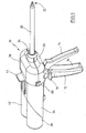
- the mixing gun 10 has a handle 12 with an actuating lever 14.
- the handle 12 has a receptacle 16 which receives the actuating lever 14 in the depressed state. Further, the handle 12 is laterally provided with a projection 18 which can serve as an abutment for the thumb during actuation.
- the 2-K mixing gun has a mixer 20 having internally known helical mixing plates in it to mix the two components advancing.
- the mixed components exit at the mixer tip 22.
- the mixer 20 is selected with its diameter and the arrangement of the baffles used in a conventional manner according to the requirements of the components to be mixed.
- the mixer 20 is screwed with a union nut 24 to a holder 26.
- the holder 26 has a head portion 28 having an upper half 30 and a lower half 32 which is connected to the handle 12.
- the holder 26 further has a support plate 34, through which the actuating lever 14 protrudes (see Figure 3). Upper and lower parts of the head portion 28 may be bolted together.
- the illustrated two-component mixing gun also has a sleeve-like container receptacle 36 which accommodates two cylindrical dispensing containers 38, 40.
- the container receptacle 36 has at its end facing the mixer 20, a detent plate 42 which is fixed to a movable tongue 46 of the holder 36 and can be moved by a protruding lever 44 (see Figure 3).
- dispenser containers 38 and 40 are inserted in the axial direction in the receptacle 36 and advanced so far until the detent plate 42 engages behind the valve plate, the edge of the container or another projection on the dispenser containers.
- the containers are then connected to the container receptacle 36.
- the lever 44 is deflected away from the mixer 20 to release the cans 38 and 40.
- connection means are provided in the head region.
- the illustrated connection means consists of a mixer body 46 which has two inlet openings 48, 50 for the valves of the containers 38 and 40.
- mixing of the components takes place first in the mixer and not yet in the mixer body.
- the inlet openings point in the direction of the mixer tube 20.
- the inlet channel 52 and 54 adjoining the inlet openings 48 and 50 has a check valve 56 and 58.
- the check valve 56 and 58 is inserted into the mixer body via a lateral opening.
- the check valves are tapered membrane elements which have a slot which is opened in the direction of passage through the medium and compressed in the opposite direction.
- a channel body 60 Centrally between the channels 52 and 54, a channel body 60 is set, which forms an extension of the two channels 52 and 54 towards the mixer.
- the insert body 60 has a partition wall 62 which extends through the channel.
- the insert body 60 may for example be held on the side facing away from the mixer side of the mixing body 46 with projections.
- the channel body 60 also serves as an attachment for the mixer 20.
- the container receptacle 36 has on its underside a groove 64 which opens into a stop surface 66 on the side facing the mixer.
- the operating lever 14 has a bore 70, by the actuating lever 14 is pivotally mounted with a pin 68 on the handle 12.
- a projection 72 protrudes into the holder and bears against the stop surface 66.
- the receptacle 36 is moved toward the mixer via the projection 72 and the stop surface 66.
- the containers 38 and 40 are pressed with the protruding stem of the valves 74 and 78 in the receptacles 48 and 50.
- the valves of the containers 38 and 40 open and the components exit under pressure and enter the mixer 20.
- a second detent plate which corresponds in geometry substantially the detent plate 42 and this is arranged opposite in the container receptacle 36.
- This allows the dispenser containers 38 and 40 to be held in the container receptacle 36 for application of the corresponding force.
- this can be biased by a leaf spring 80 in the latched position.
- the leaf spring 80 is guided by rails 82 and 84 on the receptacle 36.
- the force is applied directly from the operating lever to the container receptacle for the dispensing container.
- the container receptacle for the dispensing container To strengthen the power, it is also possible to provide here even a conversion or a transmission.
- the 2-component mixing gun is preferably made of a reinforced plastic and designed for permanent use. Depending on the valve used, a different stroke must be provided. For standard valves, a stroke of two to three millimeters is usually sufficient. In addition to the illustrated axial-operated valves and tilt valves can be used. The design of the valves may vary, for example, so-called bag-on-valve valves or valves with an internal, pressure-guided piston can be used.
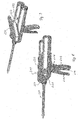
- FIG. 6 shows two can-shaped containers 160 and 162, each having a protruding stem 164, 166.
- the valve cooperating with the stem may be a valve as used for PU foam.
- the containers 60 and 62 are held in parallel and in the same orientation relative to one another via a pair of container attachments 168 and 170.
- Each container attachment has an approximately bony shape, each with a receptacle for the container.
- the substantially circular receptacles for the container ends are connected to each other via a bridge section.
- the bridge sections have cross-shaped webs 172, 174.
- the provided in the head region of the container container cap 168 has a provided on the side facing away from the valves side stop surface for an actuator. Conveniently, this stop surface can be approximately at the height of the longitudinal axis of the container 160, 162, so that tilting of the container is avoided during advancement.
- a latching mechanism is preferably used for connecting the container attachments 168 and 170 with the containers 160 and 162.
- the container attachments are renewed together with the containers. This can be achieved by appropriate profiling of the container tops and the holder a VerleychScience.
- the container top 168 is slidably guided in the head portion 128 of the holder, the container receptacle 136 is not required in this case.
- a spring-loaded release lever can be provided, which engages behind the bridge section.
- a solvent is provided, which dissolves the container attachment in the head part of the holder, so that the container attachment can be removed.
- the two dispenser containers are already connected together to form a package.
- a suitable receptacle or a suitable mixing body that the containers are used reversed.
- dispensing containers with different volumes and different valves may be provided.
- the locking means engage behind this preferred.
- FIGS. 8 and 9 show an alternative embodiment of a two-component mixing gun 210.
- the mixing gun has like the model already described a handle 212, with a receptacle 216 for the actuating lever 214. Also, a projection 18 is provided as a shelf for the thumb again.
- the mixer 220 is fastened to a holder 226 via a union nut 224, just as in the known model.
- the holder 226 consists of a lower half-shell 228 and an upper half-shell 230.
- the lower half-shell 228 is connected to the handle 212 and has an opening on the side facing the handle, through which a projection 272 of the actuating lever 214 protruding into the interior.
- the upper half shell 230 may be secured to the lower half shell 228 via two pairs of screws which are guided by screw channels 229 in the lower half shell 228.
- a cover element 231 is provided, which engages via lateral latching edges 233 and a latching projection 235 both with the upper half-shell 230 and with the lower half-shell 228.
- the cover 231 has at the rear end, centrally, a projection 237 with a detent 239. The projection 237 is performed between the containers 238 and 240 and secures the cover 231 in addition to the lower half-shell 228th
- the two containers 238 and 240 are received in a pair of container attachments 268 and 270.
- the front container attachment 268 is connected to both containers 238 and 240.
- the container cap 268 has an annular Recess with locking means, which engage with a circumferential projection along the valve plate.
- the container adapter 268 has on its underside a recess into which the projection 272 of the actuating lever 214 protrudes. In use, the actuating lever 214 is pressed and the applied force is transmitted to the upper container adapter. The containers 238 and 240 together with the lower container attachment 270 are thus moved towards the mixer 220.
- the protruding stem of the valves projects through the container cap 268 into a mixer body 246 which serves as an attachment for the mixer.
- the components to be mixed are fed separately through the mixer body to the mixer.
- FIG. 11 shows a cross section through the front section of the mixing gun.
- the mixer body 246 has two separate channels 252 and 254.
- the stems 248 and 250 are inserted in the mixer body 246.
- valves so-called tilt valves are shown in Figure 11, which also open to pressure in the axial direction.
Applications Claiming Priority (1)
| Application Number | Priority Date | Filing Date | Title |
|---|---|---|---|
| DE102004052986A DE102004052986A1 (de) | 2004-11-02 | 2004-11-02 | Vorrichtung zum Mischen von zwei unterschiedlichen Komponenten |
Publications (2)
| Publication Number | Publication Date |
|---|---|
| EP1652589A2 true EP1652589A2 (fr) | 2006-05-03 |
| EP1652589A3 EP1652589A3 (fr) | 2008-01-23 |
Family
ID=35482267
Family Applications (1)
| Application Number | Title | Priority Date | Filing Date |
|---|---|---|---|
| EP05021471A Withdrawn EP1652589A3 (fr) | 2004-11-02 | 2005-09-30 | Dispositif de mélange et de distribution comprenant deux récipients |
Country Status (4)
| Country | Link |
|---|---|
| US (1) | US7481332B2 (fr) |
| EP (1) | EP1652589A3 (fr) |
| CA (1) | CA2525005C (fr) |
| DE (1) | DE102004052986A1 (fr) |
Cited By (3)
| Publication number | Priority date | Publication date | Assignee | Title |
|---|---|---|---|---|
| EP2781253A1 (fr) * | 2013-03-20 | 2014-09-24 | Sulzer Mixpac AG | Pièce intermédiaire destinée à relier un élément d'extraction à un réservoir |
| EP3574989A1 (fr) * | 2018-05-29 | 2019-12-04 | Soudal | Système de distribution de mélange de deux composants et buse de mélange statique |
| RU2777389C2 (ru) * | 2018-05-29 | 2022-08-02 | Судаль | Система дозирования для смеси двух компонентов и статическая смесительная насадка для нее |
Families Citing this family (36)
| Publication number | Priority date | Publication date | Assignee | Title |
|---|---|---|---|---|
| US8512718B2 (en) | 2000-07-03 | 2013-08-20 | Foamix Ltd. | Pharmaceutical composition for topical application |
| IL152486A0 (en) | 2002-10-25 | 2003-05-29 | Meir Eini | Alcohol-free cosmetic and pharmaceutical foam carrier |
| WO2004037225A2 (fr) | 2002-10-25 | 2004-05-06 | Foamix Ltd. | Mousse cosmetique et pharmaceutique |
| US10117812B2 (en) | 2002-10-25 | 2018-11-06 | Foamix Pharmaceuticals Ltd. | Foamable composition combining a polar solvent and a hydrophobic carrier |
| US8900554B2 (en) | 2002-10-25 | 2014-12-02 | Foamix Pharmaceuticals Ltd. | Foamable composition and uses thereof |
| US9211259B2 (en) | 2002-11-29 | 2015-12-15 | Foamix Pharmaceuticals Ltd. | Antibiotic kit and composition and uses thereof |
| US9668972B2 (en) | 2002-10-25 | 2017-06-06 | Foamix Pharmaceuticals Ltd. | Nonsteroidal immunomodulating kit and composition and uses thereof |
| US20080138296A1 (en) | 2002-10-25 | 2008-06-12 | Foamix Ltd. | Foam prepared from nanoemulsions and uses |
| US8486376B2 (en) | 2002-10-25 | 2013-07-16 | Foamix Ltd. | Moisturizing foam containing lanolin |
| US7704518B2 (en) | 2003-08-04 | 2010-04-27 | Foamix, Ltd. | Foamable vehicle and pharmaceutical compositions thereof |
| US9265725B2 (en) | 2002-10-25 | 2016-02-23 | Foamix Pharmaceuticals Ltd. | Dicarboxylic acid foamable vehicle and pharmaceutical compositions thereof |
| US7700076B2 (en) | 2002-10-25 | 2010-04-20 | Foamix, Ltd. | Penetrating pharmaceutical foam |
| US7820145B2 (en) | 2003-08-04 | 2010-10-26 | Foamix Ltd. | Oleaginous pharmaceutical and cosmetic foam |
| US7575739B2 (en) | 2003-04-28 | 2009-08-18 | Foamix Ltd. | Foamable iodine composition |
| US8486374B2 (en) | 2003-08-04 | 2013-07-16 | Foamix Ltd. | Hydrophilic, non-aqueous pharmaceutical carriers and compositions and uses |
| US8795693B2 (en) | 2003-08-04 | 2014-08-05 | Foamix Ltd. | Compositions with modulating agents |
| US20070069046A1 (en) * | 2005-04-19 | 2007-03-29 | Foamix Ltd. | Apparatus and method for releasing a measure of content from a plurality of containers |
| US20080260655A1 (en) | 2006-11-14 | 2008-10-23 | Dov Tamarkin | Substantially non-aqueous foamable petrolatum based pharmaceutical and cosmetic compositions and their uses |
| US8636982B2 (en) | 2007-08-07 | 2014-01-28 | Foamix Ltd. | Wax foamable vehicle and pharmaceutical compositions thereof |
| WO2009056991A2 (fr) * | 2007-09-04 | 2009-05-07 | Foamix Ltd. | Dispositif de distribution d'une composition expansible |
| US9439857B2 (en) | 2007-11-30 | 2016-09-13 | Foamix Pharmaceuticals Ltd. | Foam containing benzoyl peroxide |
| US8518376B2 (en) | 2007-12-07 | 2013-08-27 | Foamix Ltd. | Oil-based foamable carriers and formulations |
| WO2009090495A2 (fr) | 2007-12-07 | 2009-07-23 | Foamix Ltd. | Vecteurs moussants siliconés à base d'huile et de liquide, et formulations |
| EP2242476A2 (fr) | 2008-01-14 | 2010-10-27 | Foamix Ltd. | Compositions pharmaceutiques pouvant mousser de poloxamère avec des agents actifs et/ou des cellules thérapeutiques, et utilisations |
| WO2010125470A2 (fr) | 2009-04-28 | 2010-11-04 | Foamix Ltd. | Véhicule moussant et compositions pharmaceutiques comportant des solvants polaires aprotiques et leurs utilisations |
| CA2769677A1 (fr) | 2009-07-29 | 2011-02-03 | Foamix Ltd. | Compositions hydro-alcooliques moussantes a base d'agents non tensioactifs non polymeres, mousses legeres, et leurs utilisations |
| CA2769625C (fr) | 2009-07-29 | 2017-04-11 | Foamix Ltd. | Compositions hydro-alcooliques moussantes non tensioactives, mousses legeres, et leurs utilisations |
| CN102686205A (zh) | 2009-10-02 | 2012-09-19 | 弗艾米克斯有限公司 | 局部四环素组合物 |
| US9849142B2 (en) | 2009-10-02 | 2017-12-26 | Foamix Pharmaceuticals Ltd. | Methods for accelerated return of skin integrity and for the treatment of impetigo |
| US8978936B2 (en) | 2010-07-12 | 2015-03-17 | Foamix Pharmaceuticals Ltd. | Apparatus and method for releasing a unit dose of content from a container |
| US9085002B2 (en) * | 2011-05-19 | 2015-07-21 | Illinois Tool Works Inc. | Modular manifold adhesive gun |
| US9655479B2 (en) * | 2013-01-15 | 2017-05-23 | Gojo Industries, Inc. | Two-liquid dispensing systems, refills and two-liquid pumps |
| JP2019509951A (ja) * | 2016-03-16 | 2019-04-11 | ヘンケル・アクチェンゲゼルシャフト・ウント・コムパニー・コマンディットゲゼルシャフト・アウフ・アクチェンHenkel AG & Co. KGaA | 1成分および2成分のホイルおよびカートリッジ用のバッテリー駆動式ディスペンサ |
| US10398641B2 (en) | 2016-09-08 | 2019-09-03 | Foamix Pharmaceuticals Ltd. | Compositions and methods for treating rosacea and acne |
| EP3299082A1 (fr) * | 2016-09-21 | 2018-03-28 | 3M Innovative Properties Company | Ensemble mélangeur et dispositif de distribution de matériau dentaire |
| DE202021002842U1 (de) | 2021-09-02 | 2022-01-19 | IAB-Institut für Angewandte Bauforschung Weimar gemeinnützige GmbH | Vorrichtung zur schonenden Homogenisierung zweier getrennt erzeugter Schäume zu einem Schaum |
Citations (6)
| Publication number | Priority date | Publication date | Assignee | Title |
|---|---|---|---|---|
| US1892649A (en) * | 1930-05-15 | 1932-12-27 | Hills Mccanna Co | Check valve |
| US3303970A (en) | 1964-07-14 | 1967-02-14 | Jerome Marrow | Device for simultaneously dispensing from plural sources |
| WO1999036345A2 (fr) | 1998-01-16 | 1999-07-22 | Flexible Products Company | Dispositif de distribution avec fixation de recipient unique |
| DE10009233A1 (de) | 1999-02-26 | 2000-08-31 | Wella Ag | Druckgasbehältervorrichtung |
| JP2003034374A (ja) | 2001-07-25 | 2003-02-04 | Yoshida Industry Co Ltd | 二剤混合吐出容器 |
| GB2395526A (en) | 2002-09-13 | 2004-05-26 | Bissell Homecare Inc | Manual spray cleaner |
Family Cites Families (7)
| Publication number | Priority date | Publication date | Assignee | Title |
|---|---|---|---|---|
| US3575319A (en) * | 1968-07-11 | 1971-04-20 | Upjohn Co | Portable dispenser for polymer foams |
| US4880143A (en) * | 1988-10-20 | 1989-11-14 | Insta-Foam Products | Dispenser and components for high viscosity foam products |
| JPH1086982A (ja) * | 1996-09-11 | 1998-04-07 | Yoshino Kogyosho Co Ltd | エアゾール式二液混合噴出器 |
| DE19743957A1 (de) * | 1997-10-04 | 1999-07-08 | Dbs Gmbh | Verfahren zur Herstellung von Formkörpern und Flächenabdeckungen und Anlage |
| US6691898B2 (en) * | 2002-02-27 | 2004-02-17 | Fomo Products, Inc. | Push button foam dispensing device |
| AU2003249301A1 (en) * | 2002-07-16 | 2004-02-02 | Mixtek System, Llc | Aerosol mixing system with columns |
| EP1426306A1 (fr) * | 2002-12-06 | 2004-06-09 | The Procter & Gamble Company | Dispositif de mélange et de distribution comprenant deux récipients sous pression |
-
2004
- 2004-11-02 DE DE102004052986A patent/DE102004052986A1/de not_active Withdrawn
-
2005
- 2005-09-30 EP EP05021471A patent/EP1652589A3/fr not_active Withdrawn
- 2005-11-01 US US11/265,263 patent/US7481332B2/en not_active Expired - Fee Related
- 2005-11-01 CA CA002525005A patent/CA2525005C/fr not_active Expired - Fee Related
Patent Citations (6)
| Publication number | Priority date | Publication date | Assignee | Title |
|---|---|---|---|---|
| US1892649A (en) * | 1930-05-15 | 1932-12-27 | Hills Mccanna Co | Check valve |
| US3303970A (en) | 1964-07-14 | 1967-02-14 | Jerome Marrow | Device for simultaneously dispensing from plural sources |
| WO1999036345A2 (fr) | 1998-01-16 | 1999-07-22 | Flexible Products Company | Dispositif de distribution avec fixation de recipient unique |
| DE10009233A1 (de) | 1999-02-26 | 2000-08-31 | Wella Ag | Druckgasbehältervorrichtung |
| JP2003034374A (ja) | 2001-07-25 | 2003-02-04 | Yoshida Industry Co Ltd | 二剤混合吐出容器 |
| GB2395526A (en) | 2002-09-13 | 2004-05-26 | Bissell Homecare Inc | Manual spray cleaner |
Cited By (8)
| Publication number | Priority date | Publication date | Assignee | Title |
|---|---|---|---|---|
| EP2781253A1 (fr) * | 2013-03-20 | 2014-09-24 | Sulzer Mixpac AG | Pièce intermédiaire destinée à relier un élément d'extraction à un réservoir |
| WO2014146967A1 (fr) * | 2013-03-20 | 2014-09-25 | Sulzer Mixpac Ag | Pièce intermédiaire pour la liaison d'un élément de distribution à un récipient de stockage |
| US9718089B2 (en) | 2013-03-20 | 2017-08-01 | Sulzer Mixpac Ag | Intermediate piece for the connection of a dispensing element to a storage container |
| EP3574989A1 (fr) * | 2018-05-29 | 2019-12-04 | Soudal | Système de distribution de mélange de deux composants et buse de mélange statique |
| WO2019228693A1 (fr) * | 2018-05-29 | 2019-12-05 | Soudal | Système de distribution pour le mélange de deux composants et buse de mélange statique associée |
| BE1026292B1 (nl) * | 2018-05-29 | 2020-04-21 | Soudal Nv | Doseersysteem voor het mengen van twee componenten en statisch mengmondstuk daarvoor |
| CN112423870A (zh) * | 2018-05-29 | 2021-02-26 | 速的奥公司 | 用于两种组分的混合的分配系统及用于其的静态混合管嘴 |
| RU2777389C2 (ru) * | 2018-05-29 | 2022-08-02 | Судаль | Система дозирования для смеси двух компонентов и статическая смесительная насадка для нее |
Also Published As
| Publication number | Publication date |
|---|---|
| CA2525005C (fr) | 2009-10-27 |
| US20060114745A1 (en) | 2006-06-01 |
| EP1652589A3 (fr) | 2008-01-23 |
| DE102004052986A1 (de) | 2006-05-04 |
| US7481332B2 (en) | 2009-01-27 |
| CA2525005A1 (fr) | 2006-05-02 |
Similar Documents
| Publication | Publication Date | Title |
|---|---|---|
| EP1652589A2 (fr) | Dispositif de mélange et de distribution comprenant deux récipients | |
| EP0287043B1 (fr) | Pistolet pour produit à composants multiples | |
| DE1457440C3 (de) | Vorrichtung zum Abgeben eines Gemisches aus zwei treibmittelbeaufschlagten flüssigen Komponenten | |
| EP0252401B1 (fr) | Appareil distributeur à cartouches | |
| EP2134475B1 (fr) | Dispositif pour pulvériser des liquides pigmentés | |
| EP2605858B1 (fr) | Module de distribution et procédé pour remplir un module de distribution | |
| EP3094414B1 (fr) | Dispositif de distribution | |
| DE2437647A1 (de) | Spritzpistole fuer reaktionsfaehige gemische | |
| DE10114624B4 (de) | Druckdose und ihre Verwendung für 2-Komponentensysteme | |
| EP1806184A2 (fr) | Cartouche pour dispositif de décharge | |
| EP2292337B1 (fr) | Pistolet calfeutreur | |
| EP1516679B1 (fr) | Dispositif d'extrusion avec un dispositif de dosage | |
| DE1929844A1 (de) | Geraet zum Abgeben von Verbrauchsstoffen,z.B. Rasierkrem | |
| EP0621083A1 (fr) | Dispositif pour vider des cartouches | |
| WO2010145889A1 (fr) | Cartouche à plusieurs constituants à usage unique | |
| DE3802519C2 (de) | Vorrichtung zur dosierten Abgabe von flüssigen oder fließfähigen, miteinander unter Bildung einer nichtfließfähigen Masse chemisch reagierenden Materialkomponenten | |
| EP2062821A1 (fr) | Dispositif de remplissage d'un récipient avec un liquide | |
| EP1481734B1 (fr) | Fermeture par une tête de pulvérisation | |
| WO2004056281A1 (fr) | Dispositif servant a distribuer un melange de plusieurs composants | |
| DE102010060671B4 (de) | Integrierter Radialer Zapfenverschluss für Mehrkomponentenkartuschen mit Mischer | |
| DE102014116585B4 (de) | Spritzvorrichtung und System mit einer Spritzvorrichtung und einer Kartusche | |
| CH674949A5 (en) | Dispenser and mixer for reaction multicomponent substance | |
| CH694690A5 (de) | Auspressvorrichtung für pastöse Massen. | |
| DE8515861U1 (de) | Auffüllvorrichtung für mit einem Sprühventil versehene dosenförmige Behälter | |
| DE4001528A1 (de) | Spender fuer pastoese materialien |
Legal Events
| Date | Code | Title | Description |
|---|---|---|---|
| PUAI | Public reference made under article 153(3) epc to a published international application that has entered the european phase |
Free format text: ORIGINAL CODE: 0009012 |
|
| AK | Designated contracting states |
Kind code of ref document: A2 Designated state(s): AT BE BG CH CY CZ DE DK EE ES FI FR GB GR HU IE IS IT LI LT LU LV MC NL PL PT RO SE SI SK TR |
|
| AX | Request for extension of the european patent |
Extension state: AL BA HR MK YU |
|
| PUAL | Search report despatched |
Free format text: ORIGINAL CODE: 0009013 |
|
| AK | Designated contracting states |
Kind code of ref document: A3 Designated state(s): AT BE BG CH CY CZ DE DK EE ES FI FR GB GR HU IE IS IT LI LT LU LV MC NL PL PT RO SE SI SK TR |
|
| AX | Request for extension of the european patent |
Extension state: AL BA HR MK YU |
|
| 17P | Request for examination filed |
Effective date: 20080405 |
|
| 17Q | First examination report despatched |
Effective date: 20080509 |
|
| AKX | Designation fees paid |
Designated state(s): AT BE BG CH CY CZ DE DK EE ES FI FR GB GR HU IE IS IT LI LT LU LV MC NL PL PT RO SE SI SK TR |
|
| STAA | Information on the status of an ep patent application or granted ep patent |
Free format text: STATUS: THE APPLICATION IS DEEMED TO BE WITHDRAWN |
|
| 18D | Application deemed to be withdrawn |
Effective date: 20101012 |