EP2062821A1 - Dispositif de remplissage d'un récipient avec un liquide - Google Patents
Dispositif de remplissage d'un récipient avec un liquide Download PDFInfo
- Publication number
- EP2062821A1 EP2062821A1 EP08020516A EP08020516A EP2062821A1 EP 2062821 A1 EP2062821 A1 EP 2062821A1 EP 08020516 A EP08020516 A EP 08020516A EP 08020516 A EP08020516 A EP 08020516A EP 2062821 A1 EP2062821 A1 EP 2062821A1
- Authority
- EP
- European Patent Office
- Prior art keywords
- container
- piston
- inner container
- fluid
- pressure
- Prior art date
- Legal status (The legal status is an assumption and is not a legal conclusion. Google has not performed a legal analysis and makes no representation as to the accuracy of the status listed.)
- Withdrawn
Links
Images


Classifications
-
- B—PERFORMING OPERATIONS; TRANSPORTING
- B65—CONVEYING; PACKING; STORING; HANDLING THIN OR FILAMENTARY MATERIAL
- B65B—MACHINES, APPARATUS OR DEVICES FOR, OR METHODS OF, PACKAGING ARTICLES OR MATERIALS; UNPACKING
- B65B3/00—Packaging plastic material, semiliquids, liquids or mixed solids and liquids, in individual containers or receptacles, e.g. bags, sacks, boxes, cartons, cans, or jars
- B65B3/04—Methods of, or means for, filling the material into the containers or receptacles
- B65B3/10—Methods of, or means for, filling the material into the containers or receptacles by application of pressure to material
- B65B3/12—Methods of, or means for, filling the material into the containers or receptacles by application of pressure to material mechanically, e.g. by pistons or pumps
-
- B—PERFORMING OPERATIONS; TRANSPORTING
- B65—CONVEYING; PACKING; STORING; HANDLING THIN OR FILAMENTARY MATERIAL
- B65B—MACHINES, APPARATUS OR DEVICES FOR, OR METHODS OF, PACKAGING ARTICLES OR MATERIALS; UNPACKING
- B65B31/00—Packaging articles or materials under special atmospheric or gaseous conditions; Adding propellants to aerosol containers
Definitions
- the invention relates to a device for filling a container, in particular a pressure vessel, with a fluid, preferably a paint, colorant or other substance used in the surface coating.
- Various containers can be filled and / or filled with such a device with a fluid, in particular an aerosol.
- a fluid in particular an aerosol.
- Such containers are used to suitably deploy a fluid held therein for each purpose, which may be useful in particular for the coating of any surfaces or body.
- the container is for this purpose mostly under pressure, wherein the fluid is discharged from the container through a container opening, which may be integrated, for example, in a valve to be actuated by means of a spray head, in particular sprayed.
- the present invention is therefore based on the object to design a device of the type mentioned and further, that can be filled with this container in a comfortable and easy way, but at the same time the previously necessary cleaning of the device - for example in a color change of the fluid - largely eliminated. Furthermore, a safe operation of the device should be ensured.
- the above object is achieved by the features of claim 1.
- the device in question is characterized by a pressure-resistant outer container and in the outer container preferably positively fitting inner container comprehensive pressure means for pushing the fluid into the container, wherein the inner container for receiving the fluid and excludes an immediate contact of the fluid to the outer container.
- the outer container is primarily the function to record the occurring during filling, possibly high pressure.
- the pressure is absorbed in a technically favorable manner by the inner container is adapted in terms of its shape to the outer container, namely in these fits.
- a particularly secure and pressure-stable recording of the inner container in the outer container can be achieved if it is a form-fitting fit. Due to the fit, the outer container absorbs the pressure arising in the inner container uniformly and is expediently dimensioned in accordance with the expected forces.
- the inner container has the function of receiving the fluid and of excluding direct contact of the fluid with the outer container.
- the inner container which is in direct contact with the fluid, is therefore preferably designed as an easily exchangeable component, which can be exchanged in a simple manner if necessary, for example a color change.
- the user may therefore have various inner containers (“inlets”) available for different shades or grades of fluids for use in the outer container.
- the device can be operated easily and safely.
- the inner container can be inexpensively, for example, thin-walled and / or made of an easy-to-process material and thus designed as a disposable part.
- the costs saved by the respective cleaning outweigh the production costs of the inner container.
- the user therefore continues to save money.
- the outer container and / or the inner container has or have a substantially cylindrical basic shape.
- a cylindrical basic shape initially offers the advantage that even with small wall thickness relatively large pressure forces can be absorbed.
- such a design with many materials can be realized inexpensively.
- the outer container and the inner container are formed in a particularly advantageous development substantially cylindrical. The preferred positive fit of inner and outer container can be realized particularly favorable.
- the printing device is designed such that the inner container can be inserted into the outer container.
- This can be achieved by the outer container having an opening for introducing the inner container.
- the two containers - as described in the previous paragraph - shaped substantially cylindrical can be created in a particularly simple manner, a positive fit of the container into each other.
- the mutually facing wall surfaces of the outer and inner containers are largely in contact with each other.
- the forces acting on the inner container pressure forces are then passed directly to the pressure-resistant outer container, which can easily accommodate these due to suitable choice of material and / or appropriate design - and thus sufficient strength.
- it is ensured that the inner container even at high internal pressure is protected against severe deformation, but at the same time - when pressure relief - a simple and thus comfortable replacement of the inner container is possible.
- the outer container and the inner container each have at least one outlet opening.
- an outlet opening of the inner container may be arranged such that it is in coincidence with an outlet opening of the outer container. Fluid exiting the inner container can thus easily escape from the pressure device without coming into contact with the outer container.
- a favorable development of the device provides that a coupling section is formed on the outer container, which serves to connect the container.
- This coupling portion could preferably be in the vicinity of the outlet opening.
- a coupling section ensures that the container is fixed to the device during filling, in order to ensure the necessary tightness and reliability despite the prevailing pressure.
- the coupling portion on the outer container expediently has a largely complementary shape to a coupling portion designed as a container, so that, for example, by means of positive and / or frictional connection in a simple and fast way, a connection can be made. In the simplest case, a plug-in connection, screw or the like.
- the coupling portion extends circumferentially around the outlet opening of the outer container. Due to the circumferential course of the coupling portion can - with appropriate design - a tube-like connection to the container are created, whereby a mechanically favorable all-sided hold and simple sealing options are given.
- Means for sealing and / or locking the container relative to the outer container may be provided on the coupling portion, wherein generally customary measures may be used.
- a lock with a simultaneous sealing effect can be achieved in a constructively favorable manner if a groove for a sealing ring, spring ring and / or the like is formed on the coupling portion of the outer container is.
- Such a groove could preferably be formed on the outside circumference, wherein a spring ring arranged in the annular groove thus formed is achieved by cooperating with a groove or recess complementary to the container, ie inside the groove, to lock and seal the connection.
- an outlet pipe for discharging the fluid is arranged at the outlet opening of the inner container.
- the outlet tube may be connected to the inner container cohesively or in any other way, resulting in a preferred integral design with the inner container in terms of strength and tightness special advantages.
- the primary purpose of the outlet pipe is to ensure, in the region of the outlet opening, that contact between the fluid and the outer container is excluded when the container is being filled.
- the outlet tube therefore directs the fluid from the inner container directly to a filling region of the container.
- a check valve or the like can be arranged on the outlet pipe.
- the container to be filled already has an internal pressure above atmospheric pressure. Therefore, in the spray head such containers usually a valve is arranged.
- this valve for further filling of the container, it is necessary to actuate this valve, which in an advantageous development of the device can be ensured by the fact that an end of the outlet tube facing away from the inner container protrudes into a region of the container.
- a valve provided on the container could be actuated.
- the end of the outlet tube which thus faces the container, accordingly expediently has a length and shape which triggers a valve actuation when the container is connected to the device.
- the end of the outlet tube then encounters, for example, a valve lug, whereby the flow channel is released.
- the end may be pointed and used for piercing a surface or for other purposes.
- the outlet tube should make as tight a connection as possible to the container.
- this can be realized favorably by forming a contact area for engagement with a filling opening on the container at the outlet pipe. When filling the container, this contact area is then at the filling opening of the container, which could, for example.
- additional contact pressure achieve a desired sealing effect.
- the contact region may favor the connection of the container to the device, if this is at least partially conically shaped.
- the used for printing device advantageously on a cylinder-piston assembly.
- a piston is assigned to the inner container, is generated by the stroke of the necessary pressure for delivering the fluid.
- the actuation of the piston can take place in different ways, for example mechanically, electromechanically, hydraulically and / or pneumatically, wherein the drive is preferably realized by a stamp connected to the piston.
- the cylinder-piston arrangement could generate the pressure on the fluid in principle by piston pressure or Kolbenyak.
- the outlet opening of the inner container is formed on the cylinder head. To allow easy insertion of the piston in the inner container, the inner container on the cylinder base on an insertion opening for the piston. This insertion opening could - with the piston removed - continue to be used to fill the inner container.
- a suitable seal should be provided between the moving piston and the inner container serving as a cylinder.
- This can be, for example, realized by appropriately sized piston rings, but can also be achieved in a particularly advantageous manner by the fact that the piston relative to the inner container has a certain excess. Is or are the piston and / or the inner container made of a corresponding elastic material, so occurs upon insertion of the piston in the Inner container on one or both of these components to a slight elastic deformation, resulting in a mutual contact pressure with an advantageous sealing effect.
- the outer surface of the piston peripherally adjacent to the inner container has a profiling in the circumferential direction, preferably a V-profile, U-profile, W-profile or the like.
- the piston in principle, regardless of the choice of material, but especially in a production of plastic, it makes sense to form the piston as a hollow part with a closed piston head, which may be formed to stiffen the piston in this radially extending reinforcing struts.
- a version as a hollow part saves material and weight.
- the inner container and / or the piston is made of plastic, preferably by injection molding.
- Plastics for example polypropylene, have the advantage of being able to be brought into complicated shapes in a simple manner, have sufficient elasticity and can be produced inexpensively in large quantities, in particular by injection molding.
- the inner container must be worked precisely to ensure its function. On the one hand, this relates to the inner wall of the inner container when it serves as a sliding surface for the piston. Furthermore, an exact production of the outlet opening of the inner container, in particular an optionally formed thereon outlet pipe is necessary to ensure safe connection to the container. Since the inner container is preferably a replacement or disposable part and the projecting outlet tube could already be damaged during transport or other handling, a further embodiment of the device provides for the piston to be transported during transport or storage of the inner container to protect it on the outlet pipe. This can be realized constructively in that the piston has a piston foot which serves for fastening the piston to a functional element, wherein the functional element may be an actuating unit of the piston and / or the outlet tube.
- the piston foot provided in this way could be designed to be dome-shaped for preferably positive or non-positive fastening of the piston and optionally for protection of the outlet tube, wherein in the case of fastening the piston to the outlet tube the piston foot preferably contacts the outlet tube with a web formed thereon.
- phases are formed on individual components of the device, in particular on edges of the outer container, inner container, piston and / or adapter. These could facilitate the assembly of individual components in the sense of an insertion aid and / or could effectively prevent tilting of mutually moving components during operation.
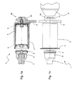
- Fig. 1 a and 1b show an embodiment of a device 1 according to the invention in different views. While Fig. 1 a shows the device 1 in cross section is Fig. 1 b a side view, which additionally shows a head portion of a container to be filled 2 to illustrate the purpose and operation of the device.
- the container 2 to be filled here is a pressure container, in particular an aerosol which can be filled with an aerosol, as used, for example, for painting automobile parts.
- propellant and solvent may already be contained in the container 2, so that a superatmospheric pressure prevails in the container 2.
- the in Fig. 1 b shown section of the container 2 shows in particular the container head, in which a - not shown - valve is arranged, which closes the also formed in the head of the container 2 opening.
- the container 2 In order to fill the container 2 for the first time or further, which may be desirable in particular for the metered addition of colored lacquer or any other substance used in the surface coating, the container 2 is connected with its head to the device 1.
- the inventive design of the device 1, the container 2 can then be filled under pressure with a fluid, after completion of the filling, a cleaning of the device 1 is not necessary, but is replaced by the simple replacement of the inner container 4 and possibly the piston 5 ,
- the device 1 has a pressure device for pushing the fluid into the container 2, which consists essentially of a pressure-resistant outer container 3 and an inner container 4, which fits into the outer container 3 in a form-fitting manner and can be easily inserted into the outer container 3 or can push out of this.
- the fluid to be filled in the container 2 is located at the beginning of the filling process in the inner container 4, but is pressed during filling by means of a piston 5 through an outlet opening in the container 2.
- both the inner container 4 and the piston 5 are plastic parts that are inexpensive to produce, for example, injection-molded polypropylene.
- the inner container 4 clothes the outer container 3 in the sense of an "inlet" on its inner walls completely, whereby a direct contact of the fluid to the outer container 3 is excluded.
- Fig. 1 a the piston 5 is shown in three different phases of the filling process, first outside the inner container 4, then entering the inner container 4 (see dashed line for reference numeral 5) and finally after completion of the filling operation upon reaching the cylinder head (see another dashed line for Reference numeral 5).
- a cylinder-piston arrangement is realized by which can be applied to the filling of the container 2 necessary pressure on the fluid.
- the piston 5 is actuated by means of a punch 7, which is connected via an adapter piece 6 with the piston 5.
- the punch 7 purely mechanical (by manual force, possibly by means of an actuating mechanism), electromechanically, hydraulically and / or pneumatically driven, depending on the practical application of the device appropriate can be.
- the outer container 3 and the inner container 4 comprehensive printing device is attached in the present example to a frame 8 to ensure a fixation.
- the frame 8 can be a movable unit of the most varied type, which can be moved, for example pivoted or lifted, which may be expedient in the context of automated filling.
- the inner container 4 has a substantially cylindrical shape, wherein an outlet opening is formed in the head-side region ("cylinder head").
- an outlet pipe 41 is arranged, which is formed integrally with the inner container 4.
- the outlet pipe 41 has an end 42 facing away from the inner container 4, to which a contact region 43 adjoins, which is at least partially conically shaped.
- Another effect of the illustrated design of the inner container 4 is that the end 42 of the outlet pipe 41 during the connection process on a valve 2 located on the container 2 butt (not shown) abuts, whereby the opening for filling the container 2 is released.
- webs 44 are arranged around the outlet pipe 41.
- a phase is formed at the foot-side inner edge.
- the handles allow easy removal of the inner container 4 from the outer container.
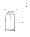
- Fig. 3 shows in cross-sectional view the outer container 3. It is a substantially cylindrical member which is designed to accommodate high pressures and therefore preferably made of metal (aluminum, steel, or the like.) Is made. Since it is a rotationally symmetrical component that ensures secure fit against the container 2 and the inner container 4 should be worked exactly, this may be a turned part.
- the outer container 3 also has an outlet opening, which in Fig. 3 can be seen in the right part of the illustration. The outlet opening of the outer container 3 is dimensioned such that the outlet pipe 41 of the inner container 4 is largely received by this form-fitting manner.
- a coupling portion 32 is formed, which serves to connect the container 2.
- the coupling portion 32 extends on the outer circumference around the outlet opening of the outer container 3 and substantially comprises an annular groove 31 and subsequently a straight section, which is terminated by a shoulder. In the annular groove 31, a spring ring (not shown) is used. In the connected state, the coupling portion 32 protrudes into a coupling portion (not shown) formed complementary to the container 2, wherein a positive and non-positive connection results due to suitable fit and the engagement of the spring ring in an annular groove formed on the container 2.
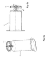
- Fig. 4a and 4b show the piston 5 in side and cross-sectional view. It can clearly be seen that the outer surface of the piston 5, which is peripherally adjacent to the inner container 4, has approximately a U-profile in the circumferential direction. Since the piston 5 is made of the same material (plastic) as the inner container 4, two resilient sealing lips are created by the U-profile, which cling to this due to a certain excess of the piston 5 relative to the inner container 4. A high sealing effect is the result.
- a substantially dome-shaped piston foot 51 is formed, which is provided with two side slots.
- the piston 51 can be used to attach the piston 5 on the adapter piece 6, the punch 7 or the like .
- the piston 51 can be used in an advantageous manner to protect the end of the outlet pipe 41 during transport or storage of the inner container 4.
- the piston foot 51 is preferably dimensioned such that it contacts the outlet pipe 41 only in the region of the radially projecting webs 44. The end 42 and the contact area 43 are therefore particularly protected.
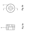
- the adapter 6 is shown in cross-sectional or side view.
- this may be a metallic component, in particular a turned part made of aluminum, steel or the like.
- the punch 7 hole with internal thread left side in Fig. 5a
- a serving for receiving the piston foot 51 passage right side in Fig. 5a ).
Landscapes
- Engineering & Computer Science (AREA)
- Mechanical Engineering (AREA)
- Chemical & Material Sciences (AREA)
- Dispersion Chemistry (AREA)
- Containers And Packaging Bodies Having A Special Means To Remove Contents (AREA)
Applications Claiming Priority (1)
| Application Number | Priority Date | Filing Date | Title |
|---|---|---|---|
| DE200710057209 DE102007057209A1 (de) | 2007-11-26 | 2007-11-26 | Vorrichtung zum Befüllen eines Behälters mit einem Fluid |
Publications (1)
| Publication Number | Publication Date |
|---|---|
| EP2062821A1 true EP2062821A1 (fr) | 2009-05-27 |
Family
ID=40385076
Family Applications (1)
| Application Number | Title | Priority Date | Filing Date |
|---|---|---|---|
| EP08020516A Withdrawn EP2062821A1 (fr) | 2007-11-26 | 2008-11-26 | Dispositif de remplissage d'un récipient avec un liquide |
Country Status (2)
| Country | Link |
|---|---|
| EP (1) | EP2062821A1 (fr) |
| DE (1) | DE102007057209A1 (fr) |
Cited By (1)
| Publication number | Priority date | Publication date | Assignee | Title |
|---|---|---|---|---|
| US8839827B2 (en) | 2010-12-07 | 2014-09-23 | Seymour Of Sycamore, Inc. | Aerosol container filling system |
Families Citing this family (2)
| Publication number | Priority date | Publication date | Assignee | Title |
|---|---|---|---|---|
| PL3647210T3 (pl) | 2018-10-31 | 2021-12-13 | Wisespray International Oy | Urządzenie napełniające do napełniania pojemnika aerozolowego cieczą |
| DE102020115864A1 (de) | 2020-06-16 | 2021-12-16 | Mipa Se | Abfülleinrichtung, Fluidbehälter, Wechselkappe sowie Verfahren zum Betreiben einer Abfülleinrichtung |
Citations (3)
| Publication number | Priority date | Publication date | Assignee | Title |
|---|---|---|---|---|
| US3444906A (en) * | 1964-10-30 | 1969-05-20 | Sprayon Products | Apparatus for filling aerosol cans |
| US5433848A (en) * | 1991-04-09 | 1995-07-18 | Kpa, Inc. | Water filtration pump with disposable filter cartridges |
| US5740841A (en) * | 1994-06-24 | 1998-04-21 | Hirz; Donald J. | Can filling apparatus |
Family Cites Families (4)
| Publication number | Priority date | Publication date | Assignee | Title |
|---|---|---|---|---|
| US3335765A (en) * | 1964-01-27 | 1967-08-15 | Sprayon Products | Packaging of aerosol products |
| EP0440477B2 (fr) * | 1990-01-31 | 2001-02-14 | George Ray | Dispositif de remplissage pour récipient aérosol |
| DE9319019U1 (de) * | 1993-12-11 | 1994-01-27 | Upat Max Langensiepen Kg | Austragkartusche |
| US6138720A (en) * | 1999-05-26 | 2000-10-31 | Zeigler; Edward William | Reduced volatile emissions pneumatic aerosol can filling machine |
-
2007
- 2007-11-26 DE DE200710057209 patent/DE102007057209A1/de not_active Withdrawn
-
2008
- 2008-11-26 EP EP08020516A patent/EP2062821A1/fr not_active Withdrawn
Patent Citations (3)
| Publication number | Priority date | Publication date | Assignee | Title |
|---|---|---|---|---|
| US3444906A (en) * | 1964-10-30 | 1969-05-20 | Sprayon Products | Apparatus for filling aerosol cans |
| US5433848A (en) * | 1991-04-09 | 1995-07-18 | Kpa, Inc. | Water filtration pump with disposable filter cartridges |
| US5740841A (en) * | 1994-06-24 | 1998-04-21 | Hirz; Donald J. | Can filling apparatus |
Cited By (2)
| Publication number | Priority date | Publication date | Assignee | Title |
|---|---|---|---|---|
| US8839827B2 (en) | 2010-12-07 | 2014-09-23 | Seymour Of Sycamore, Inc. | Aerosol container filling system |
| US8985163B2 (en) | 2010-12-07 | 2015-03-24 | Seymour Of Sycamore Inc. | Aerosol container filling system |
Also Published As
| Publication number | Publication date |
|---|---|
| DE102007057209A1 (de) | 2009-05-28 |
Similar Documents
| Publication | Publication Date | Title |
|---|---|---|
| DE69822216T2 (de) | Mehrteilige spritze zum manuellen auftragen von substanzen | |
| EP0254969B1 (fr) | Dispositif pour l'extrusion de matières pâteuses | |
| EP2134475B1 (fr) | Dispositif pour pulvériser des liquides pigmentés | |
| EP2605857B1 (fr) | Module de distribution | |
| EP1652589A2 (fr) | Dispositif de mélange et de distribution comprenant deux récipients | |
| EP1327478B1 (fr) | Poussoir d'une pompe aspirante et foulante pour la pulvérisation d'une produit contenu dans un récipient | |
| EP0213073A1 (fr) | Dispositif pour mélanger et appliquer des substances fluides ou pâteuses | |
| DE4342680A1 (de) | Austragvorrichtung für Medien | |
| DE1926386A1 (de) | Abzapfeinrichtung | |
| EP0521022A1 (fr) | Applicateur pour milieux. | |
| EP3048081A1 (fr) | Systeme de bloc de soupapes pour un appareil de fixation de bouteille | |
| EP1746045B1 (fr) | Dispositif distributeur multichambres | |
| DE4005342C2 (fr) | ||
| DE3420324A1 (de) | Abgabevorrichtung fuer mehrere stroemungsfaehige materialkomponenten | |
| EP2062821A1 (fr) | Dispositif de remplissage d'un récipient avec un liquide | |
| EP2654967B1 (fr) | Distributeur pour un liquide | |
| DE3823708C2 (de) | Motorisch angetriebene Einrichtung zum Dosieren und Mischen von wenigstens zwei Substanzen | |
| DE1929844A1 (de) | Geraet zum Abgeben von Verbrauchsstoffen,z.B. Rasierkrem | |
| DE19632717C2 (de) | Pneumatische Kartuschenauspreßvorrichtung | |
| EP2158136B1 (fr) | Dispositif de déversement d'une substance apte à l'écoulement | |
| DE2156605A1 (de) | Spritzpistole für zwei Komponenten-Spritz mittel | |
| DE3626841A1 (de) | Abgabevorrichtung fuer ein fluessiges produkt, insbesondere ein kosmetisches produkt, beispielsweise nagellack | |
| DE2916699A1 (de) | Austeil- und mischventil fuer zwei getrennt in einem behaelter aufbewahrte, druckgasbeaufschlagte fluessigkeiten | |
| DE19723134A1 (de) | Austragvorrichtung für Medien | |
| DE4431181C1 (de) | Behälter für Flüssigkeiten |
Legal Events
| Date | Code | Title | Description |
|---|---|---|---|
| PUAI | Public reference made under article 153(3) epc to a published international application that has entered the european phase |
Free format text: ORIGINAL CODE: 0009012 |
|
| AK | Designated contracting states |
Kind code of ref document: A1 Designated state(s): AT BE BG CH CY CZ DE DK EE ES FI FR GB GR HR HU IE IS IT LI LT LU LV MC MT NL NO PL PT RO SE SI SK TR |
|
| AX | Request for extension of the european patent |
Extension state: AL BA MK RS |
|
| 17P | Request for examination filed |
Effective date: 20090921 |
|
| 17Q | First examination report despatched |
Effective date: 20091016 |
|
| AKX | Designation fees paid |
Designated state(s): AT BE BG CH CY CZ DE DK EE ES FI FR GB GR HR HU IE IS IT LI LT LU LV MC MT NL NO PL PT RO SE SI SK TR |
|
| STAA | Information on the status of an ep patent application or granted ep patent |
Free format text: STATUS: THE APPLICATION IS DEEMED TO BE WITHDRAWN |
|
| 18D | Application deemed to be withdrawn |
Effective date: 20110601 |