EP1651923B1 - Ölkühler mit befestigungsmittel - Google Patents
Ölkühler mit befestigungsmittel Download PDFInfo
- Publication number
- EP1651923B1 EP1651923B1 EP04740960.2A EP04740960A EP1651923B1 EP 1651923 B1 EP1651923 B1 EP 1651923B1 EP 04740960 A EP04740960 A EP 04740960A EP 1651923 B1 EP1651923 B1 EP 1651923B1
- Authority
- EP
- European Patent Office
- Prior art keywords
- oil cooler
- receiving element
- latching
- receptacle
- connection
- Prior art date
- Legal status (The legal status is an assumption and is not a legal conclusion. Google has not performed a legal analysis and makes no representation as to the accuracy of the status listed.)
- Expired - Lifetime
Links
- 239000000463 material Substances 0.000 claims description 13
- 210000002105 tongue Anatomy 0.000 claims description 11
- 238000003892 spreading Methods 0.000 claims description 3
- 238000004519 manufacturing process Methods 0.000 claims description 2
- 238000009434 installation Methods 0.000 claims 1
- 238000009826 distribution Methods 0.000 description 8
- 238000003780 insertion Methods 0.000 description 8
- 230000037431 insertion Effects 0.000 description 8
- 230000001133 acceleration Effects 0.000 description 4
- 230000005540 biological transmission Effects 0.000 description 2
- 238000001816 cooling Methods 0.000 description 2
- 230000000694 effects Effects 0.000 description 2
- 230000002349 favourable effect Effects 0.000 description 2
- 238000004378 air conditioning Methods 0.000 description 1
- 238000005520 cutting process Methods 0.000 description 1
- 230000001066 destructive effect Effects 0.000 description 1
- 239000007769 metal material Substances 0.000 description 1
- 238000003860 storage Methods 0.000 description 1
Images
Classifications
-
- F—MECHANICAL ENGINEERING; LIGHTING; HEATING; WEAPONS; BLASTING
- F28—HEAT EXCHANGE IN GENERAL
- F28F—DETAILS OF HEAT-EXCHANGE AND HEAT-TRANSFER APPARATUS, OF GENERAL APPLICATION
- F28F9/00—Casings; Header boxes; Auxiliary supports for elements; Auxiliary members within casings
- F28F9/001—Casings in the form of plate-like arrangements; Frames enclosing a heat exchange core
- F28F9/002—Casings in the form of plate-like arrangements; Frames enclosing a heat exchange core with fastening means for other structures
-
- F—MECHANICAL ENGINEERING; LIGHTING; HEATING; WEAPONS; BLASTING
- F01—MACHINES OR ENGINES IN GENERAL; ENGINE PLANTS IN GENERAL; STEAM ENGINES
- F01P—COOLING OF MACHINES OR ENGINES IN GENERAL; COOLING OF INTERNAL-COMBUSTION ENGINES
- F01P11/00—Component parts, details, or accessories not provided for in, or of interest apart from, groups F01P1/00 - F01P9/00
- F01P11/08—Arrangements of lubricant coolers
-
- F—MECHANICAL ENGINEERING; LIGHTING; HEATING; WEAPONS; BLASTING
- F28—HEAT EXCHANGE IN GENERAL
- F28D—HEAT-EXCHANGE APPARATUS, NOT PROVIDED FOR IN ANOTHER SUBCLASS, IN WHICH THE HEAT-EXCHANGE MEDIA DO NOT COME INTO DIRECT CONTACT
- F28D1/00—Heat-exchange apparatus having stationary conduit assemblies for one heat-exchange medium only, the media being in contact with different sides of the conduit wall, in which the other heat-exchange medium is a large body of fluid, e.g. domestic or motor car radiators
- F28D1/02—Heat-exchange apparatus having stationary conduit assemblies for one heat-exchange medium only, the media being in contact with different sides of the conduit wall, in which the other heat-exchange medium is a large body of fluid, e.g. domestic or motor car radiators with heat-exchange conduits immersed in the body of fluid
- F28D1/04—Heat-exchange apparatus having stationary conduit assemblies for one heat-exchange medium only, the media being in contact with different sides of the conduit wall, in which the other heat-exchange medium is a large body of fluid, e.g. domestic or motor car radiators with heat-exchange conduits immersed in the body of fluid with tubular conduits
- F28D1/0408—Multi-circuit heat exchangers, e.g. integrating different heat exchange sections in the same unit or heat exchangers for more than two fluids
- F28D1/0426—Multi-circuit heat exchangers, e.g. integrating different heat exchange sections in the same unit or heat exchangers for more than two fluids with units having particular arrangement relative to the large body of fluid, e.g. with interleaved units or with adjacent heat exchange units in common air flow or with units extending at an angle to each other or with units arranged around a central element
- F28D1/0452—Combination of units extending one behind the other with units extending one beside or one above the other
-
- F—MECHANICAL ENGINEERING; LIGHTING; HEATING; WEAPONS; BLASTING
- F01—MACHINES OR ENGINES IN GENERAL; ENGINE PLANTS IN GENERAL; STEAM ENGINES
- F01P—COOLING OF MACHINES OR ENGINES IN GENERAL; COOLING OF INTERNAL-COMBUSTION ENGINES
- F01P2060/00—Cooling circuits using auxiliaries
- F01P2060/04—Lubricant cooler
-
- F—MECHANICAL ENGINEERING; LIGHTING; HEATING; WEAPONS; BLASTING
- F01—MACHINES OR ENGINES IN GENERAL; ENGINE PLANTS IN GENERAL; STEAM ENGINES
- F01P—COOLING OF MACHINES OR ENGINES IN GENERAL; COOLING OF INTERNAL-COMBUSTION ENGINES
- F01P2070/00—Details
- F01P2070/52—Details mounting heat-exchangers
-
- F—MECHANICAL ENGINEERING; LIGHTING; HEATING; WEAPONS; BLASTING
- F28—HEAT EXCHANGE IN GENERAL
- F28D—HEAT-EXCHANGE APPARATUS, NOT PROVIDED FOR IN ANOTHER SUBCLASS, IN WHICH THE HEAT-EXCHANGE MEDIA DO NOT COME INTO DIRECT CONTACT
- F28D21/00—Heat-exchange apparatus not covered by any of the groups F28D1/00 - F28D20/00
- F28D2021/0019—Other heat exchangers for particular applications; Heat exchange systems not otherwise provided for
- F28D2021/008—Other heat exchangers for particular applications; Heat exchange systems not otherwise provided for for vehicles
- F28D2021/0089—Oil coolers
-
- F—MECHANICAL ENGINEERING; LIGHTING; HEATING; WEAPONS; BLASTING
- F28—HEAT EXCHANGE IN GENERAL
- F28F—DETAILS OF HEAT-EXCHANGE AND HEAT-TRANSFER APPARATUS, OF GENERAL APPLICATION
- F28F2275/00—Fastening; Joining
- F28F2275/08—Fastening; Joining by clamping or clipping
- F28F2275/085—Fastening; Joining by clamping or clipping with snap connection
Definitions
- Oil cooler are fastened by means of a fastener at least indirectly on the vehicle frame. In most cases, this is done by placing the oil cooler below, in front of or behind another radiator and supporting it with fasteners. Oil coolers have length expansions, especially in their main extension direction, which can not be neglected due to the not insignificant temperature differences between operating temperature and ambient temperature during mounting. In addition, the oil cooler is due to its mass and the inflowing under pressure transmission oil also considerable acceleration forces and moments that must be absorbed by appropriate fasteners. Therefore, it has since been customary to provide a screw hole in the region of the oil cooler which penetrates the oil cooler and through which a screw bolt can be passed. The screw is a secure mounting of the oil cooler to a fastener, but has the disadvantage that it is difficult to assemble. Such elaborate fasteners, however, are considered necessary for keeping the oil cooler safe while driving. Fasteners and recording are made of metallic materials to allow appropriate stability, which have the disadvantage that they have a high weight.
- the US 6 059 019 A discloses a heat exchanger assembly with support brackets for mounting the respective heat exchangers.
- the object of the invention is therefore to provide an oil cooler with a fastener that is simple and inexpensive to manufacture and assemble.
- an oil cooler with a device for fastening the oil cooler in a vehicle according to claim 1.
- the oil cooler with the device for fixing the oil cooler on an oil cooler receptacle wherein the oil cooler is mounted in the oil cooler receptacle, wherein between oil cooler receptacle and oil cooler is a snap connection, wherein the oil cooler receptacle has a main body and a U-shaped receiving portion, the two parallel spaced apart aligned legs, which are interconnected by means of a spine, wherein the locking connection consists of a oil cooler receiving side locking means and is provided on the legs, wherein the spine integrally formed material tongues, which serve as spring leaves of a spring accumulator, and the locking means in a detent recess of the Oil cooler engages.
- a particularly advantageous form of locking connection are clip connections, wherein preferably a clip connection is used, which is non-destructive solvable.
- a clip connection is in particular a connection in which a holding element for fixing a functional element is fixed on the one hand to a component and on the other hand engages behind the functional element in particular form-fit or positive and non-positive. This is in the context of the application of an attachment of an oil cooler, because this is the preferred application.
- another auxiliary cooler which is to be arranged in the vehicle, can also replace the oil cooler.
- a force accumulator is provided, which is part of the latching connection and keeps the oil cooler biased in a defined desired position.
- the energy accumulator is in particular a spring accumulator, which is formed from a material tongue, which is formed on the latching receptacle and is correspondingly prestressed upon insertion of the oil cooler into the latching receptacle.
- the spring accumulator is additionally dovetailed split in the direction of action of the spring accumulator and thus an alignment of the oil cooler in the oil cooler receptacle in a further direction is made possible.
- a corresponding mold section such as a functional element of the oil cooler
- a housing portion of the oil cooler penetrates into the opening of the dovetail and is centered by the two flanks.
- the plant of the dovetail to the corresponding element of the oil cooler is also achieved by the spring action.
- the two contact points on the flanks and the support on the catch then ideally form a three-point support, which allows a particularly well-defined holding the oil cooler.
- the oil cooler receptacle is formed so elastic that during insertion of the oil cooler in the oil cooler receptacle spreading of the legs of the U-shape takes place, this elastic spreading is at least partially reversed during engagement of the latching connection.
- the legs of a U-shaped oil cooler receptacle are preferably vertically spaced apart in mounting position of the oil cooler receptacle and aligned in the vehicle transverse direction. This corresponds to a training in which the legs of the U-shaped receptacle over the oil cooler over and under and the oil cooler is arranged horizontally aligned transversely to the direction of travel in the vehicle.
- the arrangement of the oil cooler can be provided both below and in front of or behind another cooler.
- the oil cooler receptacle is at least indirectly attached to the vehicle, the fasteners of the oil cooler intake are preferably positionally adjustable, including in particular slots are provided.
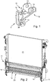
- the Fig. 1 shows in perspective view an oil cooler receptacle 10.
- the oil cooler receptacle consists of a U-shaped receiving portion 11 and a base body 12.
- the main body 12 has fasteners 13 which are each formed as a slot and serve at least indirectly vehicle-mounted attachment of the oil cooler.
- the receptacle 11 is U-shaped and comprises two mutually parallel aligned vertically spaced legs 14 and a back rib 15 which connects the two legs 14 together.
- Each of the two legs 14 has a latching lug 16 which serves to engage in a latching recess 17 of the oil cooler. In this case, an at least partially positive-locking system is generated. It is also possible that the locking lug 16 engages behind a form portion of the locking recess 17, so that in addition to the positive connection and adhesion can be present.
- the spine 15 has integrally formed material tongues 19, which are bent in such a way that they protrude into the insertion space of the oil cooler 18 between the two legs 14 of the oil cooler receptacle 10. Due to the inherent elasticity of the material used, the material tongues 19 serve as spring leaves of a spring accumulator.
- the material tongues 19 are split dovetailed at their free ends, wherein the V-shaped inner sides form flanks 25, which serve the centering receiving the oil cooler.
- the Fig. 2 shows a three-dimensional perspective view of the arrangement of an oil cooler 18 in a region behind an auxiliary cooler 20, which is arranged below the main radiator 21.
- an oil cooler 18 on both sides of the extension of the oil cooler in the vehicle transverse direction per a receptacle 11 attached to the additional cooler 20 and its holder. Between the legs 14 of the oil cooler receptacle 10 of the oil cooler 18 is held.
- the oil cooler extends parallel to the other radiators in the vehicle transverse direction, wherein in the figure is a view showing the viewing direction in the direction of travel from a point behind the arrangement of the radiator in the vehicle.
- the oil cooler 18 In the direction of flow of the air flow flowing through the radiator, the oil cooler 18 is thus arranged behind the auxiliary radiator 20, which may be, for example, the radiator of an air conditioning system.
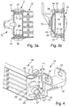
- the Fig. 3a and 3b show sectional views in different cutting directions through an oil cooler and an oil cooler intake. From the cut of Fig. 3a can be seen in a particularly favorable manner, as the engaging of the two legs 14 of the receptacle 11 of the oil cooler receptacle 10, the locking lugs 16 in the locking recesses 17 of the oil cooler.
- the latching recesses are formed in a respect to the extension of the cooling lines 22, which are traversed by the transmission oil, the vertically oriented distribution channel 23.
- the distribution channel 23 has essentially a cylindrical basic shape and the latching recess 17 is formed in that the cover 24 terminating the distribution channel 23 is set back axially in the direction of extension in relation to the terminal edge.
- the centering effect in the insertion direction can still be increased by acting as spring elements material tongues 19.
- the spine 15, which connects the two legs 14 with each other, has in the introduction of the oil cooler 18 projecting, dovetail-shaped material tongues 19 acting as a spring and due to the abutment of the flanks 25 abut the vertical channel 23 of the oil cooler and this in the execution direction from the Assign record 11 out.
- This serves on the one hand to secure the latching connection, because then a positive connection between locking lug 16 and locking recess 17 can be produced in a particularly favorable manner, and on the other hand, the oil cooler recording the oil cooler also opposite in the direction of travel forces, such as acceleration and deceleration forces supported.
- the Fig. 4 shows the insertion of an oil cooler 18 with a distribution channel 23 and cooling lines 22 in an oil cooler receptacle 10.
- the oil cooler receptacle has a base body 12, the fastening means 13, such as slots, so that the oil cooler receptacle is at least indirectly fixed to the vehicle frame.
- the oil cooler receptacle 10 has a receptacle 11 which is U-shaped.
- the two legs 14 protrude horizontally, parallel to each other and aligned in the direction of travel from a spine 15 from.
- the spine 15 has the dovetail-shaped material tongues split as spring storage.
- the legs 14 When inserting the oil cooler, in particular of the projecting into the region of the receptacle 11 distribution channel 23, first, the legs 14 are spread elastically. The edge 26 of the distribution channel 23 comes into abutment with the insertion bevel 27 of the locking lug 16. The legs 14 are spread so far that the locking lugs 16 can slide over the edge 26 and then the locking lugs 16 in the locking recess 17 on Distributor channel 23 fall into it.
- the wall 28 of the distribution channel 23 comes into abutment with the edges 26 of the dovetailed gap of the material tongues 19 and pushes the material tongues 19 from its rest position into a preloaded end position, from which they produce a positive engagement of the detent 16 in the detent recess 17 and the Oil cooler against deflection from this position in the insertion, so the direction of travel of the vehicle or in the opposite direction, field.
- the oil cooler intake is preferably made of plastic, which allows for a low weight and on the other hand adapted plastic deformability with sufficient material rigidity.
Landscapes
- Engineering & Computer Science (AREA)
- Mechanical Engineering (AREA)
- General Engineering & Computer Science (AREA)
- Physics & Mathematics (AREA)
- Thermal Sciences (AREA)
- Chemical & Material Sciences (AREA)
- Combustion & Propulsion (AREA)
- Lubrication Of Internal Combustion Engines (AREA)
Description
- Ölkühler werden mittels einem Befestigungsmittel zumindest mittelbar am Fahrzeugrahmen befestigt. In den meisten Fällen geschieht dies dadurch, dass der Ölkühler unterhalb, vor oder hinter einem anderen Kühler angeordnet wird und hierzu über Befestigungsmittel an diesem abgestützt wird.
Ölkühler weisen Längenausdehnungen vor allem in ihrer Haupterstreckungsrichtung auf, die aufgrund der nicht unerheblichen Temperaturunterschiede zwischen Betriebstemperatur und Umgebungstemperatur bei der Befestigung nicht vernachlässigt werden können. Darüber hinaus unterliegt der Ölkühler aufgrund seiner Masse sowie dem unter Druck anströmenden Getriebeöl auch erheblichen Beschleunigungskräften und Momenten, die durch entsprechende Befestigungsmittel aufgefangen werden müssen.
Daher ist es seither üblich, im Bereich des Ölkühlers ein Schraubloch vorzusehen, das den Ölkühler durchsetzt und durch die hindurch ein Schraubbolzen durchführbar ist. Die Schraubverbindung stellt eine sichere Halterung des Ölkühlers an einem Befestigungsmittel dar, hat jedoch den Nachteil, dass sie mühsam zu montieren ist. Derartig aufwendige Befestigungen werden jedoch für das im Fahrbetrieb sichere Halten des Ölkühlers für erforderlich gehalten. Befestigungselemente und Aufnahme werden dabei aus metallischen Werkstoffen hergestellt, um passende Standfestigkeit zu ermöglichen, wobei diese den Nachteil haben, dass sie ein hohes Gewicht aufweisen. - Die
US 6 059 019 A offenbart eine Wärmetauscheranordnung mit Unterstützungsklammern zur Montage der jeweiligen Wärmetauscher. - Aufgabe der Erfindung ist es daher, einen Ölkühler mit einem Befestigungsmittel bereitzustellen, der einfach und kostengünstig herstell- und montierbar ist.
- Diese Aufgabe wird durch einen Ölkühler mit einer Vorrichtung zur Befestigung des Ölkühlers in einem Fahrzeug, gemäß Anspruch 1 gelöst. Erfindungsgemäss weist der Ölkühler mit der Vorrichtung zur Befestigung des Ölkühlers eine Ölkühleraufnahme auf, bei der der Ölkühler in der Ölkühleraufnahme befestigt ist, wobei zwischen Ölkühleraufnahme und Ölkühler eine Rastverbindung besteht, wobei die Ölkühleraufnahme einen Grundkörper und einen U-förmigen Aufnahmebereich aufweist, der zwei parallel zueinander ausgerichtete beabstandete Schenkel aufweist, die mittels eines Rückenstegs miteinander verbunden sind, wobei die Rastverbindung aus einem ölkühleraufnahmeseitigen Rastmittel besteht und an den Schenkeln vorgesehen ist, wobei der Rückensteg angeformte Materialzungen aufweist, die als Federblätter eines Federspeichers dienen, und das Rastmittel in eine Rastvertiefung des Ölkühlers eingreift.
- Das Verwenden einer Rastverbindung ist deshalb vorteilhaft, weil diese bei der Montage des Ölkühlers in besonders einfacher Weise hergestellt werden kann. Eine besonders günstige Form der Rastverbindung sind Clipverbindungen, wobei vorzugsweise eine Clipverbindung Verwendung findet, welche zerstörungsfrei lösbar ist. Eine Clipverbindung ist dabei insbesondere eine Verbindung, bei der ein Halteelement zur Befestigung eines Funktionselements einerseits an einem Bauteil festgelegt ist und andererseits das Funktionselement insbesondere form- bzw. form-und kraftschlüssig hintergreift. Hierbei ist im Rahmen der Anmeldung von einer Befestigung eines Ölkühlers die Rede, weil dies die bevorzugte Anwendung ist. Prinzipiell kann an die Stelle des Ölkühlers auch ein anderer Zusatzkühler treten, welcher im Fahrzeug anzuordnen ist.
Gemäß bevorzugter Ausgestaltung der Erfindung ist ein Kraftspeicher vorgesehen, der Teil der Rastverbindung ist und den Ölkühler in einer definierten Solllage vorgespannt hält. Bei dem Kraftspeicher handelt es sich insbesondere um einen Federspeicher, welcher aus einer Materialzunge gebildet wird, die an der Rastaufnahme ausgebildet ist und beim Einführen des Ölkühlers in die Rastaufnahme entsprechend vorgespannt wird. Durch die Verwendung des Federspeichers wird der Ölkühler in einer insbesondere in Einführrichtung des Ölkühlers in die Ölkühleraufnahme definierten Stellung gehalten. Das Spiel, das erforderlich ist, um die Rastverbindung bzw. Clipverbindung herzustellen, wird durch das Vorspannen des Federspeichers aufgehoben. Der Federspeicher wirkt insbesondere den auf den Ölkühler einwirkenden Beschleunigungskräften und Anströmkräften entgegen. Darüber hinaus ist es vorteilhaft, wenn der Federspeicher zusätzlich in Wirkrichtung des Federspeichers schwalbenschwanzförmig gespalten ist und hierdurch ein Ausrichten des Ölkühlers in der Ölkühleraufnahme in einer weiteren Richtung ermöglicht wird. Dies geschieht vorzugsweise dadurch, dass ein entsprechender Formabschnitt, wie ein Funktionselement des Ölkühlers, beispielsweise ein Gehäuseabschnitt des Ölkühlers in die Öffnung des Schwalbenschwanzes eindringt und von den beiden Flanken zentriert wird. Die Anlage des Schwalbenschwanzes an das entsprechende Element des Ölkühlers wird dabei ebenfalls durch die Federwirkung erreicht. Die beiden Anlagepunkte an den Flanken sowie die Abstützung an der Raste bilden dann idealerweise eine Dreipunktabstützung, welche ein besonders gut definiertes Halten des Ölkühlers ermöglicht. Es kann vorgesehen sein, dass die Ölkühleraufnahme so elastisch ausgebildet ist, dass beim Einführen des Ölkühlers in die Ölkühleraufnahme ein Aufspreizen der Schenkel der U-Form erfolgt, wobei dieses elastische Aufspreizen während des Einrastens der Rastverbindung wenigstens teilweise reversiert wird.
Die Schenkel einer U-förmig ausgebildeten Ölkühleraufnahme sind dabei vorzugsweise in Montagelage der Ölkühleraufnahme vertikal zueinander beabstandet und in Fahrzeugquerrichtung ausgerichtet. Dies entspricht einer Ausbildung, in der die Schenkel der U-förmigen Aufnahme den Ölkühler über- bzw. untergreifen und der Ölkühler quer zur Fahrtrichtung im Fahrzeug horizontal ausgerichtet angeordnet ist. Die Anordnung des Ölkühlers kann dabei sowohl unterhalb als auch vor oder hinter einem anderen Kühler vorgesehen sein.
Gemäß weiterer Ausgestaltung der Erfindung ist die Ölkühleraufnahme zumindest mittelbar am Fahrzeug befestigt, wobei die Befestigungen der Ölkühleraufnahme vorzugsweise lagejustierbar sind, wozu insbesondere Langlöcher vorgesehen sind. - Im Übrigen ist die Erfindung anhand des in der Zeichnung dargestellten Ausführungsbeispiels näher erläutert; dabei zeigt:
- Fig. 1
- die perspektivische Ansicht einer Ölkühleraufnahme;
- Fig. 2
- einen mittels einer Ölkühleraufnahme an einem weiteren Kühler gehaltenen Ölkühler;
- Fig. 3a,3b
- in unterschiedlichen Schnittdarstellungen die Halterung des Ölkühlers in der Ölkühleraufnahme; und
- Fig. 4
- in dreidimensionaler Darstellung das Einführen eines Ölkühlers in die Ölkühleraufnahme.
- Die
Fig. 1 zeigt in perspektivischer Darstellung eine Ölkühleraufnahme 10. Die Ölkühleraufnahme besteht aus einem U-förmigen Aufnahmebereich 11 und einem Grundkörper 12. Der Grundkörper 12 weist Befestigungen 13 auf, die jeweils als Langloch ausgebildet sind und der wenigstens mittelbar fahrzeugseitigen Befestigung des Ölkühlers dienen. - Die Aufnahme 11 ist U-förmig ausgebildet und umfasst zwei zueinander parallel ausgerichtete vertikal zueinander beabstandete Schenkel 14 und einen Rückensteg 15, der die beiden Schenkel 14 miteinander verbindet. Jeder der beiden Schenkel 14 weist eine Rastnase 16 auf, die dem Einrasten in eine Rastvertiefung 17 des Ölkühlers dient. Hierbei wird eine zumindest abschnittsweise formschlüssige Anlage erzeugt. Es ist auch möglich, das die Rastnase 16 einen Formabschnitt der Rastvertiefung 17 hintergreift, so dass neben dem Formschluss auch Kraftschluss vorliegen kann. Durch das Verrasten der Rastnasen 16 in der Rastvertiefung 17 der beiden Schenkel 14 wird eine sichere Befestigung eines Ölkühlers 18 in der Ölkühleraufnahme 10 erreicht.
- Der Rückensteg 15 weist angeformte Materialzungen 19 auf, die derart abgekröpft sind, dass sie in den Einführraum des Ölkühlers 18 zwischen den beiden Schenkeln 14 der Ölkühleraufnahme 10 hineinragen. Aufgrund der Eigenelastizität des verwendeten Materials dienen die Materialzungen 19 als Federblätter eines Federspeichers. Die Materialzungen 19 sind dabei an ihren freien Enden schwalbenschwanzförmig gespalten, wobei die V-förmigen Innenseiten Flanken 25 bilden, die der zentrierenden Aufnahme des Ölkühlers dienen.
- Die
Fig. 2 zeigt in dreidimensionaler perspektivischer Darstellung die Anordnung eines Ölkühlers 18 in einem Bereich hinter einem Zusatzkühler 20, welcher unterhalb des Hauptkühlers 21 angeordnet ist. Hierzu ist beidseits der Erstreckung des Ölkühlers in Fahrzeugquerrichtung je eine Aufnahme 11 am Zusatzkühler 20 bzw. dessen Halterung befestigt. Zwischen den Schenkeln 14 der Ölkühleraufnahme 10 ist der Ölkühler 18 gehalten. Dabei erstreckt sich der Ölkühler parallel zu den weiteren Kühlern in Fahrzeugquerrichtung, wobei in der Figur eine Ansicht dargestellt ist, die die Blickrichtung in Fahrtrichtung von einem Punkt hinter der Anordnung der Kühler im Fahrzeug zeigt. In Anströmrichtung des die Kühler durchströmenden Luftstromes liegt der Ölkühler 18 somit hinter dem Zusatzkühler 20, bei dem es sich beispielsweise um den Kühler eines Klimatisierungssystemes handeln kann, angeordnet. - Die
Fig. 3a und 3b zeigen Schnittdarstellungen in unterschiedlichen Schnittrichtungen durch einen Ölkühler und eine Ölkühleraufnahme. Aus dem Schnitt derFig. 3a ist in besonders günstiger Weise zu erkennen, wie die von den beiden Schenkeln 14 der Aufnahme 11 der Ölkühleraufnahme 10 die Rastnasen 16 in die Rastvertiefungen 17 des Ölkühlers eingreifen. Dabei sind die Rastvertiefungen in einem bezüglich der Erstreckung der Kühlleitungen 22, welche von dem Getriebeöl durchströmt werden, des senkrecht ausgerichteten Verteilerkanal 23 ausgebildet. Der Verteilerkanal 23 weist im Wesentlichen eine zylindrische Grundform auf und die Rastvertiefung 17 ist dadurch ausgebildet, dass der den Verteilerkanal 23 abschließende Deckel 24 gegenüber der Abschlusskante in Erstreckungsrichtung axial zurückversetzt ist. Durch entsprechende Anpassung des Durchmessers und der Form der Rastnase 16 der Schenkel 14 kann darüber hinaus eine entsprechende Zentrierwirkung für den Ölkühler in der Befestigung erreicht werden. Durch den gleichzeitigen Eingriff an den beiden einander gegenüberliegenden Enden des Verteilerkanals wird eine Zentrierung und Fixierung der Lage des Ölkühlers 18 in der Aufnahme 11 und somit in der Ölkühleraufnahme 10 erreicht. - Wie insbesondere aus der
Fig. 3b erkenntlich ist, kann die Zentrierwirkung in Einführrichtung noch durch die als Federelemente wirkenden Materialzungen 19 erhöht werden. Der Rückensteg 15, der die beiden Schenkel 14 miteinander verbindet, weist in den Einführraum des Ölkühlers 18 hineinragende, schwalbenschwanzförmig gespaltene Materialzungen 19 auf, die als Federspeicher wirken und aufgrund der Anlage der Flanken 25 am Vertikalkanal 23 des Ölkühlers anliegen und diesen in Ausführrichtung aus der Aufnahme 11 heraus beaufschlagen. Dies dient zum einen der Sicherung der Rastverbindung, weil dann ein Formschluss zwischen Rastnase 16 und Rastvertiefung 17 in besonders günstiger Weise herstellbar ist, und zum anderen die Ölkühleraufnahme den Ölkühler auch gegenüber in Fahrtrichtung verlaufende Kräfte, wie Beschleunigungs- und Verzögerungskräfte, abstützt. - Die
Fig. 4 zeigt den Einführvorgang eines Ölkühlers 18 mit einem Verteilerkanal 23 und Kühlleitungen 22 in eine Ölkühleraufnahme 10. Die Ölkühleraufnahme weist einen Grundkörper 12 auf, der Befestigungsmittel 13, wie Langlöcher, aufweist, damit die Ölkühleraufnahme wenigstens mittelbar am Fahrzeugrahmen festlegbar ist. Zum Halten des Ölkühlers weist die Ölkühleraufnahme 10 eine Aufnahme 11 auf, die U-förmig ausgebildet ist. Die beiden Schenkel 14 ragen horizontal, parallel zueinander und in Fahrtrichtung ausgerichtet von einem Rückensteg 15 ab. Der Rückensteg 15 weist die schwalbenschwanzförmig gespaltenen Materialzungen als Federspeicher auf. Beim Einführen des Ölkühlers, insbesondere des in den Bereich der Aufnahme 11 hineinragenden Verteilerkanals 23, werden zunächst die Schenkel 14 elastisch aufgespreizt. Der Rand 26 des Verteilerkanals 23 gelangt in Anlage mit der Einführschräge 27 der Rastnase 16. Die Schenkel 14 werden so weit aufgespreizt, dass die Rastnasen 16 über den Rand 26 hinweggleiten können und dann die Rastnasen 16 in die Rastvertiefung 17 am Verteilerkanal 23 hineinfallen. Gleichzeitig gelangt die Wandung 28 des Verteilerkanals 23 in Anlage mit den Rändern 26 des schwalbenschwanzförmigen Spalts der Materialzungen 19 und drückt die Materialzungen 19 aus ihrer Ruhelage in eine vorgespannte Endlage, aus der heraus sie eine formschlüssige Anlage der Rastnase 16 in der Rastvertiefung 17 erzeugen und den Ölkühler gegen Auslenken aus dieser Lage in Einführrichtung, also Fahrtrichtung des Fahrzeuges bzw. in Gegenrichtung, auffangen. Dies sind insbesondere einwirkende Beschleunigungs- und Verzögerungskräfte aus dem Fahrbetriebe heraus. Die Ölkühleraufnahme ist dabei vorzugsweise aus Kunststoff hergestellt, was zum einen ein geringes Gewicht und zum anderen eine angepasste plastische Verformbarkeit bei hinreichender Materialsteifigkeit ermöglicht.
Claims (8)
- Ölkühler mit einer Vorrichtung zur Befestigung des Ölkühlers (18) in einem Fahrzeug, mit einer Ölkühleraufnahme, bei der der Ölkühler (18) in der Ölkühleraufnahme (10) befestigt ist, wobei zwischen Ölkühleraufnahme (10) und Ölkühler (18) eine Rastverbindung besteht, wobei die Ölkühleraufnahme einen Grundkörper und einen U-förmigen Aufnahmebereich aufweist, der zwei parallel zueinander ausgerichtete beabstandete Schenkel aufweist, die mittels eines Rückenstegs (15) miteinander verbunden sind, wobei die Rastverbindung aus einem ölkühleraufnahmeseitigen Rastmittel (16) besteht und an den Schenkeln (14) vorgesehen ist, dadurch gekennzeichnet, dass der Rückensteg (15) angeformte Materialzungen (19) aufweist, die als Federblätter eines Federspeichers dienen, und das Rastmittel (16) in eine Rastvertiefung (17) des Ölkühlers (18) eingreift.
- Ölkühler nach Anspruch 1, dadurch gekennzeichnet, dass die Rastmittel (16) und die Rastvertiefung (17) eine Clipverbindung bilden, wobei die Clipverbindung insbesondere zerstörungsfrei lösbar ist.
- Ölkühler nach einem der vorangegangenen Ansprüche, dadurch gekennzeichnet, dass die Rastverbindung durch den Federspeicher in einer Solllage vorgespannt gehalten ist.
- Ölkühler nach einem der vorhergehenden Ansprüche, dadurch gekennzeichnet, dass der Federspeicher zum zusätzlichen Ausrichten in einer weiteren Richtung schwalbenschwanzförmig gespalten ist.
- Ölkühler nach einem der vorhergehenden Ansprüche, dadurch gekennzeichnet, dass die Schenkel der U-Form bei einem Einführen des Ölkühlers (18) in die Ölkühleraufnahme (10) aufspreizbar sind, wobei das Aufspreizen beim Herstellen der Rastverbindung zumindest verringerbar ist.
- Ölkühler nach einem der vorhergehenden Ansprüche, dadurch gekennzeichnet, dass in Montagelage der Ölkühleraufnahme (10) die Schenkel (14) vertikal und zueinander beabstandet und vorzugsweise in Fahrzeuglängsrichtung ausgerichtet sind.
- Ölkühler nach einem der vorhergehenden Ansprüche, dadurch gekennzeichnet, dass die Ölkühleraufnahme (10) fahrzeugseitig befestigbar ist, wobei die Befestigungen (13) vorzugsweise lagejustierbar sind.
- Ölkühler nach einem der vorhergehenden Ansprüche, dadurch gekennzeichnet, dass die Ölkühleraufnahme aus Kunststoff ist.
Applications Claiming Priority (2)
| Application Number | Priority Date | Filing Date | Title |
|---|---|---|---|
| DE10333000A DE10333000A1 (de) | 2003-07-18 | 2003-07-18 | Befestigungsmittel für einen Ölkühler |
| PCT/EP2004/007726 WO2005012821A1 (de) | 2003-07-18 | 2004-07-13 | Befestigungsmittel für einen ölkühler |
Publications (2)
| Publication Number | Publication Date |
|---|---|
| EP1651923A1 EP1651923A1 (de) | 2006-05-03 |
| EP1651923B1 true EP1651923B1 (de) | 2017-09-20 |
Family
ID=34111620
Family Applications (1)
| Application Number | Title | Priority Date | Filing Date |
|---|---|---|---|
| EP04740960.2A Expired - Lifetime EP1651923B1 (de) | 2003-07-18 | 2004-07-13 | Ölkühler mit befestigungsmittel |
Country Status (4)
| Country | Link |
|---|---|
| US (1) | US7575211B2 (de) |
| EP (1) | EP1651923B1 (de) |
| DE (1) | DE10333000A1 (de) |
| WO (1) | WO2005012821A1 (de) |
Families Citing this family (12)
| Publication number | Priority date | Publication date | Assignee | Title |
|---|---|---|---|---|
| US8029021B2 (en) | 2007-03-16 | 2011-10-04 | Polaris Industries Inc. | Vehicle |
| EP2137478A2 (de) * | 2007-04-11 | 2009-12-30 | Behr GmbH & Co. KG | Wärmetauscher |
| US10066878B2 (en) * | 2012-09-29 | 2018-09-04 | Zhejiang Sanhua Automotive Components Co., Ltd. | Heat exchanger integrated assembly and manufacturing method thereof |
| CN118849684A (zh) | 2015-05-15 | 2024-10-29 | 北极星工业有限公司 | 多用途车辆 |
| US11173808B2 (en) | 2016-12-22 | 2021-11-16 | Polaris Industies Inc. | Vehicle |
| GB2558633A (en) * | 2017-01-12 | 2018-07-18 | Denso Marston Ltd | A heat exchanger assembly |
| US10274267B1 (en) * | 2018-03-23 | 2019-04-30 | Denso International America, Inc. | Heat-shrink bracket |
| US10605281B2 (en) * | 2018-08-10 | 2020-03-31 | DENSO International Business Machines Corporation | Component retention assembly |
| CA3299418A1 (en) | 2019-04-30 | 2026-03-02 | Polaris Industries Inc. | Vehicle with removable final drive |
| US12187127B2 (en) | 2020-05-15 | 2025-01-07 | Polaris Industries Inc. | Off-road vehicle |
| US11691674B2 (en) | 2020-05-15 | 2023-07-04 | Polaris Industries Inc. | Off-road vehicle |
| MX2023006716A (es) | 2022-06-13 | 2023-12-14 | Polaris Inc | Tren de potencia para vehiculo utilitario. |
Citations (3)
| Publication number | Priority date | Publication date | Assignee | Title |
|---|---|---|---|---|
| GB1551106A (en) * | 1977-04-05 | 1979-08-22 | Johnson L | Heat exchangers |
| DE19605909A1 (de) * | 1996-02-17 | 1997-08-21 | Behr Gmbh & Co | Wärmeübertrager |
| DE19747887A1 (de) * | 1997-10-30 | 1999-05-27 | Friatec Ag | Halteelement |
Family Cites Families (18)
| Publication number | Priority date | Publication date | Assignee | Title |
|---|---|---|---|---|
| US2863202A (en) * | 1957-10-21 | 1958-12-09 | Atto N Hanna | Paper clamp or the like |
| US4362284A (en) * | 1980-11-03 | 1982-12-07 | Appleton Electric Company | Fastener for attaching electrical boxes to steel studs |
| JP2546505Y2 (ja) * | 1991-05-23 | 1997-09-03 | 株式会社ゼクセル | 熱交換器のブラケット取付構造 |
| DE9114734U1 (de) * | 1991-11-27 | 1992-01-23 | Behr GmbH & Co, 7000 Stuttgart | Halterung für den Kühler eines Kraftfahrzeugmotors |
| US5407161A (en) * | 1993-03-25 | 1995-04-18 | Valeo Engine Cooling, Inc. | Bracket to be secured to a cylindrical object |
| US5429182A (en) * | 1993-09-08 | 1995-07-04 | Showa Aluminum Corporation | Heat exchanger having inlet and outlet pipes for a heat exchanging medium and a method of making same |
| DE4426377A1 (de) * | 1994-07-26 | 1995-09-28 | Daimler Benz Ag | Befestigungsvorrichtung für einen Kühler |
| DE29609262U1 (de) * | 1996-05-23 | 1996-08-14 | Bayerische Motoren Werke AG, 80809 München | Halterung für einen Wärmetauscher |
| DE19731999A1 (de) * | 1997-07-25 | 1999-02-04 | Laengerer & Reich Gmbh & Co | Kühlmodul |
| FR2772902B1 (fr) * | 1997-12-24 | 2000-03-03 | Valeo Thermique Moteur Sa | Dispositif d'assemblage d'accessoires sur un radiateur de refroidissement de vehicule |
| US20010004010A1 (en) | 1998-02-09 | 2001-06-21 | Immanuel Halm | Heat exchanger having snap-on bracket |
| US6254161B1 (en) * | 1999-10-25 | 2001-07-03 | Illinois Tool Works Inc | Reinforcement system for an automotive vehicle fender and bracket therefor |
| FR2811954B1 (fr) * | 2000-07-18 | 2003-01-31 | Ecia Equip Composants Ind Auto | Face avant, bloc avant et vehicule automobile correspondants |
| GB2373571B (en) * | 2001-03-23 | 2004-11-03 | Visteon Global Tech Inc | Heat exchanger |
| LU90826B1 (en) * | 2001-09-07 | 2003-03-10 | Delphi Tech Inc | Assembly of a component of a vehicle air conditioning system to a support structure |
| DE10252879A1 (de) * | 2002-11-12 | 2004-05-27 | Behr Gmbh & Co. Kg | Befestigungsvorrichtung, insbesondere zur Befestigung eines Kühlmoduls an einem Fahrzeugrahmen |
| US6901992B2 (en) * | 2003-06-25 | 2005-06-07 | Delphi Technologies, Inc. | Fastenerless mounting bracket for heat exchangers |
| US7117927B2 (en) * | 2004-09-14 | 2006-10-10 | Delphi Technologies, Inc. | Snap-on mounting bracket for heat exchangers |
-
2003
- 2003-07-18 DE DE10333000A patent/DE10333000A1/de not_active Withdrawn
-
2004
- 2004-07-13 WO PCT/EP2004/007726 patent/WO2005012821A1/de not_active Ceased
- 2004-07-13 US US10/564,787 patent/US7575211B2/en not_active Expired - Fee Related
- 2004-07-13 EP EP04740960.2A patent/EP1651923B1/de not_active Expired - Lifetime
Patent Citations (3)
| Publication number | Priority date | Publication date | Assignee | Title |
|---|---|---|---|---|
| GB1551106A (en) * | 1977-04-05 | 1979-08-22 | Johnson L | Heat exchangers |
| DE19605909A1 (de) * | 1996-02-17 | 1997-08-21 | Behr Gmbh & Co | Wärmeübertrager |
| DE19747887A1 (de) * | 1997-10-30 | 1999-05-27 | Friatec Ag | Halteelement |
Also Published As
| Publication number | Publication date |
|---|---|
| DE10333000A1 (de) | 2005-03-17 |
| WO2005012821A1 (de) | 2005-02-10 |
| EP1651923A1 (de) | 2006-05-03 |
| US20070074848A1 (en) | 2007-04-05 |
| US7575211B2 (en) | 2009-08-18 |
Similar Documents
| Publication | Publication Date | Title |
|---|---|---|
| DE19706199B4 (de) | Elektrische Heizeinrichtung, insbesondere für ein Kraftfahrzeug | |
| DE4142023C2 (de) | Wärmetauschereinheit für Kraftfahrzeuge | |
| DE69300045T2 (de) | Befestigung eines Wärmetauschers mit rohrförmiger Endkammer. | |
| EP1489375A1 (de) | Wärmetauscherblock | |
| DE102007012189B3 (de) | Vorrichtung zur Durchführung von Kabeln | |
| DE10333000A1 (de) | Befestigungsmittel für einen Ölkühler | |
| DE202016104408U1 (de) | Befestigungsclip | |
| EP1439364B1 (de) | Wärmeübertrager mit einem Halter | |
| EP2655918A1 (de) | Schwingungsdämpfende aufnahmevorrichtung | |
| DE102018101983B4 (de) | Aufnahmeanordnung einer Leuchtweitenstelleinrichtung mit Mitteln zur Thermokompensation | |
| EP2418451B1 (de) | Anordnung umfassend einen Wärmeübertrager, eine weitere Komponente und eine Modulhalterung | |
| EP2484554A2 (de) | Vorrichtung zur Befestigung eines Scheinwerfers | |
| EP1757888A2 (de) | Anordnung zur Befestigung eines Wärmeübertragers an einem anderen | |
| DE202005013339U1 (de) | Rastaufnahmeelement und Rastverbindungssystem | |
| EP1371864A1 (de) | Aus federndem Blech bestehendes Klemmstück | |
| DE102007010934B4 (de) | Vorrichtung zur lagegenauen Verbindung eines Magnethalters mit dem Sensorarm einer Schaltgabel eines Kraftfahrzeugschaltgetriebes | |
| DE102016215033A1 (de) | Bewegungstolerante Befestigungseinrichtung | |
| DE102005049140B4 (de) | Vorrichtung zur Befestigung eines Sensors | |
| EP3995332A1 (de) | Aufdachklimaanlage für fahrzeuge | |
| EP0063294B1 (de) | Befestigungsvorrichtung, insbesondere für Armlehnen oder Haltegriffe an der Karosseriewand von Fahrzeugen | |
| DE102009008193A1 (de) | Schutzeinrichtung | |
| EP2110632B1 (de) | Waermetauscher, insbesondere Ladeluftkühler, mit einer rastbaren Befestigungseinrichtung | |
| EP4013656A1 (de) | Befestigung für eine thermische isolierschicht in einem schienenfahrzeug in integralbauweise. | |
| DE202009001790U1 (de) | Präsentationsvorrichtung | |
| DE102009051531A1 (de) | Befestigungssystem |
Legal Events
| Date | Code | Title | Description |
|---|---|---|---|
| PUAI | Public reference made under article 153(3) epc to a published international application that has entered the european phase |
Free format text: ORIGINAL CODE: 0009012 |
|
| 17P | Request for examination filed |
Effective date: 20060220 |
|
| AK | Designated contracting states |
Kind code of ref document: A1 Designated state(s): AT BE BG CH CY CZ DE DK EE ES FI FR GB GR HU IE IT LI LU MC NL PL PT RO SE SI SK TR |
|
| DAX | Request for extension of the european patent (deleted) | ||
| 17Q | First examination report despatched |
Effective date: 20070416 |
|
| RAP1 | Party data changed (applicant data changed or rights of an application transferred) |
Owner name: MAHLE BEHR GMBH & CO. KG |
|
| GRAP | Despatch of communication of intention to grant a patent |
Free format text: ORIGINAL CODE: EPIDOSNIGR1 |
|
| INTG | Intention to grant announced |
Effective date: 20170606 |
|
| GRAS | Grant fee paid |
Free format text: ORIGINAL CODE: EPIDOSNIGR3 |
|
| GRAA | (expected) grant |
Free format text: ORIGINAL CODE: 0009210 |
|
| RIN1 | Information on inventor provided before grant (corrected) |
Inventor name: ANDRITTER, DIRK |
|
| AK | Designated contracting states |
Kind code of ref document: B1 Designated state(s): AT BE BG CH CY CZ DE DK EE ES FI FR GB GR HU IE IT LI LU MC NL PL PT RO SE SI SK TR |
|
| REG | Reference to a national code |
Ref country code: GB Ref legal event code: FG4D Free format text: NOT ENGLISH |
|
| REG | Reference to a national code |
Ref country code: CH Ref legal event code: EP |
|
| REG | Reference to a national code |
Ref country code: AT Ref legal event code: REF Ref document number: 930505 Country of ref document: AT Kind code of ref document: T Effective date: 20171015 |
|
| REG | Reference to a national code |
Ref country code: IE Ref legal event code: FG4D Free format text: LANGUAGE OF EP DOCUMENT: GERMAN |
|
| REG | Reference to a national code |
Ref country code: DE Ref legal event code: R096 Ref document number: 502004015596 Country of ref document: DE |
|
| REG | Reference to a national code |
Ref country code: NL Ref legal event code: MP Effective date: 20170920 |
|
| PG25 | Lapsed in a contracting state [announced via postgrant information from national office to epo] |
Ref country code: FI Free format text: LAPSE BECAUSE OF FAILURE TO SUBMIT A TRANSLATION OF THE DESCRIPTION OR TO PAY THE FEE WITHIN THE PRESCRIBED TIME-LIMIT Effective date: 20170920 Ref country code: SE Free format text: LAPSE BECAUSE OF FAILURE TO SUBMIT A TRANSLATION OF THE DESCRIPTION OR TO PAY THE FEE WITHIN THE PRESCRIBED TIME-LIMIT Effective date: 20170920 |
|
| PG25 | Lapsed in a contracting state [announced via postgrant information from national office to epo] |
Ref country code: GR Free format text: LAPSE BECAUSE OF FAILURE TO SUBMIT A TRANSLATION OF THE DESCRIPTION OR TO PAY THE FEE WITHIN THE PRESCRIBED TIME-LIMIT Effective date: 20171221 Ref country code: BG Free format text: LAPSE BECAUSE OF FAILURE TO SUBMIT A TRANSLATION OF THE DESCRIPTION OR TO PAY THE FEE WITHIN THE PRESCRIBED TIME-LIMIT Effective date: 20171220 |
|
| PG25 | Lapsed in a contracting state [announced via postgrant information from national office to epo] |
Ref country code: NL Free format text: LAPSE BECAUSE OF FAILURE TO SUBMIT A TRANSLATION OF THE DESCRIPTION OR TO PAY THE FEE WITHIN THE PRESCRIBED TIME-LIMIT Effective date: 20170920 |
|
| PG25 | Lapsed in a contracting state [announced via postgrant information from national office to epo] |
Ref country code: ES Free format text: LAPSE BECAUSE OF FAILURE TO SUBMIT A TRANSLATION OF THE DESCRIPTION OR TO PAY THE FEE WITHIN THE PRESCRIBED TIME-LIMIT Effective date: 20170920 Ref country code: CZ Free format text: LAPSE BECAUSE OF FAILURE TO SUBMIT A TRANSLATION OF THE DESCRIPTION OR TO PAY THE FEE WITHIN THE PRESCRIBED TIME-LIMIT Effective date: 20170920 Ref country code: RO Free format text: LAPSE BECAUSE OF FAILURE TO SUBMIT A TRANSLATION OF THE DESCRIPTION OR TO PAY THE FEE WITHIN THE PRESCRIBED TIME-LIMIT Effective date: 20170920 Ref country code: PL Free format text: LAPSE BECAUSE OF FAILURE TO SUBMIT A TRANSLATION OF THE DESCRIPTION OR TO PAY THE FEE WITHIN THE PRESCRIBED TIME-LIMIT Effective date: 20170920 |
|
| PG25 | Lapsed in a contracting state [announced via postgrant information from national office to epo] |
Ref country code: IT Free format text: LAPSE BECAUSE OF FAILURE TO SUBMIT A TRANSLATION OF THE DESCRIPTION OR TO PAY THE FEE WITHIN THE PRESCRIBED TIME-LIMIT Effective date: 20170920 Ref country code: EE Free format text: LAPSE BECAUSE OF FAILURE TO SUBMIT A TRANSLATION OF THE DESCRIPTION OR TO PAY THE FEE WITHIN THE PRESCRIBED TIME-LIMIT Effective date: 20170920 Ref country code: SK Free format text: LAPSE BECAUSE OF FAILURE TO SUBMIT A TRANSLATION OF THE DESCRIPTION OR TO PAY THE FEE WITHIN THE PRESCRIBED TIME-LIMIT Effective date: 20170920 |
|
| REG | Reference to a national code |
Ref country code: DE Ref legal event code: R097 Ref document number: 502004015596 Country of ref document: DE |
|
| REG | Reference to a national code |
Ref country code: FR Ref legal event code: PLFP Year of fee payment: 15 |
|
| PLBE | No opposition filed within time limit |
Free format text: ORIGINAL CODE: 0009261 |
|
| STAA | Information on the status of an ep patent application or granted ep patent |
Free format text: STATUS: NO OPPOSITION FILED WITHIN TIME LIMIT |
|
| PG25 | Lapsed in a contracting state [announced via postgrant information from national office to epo] |
Ref country code: DK Free format text: LAPSE BECAUSE OF FAILURE TO SUBMIT A TRANSLATION OF THE DESCRIPTION OR TO PAY THE FEE WITHIN THE PRESCRIBED TIME-LIMIT Effective date: 20170920 |
|
| 26N | No opposition filed |
Effective date: 20180621 |
|
| PG25 | Lapsed in a contracting state [announced via postgrant information from national office to epo] |
Ref country code: SI Free format text: LAPSE BECAUSE OF FAILURE TO SUBMIT A TRANSLATION OF THE DESCRIPTION OR TO PAY THE FEE WITHIN THE PRESCRIBED TIME-LIMIT Effective date: 20170920 |
|
| REG | Reference to a national code |
Ref country code: CH Ref legal event code: PL |
|
| GBPC | Gb: european patent ceased through non-payment of renewal fee |
Effective date: 20180713 |
|
| PG25 | Lapsed in a contracting state [announced via postgrant information from national office to epo] |
Ref country code: LU Free format text: LAPSE BECAUSE OF NON-PAYMENT OF DUE FEES Effective date: 20180713 Ref country code: MC Free format text: LAPSE BECAUSE OF FAILURE TO SUBMIT A TRANSLATION OF THE DESCRIPTION OR TO PAY THE FEE WITHIN THE PRESCRIBED TIME-LIMIT Effective date: 20170920 |
|
| REG | Reference to a national code |
Ref country code: BE Ref legal event code: MM Effective date: 20180731 |
|
| REG | Reference to a national code |
Ref country code: IE Ref legal event code: MM4A |
|
| PG25 | Lapsed in a contracting state [announced via postgrant information from national office to epo] |
Ref country code: IE Free format text: LAPSE BECAUSE OF NON-PAYMENT OF DUE FEES Effective date: 20180713 Ref country code: CH Free format text: LAPSE BECAUSE OF NON-PAYMENT OF DUE FEES Effective date: 20180731 Ref country code: GB Free format text: LAPSE BECAUSE OF NON-PAYMENT OF DUE FEES Effective date: 20180713 Ref country code: LI Free format text: LAPSE BECAUSE OF NON-PAYMENT OF DUE FEES Effective date: 20180731 |
|
| PG25 | Lapsed in a contracting state [announced via postgrant information from national office to epo] |
Ref country code: BE Free format text: LAPSE BECAUSE OF NON-PAYMENT OF DUE FEES Effective date: 20180731 |
|
| REG | Reference to a national code |
Ref country code: AT Ref legal event code: MM01 Ref document number: 930505 Country of ref document: AT Kind code of ref document: T Effective date: 20180713 |
|
| PG25 | Lapsed in a contracting state [announced via postgrant information from national office to epo] |
Ref country code: AT Free format text: LAPSE BECAUSE OF NON-PAYMENT OF DUE FEES Effective date: 20180713 |
|
| PG25 | Lapsed in a contracting state [announced via postgrant information from national office to epo] |
Ref country code: TR Free format text: LAPSE BECAUSE OF FAILURE TO SUBMIT A TRANSLATION OF THE DESCRIPTION OR TO PAY THE FEE WITHIN THE PRESCRIBED TIME-LIMIT Effective date: 20170920 |
|
| PG25 | Lapsed in a contracting state [announced via postgrant information from national office to epo] |
Ref country code: HU Free format text: LAPSE BECAUSE OF FAILURE TO SUBMIT A TRANSLATION OF THE DESCRIPTION OR TO PAY THE FEE WITHIN THE PRESCRIBED TIME-LIMIT; INVALID AB INITIO Effective date: 20040713 Ref country code: PT Free format text: LAPSE BECAUSE OF FAILURE TO SUBMIT A TRANSLATION OF THE DESCRIPTION OR TO PAY THE FEE WITHIN THE PRESCRIBED TIME-LIMIT Effective date: 20170920 |
|
| PG25 | Lapsed in a contracting state [announced via postgrant information from national office to epo] |
Ref country code: CY Free format text: LAPSE BECAUSE OF FAILURE TO SUBMIT A TRANSLATION OF THE DESCRIPTION OR TO PAY THE FEE WITHIN THE PRESCRIBED TIME-LIMIT Effective date: 20170920 |
|
| PGFP | Annual fee paid to national office [announced via postgrant information from national office to epo] |
Ref country code: FR Payment date: 20200717 Year of fee payment: 17 |
|
| PG25 | Lapsed in a contracting state [announced via postgrant information from national office to epo] |
Ref country code: FR Free format text: LAPSE BECAUSE OF NON-PAYMENT OF DUE FEES Effective date: 20210731 |
|
| PGFP | Annual fee paid to national office [announced via postgrant information from national office to epo] |
Ref country code: DE Payment date: 20230719 Year of fee payment: 20 |