EP1650105B1 - Elektrische Servolenkung - Google Patents
Elektrische Servolenkung Download PDFInfo
- Publication number
- EP1650105B1 EP1650105B1 EP05022641A EP05022641A EP1650105B1 EP 1650105 B1 EP1650105 B1 EP 1650105B1 EP 05022641 A EP05022641 A EP 05022641A EP 05022641 A EP05022641 A EP 05022641A EP 1650105 B1 EP1650105 B1 EP 1650105B1
- Authority
- EP
- European Patent Office
- Prior art keywords
- steering
- steering angle
- determined
- motor
- vehicle
- Prior art date
- Legal status (The legal status is an assumption and is not a legal conclusion. Google has not performed a legal analysis and makes no representation as to the accuracy of the status listed.)
- Active
Links
- 238000001514 detection method Methods 0.000 description 6
- 230000000694 effects Effects 0.000 description 5
- 238000010586 diagram Methods 0.000 description 4
- 238000000034 method Methods 0.000 description 4
- 238000013016 damping Methods 0.000 description 3
- 230000001133 acceleration Effects 0.000 description 2
- 230000000977 initiatory effect Effects 0.000 description 2
- 230000007423 decrease Effects 0.000 description 1
- 230000003111 delayed effect Effects 0.000 description 1
- 230000006866 deterioration Effects 0.000 description 1
Images


Classifications
-
- B—PERFORMING OPERATIONS; TRANSPORTING
- B62—LAND VEHICLES FOR TRAVELLING OTHERWISE THAN ON RAILS
- B62D—MOTOR VEHICLES; TRAILERS
- B62D15/00—Steering not otherwise provided for
- B62D15/02—Steering position indicators ; Steering position determination; Steering aids
- B62D15/021—Determination of steering angle
- B62D15/0245—Means or methods for determination of the central position of the steering system, e.g. straight ahead position
-
- B—PERFORMING OPERATIONS; TRANSPORTING
- B62—LAND VEHICLES FOR TRAVELLING OTHERWISE THAN ON RAILS
- B62D—MOTOR VEHICLES; TRAILERS
- B62D5/00—Power-assisted or power-driven steering
- B62D5/04—Power-assisted or power-driven steering electrical, e.g. using an electric servo-motor connected to, or forming part of, the steering gear
- B62D5/0457—Power-assisted or power-driven steering electrical, e.g. using an electric servo-motor connected to, or forming part of, the steering gear characterised by control features of the drive means as such
- B62D5/046—Controlling the motor
- B62D5/0463—Controlling the motor calculating assisting torque from the motor based on driver input
Definitions
- the present invention relates to an electric power steering apparatus which provides steering assist force by means of a motor.
- the steering characteristics are improved by correcting the output of this motor in accordance with an output correction value determined on the basis of the steering angle.
- the cost is increased if a sensor which detects a value corresponding to the movement of the vehicle wheels is used in order to determine the steering angle.
- the counter electromotive force is determined from detection results of the driving current of the motor, the applied voltage to the motor, and the temperature or the like corresponding to the internal resistance in the motor, the relative steering angle is determined on the basis of this counter electromotive force, it is judged whether or not the vehicle is in a state of straight forward motion, and the steering angle is determined wherein the arithmetic mean of the relative steering angles which are determined when the vehicle is in a state of straight forward motion is taken as the midpoint of the steering angle (see Japanese Patent No. 2781854 ).
- the prior art document EP 1 172 278 A2 discloses an electric power steering system determining an assist control quantity for assist control, a damping control quantity for damping control and a feedback control quantity for steering angle feedback control and controls an electric motor with a motor control quantity that is determined based on the assist control quantity, the damping control quantity and the feedback control quantity.
- the control quantities can be corrected on the basis of a vehicle speed and a rate of change in wheel steering angle.
- the precision of the mean reference steering angle used as the steering angle midpoint increases with the increase of the frequency of judgments that the vehicle is in a state of straight forward motion. Accordingly, the precision of the output correction value determined on the basis of the steering angle which is determined with taking the mean reference steering angle as the steering angle midpoint increases with the increase of the frequency of judgments.
- the electric power steering apparatus further comprise a sensor which determines steering torque, a controller which controls the motor so that steering assist force corresponding to the determined steering torque is generated, and a judging part which judges whether or not a return steering operation toward the straight forward steering position is being performed, wherein the output correction value has an inverse correlation with the determined steering angle when the return steering operation is being performed.
- the magnitude of the output correction value is large as the steering angle is large when the return steering operation is being performed, so that the effect of the steering reaction force which is applied from the road surface via the vehicle wheels can be reduced.
- the output correction of the motor for generating steering assist force can be quickly initiated and performed with good precision in order to improve the steering characteristics.
- the vehicular electric power steering apparatus 1 constituting an embodiment of the present invention shown in Fig. 1 comprises a mechanism which transmits the rotation of the steering wheel 2 caused by steering operation to the vehicle wheels 3 so that the steering angle varies.
- the rotation of the steering wheel 2 is transmitted to a pinion 5 via a steering shaft 4 so that a rack 6 engaged with the pinion 5 moves, and the movement of this rack 6 is transmitted to the vehicle wheels 3 via tie rods 7 and knuckle arms 8, so that the steering angle varies.
- a motor 10 for generating steering assist force which acts on the path via which the rotation of the steering wheel 2 is transmitted to the vehicle wheels 3 is provided.
- the steering assist force is provided by transmitting the rotation of the output shaft of the motor 10 to the steering shaft 4 via a reduction gear mechanism 11.
- the motor 10 is connected via a driving circuit 21 to a control device 20 constituted by a computer.
- the driving circuit 21 controls the power which is supplied to the motor 10 from a battery 27 with PWM control signals from the control device 20.
- a torque sensor 22 which determines the steering torque T of the steering wheel 2
- a yaw rate sensor 23 which determines the yaw rate ⁇ of the vehicle
- a vehicle speed sensor 24 which determines the vehicle speed V
- a current sensor 26 which determines the driving current of the motor 10
- a voltage detection part 28 which determines the voltage E applied to the motor 10
- a temperature detection part 29 which determines the temperature ta of the motor 10 are connected to the control device 20.
- the positive and negative signs of the steering torque T, yaw rate ⁇ , driving current i and applied voltage E are set as follows: namely, the signs are positive in cases where the vehicle is caused to turn in either left or right direction, and the signs are negative in cases where the vehicle is caused to turn in the opposite direction.
- the voltage detection part 28 can be constituted by a circuit which determines the voltage E applied to the motor 10 from the voltage between the terminals of the battery 27 and the PWM duty.
- the temperature detection part 29 can be constituted by a sensor for detecting temperature of the power transistor constituting the driving circuit 21, and a circuit which determines the temperature of the motor 10 from the relationship between the temperature of the power transistor and the temperature of the motor 10.
- the control device 20 controls the motor 10 so that steering assist force is generated in accordance with the basic assist torque corresponding to the determined steering torque T. Furthermore, the control device 20 varies the steering assist force in accordance with the detected vehicle speed V, and corrects the steering assist force in accordance with the steering angle.
- Fig. 2 shows a control block diagram for controlling the motor 10 by the control device 20.
- the output signal of the torque sensor 22 is input into a calculating part 41 via a low-pass filter 61, and is used to determine the basic assist current io.
- the relationship between the steering torque T and the basic assist current io is stored in the form of, for example, a table or calculation formula, and the basic assist current io corresponding to the detected steering torque T is calculated.
- the relationship between the steering torque T and the basic assist current io is set so that the magnitude of the basic assist current io increases with increase in the magnitude of the steering torque T.
- a calculating part 42 the relationship between the vehicle speed V and the basic vehicle speed gain Gv is stored in the form of, for example, a table or calculation formula, and the basic vehicle speed gain Gv corresponding to the determined vehicle speed V is calculated. As shown for example in the calculating part 42, the relationship between the vehicle speed V and the basic vehicle speed gain Gv is set so that the basic vehicle speed gain Gv is larger when the vehicle speed V is low than when the vehicle speed V is high.
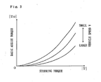
- the product of the basic assist current io and the basic vehicle speed gain Gv corresponds to the basic assist torque. As shown in Fig.
- the magnitude of the basic assist torque To increases up to a set upper limit value as the magnitude of the steering torque T increases, and if the steering torque T is fixed, the magnitude of the basic assist torque To increases as the vehicle speed V decreases.
- the relationship between the steering torque T and the basic assist current io and the relationship between the vehicle speed V and the basic vehicle speed gain Gv are stored, that is to say, the relationship between the steering torque T and the basic assist torque To is stored.
- the steering angle ⁇ is calculated in a calculating part 43.
- the sign of the steering angle ⁇ is positive in cases where the vehicle is oriented in either left or right direction, and the sign of the steering angle ⁇ is negative in cases where the vehicle is oriented in the opposite direction.
- ta is the temperature of the motor 10 as detected by the temperature detection part 29, to is a preset reference temperature
- Ro is the internal resistance of the motor 10 at the reference temperature to
- ⁇ is the resistance temperature coefficient at the reference temperature.
- the magnitude of the steering torque T is equal to or less than a set value T' because of no substantial steering operation being performed
- the magnitude of the yaw rate ⁇ is equal to or less than a set value ⁇ ' because of no substantial turning of the vehicle occurring
- the vehicle speed V is equal to or greater than a set value V' because of the vehicle being not stopped continues for a set time t' or longer, then it is judged that the vehicle is in a state of straight forward motion.
- the relative steering angles ⁇ r at any times when the vehicle is judged to be in a state of straight forward motion are taken as the reference steering angles, and a mean reference steering angle is determined by dividing the frequency of judgments that the vehicle is in a state of straight forward motion into total of the reference steering angles.
- ⁇ rm is the reference steering angle determined at the time when the mth judgment that the vehicle is in a state of straight forward motion is performed
- ⁇ m is the mean reference steering angle determined at the time when the mth judgment that the vehicle is in a state of straight forward motion is performed
- a judging part 44 it is judged whether or not return steering operation toward the straight forward steering position is being performed, and in cases where the return steering operation is being performed, the determined steering angle ⁇ is input into a calculating part 45, while in cases where the return steering operation is not being performed, the steering angle ⁇ which is input into the calculating part 45 is set at zero.
- the return steering operation is performed if the positive or negative sign of the steering angle variation ratio does not agree with the positive or negative sign of the detected steering torque T.
- a set relationship between the steering angle ⁇ and correction current i1 which is the output correction value for the motor 10 is stored in the form of, for example, a table or calculation formula, and the correction current i1 is calculated on the basis of this stored relationship and the determined steering angle ⁇ .
- the correction current i1 is zero.
- the relationship between the steering angle ⁇ and the correction current i1 is set so that the correction current i1 has an inverse correlation with the steering angle ⁇ .
- a calculating part 46 the relationship between the frequency m of judgments that the vehicle is in a state of straight forward motion and the midpoint judgment gain Gm is stored in the form of, for example, a table or calculation formula, and the midpoint judgment gain Gm corresponding to the frequency m of judgment is calculated.
- the midpoint judgment gain Gm has a positive correlation with the frequency m of judgments, as shown for example in the calculating part 46 of Fig. 2, this gain is set at zero until the frequency m of judgments reaches a first set value m1. Subsequently, this gain increases in proportion to the frequency m of judgments, and is set at a fixed value when the frequency m of judgments is reached a second set value m2.
- the control device 20 determines the sum of a value obtained by multiplying the correction current i1 by the midpoint judgment gain Gm in a multiplying part 47 and a value obtained by multiplying the basic assist current io by the basic vehicle speed gain Gv in a multiplying part 49 as the target driving current i* of the motor 10.
- the steering assist force is provided by controlling the motor 10 with feedback control so that the deviation between the target driving current i* and the determined driving current i is reduced.
- the output of the motor 10 is corrected in accordance with the correction current i1 determined on the basis of the determined steering angle ⁇ , and this correction current i1 is altered so as to have a positive correlation with the frequency m of judgments, furthermore the correction current i1 has an inverse correlation with the steering angle ⁇ when the return steering operation is being performed.
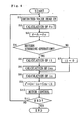
- step S1 the detected values detected by the respective sensors are read in (step S1), and the steering angle midpoint ⁇ o is calculated (step S2).
- step S2 the internal resistance R of the motor 10 is determined (step S101)
- step S102 the counter electromotive force Ea of the motor 10 is determined (step S102)
- step S103 the relative steering angle ⁇ r is determined (step S103).
- an initial set value can be used as an initial relative steering angle and an initial steering angle midpoint at the time of initiation of control, e. g., this value is set at zero.
- step S104 it is judged whether or not the magnitude of the steering torque T is equal to or less than the set value T' (step S104). If this steering torque T is equal to or less than the set value T' (S104: YES), it is judged whether or not the magnitude of the yaw rate ⁇ is equal to or less than the set value ⁇ ' (step S105). If this yaw rate ⁇ is equal to or less than the set value ⁇ ' (S105: YES), it is judged whether or not the vehicle speed V is equal to or greater than the set value V' (step S106).
- step S107 If the vehicle speed V is equal to or greater than the set value V' (S106: YES), the timer is switched on (step S107), and it is judged whether or not a set time t' or longer has elapsed (step S108). If this set time t' or longer has elapsed (S108: YES), the frequency m of judgments that the vehicle is in a state of straight forward motion is increased by 1 (step S109); subsequently, the steering angle midpoint ⁇ o is determined (step S110), and the processing is returned. In cases where the judgment is negative in any of the step S104, S105 or S106, the timer is reset (step S111), and the processing is returned.
- step S108 In cases where the judgment is negative in step S108 (S108: NO), the processing is returned without resetting the timer. Following the calculation of the steering angle midpoint ⁇ o, the steering angle ⁇ is calculated (step S3). Next, it is judged whether or not the return steering operation is being performed (step S4), and in cases where the return steering operation is being performed (S4: YES), the correction current i1 corresponding to the determined steering angle ⁇ is calculated (step S5), and the midpoint judgment gain Gm corresponding to the frequency m of judgments that the vehicle is in a state of straight forward motion is calculated (step S6). In cases where the return steering operation is not being performed (S4: NO), the correction current i1 is set at zero (step S7).
- the precision of the mean reference steering angle used as the steering angle midpoint ⁇ o increases with the increase of the frequency m of judgments that the vehicle is in a state of straight forward motion. Accordingly, the precision of the correction current i1 determined on the basis of the steering angle ⁇ which is determined with taking the mean reference steering angle as the steering angle midpoint ⁇ o increases with the increase of the frequency m of judgments.
- the correction current i1 is altered so as to have a positive correlation with the frequency m of judgments, it is possible to reduce the amount of output correction of the motor 10 so that the precision has no effect and control can be quickly initiated in cases where the frequency m of judgments is small and the precision of the correction current i1 is low, and it is also possible to increase the amount of output correction of the motor 10 so that control can be performed with good precision in cases where the frequency m of judgments increases and the precision of the correction current i1 is increased Furthermore, the magnitude of the correction current i1 is large as the steering angle ⁇ is large when the return steering operation is being performed, so that the effect of the steering reaction force which is applied from the road surface via the vehicle wheels 3 can be reduced.
- the present invention is not limited to the abovementioned embodiment.
- the vehicle can be judged to be in a state of straight forward motion if a state in which the magnitude of the steering angle variation rate is equal to or less than a set value because of no substantial steering operation being performed, the magnitude of the lateral acceleration is equal to or less than a set value because of no substantial turning of the vehicle occurring, and the vehicle speed is equal to or greater than a set value because of the vehicle being not stopped continues for a set period of time or longer.
- the relative steering angle can be determined by an angle sensor instead of being determined by calculation; as a result, the steering angle from the steering angle midpoint can be precisely determined even if the precision of the angle sensor is deteriorated due to lapse of time and others.
- the output correction value of the motor is not limited to the value which is determined on the basis of the steering angle alone, for example, this value can vary in accordance with the steering angle variation rate, steering angle variation acceleration or the like so that the effects of inertia of the motor and disturbance can be compensated for.
- the mechanism which transmits the rotation of the steering wheel to the vehicle wheels so that the steering angle varies is not limited to the abovementioned embodiment; this can also be a system which transmits the rotation of the steering wheel to the vehicle wheels via the steering shaft and a link mechanism other than the rack and pinion mechanism. Furthermore, as long as the mechanism which transmits the output of the motor for generating steering assist force to the steering system is capable of providing steering assist force, this mechanism is not limited to the abovementioned embodiment; for example, the steering assist force can also be provided by driving a ball nut screwed onto a ball screw integrated with the rack by means of the output of the motor.
Claims (2)
- Elektrische Servolenkvorrichtung, die folgendes aufweist:einen Motor (10), der eine Lenkhilfskraft gemäß einem Basis-Hilfsmoment erzeugt;einen Bestimmungsteil (20), der einen relativen Lenkwinkel (δm) bei jedem von n Zyklen von Berechnungen aus der Beziehung δm = δm-1 + ωn x t1 bestimmt, wobei n die tatsächliche Anzahl der Zyklen von Berechnungen ist, t1 der Zyklus einer Berechnung im Bestimmungsteil (20) und δn eine Lenkwinkel-Veränderungsrate ist, die proportional zu einer elektromotorischen Gegenkraft (Ea) des Motors (10) ist;einen Beurteilungsteil (20), der beurteilt, ob ein Fahrzeug in einem Zustand einer Geradeausbewegung ist oder nicht;einen Bestimmungsteil (20), der einen mittleren Referenz-Lenkwinkel (δm) durch Teilen einer Gesamtheit der relativen Lenkwinkel (δr), die bestimmt werden, wenn beurteilt wird, dass das Fahrzeug in einem Zustand einer Geradeausbewegung ist, durch die Anzahl von Beurteilungen, dass das Fahrzeug in einem Zustand einer Geradeausbewegung ist, bestimmt;einen Bestimmungsteil (20), der einen Lenkwinkel (δ) durch Subtrahieren eines Lenkwinkel-Mittelpunkts (δ0) von dem relativen Lenkwinkel (δr) bestimmt, während der mittlere Referenz-Lenkwinkel (δm) als der Lenkwinkel-Mittelpunkt (δ0) genommen wird;einen Korrekturteil (20), der die Ausgabe des Motors (10) entsprechend dem Basis-Hilfsmoment gemäß einem Ausgabekorrekturwert korrigiert, der auf der Basis des bestimmten Lenkwinkels (δ) bestimmt ist; undeinen Änderungsteil (20), der den Ausgabekorrekturwert ändert, so dass dieser Wert eine positive Korrelation mit der Anzahl von Beurteilungen hat, dass das Fahrzeug in dem Zustand einer Geradeausbewegung ist.
- Elektrische Servolenkvorrichtung nach Anspruch 1, die weiterhin folgendes aufweist:einen Sensor (22), der ein Lenkmoment bestimmt;eine Steuerung (20), die den Motor (10) so steuert, dass eine Lenkhilfskraft entsprechend dem bestimmten Lenkmoment erzeugt wird; undeinen Beurteilungsteil (20), der beurteilt, ob eine Rückstell-Lenkoperation in Richtung zu der Geradeaus-Lenkposition durchgeführt wird oder nicht;wobei der Ausgabekorrekturwert eine inverse Korrelation zu dem bestimmten Lenkwinkel (δ) hat, wenn die Rückstell-Lenkoperation durchgeführt wird.
Applications Claiming Priority (1)
| Application Number | Priority Date | Filing Date | Title |
|---|---|---|---|
| JP2004305824 | 2004-10-20 |
Publications (2)
| Publication Number | Publication Date |
|---|---|
| EP1650105A1 EP1650105A1 (de) | 2006-04-26 |
| EP1650105B1 true EP1650105B1 (de) | 2007-12-12 |
Family
ID=35610070
Family Applications (1)
| Application Number | Title | Priority Date | Filing Date |
|---|---|---|---|
| EP05022641A Active EP1650105B1 (de) | 2004-10-20 | 2005-10-17 | Elektrische Servolenkung |
Country Status (3)
| Country | Link |
|---|---|
| US (1) | US7512468B2 (de) |
| EP (1) | EP1650105B1 (de) |
| DE (1) | DE602005003753T2 (de) |
Families Citing this family (13)
| Publication number | Priority date | Publication date | Assignee | Title |
|---|---|---|---|---|
| JP4957071B2 (ja) * | 2006-05-08 | 2012-06-20 | 日本精工株式会社 | 電動パワーステアリング装置の制御装置 |
| JP5088531B2 (ja) * | 2006-12-21 | 2012-12-05 | 株式会社ジェイテクト | 車両用操舵装置 |
| JP4603593B2 (ja) * | 2008-04-23 | 2010-12-22 | 本田技研工業株式会社 | 電動パワーステアリング装置 |
| US8428822B2 (en) * | 2009-03-13 | 2013-04-23 | Honda Motor Co., Ltd. | Method of determining a steering angle in a motor vehicle |
| US8764523B2 (en) | 2009-10-08 | 2014-07-01 | Wolf-Tec, Inc. | Macerator having automated roller spacing control |
| JP5772359B2 (ja) * | 2011-08-02 | 2015-09-02 | 株式会社ジェイテクト | モータ制御装置及び電動パワーステアリング装置 |
| JP2014230681A (ja) * | 2013-05-30 | 2014-12-11 | 船井電機株式会社 | パワーアシスト装置及び歩行補助車 |
| JP5819358B2 (ja) * | 2013-07-16 | 2015-11-24 | 本田技研工業株式会社 | 車両用操舵装置 |
| DE102017103034B4 (de) * | 2016-02-16 | 2022-02-10 | Steering Solutions Ip Holding Corporation | Lenkungssystem zum Detektieren von Bewegungszuständen eines Fahrzeugs |
| JP6747367B2 (ja) * | 2017-04-18 | 2020-08-26 | 株式会社デンソー | 舵角検出装置、および、これを用いた電動パワーステアリング装置 |
| US10800443B2 (en) | 2017-09-21 | 2020-10-13 | Steering Solutions Ip Holding Corporation | Catch motor torque generation in steer by wire system |
| US11377140B2 (en) | 2017-12-07 | 2022-07-05 | Steering Solutions Ip Holding Corporation | Notification for rack limiting conditions for steer by wire steering systems |
| US10906581B2 (en) | 2017-12-07 | 2021-02-02 | Steering Solutions Ip Holding Corporation | Rack-limiting condition detection and the corresponding steering wheel torque feedback for steer by wire steering systems |
Family Cites Families (7)
| Publication number | Priority date | Publication date | Assignee | Title |
|---|---|---|---|---|
| JPH01257671A (ja) * | 1988-04-06 | 1989-10-13 | Fuji Heavy Ind Ltd | 自動車用電動式パワステアリング装置の制御装置 |
| JP2781854B2 (ja) * | 1989-12-20 | 1998-07-30 | 光洋精工株式会社 | 動力舵取装置 |
| JP2852640B2 (ja) * | 1996-04-12 | 1999-02-03 | 光洋精工株式会社 | 電動パワーステアリング装置 |
| US6913103B2 (en) * | 2000-02-03 | 2005-07-05 | Yanmar Co., Ltd. | Hydraulically driven traveling vehicle |
| JP4670161B2 (ja) * | 2000-07-13 | 2011-04-13 | マツダ株式会社 | 自動車の電動パワーステアリング装置 |
| JP3947014B2 (ja) * | 2002-01-25 | 2007-07-18 | 株式会社ジェイテクト | 電動パワーステアリング装置 |
| JP2004203366A (ja) * | 2002-10-31 | 2004-07-22 | Koyo Seiko Co Ltd | 電動パワーステアリング装置 |
-
2005
- 2005-10-17 DE DE602005003753T patent/DE602005003753T2/de active Active
- 2005-10-17 EP EP05022641A patent/EP1650105B1/de active Active
- 2005-10-19 US US11/255,223 patent/US7512468B2/en not_active Expired - Fee Related
Also Published As
| Publication number | Publication date |
|---|---|
| DE602005003753D1 (de) | 2008-01-24 |
| US7512468B2 (en) | 2009-03-31 |
| EP1650105A1 (de) | 2006-04-26 |
| US20060085113A1 (en) | 2006-04-20 |
| DE602005003753T2 (de) | 2008-04-10 |
Similar Documents
| Publication | Publication Date | Title |
|---|---|---|
| EP1650105B1 (de) | Elektrische Servolenkung | |
| EP3213979B1 (de) | Lenksteuerungssystem | |
| US7885742B2 (en) | Steering device of vehicle | |
| US7584819B2 (en) | Vehicle steering system | |
| US7177745B2 (en) | Steering control apparatus | |
| EP3072784B1 (de) | Motorgetriebene servolenkvorrichtung | |
| US20120041645A1 (en) | Steering control apparatus for vehicle and steering control method | |
| EP2792576A1 (de) | Elektrische servolenkvorrichtung | |
| US8676441B2 (en) | Steering support device | |
| US8823305B2 (en) | Electric power steering system | |
| US20170334480A1 (en) | Electric power steering device | |
| JP6187713B2 (ja) | 電動パワーステアリング装置 | |
| JP2012101674A (ja) | 電動パワーステアリング装置 | |
| CN113661113B (zh) | 用于控制线控转向系统的方法和用于机动车辆的线控转向系统 | |
| US7503421B2 (en) | Electric power steering apparatus | |
| EP1213204B1 (de) | Lenkung und Vorrichtung zum Berechnen der inneren Verluste für diese Lenkung | |
| EP2639137B1 (de) | Fahrzeuglenkungssteuerungssystem | |
| CN110337400A (zh) | 用于以位置控制和柱扭矩控制模式辅助机动车辆转向的机电式机动车辆动力转向机构 | |
| EP1415891B1 (de) | Elektrische Servolenkung und Verfahren zur Steuerung dafür | |
| JP4928581B2 (ja) | センサの中点補正方法 | |
| JP4683210B2 (ja) | 電動パワーステアリング装置 | |
| US11679805B2 (en) | Traction steer mitigation through CVR gain scalars | |
| JPH08216910A (ja) | 車両の操舵制御装置 | |
| JP2006076484A (ja) | 電動パワーステアリング装置の制御装置 | |
| JPH06179375A (ja) | 車両の舵角制御装置 |
Legal Events
| Date | Code | Title | Description |
|---|---|---|---|
| PUAI | Public reference made under article 153(3) epc to a published international application that has entered the european phase |
Free format text: ORIGINAL CODE: 0009012 |
|
| AK | Designated contracting states |
Kind code of ref document: A1 Designated state(s): AT BE BG CH CY CZ DE DK EE ES FI FR GB GR HU IE IS IT LI LT LU LV MC NL PL PT RO SE SI SK TR |
|
| AX | Request for extension of the european patent |
Extension state: AL BA HR MK YU |
|
| 17P | Request for examination filed |
Effective date: 20060306 |
|
| RAP1 | Party data changed (applicant data changed or rights of an application transferred) |
Owner name: JTEKT CORPORATION Owner name: FAVESS CO., LTD. Owner name: TOYODA KOKI KABUSHIKI KAISHA |
|
| 17Q | First examination report despatched |
Effective date: 20060823 |
|
| RAP1 | Party data changed (applicant data changed or rights of an application transferred) |
Owner name: JTEKT CORPORATION |
|
| AKX | Designation fees paid |
Designated state(s): DE FR GB |
|
| 17Q | First examination report despatched |
Effective date: 20060823 |
|
| GRAP | Despatch of communication of intention to grant a patent |
Free format text: ORIGINAL CODE: EPIDOSNIGR1 |
|
| GRAS | Grant fee paid |
Free format text: ORIGINAL CODE: EPIDOSNIGR3 |
|
| GRAA | (expected) grant |
Free format text: ORIGINAL CODE: 0009210 |
|
| AK | Designated contracting states |
Kind code of ref document: B1 Designated state(s): DE FR GB |
|
| REG | Reference to a national code |
Ref country code: GB Ref legal event code: FG4D |
|
| REF | Corresponds to: |
Ref document number: 602005003753 Country of ref document: DE Date of ref document: 20080124 Kind code of ref document: P |
|
| ET | Fr: translation filed | ||
| PLBE | No opposition filed within time limit |
Free format text: ORIGINAL CODE: 0009261 |
|
| STAA | Information on the status of an ep patent application or granted ep patent |
Free format text: STATUS: NO OPPOSITION FILED WITHIN TIME LIMIT |
|
| 26N | No opposition filed |
Effective date: 20080915 |
|
| PG25 | Lapsed in a contracting state [announced via postgrant information from national office to epo] |
Ref country code: GB Free format text: LAPSE BECAUSE OF NON-PAYMENT OF DUE FEES Effective date: 20091017 |
|
| REG | Reference to a national code |
Ref country code: FR Ref legal event code: PLFP Year of fee payment: 12 |
|
| REG | Reference to a national code |
Ref country code: FR Ref legal event code: PLFP Year of fee payment: 13 |
|
| REG | Reference to a national code |
Ref country code: FR Ref legal event code: PLFP Year of fee payment: 14 |
|
| PGFP | Annual fee paid to national office [announced via postgrant information from national office to epo] |
Ref country code: FR Payment date: 20230911 Year of fee payment: 19 |
|
| PGFP | Annual fee paid to national office [announced via postgrant information from national office to epo] |
Ref country code: DE Payment date: 20230830 Year of fee payment: 19 |
|
| REG | Reference to a national code |
Ref country code: DE Ref legal event code: R082 Ref document number: 602005003753 Country of ref document: DE Representative=s name: PUSCHMANN BORCHERT KAISER KLETTNER PATENTANWAE, DE |