EP1649736B1 - Dispositif de refroidissement d'un composant electronique, en particulier d'un microprocesseur - Google Patents
Dispositif de refroidissement d'un composant electronique, en particulier d'un microprocesseur Download PDFInfo
- Publication number
- EP1649736B1 EP1649736B1 EP04738807A EP04738807A EP1649736B1 EP 1649736 B1 EP1649736 B1 EP 1649736B1 EP 04738807 A EP04738807 A EP 04738807A EP 04738807 A EP04738807 A EP 04738807A EP 1649736 B1 EP1649736 B1 EP 1649736B1
- Authority
- EP
- European Patent Office
- Prior art keywords
- heat sink
- sink part
- electronic component
- rack
- heat
- Prior art date
- Legal status (The legal status is an assumption and is not a legal conclusion. Google has not performed a legal analysis and makes no representation as to the accuracy of the status listed.)
- Active
Links
Images


Classifications
-
- H—ELECTRICITY
- H01—ELECTRIC ELEMENTS
- H01L—SEMICONDUCTOR DEVICES NOT COVERED BY CLASS H10
- H01L23/00—Details of semiconductor or other solid state devices
- H01L23/34—Arrangements for cooling, heating, ventilating or temperature compensation ; Temperature sensing arrangements
- H01L23/46—Arrangements for cooling, heating, ventilating or temperature compensation ; Temperature sensing arrangements involving the transfer of heat by flowing fluids
- H01L23/473—Arrangements for cooling, heating, ventilating or temperature compensation ; Temperature sensing arrangements involving the transfer of heat by flowing fluids by flowing liquids
-
- H—ELECTRICITY
- H01—ELECTRIC ELEMENTS
- H01L—SEMICONDUCTOR DEVICES NOT COVERED BY CLASS H10
- H01L23/00—Details of semiconductor or other solid state devices
- H01L23/34—Arrangements for cooling, heating, ventilating or temperature compensation ; Temperature sensing arrangements
- H01L23/42—Fillings or auxiliary members in containers or encapsulations selected or arranged to facilitate heating or cooling
- H01L23/427—Cooling by change of state, e.g. use of heat pipes
-
- H—ELECTRICITY
- H05—ELECTRIC TECHNIQUES NOT OTHERWISE PROVIDED FOR
- H05K—PRINTED CIRCUITS; CASINGS OR CONSTRUCTIONAL DETAILS OF ELECTRIC APPARATUS; MANUFACTURE OF ASSEMBLAGES OF ELECTRICAL COMPONENTS
- H05K7/00—Constructional details common to different types of electric apparatus
- H05K7/20—Modifications to facilitate cooling, ventilating, or heating
- H05K7/20009—Modifications to facilitate cooling, ventilating, or heating using a gaseous coolant in electronic enclosures
-
- H—ELECTRICITY
- H01—ELECTRIC ELEMENTS
- H01L—SEMICONDUCTOR DEVICES NOT COVERED BY CLASS H10
- H01L2924/00—Indexing scheme for arrangements or methods for connecting or disconnecting semiconductor or solid-state bodies as covered by H01L24/00
- H01L2924/0001—Technical content checked by a classifier
- H01L2924/0002—Not covered by any one of groups H01L24/00, H01L24/00 and H01L2224/00
Definitions
- the invention relates to a cooling device for an electronic component, in particular for a microprocessor, with the features of the preamble of claim 1. Furthermore, the invention relates to a rack for receiving a plurality of electronic components, such as servers for data processing systems, with the features of claim 8.
- the individual electronic components such as a plurality of servers, are housed in cabinets or racks to ensure an orderly installation and cabling of the individual components.
- air conditioning is carried out in racks or cabinets for such electronic components, ie the power loss generated by the components in the form of heat energy is dissipated by suitable means.
- rack is used both for closed cabinets and for open racks in which the individual components are accommodated.
- the power loss is mainly generated by electronic components of the individual components. In modern data processing systems, the majority of the power loss of microprocessors is generated. The power loss of a processor has been on the order of about 100 W.
- a power loss in this area was with processor fans, ie a combination of a metallic heat sink and a fan module, from the processor into the interior of the housing of the server or the electronic component of There it is discharged into the interior of the (preferably closed) rack and then to the room air surrounding the rack.
- processor fans ie a combination of a metallic heat sink and a fan module
- the power loss in the form of heat which is delivered by other modules and components of the individual electronic components, such as power supplies, drives, etc., that is, of a variety of individual electronic components, which in itself deliver a relatively low power loss, so that a separate cooling of these electronic components is not worthwhile, wherein
- these low power losses can also add up to values of 100 to 150 W and more per electronic component.
- a cooling device for electronic devices is known.
- the heat exchanger may have a rib-shaped surface, wherein a second heat exchanger is attached to the heat exchanger.
- channels may be provided within the body of the heat exchanger.
- the US 5,982,616 discloses a cooling system for electronic devices. Again, two separate heat sinks are again provided for simplified attachment.
- Cooling is known for a motherboard and other elements to be cooled.
- a heat transfer is realized via a connection structure, which is attached via a thermally and mechanically detachable coupling, with the aid of cold water.
- the present invention seeks to provide a cooling device for an electronic component, in particular for a microprocessor, in which the actual heat sink easily, quickly and without the risk of damage or destruction of the electronic component to be cooled mountable and is removable. Furthermore, the invention has for its object to provide a rack for receiving a plurality of electronic components, such as servers for data processing systems, using such cooling devices, which are cooled by a liquid heat transfer medium.
- the invention is based on the finding that by means of a heat sink, which comprises a first heat sink part, which is designed for connection to the electronic component, and a second heat sink part, which is detachably connected to the first heat sink part such that a low heat transfer resistance is given , Wherein at least the major part of the heat loss is discharged through the second heat sink part to a cooling medium, the advantage is achieved that for the first time installation of the cooling device, only the first heat sink part must be thermally coupled and fixed once with the electronic component to be cooled. This can already be done by the manufacturer of the electronic component factory.
- the first heat sink part can also be mounted on the latter by the manufacturer of the electronic component to be cooled.
- the first heat sink part may also be formed integrally with the housing of the electronic component, in particular inextricably connected thereto.
- the second heat sink part can then be easily thermally conductively connected without the risk of damaging the electronic component with the first heat sink part.
- the second heat sink part can then be easily separated again, if necessary, from the first heat sink part.
- the second heat sink is designed as a flowed through by liquid cooling medium heat sink.
- the second heat sink part has at least one channel through which a liquid cooling medium, for example water, flows.
- an inlet connection and a return connection are provided on the second heat sink part, which are connected to the at least one channel.
- the first heat sink part comprises a contact surface for thermal connection to the second heat sink part, which has a structure for enlarging the contact surface, wherein the contact surface of the first heat sink part cooperates with a complementary formed contact surface of the second heat sink part.
- the area of the thermal interface between the first and second cooling body part may be larger than the area of the thermal interface between the electronic component to be cooled and the first cooling body part.
- the structure for increasing the contact area between the first and second heat sink part is provided at least in that (horizontal cross-sectional) region of the first heat sink part, in which the first heat sink part is in contact with the electronic component to be cooled, ie in the region of the so-called hot spots (seen in plan view of the device or the cooling device).
- the structures are formed as ribs with oblique, preferably flat flanks and preferably have a trapezoidal cross-section.
- Such a structure has the advantage that for the realization of the second heat sink simple, high-precision and inexpensive to produce extruded profiles can be used.
- the flank angle can be chosen so that a high surface pressure between the complementary structures of the first and second already by relatively low contact forces acting on the second heat sink member in the direction of the first heat sink part Heat sink part arise and thus a low heat transfer resistance is ensured.
- this advantage can be achieved not only with complementary rib-shaped structures, but more generally with structures having partial surfaces which are inclined at a suitable angle to the direction of the contact force acting on the first heat sink part in the direction of the second heat sink part.
- a "hedgehog structure" may be used in which a plurality of serrated extensions on the underside of the second heat sink member cooperate with a corresponding complementary structure on the surface of the first heat sink member.
- the serrated projections have correspondingly inclined outer surfaces.
- channels for the cooling medium are provided at least in ribs of the contact surface of the second heat sink part. This results in the advantage that the one or more streams of the cooling medium are close to the surface of the component to be cooled.
- the channels may be arranged in the respective ribs such that, at least in substantial regions of these ribs, which are in contact with corresponding complexary ribs of the first heat sink part, the walls provide relatively thin walls.
- These walls can be dimensioned in terms of their thickness, depending on the material and the contact forces so that they allow slight deformations under the action of the contact forces, so as flat as possible concerns the outer sides of these walls to the complementary ribs of the first heat sink part and thus a good heat transfer guarantee.
- the second part of the cooling body in the region of the inlet connection and / or the return connection can have a collecting chamber, from which several channels branch for the cooling medium or into it lead.
- a good heat transfer to the liquid cooling medium is achieved because a larger surface can be reached than in a single, possibly larger in cross-section channel.
- the central region of the second heat sink can be realized with an extruded profile, which is connected on opposite sides in each case with a part forming the plenum chamber and having the relevant inflow or return connection.
- the second heat sink part may have larger dimensions than the first heat sink part in at least one direction with respect to the contact surface with the first heat sink part. This results in the advantage that the position of the first heat sink portion relative to the second heat sink portion during assembly of the second heat sink portion on the first heat sink body is not critical. For example, in a configuration of the contact surface increasing structure in the form of ribs, the seconddegroperteil over the first. Heat sink part easily be moved slightly.
- the second heat sink part may be formed such that by means of the coolant flow through the at least one channel in the contact surface with the first heat sink part, a heat dissipation that is substantially uniform relative to the contact surface is possible.
- a heat dissipation that is substantially uniform relative to the contact surface is possible.
- they can be formed over the entire actual contact surface with the first heat sink part. Possibly. existing collection chambers at one or both ends of this central region may then lie outside of this, relative to the actual contact surface.
- It can also be formed only one or more cooling fins, each with at least one channel, which are located in the region of the so-called "hot spots" of the electronic component to be cooled.
- the first heat sink part may be formed as a heat pipe.
- a heat pipe transports by means of an evacuated vessel, e.g. a metal pipe, directed heat from one point to another.
- an evacuated vessel e.g. a metal pipe
- the metal tube itself is a relatively small volume of liquid, which may consist predominantly of distilled water (the remaining portion then consists of special ingredients that optimize the heat transfer).
- the liquid is under a low pressure, so that an evaporation temperature of about 30 degrees Celsius occurs. Only when the heat pipe is supplied with heat at one end, the water evaporates and transports the heat energy very low loss to the cold end. There is a condensation of the steam and, accordingly, a release of heat.
- the condensed liquid returns to the lower part of the vessel, closing the circuit.
- the dissipated heat can be transported extremely lossless to a point where they pass over by means of the second heat sink part to the cooling medium and can be finally dissipated.
- the interface to the second heat sink part can thus be displaced to a location outside of a housing, wherein the relevant end of the heat pipe can protrude through an opening in the housing. When replacing the entire component then not even the housing must be opened. It is only necessary to detach the second heat sink part from the first heat sink part.
- An inventive rack for holding a plurality of electronic components is designed for cooling of electronic components in the individual electronic components, wherein a plurality of cooling devices are provided according to the invention with a flowed through by a liquid cooling medium second heat sink part.
- the second heat sink parts of the cooling devices may be connected with their inlet and outlet connections with one or more central coolant reservoirs or one or more central heat exchangers, through which the cooling medium heat is removed.
- the one or more central coolant reservoirs or the one or more central heat exchangers may be disposed in or on the rack.
- a line system may be provided which connects the inlet connections of the cooling devices with one or more central inlet connections of the rack and the return connections of the cooling devices with one or more central return connections of the rack.
- At least one fixed, preferably rigid inlet riser is provided in the rack, which has a plurality of connections for preferably flexible connection lines from one connection to one inlet connection of a second cooling body part of a cooling device.
- preferably rigid return riser is provided, which has a plurality of connections for preferably flexible connecting lines of a respective connection to a return port of a second heat sink part of a cooling device.
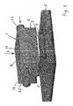
- Fig. 1 shows in perspective view schematically a cooling device 1, which is mounted on an electronic component 3, for example a microprocessor.
- the microprocessor 3 is in turn arranged on an only indicated board 5, on which, of course, further components or assemblies may be provided.
- the board 5 may be, for example, a mainboard of a server.
- the cooling device 1 comprises a first heat sink part 7 made of a good heat-conducting material, such as aluminum or copper, which is thermally conductively connected directly to the housing or a thermal interface of the electronic component to be cooled. This may be, for example, a heat spreader of a microprocessor or of the electronic component 3.
- the first cooling body part 7 has, on its side facing away from the component 3, a structure in the form of ribs 11, which, as in FIG Fig. 2 represented, may have a trapezoidal cross-section.
- a second heat sink part 9 made of a good heat-conducting material, such as aluminum or copper, arranged and thermal well connected with this.
- the second cooling body part 9 is provided on its underside with a complementary structure in the form of ribs 13.
- the ribs 13 pass channels 15 for a liquid, the channels 15 by flowing cooling medium (not shown), which removes the power generated by the electronic component 3 in the form of heat dissipation.
- the arrangement of the channels 15 in the ribs offers the advantage that with correspondingly thin walls of the ribs 15, the cooling medium can be guided close to the surface of the component 3, in particular also between the ribs 11 of the first cooling body part 7.
- the trapezoidal design of the ribs 11 and 13 also offer the advantage that with a small contact force F acting on the second heat sink part 9 in the direction of the first heat sink part 7, a high contact pressure of the side surfaces of the trapezoidal ribs 11 and 13 generates and consequently a good thermal coupling can be guaranteed.
- the ribs 13 having central portion 17 of the second heat sink part 9 is in its extension (parallel to the surface of the device 3) at least as large as the extension of the ribs 11 having surface of the first heat sink part 7.
- a substantially constant heat transfer resistance in the contact surface of the two heat sink parts 7 and 9 - at least along lines parallel to the longitudinal direction of the ribs - can be achieved.
- Such a trained middle region 17 also has the advantage that it can be made from a highly accurate and cost-effective extruded profile. This also applies to the first heat sink part 7.
- the in the Fig. 1 or 2 identifiable, respectively at the two ends of the central region of the second heat sink portion 9 subsequent end portion 19 and 21, may be formed in terms of the outer contour identical to the central region 17.
- a collection chamber (not shown) is provided, which is in each case connected to the channels 15.
- the areas 17, 19, 21 may of course be formed in one piece.
- an end region 19, 21 can be produced in that in the end regions of a corresponding extruded profile, the inner walls between the channels 15 are partially or completely removed from both sides, for example milled out. The mutual openings of the extruded profile can then be closed with corresponding covers, for example by soldering or the like.
- an inlet connection 23 for a feed line and a return connection 25 for a return line are provided.
- the cooling medium is supplied at the given (sufficiently low) temperature with sufficient for the cooling mass flow through the supply line of the cooling device 1 and discharged via the return line.
- the assembly of the first heat sink part 7 on the electronic component 3 can be carried out in a conventional manner by means of a suitable screw connection or by means of clamps or other suitable connection means.
- the first heat sink part for this purpose for example, have laterally arranged fastening means, which can also protrude laterally beyond the surface of the component 3.
- the fixing of the first heat sink part 7 on the component 3 may be compared with the circuit board 5 or a housing, not shown, of an electronic component 27 (FIG. Fig. 3 ), in which the circuit board 3 is arranged.
- the first heat sink part 7 may also be permanently connected to the component 3, for example by gluing with a thermally conductive adhesive, or even integrally formed with the housing of the component 7.
- connection of the second heat sink part 9 with the first heat sink part 7 can be done by means of suitable, but in any case releasable connection means, for example by screwing, by means of Fixierklammern or the like.
- the pressing of the heat sink part 9 on the heat sink member 7 with sufficient pressure can also by the placement and pressing of a housing part of a housing of a Electronic component 27 take place, in which the board 5 is included with the component to be cooled 3 and the cooling device 1 arranged thereon.
- This special design of the cooling device has the advantage that the second cooling body part 9 acting as the actual cooling body can be detached from the first cooling body part 7, without the mechanically sensitive thermal interface between the component 3 to be cooled and the first cooling body part having to be solved.
- Fig. 3 schematically shows a rack 29 in side view, in which a plurality of electronic components 27, such as servers for a larger computer system, can be included. For the sake of simplicity have been in Fig. 3 only two electronic components 27 located.
- Each of the electronic components may comprise one or more components 3 to be cooled, which are cooled by a cooling device 1 according to the invention.
- a cooling device 1 the rest of the heat generated by an electronic component 27 can be discharged in a conventional manner by means of fans in the interior of the rack 29 and from there to the environment.
- a line system may be arranged in the rack, which feeds the cooling medium from a central inlet connection 31 of the rack 29 to the inlet connections 23 of the individual cooling devices 1 and from the return connections 25 of the individual cooling devices 1 to a central return connection 33 of the rack 29.
- the cooling medium can be supplied to the central inlet connection 31 of the rack 29 by a central cooling device (not shown) and returned to the central return connection 33 of the rack 29.
- cooling devices 1 it is not absolutely necessary to switch all cooling devices 1 individually in parallel between the central inlet and the central return of the rack 29. Rather, several or all cooling devices 1 can be connected in series, if the temperature of the cooling medium after leaving the respective upstream cooling device 1 and the respective mass flow of the cooling medium allow this. In particular, in the event that several cooling devices 1 are provided in an electronic component, these cooling devices can be connected in series.
- the conduit system arranged in the rack can comprise an inlet riser 35, which guides the cooling medium from the central inlet connection 31 of the rack 29 to individual connections 39, which are each connected or connectable to an inlet connection 23 of a cooling device 1.
- the inlet riser may consist of a rigid conduit fixed to the rack.
- the lines between the terminals 39 and the respective inlet connection 23 of the respective cooling device 1 can be made flexible and, if necessary, have a sufficient excess length. This allows the extraction of the relevant electronic component 27 from the rack, for example, to open its housing and make repairs or replace components without the cooling device (s) 1 of the electronic component must be separated from the rest of the line system.
- an analogously formed return riser 37 may be provided, which also has connections 39 for connecting lines (not shown) between the return connections 25 of a respective cooling device 1 and the return riser 37.
- connection lines can also be flexible and have a sufficient excess length.
- the risers 35 and 37 are formed and connected so that for each electronic component 27 and arranged therein Cooling devices 1 (more precisely: for the partial flow of the coolant through the respective cooling devices) between the inlet port 31 and the return port 33 results in the same cable length. This will be at the in Fig.
- the "related" terminals 39 may be provided substantially at the same height, preferably in each case the height in which the electronic component 27 to be connected in the rack 29th is held.
- a central heat exchanger or a device for removing the heat energy absorbed by the cooling medium to the ambient air can also be provided in the rack itself.
- This embodiment can also central risers for the inlet and the return accordingly Fig. 3 exhibit.
- the connections for the central inlet and the central return must then not be led to the outside, but may be connected to the central heat exchanger or the device for removing the heat energy absorbed by the cooling medium.
- Such a designed rack has the advantage that an exchange of an entire electronic component is possible without the cooling device would have to be separated from the cooling circuit. It only needs the or each second heat sink part 9 of relevant first heat sink part 7 are solved.
- the replacement component which already has the preassembled first heat sink parts 7, can then simply be inserted into the rack. It is only necessary to connect the second heat sink parts 9 again to the relevant first heat sink parts 7. There is no danger that escapes by a separation of a line for the cooling medium at the coupling point cooling medium and thereby one or more electronic components are damaged. As a result, in particular a very secure hot plugging of electronic components can be guaranteed.
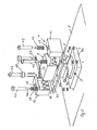
- Fig. 4 shows a further embodiment for the realization of a first cooling body part 7 and a second cooling body part 9 comprising cooling device 1.
- the second heat sink part 9 has the in Fig. 4
- This rib 13 engages in a formed between two upwardly extending ribs 11 of the first heat sink portion 7 recess and is formed to this substantially complementary.
- the second heat sink part 9 of the embodiment of a cooling device according to Fig. 4 comprises two channels 15 for guiding the cooling medium in the rib 13 of the second heat sink part 9. Instead, however, only a single, preferably centrally extending channel or multiple channels may be provided.
- the cross section of the first heat sink part 7 may also be interchanged with the cross section of the second heat sink part 9, with the exception of the channels 15 (embodiment not shown). That is, the first heat sink portion 7 may have a single upwardly extending projection 11 which engages a recess formed between two downwardly extending projections 13. In this case, one or more channels 15 may be formed in each of the projections 13 of the second heat sink part.
- first and second heat sink parts 7, 9 are advantageous to select the dimensions of the first and second heat sink parts 7, 9 larger in plan view than the surface to be cooled of the electronic component 3 to be cooled by a larger area for the heat transfer from the first heat sink part 7 to the second heat sink part 9 create and from the second heat sink part on the guided therein cooling medium.
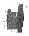
- Fig. 5 shows a further embodiment of a cooling device 1 in an exploded perspective view, which the embodiment according to the Fig. 1 and 2 similar. Compared to the embodiment of the Fig. 1 and 2 However, the supply and return ports 23, 25 led out at the end portions 23, 21 upwards.
- This component may comprise a housing 3a, on the upper side of the actually to be cooled area 3b of the semiconductor chip is provided.
- the first heat sink part 7 can act by means of a frame 41, whose parallel longitudinal sides 41a act with their lower sides on regions 7a of the first heat sink part 7, which extend in the direction transverse to the profile of the ribs 11 to the outside.
- a bore 45 is provided for a fastening screw 43.
- the fastening screws 43 pass through the holes 45 with their threaded portion 43a and receive in their shaft region between the upper side of the frame 41 and the underside of the respective screw head in each case a helical spring 47.
- the length of the shaft portion of the fastening screws 43 and the length and the spring constant of the coil springs 47 are coordinated so that when mounting the frame 41 for fixing the frame 41 on the first heat sink member 7 of the frame 41 by a bias of the coil springs 47 with a defined Spring force is pressed onto the electronic component 3 to be cooled.
- a thermal paste or a heat-conducting adhesive may be introduced.
- the second heat sink part 9 can then be mounted by means of two further fastening screws 49 and a resilient holding clamp 51 on the frame 41 thus mounted and the first heat sink part 7 held thereby.
- the fastening screws 49 pass through the retaining clip, which preferably extends transversely to the course of the ribs 11 or 13 of the first and second heat sink parts 7 and 9, into bores 53 provided in the end regions of the retaining clip 51 and engage in threaded bores in the longitudinal sides 41 a of the frame 41 a.
- the retaining clip is preferably arranged centrally relative to the length of the second heat sink part and the frame 41.
- the length of the mounting screws 49 and the resilient end portions of the retaining clip 51 are coordinated so that the retaining clip 51 after screwing the mounting screws 49 in the frame 41, the second heat sink member 9 applied to your top with a defined force sufficient to the to fix second heat sink part 9 in the sense of a sufficiently stable attachment and a sufficiently good heat transfer on the first part of the cooling body.
- this mounting device can also be used with any of the previously described embodiments of a cooling device.
- an essential object and a significant advantage of the present invention is realized in a simple manner, namely to provide a cooling device - including a suitable mounting device - in which the cooling device 1 and the second heat sink part can be easily separated from the first heat sink part, without that must be manipulated directly on the critical, because sensitive interface between the electronic component 3 and the cooling device 1.
- the advantage can be achieved that, for example, for maintenance or repair work on the board to which the board must be taken out of the device, no separation of the coolant circuit must be made and not the interface between the Component 3 and the cooling device must be touched or disconnected.
Landscapes
- Engineering & Computer Science (AREA)
- Microelectronics & Electronic Packaging (AREA)
- Physics & Mathematics (AREA)
- Condensed Matter Physics & Semiconductors (AREA)
- General Physics & Mathematics (AREA)
- Computer Hardware Design (AREA)
- Power Engineering (AREA)
- Thermal Sciences (AREA)
- Cooling Or The Like Of Electrical Apparatus (AREA)
- Cooling Or The Like Of Semiconductors Or Solid State Devices (AREA)
Claims (13)
- Dispositif de refroidissement pour un composant électronique, en particulier un microprocesseur,a) avec un corps réfrigérant (7, 9) pouvant être traversé par un agent réfrigérant, corps qui peut être relié de telle façon au composant électronique (3) à refroidir que la chaleur perdue par l'élément électronique (3) soit transférée par une interface thermique du composant électronique vers le corps réfrigérant (7, 9) et évacuée,b) dans lequel le corps réfrigérant (7, 9) comprend une première partie (7) de corps réfrigérant qui est conformée pour être reliée au composant électronique (3) ou qui est reliée à celui-ci,c) dans lequel le corps réfrigérant (7, 9) comprend une deuxième partie (9) de corps réfrigérant qui comprend au moins un canal (15) pouvant être traversé par l'agent réfrigérant liquide,d) dans lequel il est prévu sur la deuxième partie (9) de corps réfrigérant un raccord d'alimentation (23) et un raccord de retour (25) qui sont reliés audit au moins un canal (15),e) dans lequel la deuxième partie (9) de corps réfrigérant est reliée de telle façon à la première partie (7) de corps réfrigérant qu'une faible résistance au transfert thermique soit présente, au moins la majeure partie de la chaleur perdue étant délivrée à l'agent réfrigérant par l'intermédiaire de la deuxième partie (9) de corps réfrigérant, etf) dans lequel la deuxième partie (9) de corps réfrigérant peut être détachée de la première partie (7) de corps réfrigérant sans devoir détacher la liaison de la première partie (7) de corps réfrigérant avec le composant électronique (3),g) dans lequel la première partie (7) de corps réfrigérant comprend une surface de contact pour la liaison thermique avec la deuxième partie (9) de corps réfrigérant, qui comprend une structure destinée à agrandir la surface de contact, la surface de contact de la première partie (7) de corps réfrigérant coopérant avec une surface de contact de forme complémentaire de la deuxième partie (9) de corps réfrigérant, eth) dans lequel les structures sont conformées en nervures (11, 13) à flancs obliques,
caractérisé en ce quei) au moins dans les nervures (13) de la deuxième partie (9) de corps réfrigérant est prévu ledit au moins un canal (15) pour l'agent réfrigérant. - Dispositif de refroidissement selon la revendication 1, caractérisé en ce que les flancs sont plats et réalisés de préférence avec une section trapézoïdale.
- Dispositif de refroidissement selon l'une quelconque des revendications précédentes, caractérisé en ce que la deuxième partie (9) de corps réfrigérant comprend au niveau du raccord d'alimentation (23) et/ou du raccord de retour (25) une chambre de collecte dont partent ou arrivent plusieurs canaux (15) pour l'agent réfrigérant.
- Dispositif de refroidissement selon l'une quelconque des revendications précédentes, caractérisé en ce que la deuxième partie (9) de corps réfrigérant présente au moins dans une direction, par rapport à la surface de contact avec la première partie (7) de corps réfrigérant, des dimensions plus grandes que la première partie (7) de corps réfrigérant et en ce que la deuxième partie (9) de corps réfrigérant est conformée de telle façon qu'au moyen de l'écoulement d'agent réfrigérant à travers ledit au moins un canal (15), une évacuation de chaleur sensiblement régulière sur la surface de contact soit possible au niveau de la surface de contact avec la première partie de corps réfrigérant.
- Dispositif de refroidissement selon l'une quelconque des revendications précédentes, caractérisé en ce que la première partie (7) de corps réfrigérant est conformée en caloduc.
- Dispositif de refroidissement selon l'une quelconque des revendications précédentes, caractérisé en ce qu'un dispositif de fixation est prévu, qui comprend des moyens pour relier, de préférence de façon amovible, la première partie (7) de corps réfrigérant au composant électronique (3) à refroidir.
- Dispositif de refroidissement selon la revendication 6, caractérisé en ce que le dispositif de fixation comprend d'autres moyens pour relier de manière amovible la deuxième partie (9) de corps réfrigérant à la première partie (7) de corps réfrigérant, la première partie (7) de corps réfrigérant restant reliée au composant électronique (3) en cas de libération de la deuxième partie (9) de corps réfrigérant d'avec la première partie (7) de corps réfrigérant.
- Bâti destiné à recevoir plusieurs pièces électroniques, telles que des serveurs pour des systèmes de traitement de données,a) dans lequel au moins un composant électronique (3) à refroidir est placé sur plusieurs pièces électroniques (27),
caractérisé en ce queb) les composants électroniques (3) à refroidir sont équipés chacun d'un dispositif de refroidissement (1) selon l'une quelconque des revendications précédentes, qui sont conformés en dispositifs de refroidissement traversés par un agent liquide. - Bâti selon la revendication 8, caractérisé en ce que les deuxièmes parties (9) de corps réfrigérant des dispositifs de refroidissement (1) sont reliées par leurs raccords d'alimentation (23) et de retour (25) à un ou plusieurs réservoirs centraux d'agent réfrigérant ou un ou plusieurs échangeurs de chaleur centraux, par l'intermédiaire desquels de la chaleur est extraite de l'agent réfrigérant.
- Bâti selon la revendication 9, caractérisé en ce que le ou les plusieurs réservoirs centraux d'agent réfrigérant, ou le ou les plusieurs échangeurs de chaleur centraux sont placés dans ou sur le bâti (29).
- Bâti selon la revendication 8, caractérisé en ce qu'il est prévu dans le bâti (29) un système de conduites qui relie les raccords d'alimentation (23) des dispositifs de refroidissement (1) à un ou plusieurs raccords d'alimentation centraux (31) du bâti (29) et les raccords de retour (25) des dispositifs de refroidissement (1) à un ou plusieurs raccords de retour centraux (33) du bâti (29).
- Bâti selon la revendication 10 ou 11, caractérisé en ce que dans le bâti (29) est prévue une conduite montante d'alimentation (35) de préférence rigide, placée de manière fixe dans le bâti (29), qui comprend plusieurs raccords (39) pour des conduites de jonction de préférence flexibles entre, à chaque fois, un raccord (39) et un raccord d'alimentation (23) d'une deuxième partie (9) de corps réfrigérant d'un dispositif de refroidissement (1), et en ce que dans le bâti (29) est prévue une conduite montante de retour (37) de préférence rigide, placée de manière fixe dans le bâti (29), qui comprend plusieurs raccords (39) pour des conduites de jonction de préférence flexibles entre, à chaque fois, un raccord (39) et un raccord de retour (25) d'une deuxième partie (9) de corps réfrigérant d'un dispositif de refroidissement (1).
- Bâti selon la revendication 11 ou 12, caractérisé en ce que le système de conduites comprend une conduite montante d'alimentation et une conduite montante de retour, ainsi qu'une conduite d'évacuation reliée à la conduite montante de retour, les longueurs d'écoulement de tous les dispositifs de refroidissement raccordés étant au moins approximativement égales, les longueurs d'écoulement étant données par les sous-longueurs de la colonne montante d'alimentation et de la colonne montante de retour utilisées chacune pour l'écoulement correspondant du dispositif de refroidissement concerné.
Applications Claiming Priority (2)
| Application Number | Priority Date | Filing Date | Title |
|---|---|---|---|
| DE10335197A DE10335197B4 (de) | 2003-07-30 | 2003-07-30 | Kühlvorrichtung für ein elektronisches Bauelement, insbesondere für einen Mikroprozessor |
| PCT/DE2004/001361 WO2005015970A2 (fr) | 2003-07-30 | 2004-06-28 | Dispositif de refroidissement d'un composant electronique, en particulier d'un microprocesseur |
Publications (2)
| Publication Number | Publication Date |
|---|---|
| EP1649736A2 EP1649736A2 (fr) | 2006-04-26 |
| EP1649736B1 true EP1649736B1 (fr) | 2011-03-09 |
Family
ID=34089012
Family Applications (1)
| Application Number | Title | Priority Date | Filing Date |
|---|---|---|---|
| EP04738807A Active EP1649736B1 (fr) | 2003-07-30 | 2004-06-28 | Dispositif de refroidissement d'un composant electronique, en particulier d'un microprocesseur |
Country Status (5)
| Country | Link |
|---|---|
| US (1) | US7508669B2 (fr) |
| EP (1) | EP1649736B1 (fr) |
| AT (1) | ATE501524T1 (fr) |
| DE (3) | DE10335197B4 (fr) |
| WO (1) | WO2005015970A2 (fr) |
Families Citing this family (19)
| Publication number | Priority date | Publication date | Assignee | Title |
|---|---|---|---|---|
| DE102004004440B4 (de) * | 2004-01-28 | 2006-06-29 | Kermi Gmbh | Kühlvorrichtung für ein elektronisches Bauelement, insbesondere für einen Mikroprozessor |
| SE533224C2 (sv) * | 2008-09-16 | 2010-07-27 | Sapa Profiler Ab | Kylkropp för kretskortkomponenter |
| CN101742875B (zh) * | 2008-11-20 | 2011-10-05 | 英业达股份有限公司 | 散热组件 |
| DE102009006924B3 (de) * | 2009-02-02 | 2010-08-05 | Knürr AG | Betriebsverfahren und Anordnung zum Kühlen von elektrischen und elektronischen Bauelementen und Moduleinheiten in Geräteschränken |
| US8582298B2 (en) | 2009-06-22 | 2013-11-12 | Xyber Technologies | Passive cooling enclosure system and method for electronics devices |
| US9036351B2 (en) * | 2009-06-22 | 2015-05-19 | Xyber Technologies, Llc | Passive cooling system and method for electronics devices |
| US8422229B2 (en) * | 2009-06-25 | 2013-04-16 | Oracle America, Inc. | Molded heat sink and method of making same |
| JP4802272B2 (ja) * | 2009-09-30 | 2011-10-26 | 株式会社東芝 | 電子機器 |
| JP2013509638A (ja) * | 2009-10-30 | 2013-03-14 | ヒューレット−パッカード デベロップメント カンパニー エル.ピー. | ブレード・エンクロージャ用の熱バスバー |
| US20120279683A1 (en) * | 2011-05-05 | 2012-11-08 | Alcatel-Lucent Usa Inc. | Cooling apparatus for communications platforms |
| US20130250522A1 (en) * | 2012-03-22 | 2013-09-26 | Varian Medical Systems, Inc. | Heat sink profile for interface to thermally conductive material |
| US8937810B2 (en) | 2012-09-14 | 2015-01-20 | International Business Machines Corporation | Electronic assembly with detachable coolant manifold and coolant-cooled electronic module |
| US9066460B2 (en) | 2013-01-17 | 2015-06-23 | International Business Machines Corporation | Disassemblable electronic assembly with leak-inhibiting coolant capillaries |
| JP5858414B1 (ja) * | 2014-08-18 | 2016-02-10 | 株式会社Murakumo | システムおよびラック |
| EP3800421A1 (fr) * | 2014-12-03 | 2021-04-07 | Intelligent Platforms, Llc. | Appareil de dissipation d'énergie combiné |
| US20170245394A1 (en) * | 2016-02-18 | 2017-08-24 | Ironside Engineering Inc. | High Efficiency Heat Dissipation Methods And Systems For Electronic Circuits And Systems |
| DE102016109280A1 (de) * | 2016-05-20 | 2017-11-23 | Dr. Ing. H.C. F. Porsche Aktiengesellschaft | Kühlvorrichtung zur Kühlung von elektronischen Komponenten |
| US20230320034A1 (en) * | 2022-03-22 | 2023-10-05 | Baidu Usa Llc | Thermal management device for high density processing unit |
| US20230345669A1 (en) * | 2022-04-20 | 2023-10-26 | Quanta Computer Inc. | Heat-Absorbing Chassis For Fan-Less Electronic Component |
Family Cites Families (33)
| Publication number | Priority date | Publication date | Assignee | Title |
|---|---|---|---|---|
| DE1140613B (de) * | 1959-07-09 | 1962-12-06 | Decca Ltd | Elektronische Baugruppe mit einem geschlossenen Gehaeuse und mit einer Kuehlanlage |
| DE3417986A1 (de) * | 1984-05-15 | 1985-11-21 | kabelmetal electro GmbH, 3000 Hannover | Anordnung zum abfuehren der verlustwaerme von in gehaeusen angeordneten leiterplatten |
| JPS61222242A (ja) * | 1985-03-28 | 1986-10-02 | Fujitsu Ltd | 冷却装置 |
| JPS6338245A (ja) * | 1986-08-01 | 1988-02-18 | Ishikawajima Harima Heavy Ind Co Ltd | コ−ルドプレ−ト |
| US4698728A (en) * | 1986-10-14 | 1987-10-06 | Unisys Corporation | Leak tolerant liquid cooling system |
| JPH03208365A (ja) * | 1990-01-10 | 1991-09-11 | Hitachi Ltd | 電子装置の冷却機構及びその使用方法 |
| DE9003687U1 (fr) * | 1990-03-29 | 1990-05-31 | Siemens Ag, 1000 Berlin Und 8000 Muenchen, De | |
| JPH07114250B2 (ja) * | 1990-04-27 | 1995-12-06 | インターナショナル・ビジネス・マシーンズ・コーポレイション | 熱伝達システム |
| US5285347A (en) * | 1990-07-02 | 1994-02-08 | Digital Equipment Corporation | Hybird cooling system for electronic components |
| DE4421025C2 (de) * | 1994-06-16 | 1999-09-09 | Abb Patent Gmbh | Kühlkörper mit mindestens einem Kühlkanal |
| DE19514548C1 (de) * | 1995-04-20 | 1996-10-02 | Daimler Benz Ag | Verfahren zur Herstellung einer Mikrokühleinrichtung |
| DE19612259A1 (de) * | 1996-03-28 | 1997-10-02 | Sel Alcatel Ag | IC-Bauelement mit Kühlanordnung |
| US6205803B1 (en) * | 1996-04-26 | 2001-03-27 | Mainstream Engineering Corporation | Compact avionics-pod-cooling unit thermal control method and apparatus |
| DE19646195A1 (de) * | 1996-11-08 | 1998-05-14 | Austerlitz Electronic Gmbh | Modular aufgebauter stranggepreßter Flüssigkeitskühlkörper mit verbesserten und einstellbaren Kühleigenschaften |
| US5982616A (en) | 1997-08-20 | 1999-11-09 | Compaq Computer Corporation | Electronic apparatus with plug-in heat pipe module cooling system |
| JPH11163565A (ja) * | 1997-11-27 | 1999-06-18 | Ando Electric Co Ltd | プリント基板の冷却構造 |
| JP3315649B2 (ja) | 1998-08-11 | 2002-08-19 | 富士通株式会社 | 電子機器 |
| FR2784537A1 (fr) * | 1998-10-07 | 2000-04-14 | Ferraz | Procede de montage d'une installation electrique ou electronique de puissance et echangeur de chaleur pour composants electriques ou electroniques de puissance |
| US6166907A (en) * | 1999-11-26 | 2000-12-26 | Chien; Chuan-Fu | CPU cooling system |
| US6519955B2 (en) * | 2000-04-04 | 2003-02-18 | Thermal Form & Function | Pumped liquid cooling system using a phase change refrigerant |
| DE20010663U1 (de) * | 2000-06-15 | 2000-10-26 | Schlomka Georg | Kühlelement und Kühleinrichtung |
| DE10039770A1 (de) * | 2000-08-16 | 2002-02-28 | Bosch Gmbh Robert | Kühlvorrichtung |
| US6796370B1 (en) * | 2000-11-03 | 2004-09-28 | Cray Inc. | Semiconductor circular and radial flow cooler |
| US6393853B1 (en) * | 2000-12-19 | 2002-05-28 | Nortel Networks Limited | Liquid cooling of removable electronic modules based on low pressure applying biasing mechanisms |
| US6381135B1 (en) * | 2001-03-20 | 2002-04-30 | Intel Corporation | Loop heat pipe for mobile computers |
| WO2002102124A2 (fr) * | 2001-06-12 | 2002-12-19 | Liebert Corporation | Systeme de transfert thermique a bus simple ou double |
| US6657121B2 (en) * | 2001-06-27 | 2003-12-02 | Thermal Corp. | Thermal management system and method for electronics system |
| US6587336B2 (en) * | 2001-06-27 | 2003-07-01 | International Business Machines Corporation | Cooling system for portable electronic and computer devices |
| AU2002315755B2 (en) * | 2001-07-09 | 2004-10-21 | Daikin Industries, Ltd. | Power module and air conditioner |
| US6536510B2 (en) * | 2001-07-10 | 2003-03-25 | Thermal Corp. | Thermal bus for cabinets housing high power electronics equipment |
| US6828675B2 (en) * | 2001-09-26 | 2004-12-07 | Modine Manufacturing Company | Modular cooling system and thermal bus for high power electronics cabinets |
| US6804117B2 (en) * | 2002-08-14 | 2004-10-12 | Thermal Corp. | Thermal bus for electronics systems |
| US7012807B2 (en) * | 2003-09-30 | 2006-03-14 | International Business Machines Corporation | Thermal dissipation assembly and fabrication method for electronics drawer of a multiple-drawer electronics rack |
-
2003
- 2003-07-30 DE DE10335197A patent/DE10335197B4/de not_active Expired - Lifetime
-
2004
- 2004-06-28 AT AT04738807T patent/ATE501524T1/de active
- 2004-06-28 EP EP04738807A patent/EP1649736B1/fr active Active
- 2004-06-28 DE DE112004001872T patent/DE112004001872D2/de not_active Withdrawn - After Issue
- 2004-06-28 US US10/566,797 patent/US7508669B2/en active Active
- 2004-06-28 WO PCT/DE2004/001361 patent/WO2005015970A2/fr active Application Filing
- 2004-06-28 DE DE502004012290T patent/DE502004012290D1/de active Active
Also Published As
| Publication number | Publication date |
|---|---|
| WO2005015970A2 (fr) | 2005-02-17 |
| DE10335197B4 (de) | 2005-10-27 |
| ATE501524T1 (de) | 2011-03-15 |
| DE10335197A1 (de) | 2005-02-24 |
| US7508669B2 (en) | 2009-03-24 |
| DE502004012290D1 (de) | 2011-04-21 |
| WO2005015970A3 (fr) | 2007-07-05 |
| US20070274044A1 (en) | 2007-11-29 |
| DE112004001872D2 (de) | 2006-06-14 |
| EP1649736A2 (fr) | 2006-04-26 |
Similar Documents
| Publication | Publication Date | Title |
|---|---|---|
| EP1649736B1 (fr) | Dispositif de refroidissement d'un composant electronique, en particulier d'un microprocesseur | |
| EP2439774B1 (fr) | Dissipateur de chaleur doté d'un tuyau de chauffage stocké de manière flexible | |
| DE102006057796B4 (de) | Kühlanordnung für Wärme erzeugende elektrische Komponenten und elektrisches Gerät damit | |
| EP2272311B1 (fr) | Dispositif de refroidissement pour une pluralité de modules de puissance | |
| DE4401607C2 (de) | Kühleinheit für Leistungshalbleiter | |
| DE102005034998B4 (de) | Verfahren zur Herstellung einer Vorrichtung zur Kühlung von elektronischen Bauelementen sowie Vorrichtung zur Kühlung von elektronischen Bauelementen | |
| EP1853101A1 (fr) | Support pour composants doté d'un boîtier destiné à la réception de modules enfichables | |
| DE3735985C2 (fr) | ||
| EP1328022A2 (fr) | Dispositif de refroidissement pour composants électroniques | |
| DE102008058032A1 (de) | Mikrostrukturkühler für ein elektrisches oder elektronisches Bauteil | |
| EP2073618B1 (fr) | Appareil électronique | |
| DE102009056290A1 (de) | Vorrichtung zur Kühlung von auf einer Leiterplatte angeordneten elektronischen Bauteilen | |
| DE10145311A1 (de) | Kühlvorrichtung zur Kühlung von Elektronikbauteilen und Schaltschrank zur Aufnahme von Elektronikbauteilen | |
| EP2190277A1 (fr) | Dispositif destiné à la fixation d'un composant électronique | |
| DE102017222148A1 (de) | Lüfterloses Kühlsystem | |
| DE102005035387B4 (de) | Kühlkörper für ein in einen Einsteckplatz in einer Rechenanlage einsteckbares Modul sowie Modul, System und Rechenanlage mit demselben und Verfahren zur Kühlung eines Moduls | |
| DE102019207808A1 (de) | Kälteplatte für Elektronik | |
| EP3758130A1 (fr) | Dispositif de réception permettant de recevoir et de refroidir des modules d'insertion | |
| EP3818922B1 (fr) | Dispositif de refroidissement pour un endoscope ou un exoscope | |
| LU502656B1 (de) | Gehäuse für eine elektrische Schaltung und zugehöriges Herstellungsverfahren | |
| DE102004004440B4 (de) | Kühlvorrichtung für ein elektronisches Bauelement, insbesondere für einen Mikroprozessor | |
| EP4266848A1 (fr) | Agencement de refroidissement | |
| DE102019135101A1 (de) | Kühlvorrichtung zur Kühlung einer Vielzahl von auf einer Platine angeordneten und Wärme abgebenden Elektronikkomponenten sowie System umfassend die Kühlvorrichtung | |
| DE102022205555A1 (de) | Vorrichtung umfassend zumindest eine austauschbare Elektronikbaugruppe eines Kraftfahrzeugs | |
| DE102022120280A1 (de) | Gehäuse für eine elektrische Schaltung und zugehöriges Herstellungsverfahren |
Legal Events
| Date | Code | Title | Description |
|---|---|---|---|
| PUAI | Public reference made under article 153(3) epc to a published international application that has entered the european phase |
Free format text: ORIGINAL CODE: 0009012 |
|
| 17P | Request for examination filed |
Effective date: 20051230 |
|
| AK | Designated contracting states |
Kind code of ref document: A2 Designated state(s): AT BE BG CH CY CZ DE DK EE ES FI FR GB GR HU IE IT LI LU MC NL PL PT RO SE SI SK TR |
|
| AX | Request for extension of the european patent |
Extension state: AL HR LT LV MK |
|
| RIN1 | Information on inventor provided before grant (corrected) |
Inventor name: MILTKAU, THORSTEN Inventor name: FONFARA, HARALD Inventor name: EBERL, MARKUS Inventor name: MOLLIK, RALF Inventor name: GOESTL, HERBERT |
|
| DAX | Request for extension of the european patent (deleted) | ||
| PUAK | Availability of information related to the publication of the international search report |
Free format text: ORIGINAL CODE: 0009015 |
|
| 17Q | First examination report despatched |
Effective date: 20071023 |
|
| RAP1 | Party data changed (applicant data changed or rights of an application transferred) |
Owner name: LIEBERT CORPORATION |
|
| RIC1 | Information provided on ipc code assigned before grant |
Ipc: H01L 23/427 20060101AFI20100709BHEP Ipc: H05K 7/20 20060101ALI20100709BHEP |
|
| GRAP | Despatch of communication of intention to grant a patent |
Free format text: ORIGINAL CODE: EPIDOSNIGR1 |
|
| GRAS | Grant fee paid |
Free format text: ORIGINAL CODE: EPIDOSNIGR3 |
|
| GRAA | (expected) grant |
Free format text: ORIGINAL CODE: 0009210 |
|
| AK | Designated contracting states |
Kind code of ref document: B1 Designated state(s): AT BE BG CH CY CZ DE DK EE ES FI FR GB GR HU IE IT LI LU MC NL PL PT RO SE SI SK TR |
|
| REG | Reference to a national code |
Ref country code: GB Ref legal event code: FG4D Free format text: NOT ENGLISH |
|
| REG | Reference to a national code |
Ref country code: CH Ref legal event code: EP |
|
| REG | Reference to a national code |
Ref country code: IE Ref legal event code: FG4D Free format text: LANGUAGE OF EP DOCUMENT: GERMAN |
|
| REF | Corresponds to: |
Ref document number: 502004012290 Country of ref document: DE Date of ref document: 20110421 Kind code of ref document: P |
|
| REG | Reference to a national code |
Ref country code: DE Ref legal event code: R096 Ref document number: 502004012290 Country of ref document: DE Effective date: 20110421 |
|
| REG | Reference to a national code |
Ref country code: NL Ref legal event code: VDEP Effective date: 20110309 |
|
| PG25 | Lapsed in a contracting state [announced via postgrant information from national office to epo] |
Ref country code: ES Free format text: LAPSE BECAUSE OF FAILURE TO SUBMIT A TRANSLATION OF THE DESCRIPTION OR TO PAY THE FEE WITHIN THE PRESCRIBED TIME-LIMIT Effective date: 20110620 Ref country code: SE Free format text: LAPSE BECAUSE OF FAILURE TO SUBMIT A TRANSLATION OF THE DESCRIPTION OR TO PAY THE FEE WITHIN THE PRESCRIBED TIME-LIMIT Effective date: 20110309 Ref country code: GR Free format text: LAPSE BECAUSE OF FAILURE TO SUBMIT A TRANSLATION OF THE DESCRIPTION OR TO PAY THE FEE WITHIN THE PRESCRIBED TIME-LIMIT Effective date: 20110610 |
|
| PG25 | Lapsed in a contracting state [announced via postgrant information from national office to epo] |
Ref country code: SI Free format text: LAPSE BECAUSE OF FAILURE TO SUBMIT A TRANSLATION OF THE DESCRIPTION OR TO PAY THE FEE WITHIN THE PRESCRIBED TIME-LIMIT Effective date: 20110309 Ref country code: NL Free format text: LAPSE BECAUSE OF FAILURE TO SUBMIT A TRANSLATION OF THE DESCRIPTION OR TO PAY THE FEE WITHIN THE PRESCRIBED TIME-LIMIT Effective date: 20110309 Ref country code: CY Free format text: LAPSE BECAUSE OF FAILURE TO SUBMIT A TRANSLATION OF THE DESCRIPTION OR TO PAY THE FEE WITHIN THE PRESCRIBED TIME-LIMIT Effective date: 20110309 Ref country code: FI Free format text: LAPSE BECAUSE OF FAILURE TO SUBMIT A TRANSLATION OF THE DESCRIPTION OR TO PAY THE FEE WITHIN THE PRESCRIBED TIME-LIMIT Effective date: 20110309 Ref country code: BG Free format text: LAPSE BECAUSE OF FAILURE TO SUBMIT A TRANSLATION OF THE DESCRIPTION OR TO PAY THE FEE WITHIN THE PRESCRIBED TIME-LIMIT Effective date: 20110609 |
|
| REG | Reference to a national code |
Ref country code: IE Ref legal event code: FD4D |
|
| PG25 | Lapsed in a contracting state [announced via postgrant information from national office to epo] |
Ref country code: IE Free format text: LAPSE BECAUSE OF FAILURE TO SUBMIT A TRANSLATION OF THE DESCRIPTION OR TO PAY THE FEE WITHIN THE PRESCRIBED TIME-LIMIT Effective date: 20110309 Ref country code: PT Free format text: LAPSE BECAUSE OF FAILURE TO SUBMIT A TRANSLATION OF THE DESCRIPTION OR TO PAY THE FEE WITHIN THE PRESCRIBED TIME-LIMIT Effective date: 20110711 Ref country code: EE Free format text: LAPSE BECAUSE OF FAILURE TO SUBMIT A TRANSLATION OF THE DESCRIPTION OR TO PAY THE FEE WITHIN THE PRESCRIBED TIME-LIMIT Effective date: 20110309 |
|
| PG25 | Lapsed in a contracting state [announced via postgrant information from national office to epo] |
Ref country code: RO Free format text: LAPSE BECAUSE OF FAILURE TO SUBMIT A TRANSLATION OF THE DESCRIPTION OR TO PAY THE FEE WITHIN THE PRESCRIBED TIME-LIMIT Effective date: 20110309 Ref country code: SK Free format text: LAPSE BECAUSE OF FAILURE TO SUBMIT A TRANSLATION OF THE DESCRIPTION OR TO PAY THE FEE WITHIN THE PRESCRIBED TIME-LIMIT Effective date: 20110309 Ref country code: CZ Free format text: LAPSE BECAUSE OF FAILURE TO SUBMIT A TRANSLATION OF THE DESCRIPTION OR TO PAY THE FEE WITHIN THE PRESCRIBED TIME-LIMIT Effective date: 20110309 |
|
| BERE | Be: lapsed |
Owner name: LIEBERT CORP. Effective date: 20110630 |
|
| PLBE | No opposition filed within time limit |
Free format text: ORIGINAL CODE: 0009261 |
|
| STAA | Information on the status of an ep patent application or granted ep patent |
Free format text: STATUS: NO OPPOSITION FILED WITHIN TIME LIMIT |
|
| REG | Reference to a national code |
Ref country code: CH Ref legal event code: PL |
|
| 26N | No opposition filed |
Effective date: 20111212 |
|
| PG25 | Lapsed in a contracting state [announced via postgrant information from national office to epo] |
Ref country code: DK Free format text: LAPSE BECAUSE OF FAILURE TO SUBMIT A TRANSLATION OF THE DESCRIPTION OR TO PAY THE FEE WITHIN THE PRESCRIBED TIME-LIMIT Effective date: 20110309 Ref country code: PL Free format text: LAPSE BECAUSE OF FAILURE TO SUBMIT A TRANSLATION OF THE DESCRIPTION OR TO PAY THE FEE WITHIN THE PRESCRIBED TIME-LIMIT Effective date: 20110309 |
|
| PG25 | Lapsed in a contracting state [announced via postgrant information from national office to epo] |
Ref country code: BE Free format text: LAPSE BECAUSE OF NON-PAYMENT OF DUE FEES Effective date: 20110630 |
|
| REG | Reference to a national code |
Ref country code: DE Ref legal event code: R097 Ref document number: 502004012290 Country of ref document: DE Effective date: 20111212 |
|
| PG25 | Lapsed in a contracting state [announced via postgrant information from national office to epo] |
Ref country code: CH Free format text: LAPSE BECAUSE OF NON-PAYMENT OF DUE FEES Effective date: 20110630 Ref country code: LI Free format text: LAPSE BECAUSE OF NON-PAYMENT OF DUE FEES Effective date: 20110630 |
|
| REG | Reference to a national code |
Ref country code: AT Ref legal event code: MM01 Ref document number: 501524 Country of ref document: AT Kind code of ref document: T Effective date: 20110628 |
|
| PG25 | Lapsed in a contracting state [announced via postgrant information from national office to epo] |
Ref country code: AT Free format text: LAPSE BECAUSE OF NON-PAYMENT OF DUE FEES Effective date: 20110628 |
|
| PG25 | Lapsed in a contracting state [announced via postgrant information from national office to epo] |
Ref country code: MC Free format text: LAPSE BECAUSE OF NON-PAYMENT OF DUE FEES Effective date: 20110630 |
|
| PG25 | Lapsed in a contracting state [announced via postgrant information from national office to epo] |
Ref country code: LU Free format text: LAPSE BECAUSE OF NON-PAYMENT OF DUE FEES Effective date: 20110628 |
|
| PG25 | Lapsed in a contracting state [announced via postgrant information from national office to epo] |
Ref country code: TR Free format text: LAPSE BECAUSE OF FAILURE TO SUBMIT A TRANSLATION OF THE DESCRIPTION OR TO PAY THE FEE WITHIN THE PRESCRIBED TIME-LIMIT Effective date: 20110309 |
|
| PG25 | Lapsed in a contracting state [announced via postgrant information from national office to epo] |
Ref country code: HU Free format text: LAPSE BECAUSE OF FAILURE TO SUBMIT A TRANSLATION OF THE DESCRIPTION OR TO PAY THE FEE WITHIN THE PRESCRIBED TIME-LIMIT Effective date: 20110309 |
|
| REG | Reference to a national code |
Ref country code: FR Ref legal event code: PLFP Year of fee payment: 12 |
|
| PGFP | Annual fee paid to national office [announced via postgrant information from national office to epo] |
Ref country code: GB Payment date: 20150629 Year of fee payment: 12 |
|
| PGFP | Annual fee paid to national office [announced via postgrant information from national office to epo] |
Ref country code: FR Payment date: 20150617 Year of fee payment: 12 |
|
| GBPC | Gb: european patent ceased through non-payment of renewal fee |
Effective date: 20160628 |
|
| REG | Reference to a national code |
Ref country code: FR Ref legal event code: ST Effective date: 20170228 |
|
| PG25 | Lapsed in a contracting state [announced via postgrant information from national office to epo] |
Ref country code: FR Free format text: LAPSE BECAUSE OF NON-PAYMENT OF DUE FEES Effective date: 20160630 |
|
| PG25 | Lapsed in a contracting state [announced via postgrant information from national office to epo] |
Ref country code: GB Free format text: LAPSE BECAUSE OF NON-PAYMENT OF DUE FEES Effective date: 20160628 |
|
| REG | Reference to a national code |
Ref country code: DE Ref legal event code: R082 Ref document number: 502004012290 Country of ref document: DE Representative=s name: WUNDERLICH & HEIM PATENTANWAELTE PARTNERSCHAFT, DE Ref country code: DE Ref legal event code: R081 Ref document number: 502004012290 Country of ref document: DE Owner name: VERTIV CORPORATION, COLUMBUS, US Free format text: FORMER OWNER: LIEBERT CORP., COLUMBUS, OHIO, US |
|
| P01 | Opt-out of the competence of the unified patent court (upc) registered |
Effective date: 20230621 |
|
| PGFP | Annual fee paid to national office [announced via postgrant information from national office to epo] |
Ref country code: DE Payment date: 20230626 Year of fee payment: 20 |
|
| PGFP | Annual fee paid to national office [announced via postgrant information from national office to epo] |
Ref country code: IT Payment date: 20230620 Year of fee payment: 20 |