EP1647757B1 - Partie mâle d'un raccord rapide, ce raccord rapide et jeu de deux tels raccords rapides - Google Patents
Partie mâle d'un raccord rapide, ce raccord rapide et jeu de deux tels raccords rapides Download PDFInfo
- Publication number
- EP1647757B1 EP1647757B1 EP05356185A EP05356185A EP1647757B1 EP 1647757 B1 EP1647757 B1 EP 1647757B1 EP 05356185 A EP05356185 A EP 05356185A EP 05356185 A EP05356185 A EP 05356185A EP 1647757 B1 EP1647757 B1 EP 1647757B1
- Authority
- EP
- European Patent Office
- Prior art keywords
- ring
- male
- plug
- locking
- coupling
- Prior art date
- Legal status (The legal status is an assumption and is not a legal conclusion. Google has not performed a legal analysis and makes no representation as to the accuracy of the status listed.)
- Expired - Lifetime
Links
Images


Classifications
-
- B—PERFORMING OPERATIONS; TRANSPORTING
- B29—WORKING OF PLASTICS; WORKING OF SUBSTANCES IN A PLASTIC STATE IN GENERAL
- B29C—SHAPING OR JOINING OF PLASTICS; SHAPING OF MATERIAL IN A PLASTIC STATE, NOT OTHERWISE PROVIDED FOR; AFTER-TREATMENT OF THE SHAPED PRODUCTS, e.g. REPAIRING
- B29C33/00—Moulds or cores; Details thereof or accessories therefor
- B29C33/0083—Electrical or fluid connection systems therefor
-
- F—MECHANICAL ENGINEERING; LIGHTING; HEATING; WEAPONS; BLASTING
- F16—ENGINEERING ELEMENTS AND UNITS; GENERAL MEASURES FOR PRODUCING AND MAINTAINING EFFECTIVE FUNCTIONING OF MACHINES OR INSTALLATIONS; THERMAL INSULATION IN GENERAL
- F16L—PIPES; JOINTS OR FITTINGS FOR PIPES; SUPPORTS FOR PIPES, CABLES OR PROTECTIVE TUBING; MEANS FOR THERMAL INSULATION IN GENERAL
- F16L37/00—Couplings of the quick-acting type
- F16L37/22—Couplings of the quick-acting type in which the connection is maintained by means of balls, rollers or helical springs under radial pressure between the parts
- F16L37/23—Couplings of the quick-acting type in which the connection is maintained by means of balls, rollers or helical springs under radial pressure between the parts by means of balls
-
- F—MECHANICAL ENGINEERING; LIGHTING; HEATING; WEAPONS; BLASTING
- F16—ENGINEERING ELEMENTS AND UNITS; GENERAL MEASURES FOR PRODUCING AND MAINTAINING EFFECTIVE FUNCTIONING OF MACHINES OR INSTALLATIONS; THERMAL INSULATION IN GENERAL
- F16L—PIPES; JOINTS OR FITTINGS FOR PIPES; SUPPORTS FOR PIPES, CABLES OR PROTECTIVE TUBING; MEANS FOR THERMAL INSULATION IN GENERAL
- F16L2201/00—Special arrangements for pipe couplings
- F16L2201/10—Indicators for correct coupling
Definitions
- the present invention relates to the field of mold cooling circuits, in particular for the injection molding of polymer parts. More specifically, it relates to the male part of a quick coupling of temporary connection of a pipe for conveying a cooling liquid of such a mold to a conduit formed in this mold. It also relates to such a quick coupling and a set of such quick couplings.
- a quick coupling that can be used to temporarily connect a pipe to a mold is described in French Patent No. 1,556,209 . It comprises a female part and a male part, a male plug is intended to be introduced into this female part. Normally, the female part and the male part of the quick connector are respectively fixed on the injection mold and at one end of the pipe to be connected.
- the male part of the coupling comprises locking balls
- a ring slidably mounted on the plug is able to maneuver between two positions. In one of these two positions, the balls protrude outside the ring and can penetrate into an internal groove of the female part so as to prohibit the dissociation of the male and female parts of the coupling. In their other position, the balls are retracted, so that the male part can be mounted on the female part or separated therefrom.
- Unlocking of the coupling can be carried out by pushing the plug in the direction of its insertion into the female part, that is to say towards a position in which this plug is engaged even more deeply in the female part than when the fitting is locked. Therefore, there is a risk that, during connection, the plug is engaged in this position and remains there despite the action of a spring returning the ring to a position in which the locking balls are projecting.
- the pipe to be connected which is flexible, is often bent elastically when it is connected to the mold and can thus exert a biasing force acting against that exerted by the return spring of the ring.
- the invention therefore at least aims to improve the safety of injection molding machines of polymer parts.
- the subject of the invention is a male part of a quick coupling of temporary connection of a pipe supplying a cooling liquid to or from a conduit formed in a mold and intended to be traversed by the coolant, this male part comprising a plug intended to be introduced into a female part of the quick coupling, balls movable locking of the plug in said female part and an operating ring of the locking balls, this operating ring being movable relative to the plug between a first position, in which the locking balls can be retracted radially to the inside the operating ring, and a second position which is axially offset from the first position in the insertion direction of the plug into said female part, to which is elastically biased said operating ring and in which the balls of locking are forced to protrude laterally from the locking ring, the plug being ee a passage for the coolant, characterized in that this plug has a visual cue which is at least partially uncovered when said operating ring is in its second position and which is masked by said operating ring when the
- the invention also relates to a quick coupling temporary connection of a pipe for conveying a coolant to or from a duct formed in a mold and intended to be traversed by the coolant, this quick connector comprising a female part comprising at least one internal relief such that balls may engage therein so as to lock the connector in the assembled position, characterized in that it comprises a male part as defined above and complementary to the female part .
- the invention also relates to a set of two connectors as defined above, the appearance of the visual cues of the first connector differing from the appearance of the visual cues of the second connector.
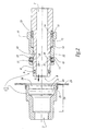
- a quick connector 1 connects a flexible pipe T at one end of a conduit C formed in a mold M of injection molding of polymer parts, this pipe T being intended to convey a coolant coolant of the mold M.
- a part female 2 of the connector 1 is fixed by screwing or in any other appropriate manner to the mold M, so that a passage 3 which the cross member from one side to the other is sealed to the conduit C.
- the connector 1 comprises, in addition to the female part 2, a male part 4 fixed to one end of the pipe T by means of a fastening collar not shown in FIG. a concern for clarity or in any other appropriate way.
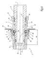
- the female part 2 consists of a hollow metal part, which is provided with an attached and clipped collar 2A. As can be seen from the figure 2 an annular and internal groove 5 of the female part 2 is formed in the inner wall which delimits the passage 3.
- the male part 4 comprises a plug 6, which is intended to be fitted in an enlarged portion 3A of the passage 3.
- This plug 6 is pierced right through an axial passage 7 for the coolant. Near its free end 8, it is provided with an annular seal 9, made of elastomer and mounted in an annular groove provided for this purpose.
- an annular seal 9 made of elastomer and mounted in an annular groove provided for this purpose.
- a spring 12 for returning this ring 10 towards the free end 8 that is to say in the direction of introduction F 1 ( figure 2 ) of the plug 6 in the female part 2, and a safety ring 13 are threaded on the plug 6.
- the constituent parts of the male part 4, in particular the plug 6 and the ring 10, are metallic.
- FIGS. 1 to 5 are schematic especially in that, for the sake of clarity, the plug 6 is shown as being in one piece while, in reality, it results from the assembly of at least two parts. These are dissociated during the installation of the ring 10 on the form 6.
- the latter is provided with a shoulder 14 forming a stop for the ring 13.
- the spring 12 is compressed between the ring 10 and the ring 13, which it pushes against the shoulder 14 while exerting a force of reminder on the ring 10 towards the end 8.
- the ring 13 is clipped on an annular boss 15 that defines the plug 6 and at which the latter has a peripheral groove 16.
- an internal radial projection 17 of the ring 13 penetrates into this groove 16, which contributes to the immobilization of the ring 13 relative to the plug 6.
- the groove 16 and the projection 17 form two complementary reliefs of immobilization of the ring 13 along the plug 6 by cooperation of forms.
- the projection 17 can equip the plug 6, while the hollow in which this projection penetrates may be formed in the ring 13.
- the ring 13 is mounted by deforming elastically.
- radial and through holes 18 are formed in the ring 10.
- a ball 11 is mounted in each of them, so as to be able to be displaced radially between two positions, in one of which it protrudes laterally of the ring 10, which is the case figures 1 and 2 . In their other position, the balls 11 are retracted radially in the ring 10, which is the case at the figure 5 .
- Each hole 18 has a distal retaining constriction 19, whose function is to prevent the ball 11 in the hole 18 from escaping.
- the balls 11 To be retracted, the balls 11 must be at an annular groove and external 20 of the plug 6, in order to be able to sink.
- the ring 10 is movable along the plug 6 between two positions, in one of which the balls 11 are at the level of this groove 20. In the other position of the ring 10, the balls 11 are at an outer surface 21 that includes the plug 6 and which has a diameter greater than that of the bottom of the groove 20.
- This other position towards which the spring 12 recalls the ring 10, is axially offset, in the insertion direction F 1 , the position in which the balls 11 are at the groove 20.
- the surface 21 has a diameter such that, if the balls 11 are at its level, it forces these balls 11 to protrude outside the ring 10.
- a ramp 22 connects the bottom of the groove 20 to the surface 21.
- the plug 6 is provided with an annular bead 23 which borders the surface 21 and which, being unable to be crossed by the balls 11, forms a stop for the mobile assembly consisting of the ring 10 and these balls. 11.
- the ring 10 is mounted with a game e on the plug 6 and with less play on the ring 13. As a result, it slides on the ring 13 and not on the form 6. In other words, The ring 13 forms a sliding guide for the ring 10.
- the coefficient of friction of the material of the ring 10 on the material of this ring 13 is less than the coefficient of friction of the ring 13. This is the case when, as in the example shown, the ring 13 is made of polymer, while the plug 6 and the ring 10 are made of metal. This facilitates the sliding of the ring 10 along the plug 6, which is advantageous.
- the ring 13 is positioned along the plug 6 so as to be visible only when the ring 10 is in the position illustrated in FIG. figure 1 or at figure 2 , that is to say in the position where it places the balls 11 at the surface 21.
- the ring 10 masks the ring 13, which is the case at the figure 5 .
- the ring 13 thus forms a visual cue, with which one can easily and quickly determine the position of the ring 10 and therefore that of the balls 11, even if they are hidden.
- the ring 13 is made to have a very different visual appearance from that of the sheet 6. In this sense, it has a color significantly different from that of the sheet 6.
- the fact that the ring 13 is made of polymer, that is to say a material different from that of the plug 6 which is metallic, also facilitates the visual differentiation of this ring 13 and the plug 6.
- the flange 2A and the ring 13 have the same color and are made of the same material, while belonging to different parts 2 and 4 of the same connector 1.
- the fact that they have coordinated aspects allows use them as visual cues to make sure that parts 2 and 4 go together, which is advantageous.
- the female part 2 and the male part 4 of the coupling 1 are dissociated.
- the return then exerted by the spring 12 causes the ring 10 to be in the position where it places the balls 11 at the level of the surface 21 and where these balls 11 are therefore forced to protrude out of the ring 10.
- the end 8 of the plug 6 is inserted into the female part 2.
- the balls 11 then meet the distal edge 24 of the female part 2.
- This distal edge 24 prevents the balls 11 from entering the portion 3A enlarged passage 3, until the groove 20 has reached the balls 11 due to a sliding of the plug 6 in the ring 10, against the force of the spring 12.
- the connection 1 is as illustrated in figure 3 and the balls 11 penetrate into the groove 20, which allows them to cross a constriction 25 which separates the groove 5 from the distal edge 24.
- the surface 21 forces the balls 11 to protrude laterally from the ring 10 and to enter the groove 5, so that these balls 11 lock the assembly of the female and male parts of the coupling 1.
- the seal 9 then ensures the seal connecting passages 3 and 7.
- the ring 10 masks the ring 13, which means that the balls 11 are not at the surface 21, that is to say in their locking position.
- the operator easily notices that the ring 10 masks the ring 13. Therefore, it can correct the position of the plug 6 relative to the female part 2 and prevent thus an accidental and dangerous ejection of the male part 4, in accordance with the purpose of the invention.
- the operator has not sufficiently depressed the plug 6 when mounting the male part 4 on the female part 2, so that the balls 11 have not reached the groove 5. While the friction of the seal 9 on the female part 2 may give it the impression that the plug 6 is properly locked, the operator easily perceives that this is not the case since the ring 10 masks the ring 13. Therefore, it can perform a corrective action.
- the plug 6 is pushed axially towards the inside of the female part 2, until it is as illustrated in FIG. figure 5 .
- the ring 10 is stopped by an internal stop 26 defined by the female part 2.
- T-pipes including at least one supply pipe and a coolant discharge pipe, must be connected to the mold M by means of several connectors 1.
- connectors 1 which are distinguished from each other by the colors of their respective flanges 2A and their respective rings 13.
- a connector 1 whose flange 2A and the ring 13 are blue can be used to connect the supply pipe
- a connection 1 whose flange 2A and the ring 13 are red can be used to connect the drain pipe. This tends to reduce the risk of a connection error and makes sure the use of the mold M, in accordance with the purpose of the invention.
- the seal 9 can equip not the plug 6 but the female part 2.
Landscapes
- Engineering & Computer Science (AREA)
- Mechanical Engineering (AREA)
- General Engineering & Computer Science (AREA)
- Quick-Acting Or Multi-Walled Pipe Joints (AREA)
- Handcart (AREA)
- Arrangement And Mounting Of Devices That Control Transmission Of Motive Force (AREA)
- Vehicle Body Suspensions (AREA)
Priority Applications (1)
| Application Number | Priority Date | Filing Date | Title |
|---|---|---|---|
| PL05356185T PL1647757T3 (pl) | 2004-10-14 | 2005-10-13 | Część obejmowana szybkozłącza, szybkozłącze i zestaw dwóch takich szybkozłączy |
Applications Claiming Priority (1)
| Application Number | Priority Date | Filing Date | Title |
|---|---|---|---|
| FR0410868A FR2876775B1 (fr) | 2004-10-14 | 2004-10-14 | Partie male d'un raccord rapide, ce raccord rapide et jeu de deux tels raccords rapides |
Publications (2)
| Publication Number | Publication Date |
|---|---|
| EP1647757A1 EP1647757A1 (fr) | 2006-04-19 |
| EP1647757B1 true EP1647757B1 (fr) | 2010-09-08 |
Family
ID=34953059
Family Applications (1)
| Application Number | Title | Priority Date | Filing Date |
|---|---|---|---|
| EP05356185A Expired - Lifetime EP1647757B1 (fr) | 2004-10-14 | 2005-10-13 | Partie mâle d'un raccord rapide, ce raccord rapide et jeu de deux tels raccords rapides |
Country Status (10)
| Country | Link |
|---|---|
| US (1) | US7503592B2 (pl) |
| EP (1) | EP1647757B1 (pl) |
| JP (1) | JP2006112628A (pl) |
| CN (1) | CN1760580B (pl) |
| AT (1) | ATE480733T1 (pl) |
| DE (1) | DE602005023398D1 (pl) |
| ES (1) | ES2349860T3 (pl) |
| FR (1) | FR2876775B1 (pl) |
| PL (1) | PL1647757T3 (pl) |
| PT (1) | PT1647757E (pl) |
Families Citing this family (19)
| Publication number | Priority date | Publication date | Assignee | Title |
|---|---|---|---|---|
| DE202008005929U1 (de) * | 2008-04-29 | 2009-09-03 | Voss Automotive Gmbh | Anschlussvorrichtung für Medienleitungen im Bereich einer Wandungsdurchführung sowie Wandungselement |
| JP2010011963A (ja) * | 2008-07-02 | 2010-01-21 | Olympus Medical Systems Corp | 継手及びこれを備える内視鏡装置 |
| US20100289256A1 (en) * | 2009-05-18 | 2010-11-18 | Dennis Shumard | Pipe insertion indicator and method of use |
| JP5577868B2 (ja) * | 2010-06-11 | 2014-08-27 | 住友電装株式会社 | ガス配管用コネクタ |
| US8640931B2 (en) | 2011-02-01 | 2014-02-04 | Emerald Wine Systems, LLC | Tri-function tap for beverages |
| CN102628534B (zh) * | 2012-04-10 | 2014-01-15 | 合肥美的电冰箱有限公司 | 用于水管的接头组件及具有该接头组件的水管和冰箱 |
| US9175795B2 (en) | 2012-05-29 | 2015-11-03 | Parker-Hannifin Corporation | Coupling with locking bars |
| US20140182721A1 (en) * | 2012-12-28 | 2014-07-03 | Parker-Hannifin Corporation | Pressure balanced coupler |
| WO2014108760A1 (en) * | 2013-01-14 | 2014-07-17 | Manuli Rubber Industries S.P.A. | Quick connector |
| CN103486375B (zh) * | 2013-08-30 | 2015-07-15 | 北京航天发射技术研究所 | 气路插拔组合连接器 |
| US9334995B2 (en) | 2013-11-08 | 2016-05-10 | Campbell Fittings, Inc. | Single lock and double lock couplings having a locking ring with identifying indicia and methods of use and assembly |
| DK201470309A (da) * | 2014-05-28 | 2014-06-02 | Lego As | Formværktøj til sprøjtestøbning |
| CN104533184B (zh) * | 2014-12-22 | 2016-11-09 | 苏州德仕耐五金技术有限公司 | 用于板与板之间的快速连接器 |
| GB2543574B (en) * | 2015-10-23 | 2017-12-20 | Balltec Ltd | Connector with independently movable cages |
| US10221950B1 (en) | 2017-08-17 | 2019-03-05 | Stedlin Manufacturing Incorporated | High pressure coupler |
| CN112005041B (zh) | 2018-04-30 | 2021-10-26 | 希恩公司 | 用于快速连接式联接器的锁定机构 |
| CN109707941B (zh) * | 2018-12-19 | 2024-04-09 | 杭州航天电子技术有限公司 | 一种导轨式分离的流体连接器 |
| JP7382619B2 (ja) * | 2019-04-22 | 2023-11-17 | パインパシフィック コーポレーション リミテッド | 鋳造用鋳型製造装置 |
| FR3098566B1 (fr) * | 2019-07-12 | 2021-06-11 | Hutchinson | Dispositif de raccordement fluidique |
Family Cites Families (13)
| Publication number | Priority date | Publication date | Assignee | Title |
|---|---|---|---|---|
| US3112767A (en) * | 1960-10-21 | 1963-12-03 | Crawford Fitting Co | Quick-connect coupling |
| FR1556209A (pl) | 1967-06-01 | 1969-02-07 | ||
| DE2653975C3 (de) * | 1976-11-27 | 1979-07-19 | Carl Kurt Walther Gmbh & Co Kg, 5600 Wuppertal | Schnellkupplung mit einer entgegen Federbelastung in axialer Richtung verlagerbaren Verriegelungshülse |
| SE448912B (sv) * | 1981-02-16 | 1987-03-23 | Ekman K R | Skyddsanordning for en snabbkopplingsdel |
| US4637914A (en) * | 1984-01-30 | 1987-01-20 | Westinghouse Electric Corp. | Quick release guide sleeve assembly |
| US5139444A (en) * | 1991-09-17 | 1992-08-18 | Raytheon Company | Insulating jack plug and method for making |
| US6073973A (en) * | 1996-10-31 | 2000-06-13 | Stanley Aviation Corporation | Lightweight positive lock coupling |
| CN2267373Y (zh) * | 1996-12-23 | 1997-11-12 | 白桂森 | 直插式快速管接头 |
| CA2205760C (en) * | 1997-03-18 | 2000-07-18 | Rory Mclaren | Safety bleed assembly for a hydraulic system |
| US6279242B1 (en) * | 1999-09-13 | 2001-08-28 | Swagelok Company | Intrinsic gauging for tube fittings |
| JP2003113981A (ja) * | 2001-10-02 | 2003-04-18 | Smc Corp | カプラー |
| GB0213705D0 (en) * | 2002-06-14 | 2002-07-24 | Powerlogic Internat Bv | Electrical connectors |
| AUPS315002A0 (en) * | 2002-06-25 | 2002-07-18 | Resmed Limited | Method & apparatus for control of appliance coupler retention and withdrawal forces |
-
2004
- 2004-10-14 FR FR0410868A patent/FR2876775B1/fr not_active Expired - Fee Related
-
2005
- 2005-10-13 US US11/248,259 patent/US7503592B2/en not_active Expired - Lifetime
- 2005-10-13 EP EP05356185A patent/EP1647757B1/fr not_active Expired - Lifetime
- 2005-10-13 CN CN2005101083676A patent/CN1760580B/zh not_active Expired - Fee Related
- 2005-10-13 AT AT05356185T patent/ATE480733T1/de not_active IP Right Cessation
- 2005-10-13 DE DE602005023398T patent/DE602005023398D1/de not_active Expired - Lifetime
- 2005-10-13 PL PL05356185T patent/PL1647757T3/pl unknown
- 2005-10-13 ES ES05356185T patent/ES2349860T3/es not_active Expired - Lifetime
- 2005-10-13 JP JP2005298804A patent/JP2006112628A/ja not_active Withdrawn
- 2005-10-13 PT PT05356185T patent/PT1647757E/pt unknown
Also Published As
| Publication number | Publication date |
|---|---|
| DE602005023398D1 (de) | 2010-10-21 |
| CN1760580A (zh) | 2006-04-19 |
| EP1647757A1 (fr) | 2006-04-19 |
| CN1760580B (zh) | 2011-07-13 |
| FR2876775B1 (fr) | 2006-12-08 |
| FR2876775A1 (fr) | 2006-04-21 |
| US20060082148A1 (en) | 2006-04-20 |
| US7503592B2 (en) | 2009-03-17 |
| JP2006112628A (ja) | 2006-04-27 |
| ES2349860T3 (es) | 2011-01-12 |
| PT1647757E (pt) | 2010-11-04 |
| ATE480733T1 (de) | 2010-09-15 |
| PL1647757T3 (pl) | 2011-02-28 |
Similar Documents
| Publication | Publication Date | Title |
|---|---|---|
| EP1647757B1 (fr) | Partie mâle d'un raccord rapide, ce raccord rapide et jeu de deux tels raccords rapides | |
| EP2908042B1 (fr) | Raccord à baïonnette adapté pour la jonction amovible de canalisations | |
| EP1853842B1 (fr) | Raccord rapide pour la jonction de deux canalisations d'acheminement d'un gaz sous pression | |
| JP5317761B2 (ja) | 管継手用のソケット及び管継手 | |
| EP2141402B1 (fr) | Elément de raccord à griffes et raccord incorporant un tel élément | |
| WO2006084969A1 (fr) | Dispositif de raccordement instantane avec moyen de verrouillage et/ou de deconnexion | |
| FR2718822A1 (fr) | Accouplement emboîtable à désaccouplement simplifié, pour relier deux conduits de circulation d'un fluide. | |
| FR2927143A1 (fr) | Element femelle de raccord et raccord rapide incorporant un tel element | |
| FR2873185A1 (fr) | Cartouche d'implantation pour un raccord de tuyau destine a prendre place dans un logement | |
| FR2673699A1 (fr) | Accouplement emboitable pour relier un flexible a un tube muni d'une nervure peripherique de retenue. | |
| FR2840050A1 (fr) | Raccord rapide | |
| FR2930904A1 (fr) | Assemblage de raccord rapide et outil de degagement | |
| EP1980782A1 (fr) | Elément femelle de raccord et raccord rapide comprenant un tel élément femelle | |
| FR2883607A1 (fr) | Dispositif de raccordement de deux elements | |
| EP2817548A1 (fr) | Dispositif de raccordement étanche sans zone de rétention | |
| WO2021038162A1 (fr) | Dispositif de raccordement, notamment pour la réalisation de circuit de circulation de fluide | |
| EP3501737B1 (fr) | Outil et procede d'installation d'un joint d etancheite en permettant une pre-compression pour assembler deux pieces tubulaires | |
| EP4124788A1 (fr) | Élément mâle de raccord fluidique et raccord fluidique comprenant un tel élément mâle | |
| WO2009044024A2 (fr) | Ensemble pour collier à griffes, collier et liaison tubulaire correspondants | |
| FR2783590A1 (fr) | Dispositif de raccordement instantane pour tuyau | |
| FR3072755B1 (fr) | Dispositif de raccord tubulaire avec bague securisee comprenant un indicateur d’etat de montage | |
| EP2101097B1 (fr) | Dispositif de raccordement pour transfert de fluide, circuit l'incorporant et son procédé de montage/démontage | |
| EP0364380B1 (fr) | Raccord, notamment pour circuit hydraulique haute pression | |
| FR2930620A1 (fr) | Raccord instantane pour au moins un tube | |
| WO2022064143A1 (fr) | Raccord instantané pour tubes |
Legal Events
| Date | Code | Title | Description |
|---|---|---|---|
| PUAI | Public reference made under article 153(3) epc to a published international application that has entered the european phase |
Free format text: ORIGINAL CODE: 0009012 |
|
| AK | Designated contracting states |
Kind code of ref document: A1 Designated state(s): AT BE BG CH CY CZ DE DK EE ES FI FR GB GR HU IE IS IT LI LT LU LV MC NL PL PT RO SE SI SK TR |
|
| AX | Request for extension of the european patent |
Extension state: AL BA HR MK YU |
|
| 17P | Request for examination filed |
Effective date: 20060729 |
|
| 17Q | First examination report despatched |
Effective date: 20060913 |
|
| AKX | Designation fees paid |
Designated state(s): AT BE BG CH CY CZ DE DK EE ES FI FR GB GR HU IE IS IT LI LT LU LV MC NL PL PT RO SE SI SK TR |
|
| GRAP | Despatch of communication of intention to grant a patent |
Free format text: ORIGINAL CODE: EPIDOSNIGR1 |
|
| GRAS | Grant fee paid |
Free format text: ORIGINAL CODE: EPIDOSNIGR3 |
|
| GRAA | (expected) grant |
Free format text: ORIGINAL CODE: 0009210 |
|
| AK | Designated contracting states |
Kind code of ref document: B1 Designated state(s): AT BE BG CH CY CZ DE DK EE ES FI FR GB GR HU IE IS IT LI LT LU LV MC NL PL PT RO SE SI SK TR |
|
| REG | Reference to a national code |
Ref country code: GB Ref legal event code: FG4D Free format text: NOT ENGLISH |
|
| REG | Reference to a national code |
Ref country code: CH Ref legal event code: EP |
|
| REG | Reference to a national code |
Ref country code: IE Ref legal event code: FG4D Free format text: LANGUAGE OF EP DOCUMENT: FRENCH |
|
| REF | Corresponds to: |
Ref document number: 602005023398 Country of ref document: DE Date of ref document: 20101021 Kind code of ref document: P |
|
| REG | Reference to a national code |
Ref country code: PT Ref legal event code: SC4A Free format text: AVAILABILITY OF NATIONAL TRANSLATION Effective date: 20101027 |
|
| REG | Reference to a national code |
Ref country code: NL Ref legal event code: VDEP Effective date: 20100908 |
|
| REG | Reference to a national code |
Ref country code: ES Ref legal event code: FG2A Effective date: 20101229 |
|
| PG25 | Lapsed in a contracting state [announced via postgrant information from national office to epo] |
Ref country code: AT Free format text: LAPSE BECAUSE OF FAILURE TO SUBMIT A TRANSLATION OF THE DESCRIPTION OR TO PAY THE FEE WITHIN THE PRESCRIBED TIME-LIMIT Effective date: 20100908 Ref country code: LT Free format text: LAPSE BECAUSE OF FAILURE TO SUBMIT A TRANSLATION OF THE DESCRIPTION OR TO PAY THE FEE WITHIN THE PRESCRIBED TIME-LIMIT Effective date: 20100908 Ref country code: FI Free format text: LAPSE BECAUSE OF FAILURE TO SUBMIT A TRANSLATION OF THE DESCRIPTION OR TO PAY THE FEE WITHIN THE PRESCRIBED TIME-LIMIT Effective date: 20100908 |
|
| LTIE | Lt: invalidation of european patent or patent extension |
Effective date: 20100908 |
|
| PG25 | Lapsed in a contracting state [announced via postgrant information from national office to epo] |
Ref country code: SI Free format text: LAPSE BECAUSE OF FAILURE TO SUBMIT A TRANSLATION OF THE DESCRIPTION OR TO PAY THE FEE WITHIN THE PRESCRIBED TIME-LIMIT Effective date: 20100908 Ref country code: CY Free format text: LAPSE BECAUSE OF FAILURE TO SUBMIT A TRANSLATION OF THE DESCRIPTION OR TO PAY THE FEE WITHIN THE PRESCRIBED TIME-LIMIT Effective date: 20100908 |
|
| REG | Reference to a national code |
Ref country code: PL Ref legal event code: T3 |
|
| REG | Reference to a national code |
Ref country code: IE Ref legal event code: FD4D |
|
| PG25 | Lapsed in a contracting state [announced via postgrant information from national office to epo] |
Ref country code: NL Free format text: LAPSE BECAUSE OF FAILURE TO SUBMIT A TRANSLATION OF THE DESCRIPTION OR TO PAY THE FEE WITHIN THE PRESCRIBED TIME-LIMIT Effective date: 20100908 Ref country code: SE Free format text: LAPSE BECAUSE OF FAILURE TO SUBMIT A TRANSLATION OF THE DESCRIPTION OR TO PAY THE FEE WITHIN THE PRESCRIBED TIME-LIMIT Effective date: 20100908 Ref country code: GR Free format text: LAPSE BECAUSE OF FAILURE TO SUBMIT A TRANSLATION OF THE DESCRIPTION OR TO PAY THE FEE WITHIN THE PRESCRIBED TIME-LIMIT Effective date: 20101209 Ref country code: LV Free format text: LAPSE BECAUSE OF FAILURE TO SUBMIT A TRANSLATION OF THE DESCRIPTION OR TO PAY THE FEE WITHIN THE PRESCRIBED TIME-LIMIT Effective date: 20100908 |
|
| PG25 | Lapsed in a contracting state [announced via postgrant information from national office to epo] |
Ref country code: IE Free format text: LAPSE BECAUSE OF FAILURE TO SUBMIT A TRANSLATION OF THE DESCRIPTION OR TO PAY THE FEE WITHIN THE PRESCRIBED TIME-LIMIT Effective date: 20100908 |
|
| PG25 | Lapsed in a contracting state [announced via postgrant information from national office to epo] |
Ref country code: CZ Free format text: LAPSE BECAUSE OF FAILURE TO SUBMIT A TRANSLATION OF THE DESCRIPTION OR TO PAY THE FEE WITHIN THE PRESCRIBED TIME-LIMIT Effective date: 20100908 Ref country code: MC Free format text: LAPSE BECAUSE OF NON-PAYMENT OF DUE FEES Effective date: 20101031 Ref country code: EE Free format text: LAPSE BECAUSE OF FAILURE TO SUBMIT A TRANSLATION OF THE DESCRIPTION OR TO PAY THE FEE WITHIN THE PRESCRIBED TIME-LIMIT Effective date: 20100908 Ref country code: SK Free format text: LAPSE BECAUSE OF FAILURE TO SUBMIT A TRANSLATION OF THE DESCRIPTION OR TO PAY THE FEE WITHIN THE PRESCRIBED TIME-LIMIT Effective date: 20100908 Ref country code: IS Free format text: LAPSE BECAUSE OF FAILURE TO SUBMIT A TRANSLATION OF THE DESCRIPTION OR TO PAY THE FEE WITHIN THE PRESCRIBED TIME-LIMIT Effective date: 20110108 Ref country code: RO Free format text: LAPSE BECAUSE OF FAILURE TO SUBMIT A TRANSLATION OF THE DESCRIPTION OR TO PAY THE FEE WITHIN THE PRESCRIBED TIME-LIMIT Effective date: 20100908 |
|
| REG | Reference to a national code |
Ref country code: CH Ref legal event code: PL |
|
| PLBE | No opposition filed within time limit |
Free format text: ORIGINAL CODE: 0009261 |
|
| STAA | Information on the status of an ep patent application or granted ep patent |
Free format text: STATUS: NO OPPOSITION FILED WITHIN TIME LIMIT |
|
| PG25 | Lapsed in a contracting state [announced via postgrant information from national office to epo] |
Ref country code: LI Free format text: LAPSE BECAUSE OF NON-PAYMENT OF DUE FEES Effective date: 20101031 Ref country code: CH Free format text: LAPSE BECAUSE OF NON-PAYMENT OF DUE FEES Effective date: 20101031 |
|
| 26N | No opposition filed |
Effective date: 20110609 |
|
| PG25 | Lapsed in a contracting state [announced via postgrant information from national office to epo] |
Ref country code: DK Free format text: LAPSE BECAUSE OF FAILURE TO SUBMIT A TRANSLATION OF THE DESCRIPTION OR TO PAY THE FEE WITHIN THE PRESCRIBED TIME-LIMIT Effective date: 20100908 |
|
| REG | Reference to a national code |
Ref country code: DE Ref legal event code: R097 Ref document number: 602005023398 Country of ref document: DE Effective date: 20110609 |
|
| PG25 | Lapsed in a contracting state [announced via postgrant information from national office to epo] |
Ref country code: LU Free format text: LAPSE BECAUSE OF NON-PAYMENT OF DUE FEES Effective date: 20101013 Ref country code: BG Free format text: LAPSE BECAUSE OF FAILURE TO SUBMIT A TRANSLATION OF THE DESCRIPTION OR TO PAY THE FEE WITHIN THE PRESCRIBED TIME-LIMIT Effective date: 20100908 Ref country code: HU Free format text: LAPSE BECAUSE OF FAILURE TO SUBMIT A TRANSLATION OF THE DESCRIPTION OR TO PAY THE FEE WITHIN THE PRESCRIBED TIME-LIMIT Effective date: 20110309 |
|
| PG25 | Lapsed in a contracting state [announced via postgrant information from national office to epo] |
Ref country code: BG Free format text: LAPSE BECAUSE OF FAILURE TO SUBMIT A TRANSLATION OF THE DESCRIPTION OR TO PAY THE FEE WITHIN THE PRESCRIBED TIME-LIMIT Effective date: 20101208 |
|
| REG | Reference to a national code |
Ref country code: FR Ref legal event code: PLFP Year of fee payment: 11 |
|
| REG | Reference to a national code |
Ref country code: FR Ref legal event code: PLFP Year of fee payment: 12 |
|
| REG | Reference to a national code |
Ref country code: FR Ref legal event code: PLFP Year of fee payment: 13 |
|
| REG | Reference to a national code |
Ref country code: FR Ref legal event code: PLFP Year of fee payment: 14 |
|
| P01 | Opt-out of the competence of the unified patent court (upc) registered |
Effective date: 20230509 |
|
| PGFP | Annual fee paid to national office [announced via postgrant information from national office to epo] |
Ref country code: TR Payment date: 20230928 Year of fee payment: 19 |
|
| PGFP | Annual fee paid to national office [announced via postgrant information from national office to epo] |
Ref country code: PT Payment date: 20230926 Year of fee payment: 19 Ref country code: PL Payment date: 20230919 Year of fee payment: 19 |
|
| PGFP | Annual fee paid to national office [announced via postgrant information from national office to epo] |
Ref country code: GB Payment date: 20231027 Year of fee payment: 19 |
|
| PGFP | Annual fee paid to national office [announced via postgrant information from national office to epo] |
Ref country code: ES Payment date: 20231102 Year of fee payment: 19 |
|
| PGFP | Annual fee paid to national office [announced via postgrant information from national office to epo] |
Ref country code: IT Payment date: 20231023 Year of fee payment: 19 Ref country code: FR Payment date: 20231025 Year of fee payment: 19 Ref country code: DE Payment date: 20231027 Year of fee payment: 19 |
|
| PGFP | Annual fee paid to national office [announced via postgrant information from national office to epo] |
Ref country code: BE Payment date: 20231027 Year of fee payment: 19 |
|
| REG | Reference to a national code |
Ref country code: DE Ref legal event code: R119 Ref document number: 602005023398 Country of ref document: DE |
|
| GBPC | Gb: european patent ceased through non-payment of renewal fee |
Effective date: 20241013 |
|
| PG25 | Lapsed in a contracting state [announced via postgrant information from national office to epo] |
Ref country code: DE Free format text: LAPSE BECAUSE OF NON-PAYMENT OF DUE FEES Effective date: 20250501 |
|
| PG25 | Lapsed in a contracting state [announced via postgrant information from national office to epo] |
Ref country code: GB Free format text: LAPSE BECAUSE OF NON-PAYMENT OF DUE FEES Effective date: 20241013 |
|
| PG25 | Lapsed in a contracting state [announced via postgrant information from national office to epo] |
Ref country code: BE Free format text: LAPSE BECAUSE OF NON-PAYMENT OF DUE FEES Effective date: 20241031 |
|
| PG25 | Lapsed in a contracting state [announced via postgrant information from national office to epo] |
Ref country code: PT Free format text: LAPSE BECAUSE OF NON-PAYMENT OF DUE FEES Effective date: 20250414 |
|
| PG25 | Lapsed in a contracting state [announced via postgrant information from national office to epo] |
Ref country code: FR Free format text: LAPSE BECAUSE OF NON-PAYMENT OF DUE FEES Effective date: 20241031 |
|
| REG | Reference to a national code |
Ref country code: BE Ref legal event code: MM Effective date: 20241031 |
|
| PG25 | Lapsed in a contracting state [announced via postgrant information from national office to epo] |
Ref country code: IT Free format text: LAPSE BECAUSE OF NON-PAYMENT OF DUE FEES Effective date: 20241013 |
|
| REG | Reference to a national code |
Ref country code: ES Ref legal event code: FD2A Effective date: 20251128 |
|
| PG25 | Lapsed in a contracting state [announced via postgrant information from national office to epo] |
Ref country code: PT Free format text: LAPSE BECAUSE OF EXPIRATION OF PROTECTION Effective date: 20251022 |
|
| PG25 | Lapsed in a contracting state [announced via postgrant information from national office to epo] |
Ref country code: PT Free format text: LAPSE BECAUSE OF FAILURE TO SUBMIT A TRANSLATION OF THE DESCRIPTION OR TO PAY THE FEE WITHIN THE PRESCRIBED TIME-LIMIT Effective date: 20241014 |
|
| PG25 | Lapsed in a contracting state [announced via postgrant information from national office to epo] |
Ref country code: ES Free format text: LAPSE BECAUSE OF NON-PAYMENT OF DUE FEES Effective date: 20241014 |