EP1646906B2 - Einbauscharnier um brillenbügel elastisch zu machen - Google Patents
Einbauscharnier um brillenbügel elastisch zu machen Download PDFInfo
- Publication number
- EP1646906B2 EP1646906B2 EP04743997A EP04743997A EP1646906B2 EP 1646906 B2 EP1646906 B2 EP 1646906B2 EP 04743997 A EP04743997 A EP 04743997A EP 04743997 A EP04743997 A EP 04743997A EP 1646906 B2 EP1646906 B2 EP 1646906B2
- Authority
- EP
- European Patent Office
- Prior art keywords
- tie
- temple
- hinge
- seating
- hole
- Prior art date
- Legal status (The legal status is an assumption and is not a legal conclusion. Google has not performed a legal analysis and makes no representation as to the accuracy of the status listed.)
- Expired - Lifetime
Links
- 239000000463 material Substances 0.000 claims abstract description 6
- 239000007787 solid Substances 0.000 claims abstract description 6
- 230000037431 insertion Effects 0.000 claims 1
- 238000003780 insertion Methods 0.000 claims 1
- 230000013011 mating Effects 0.000 claims 1
- 230000000875 corresponding effect Effects 0.000 description 9
- 230000006835 compression Effects 0.000 description 4
- 238000007906 compression Methods 0.000 description 4
- 238000003801 milling Methods 0.000 description 4
- 238000000034 method Methods 0.000 description 3
- 230000005923 long-lasting effect Effects 0.000 description 2
- 229910001069 Ti alloy Inorganic materials 0.000 description 1
- 238000007792 addition Methods 0.000 description 1
- 229910045601 alloy Inorganic materials 0.000 description 1
- 239000000956 alloy Substances 0.000 description 1
- 230000004075 alteration Effects 0.000 description 1
- 229910052782 aluminium Inorganic materials 0.000 description 1
- XAGFODPZIPBFFR-UHFFFAOYSA-N aluminium Chemical compound [Al] XAGFODPZIPBFFR-UHFFFAOYSA-N 0.000 description 1
- 229920002301 cellulose acetate Polymers 0.000 description 1
- 230000003749 cleanliness Effects 0.000 description 1
- 230000002596 correlated effect Effects 0.000 description 1
- 230000008878 coupling Effects 0.000 description 1
- 238000010168 coupling process Methods 0.000 description 1
- 238000005859 coupling reaction Methods 0.000 description 1
- 238000005034 decoration Methods 0.000 description 1
- 230000001419 dependent effect Effects 0.000 description 1
- 230000000694 effects Effects 0.000 description 1
- 230000008030 elimination Effects 0.000 description 1
- 238000003379 elimination reaction Methods 0.000 description 1
- 230000001788 irregular Effects 0.000 description 1
- 229910052751 metal Inorganic materials 0.000 description 1
- 239000002184 metal Substances 0.000 description 1
- 230000004048 modification Effects 0.000 description 1
- 238000012986 modification Methods 0.000 description 1
- 230000010355 oscillation Effects 0.000 description 1
- 239000007779 soft material Substances 0.000 description 1
Images


Classifications
-
- G—PHYSICS
- G02—OPTICS
- G02C—SPECTACLES; SUNGLASSES OR GOGGLES INSOFAR AS THEY HAVE THE SAME FEATURES AS SPECTACLES; CONTACT LENSES
- G02C5/00—Constructions of non-optical parts
- G02C5/14—Side-members
- G02C5/16—Side-members resilient or with resilient parts
-
- G—PHYSICS
- G02—OPTICS
- G02C—SPECTACLES; SUNGLASSES OR GOGGLES INSOFAR AS THEY HAVE THE SAME FEATURES AS SPECTACLES; CONTACT LENSES
- G02C5/00—Constructions of non-optical parts
- G02C5/22—Hinges
- G02C5/2218—Resilient hinges
- G02C5/2236—Resilient hinges comprising a sliding hinge member and a coil spring
-
- G—PHYSICS
- G02—OPTICS
- G02C—SPECTACLES; SUNGLASSES OR GOGGLES INSOFAR AS THEY HAVE THE SAME FEATURES AS SPECTACLES; CONTACT LENSES
- G02C5/00—Constructions of non-optical parts
- G02C5/14—Side-members
-
- G—PHYSICS
- G02—OPTICS
- G02C—SPECTACLES; SUNGLASSES OR GOGGLES INSOFAR AS THEY HAVE THE SAME FEATURES AS SPECTACLES; CONTACT LENSES
- G02C2200/00—Generic mechanical aspects applicable to one or more of the groups G02C1/00 - G02C5/00 and G02C9/00 - G02C13/00 and their subgroups
- G02C2200/30—Piston
Definitions
- the present invention concerns a new conformation of the elements of a hinge in order to make adjustable, in advance, the elastic joint of two temples to two relative lateral zones, or endpieces, of a frame of a pair of spectacles, so as to ensure the best conditions for wearing the latter.
- the hinge according to the invention is completely integrated, substantially recessed, partly inside the frame and partly inside the relative temple.
- the hinge comprises at least a hinging seating made by removing material in the relative endpiece, inside which a hook element is pivoted, connected to one end of a tie-rod which in turn is mounted sliding on one end of the temple.
- the tie-rod cooperates axially with an elastic means, the compression of which is possibly adjustable by means of a threaded element arranged on the opposite side with respect to the hook element, in order to keep the temple normally in contact with the endpiece under every condition of use, and in order to exert the desired traction on the temple so as to condition the elastic return thereof to its open or closed positions.
- the elastification of the hinges for joining the temples to the frame of spectacles is intended to facilitate, with an elastic trip movement, the opening and closing step of the temples, when the spectacles are put on or taken off, or to ensure a better adherence of the temples on the temples of the person wearing the spectacles.
- the male hinging element comprises a tie-rod able to slide with respect to the temple having one end pivoted to the female element, a bushing attached inside the temple and with respect to which the tie-rod slides, and an elastic means which exerts an adjustable pressure against the bushing.
- elasticized hinges provide to replace the tie-rod with a box-like structure, solid with the male hinging element, which houses the elastic means, while the male hinging element is in any case hinged to the corresponding female element which protrudes from the endpiece of the frame.
- the bushing be attached to the end of the temple, so as to guarantee the compression of the elastic means, and hence the thrust that the latter makes in order to keep the temple normally against the frame.
- This attachment is normally made by applying screws or pins, or by making a boss or similar on the temple, in correspondence with the zone where the bushing is positioned.
- US-A-5.517.258 discloses a hinge for eyeglasses comprising a slider having a hook for engaging a recess in an engagement piece provided in the frame of the eyeglasses.
- US-A-5.400.090 and DE-A1-29 48 113 disclose other examples of hinges for eyeglasses.
- One purpose of the present invention is to achieve an elasticized hinge which allows to hinge the temples in an elasticized manner to the relative endpieces of the frame of a pair of spectacles, simply by bringing close the female elements and the male hinging elements, that is, without needing to exert supplementary compressions of the elastic means, in order to allow the alignment of the female elements and the male elements.
- Another purpose of the invention is to achieve a hinge that allows to determine the correct degree of loading of the elastic means, so as to ensure over time the desired degree of elasticity of the movement of each temple, without this load being subject to variations when it is joined to its frame.
- Another purpose of the invention is to ensure the bushing is stably joined to the temple without needing pins, screws, or bossing or otherwise.
- Another purpose of the present invention is to make a hinge having an extremely limited cost and whose hinging elements are invisible and do not protrude from the temple and from the frame, so that no protection has to be provided during the bossing steps, and at the same time to ensure a long-lasting cleanliness and duration of the hinge itself.
- Yet another purpose is to achieve a hinge which, together with the possibility of a normal elastic horizontal opening of the temples, also allows an adjustable orthogonal, and also partly rotational, opening of the temples, also in the event of knocks or irregular strains; also, to make possible a determinate pantoscopic adjustment of the frame.
- Applicant has devised, tested and embodied the present invention to overcome the shortcomings of the state of the art and to obtain these and other purposes and advantages.
- a recessed hinge according to the present invention is applied to elasticize a temple to a respective endpiece of a frame of a pair of spectacles.
- the hinge according to the invention comprises at least a male hinging element pivoted to at least a corresponding female element.
- the male hinging element comprises at least a tie-rod able to slide with respect to the temple, a bushing arranged inside the temple and axially associated with the tie-rod, and an elastic means loaded between the bushing and an abutment element attached to the tie-rod.
- the female element comprises a seating made in the endpiece by removing material
- said male element comprises a hook element, solid with the tie-rod, housed in said seating and able to articulate on a pin arranged inside said seating.
- the male hinging element comprises two tie-rods arranged co-planar and substantially parallel with each other and able to be pivoted with the relative hook elements inside the same seating, or two relative seatings, in the endpiece.
- the two tie-rods are connected in a single piece with a transverse element which functions as a pin.
- Figs. 9 to 15 do not show an embodiment of the invention as claimed.
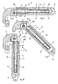
- an elasticized hinge D substantially comprises a male hinging element 100, cooperating with a corresponding female element 200, in order to hinge a temple A to a corresponding lateral zone, or endpiece 3, of a frame F of a pair of spectacles.
- the male hinging element 100 comprises ( figs. 1, 2 and 3 ) a tie-rod 12 to one end of which a hook element 1 is connected, flattened and substantially semi-cylindrical in shape, a bushing 2, an elastic means 5, in this case a helical spring, and an adjustment nut 6.
- the hook element 1 is equipped with a through hole 11, while the tie-rod 12, at the opposite end, has a threading 13.
- the tie-rod 12 is preferentially applied solid with the non-cylindrical side of the hook element 1, and in proximity with one of the two lateral straight walls.
- the bushing 2 has a slightly undulating outer surface 20, with a initial lead-in 21 shaped like a truncated cone, and a through hole 22 able to house the tie-rod 12 with a slight play.
- the elastic means 5 is arranged coaxially with the tie-rod 12 between the bushing 2 and the adjustment nut 6; the latter is screwed to the threading 13 of the tie-rod 12 in order to keep the elastic means 5 under pressure against the bushing 2.
- the female element 200 is made directly in the endpiece 3 of the frame F ( fig. 4 ) and, to be more exact, comprises at least a seating 30, made by milling and defined laterally by two opposite fins 31, of which only one is visible in the figures, having the same thickness, so as to be able two house inside them the hook element 1 of the male hinging element 100.
- the seating 30 has a milling radius R which corresponds to, or is slightly more than, the radius r of the curved part of the hook element 1, and has a milling center distant from the leading edge and the inner edge of the endpiece 3 of a distance equal to the radius R.
- Each of the two fins 31 is also equipped with a smooth through hole 32, while the other, adjacent fin 31 is equipped with a coaxial through hole with threading, in order to screw in a pin 4 ( figs. 6, 7 and 8 ) which, passing through the smooth hole 32 and through the aligned free hole 11 of the hook element 1, allows to hinge and constrain the male hinging element 100 inside the female element 200.
- Each temple A ( fig. 5 ) has one end 7 to be hinged to the endpiece 3 of the frame F, which is equipped with an axial blind hole 71 having a depth slightly greater than the length of the male hinging element 100 of the hinge D, and with a diameter that has a slight interference with respect to the average diameter of the undulating surface 20 of the bushing 2 to be housed.
- a temple A for example made of cellulose acetate or other plastic material, is intended to be hinged to the frame F of a pair of spectacles, by interposing the hinge D as described heretofore, which is already assembled.
- a first step we proceed to introduce the male hinging element 100 inside the hole 71 of the end 7 of the temple A, exerting an adequate pressure, in cold conditions, on the bushing 2, also due to the effect of the lead-in 21, until the undulating surface 20 clamps the bushing 2 through interference inside the hole 71 of the temple A.
- the introduction of the bushing 2 under cold conditions inside the hole 71 of the temple A makes the position of the bushing 2 stable on the end 7 of the temple A, and achieves a solid and long-lasting coupling, and also resistant to the opening forces, without needing screws, clamping pins, bosses or otherwise, in conformity with another of the purposes specified above.
- an analogous hinge D is applicable also in the case of temples A made of other material, for example of aluminum or its alloys and other titanium alloys; it is sufficient to shape the outer surface 20 of the bushing 2, with suitable shapes and adequate tolerances, correlated to the hole 71 in the respective ends 7 of the temple A, in which hole 71 the bushing 2 is housed in a forced manner, so that in any case a cold application of the male hinging element 100 is possible in every type of temple A.
- a first evident variation is that in one end 7 1 of a temple A 1 , having a sufficiently ample front surface, two parallel and co-planar male hinging elements 100 1 are arranged, vertically adjacent to each other and able to couple with two female elements 200 1 , the latter made by milling directly on the endpiece 3 1 , and comprising corresponding seatings 30 1 .
- the bushing 2 is replaced by a final segment 72 of the end 7 1 of the temple A 1 , which comprises two cylindrical holes 73, each one able to house in, sliding and in through manner, a corresponding tie-rod 12 1 of the male hinging element 100 1 .
- each tie-rod 12 1 can be translated axially into the corresponding hole 73 and protrudes at the front from the latter with the hook element 1 1 so that it is able to be associated with a single pin 4 1 which passes through the two seatings 30 1 made by milling in the endpiece 3 1 , according to the joining methods already described above.
- the ends of the tie-rods 12 1 have a threading 13 1 so that a nut 6 1 can be screwed in, able to compress the elastic means 5 1 , which, during the assembly step, is arranged inside the respective hole 71 1 before the tie-rods 12 1 of the male hinging elements 100 1 are inserted.
- the two holes 71 1 , housing the tie-rods 12 1 , their nuts 6 1 , and the respective elastic means 5 1 are preferentially covered by a plate 75 which can be on the outer side of the temple A 1 .
- the plate 75 can be glued or attached mechanically to the temple A 1 and can constitute an original solution for the application of a trademark or other decoration of the spectacles, thus achieving another advantageous use.
- the hinge D 2 comprises two male hinging elements 100 2 arranged substantially parallel and co-planar inside respective holes 71 2 made at the end 7 2 of the temple A 2 .
- the two hook elements 1 are replaced by a joining coil 60 wound around a single pin 4 2 and able to connect together the two ends of the tie-rods 12 2 protruding from the holes 71 2 .
- the female element 200 2 comprises, instead, a single seating 30 2 made on the endpiece 3 2 and is able to house inside it the joining coil 60 and both the protruding ends of the two tie-rods 12 2 .
- the male hinging element 100 2 shown above comprises an elastic means 5 2 compressed in a desired manner between the bushing 2 2 and the nut 6 2 in order to confer elasticity on the hinge D 2 formed, while the male hinging element 100 2 shown below is without the elastic means 5 2 and comprises only the bushing 2 2 which functions as a guide element for the respective tie-rod 12 2 .
- the two male hinging elements 100 2 respectively function as elastic actuator and guide.
- Fig. 13 shows another variant of the elasticized hinge, in this case indicated in its entirety by the letter D 3 .
- the male hinging element 100 3 provided as in the previous cases with a tie-rod 12 3 , a bushing 2 3 , an elastic means 5 3 and a nut 6 3 , and the female element 200 3 , provided with a seating 30 3 , are arranged and made inside corresponding containing boxes 50 and 51, associated respectively with the temple A 3 and the endpiece 3 3 .
- the male hinging element 100 4 of the hinge D 4 is substantially U-shaped, and comprises two tie-rods 12 4 connected to each other by a segment 14 orthogonal thereto.
- Each tie-rod 12 4 is inserted in a respective hole 71 4 made on the temple A 4 .
- both the tie-rods 12 4 are associated with a respective elastic means 5 4 compressed in a desired manner between a bushing 2 4 and a nut 6 4 .
- the female element 200 4 comprises, in this case, a hook element 40, open on one side and partly drowned inside the seating 30 4 made on the endpiece 3 4 .
- the hinging is achieved by associating the segment 14, which functions as a pin, with the hook element 40.
- the hook element 1, 1 1 can consist of a bent metal wire, connected to, or made in a piece with, the end of the respective tie-rod 12, 12 1 .
Landscapes
- Physics & Mathematics (AREA)
- Health & Medical Sciences (AREA)
- General Physics & Mathematics (AREA)
- Ophthalmology & Optometry (AREA)
- Optics & Photonics (AREA)
- Eyeglasses (AREA)
- Pivots And Pivotal Connections (AREA)
- Laminated Bodies (AREA)
- Springs (AREA)
- Hooks, Suction Cups, And Attachment By Adhesive Means (AREA)
- Peptides Or Proteins (AREA)
Claims (16)
- Einbauscharnier, um einen Bügel (A, A1, A2, A3, A4) elastisch zu machen, im Bezug zu einem jeweiligen Endstück (3, 31, 32, 33, 34) eines Rahmens (F) einer Brille, wobei dieses Scharnier beinhaltet:- mindestens ein männliches Scharnierelement (100, 1001, 1002, 1003, 1004), welches an mindestens einem korrespondierenden weiblichen Element (200, 2001, 2002, 2003, 2004) drehbar gelagert ist, mittels eines Stiftes (4, 41, 42, 14), der in das Endstück durch mindestens ein in das Endstück eingebrachtes Durchgangsloch (32, 321) eingeführt ist, und das männliche Scharnierelement (100, 1001, 1002, 1003, 1004) mindestens einen Ankerstab (12, 121, 122, 123, 124) beinhaltet, welcher dazu geeignet ist, in Bezug zum Bügel (A, A1, A2, A3, A4) zu gleiten,- eine Führungsbuchse (2, 22, 23, 24, 73), welche innerhalb des Bügels (A, A1, A2, A3, A4) angeordnet ist und koaxial auf dem Ankerstab (12, 121, 122, 123, 124) auflagert,- und ein elastisches Mittel (5, 51, 52, 53, 54), welches zwischen der Führungsbuchse (2, 22, 23, 24, 73) und einem an dem Ankerstab (12, 121, 122, 123, 124) befestigten Widerlagerelement (6, 61, 62, 63, 64) eingespannt ist,wobei das weibliche Element (200, 2001, 2002, 2003, 2004) eine Aufnahme (30, 301, 302, 303, 304) beinhaltet, welche durch Abtragen von Material innerhalb des Endstücks (3, 31, 32, 33, 34) eingebracht ist,
und wobei das männliche Scharnierelement (100, 1001, 1002, 1003, 1004) ein Hakenelement (1, 11, 14, 60) beinhaltet, welches am Ankerstab (12, 121, 122, 123, 124) festliegt und in der Aufnahme (30, 301, 302, 303, 304) aufgenommen ist und dazu geeignet ist auf dem Stift (4, 41, 42, 14) ein Gelenk zu bilden,
dadurch gekennzeichnet, dass
die Aufnahme (30) im Endstück definiert ist, durch einen Innenrand, der eine Widerlager-Ebene für den Bügel (A, A1, A2, A3, A4) im geschlossenen Zustand definiert, und durch einen Führungsrand, der eine Widerlager-Ebene für den Bügel (A, A1, A2, A3, A4) im offenen Zustand definiert,
wobei die Innen- und Führungsränder im Wesentlichen geradlinig und im Wesentlichen rechtwinklig zueinander sind und zwischen sich eine Ecke definieren, wobei der Abstand zwischen der Achse des Durchgangslochs (32, 321) und der Ecke größer als die Abstände zwischen der Achse des Durchgangslochs (32, 321) und den Innen- und Führungsrändern ist,
und dass das männliche Scharnierelement durch zwei der Ankerstäbe (121) definiert ist, welche in der gleichen Ebene liegen und im Wesentlichen parallel zueinander innerhalb des zugeordneten Bügels angeordnet und um die gleiche Drehachse drehbar gelagert sind, wobei die Aufnahme (30, 301, 302, 303, 304) mindestens zwei seitliche Flügel (31, 311) beinhaltet, welche mit jeweiligen Durchgangslöchern (32, 321) ausgestattet sind, mit denen ein zentrales Loch (11, 111) axial fluchtet, welches quer durch das Hakenelement (1, 11, 14, 60) eingebracht ist, wobei die Durchgangslöcher (32, 321) dazu geeignet sind, das Einführen des Stiftes (4, 41, 42, 14) durch die Flügel (31, 311) und das Hakenelement (1, 11, 14, 60) zu erlauben, und wobei die Aufnahme (30, 301, 302, 303, 304) mindestens ein bogenförmiges Segment beinhaltet, welches einen Kurvenradius (R) mit Mittelpunkt in den Durchgangslöchern (32, 321) hat, der gleich oder etwas größer als ein Kurvenradius (r) des Hakenelementes (1, 11) mit Mittelpunkt im zentralen Loch (11, 111) ist. - Einbauscharnier nach Anspruch 1, dadurch gekennzeichnet, dass die zwei Ankerstäbe (121) innerhalb zugehörige Aufnahmen (301) aufgenommen sind, welche voneinander getrennt sind.
- Einbauscharnier nach Anspruch 1, dadurch gekennzeichnet, dass die zwei Ankerstäbe (122, 124) innerhalb einer einzigen gemeinsamen Aufnahme (302, 304) aufgenommen sind.
- Einbauscharnier nach einem der vorhergehenden Ansprüche, dadurch gekennzeichnet, dass jedes Hakenelement (1, 11, 14, 60) mit einem Durchgangsloch (11) ausgestattet ist, in welches der Gelenkstift (4, 41, 42, 14) einführbar ist.
- Einbauscharnier nach Anspruch 2 oder 3, dadurch gekennzeichnet, dass es einen einzigen Stift (4, 42,14) beinhaltet, um die Ankerstäbe (121, 122, 124) drehbar zu lagern.
- Einbauscharnier nach Anspruch 1, dadurch gekennzeichnet, dass mindestens eines der Durchgangslöcher (32, 321) mit einem Gewinde versehen ist, um es dem Stift (4, 41, 42, 14) zu erlauben, darin eingeschraubt zu werden.
- Einbauscharnier nach Anspruch 1, dadurch gekennzeichnet, dass die Aufnahme (30, 301, 302, 303, 304) mindestens zwei Seiten beinhaltet, welche eine Tiefe in Bezug zu der Achse der Durchgangslöcher (32, 321) hat, welche größer ist, als der Kurvenradius (r) des Hakenelements (1, 11) mit Mittelpunkt im zentralen Loch (11, 111).
- Einbauscharnier nach einem der vorhergehenden Ansprüche, dadurch gekennzeichnet, dass die Führungsbuchse (2, 22, 23, 24) eine leicht wellige äußere Oberfläche (20) beinhaltet, eine Einführung (21) in Form eines Kegelstumpfes, und ein Durchgangsloch (22), welches dazu geeignet ist, den Ankerstab (12, 122, 123, 124) mit leichtem Spiel aufzunehmen.
- Einbauscharnier nach Anspruch 1, dadurch gekennzeichnet, dass die Führungsbuchse (2, 22, 23, 24) mit Kraftaufwand unter kalten Bedingungen in das passende Loch (71, 712, 713, 714), welches im zugehörigen Bügel (A, A2, A3, A4) eingebracht ist, eingeführt ist.
- Einbauscharnier nach einem der vorhergehenden Ansprüche, dadurch gekennzeichnet, dass die Führungsbuchse an einem Ende (71) des Bügels (A1) vorgesehen ist und ein Durchgangsloch (73) beinhaltet, welches koaxial eingebracht ist und einen verringerten Durchmesser im Bezug zu einem Loch (711) hat.
- Einbauscharnier nach Anspruch 10, dadurch gekennzeichnet, dass das Loch (711) auf einer Seite offen ist und dazu geeignet ist, wahlweise durch eine Platte (75) geschlossen zu werden.
- Einbauscharnier nach Anspruch 3, dadurch gekennzeichnet, dass die zwei Ankerstäbe (122) miteinander verbunden sind, innerhalb der Aufnahme (302) durch ein spulenartiges Verbindungselement (60), welches um einen Stift (42) herum angeordnet ist.
- Einbauscharnier nach Anspruch 3 oder 12, dadurch gekennzeichnet, dass nur einer der Ankerstäbe (122,124) einem entsprechenden Elastikmittel (52, 54) zugeordnet ist.
- Einbauscharnier nach Anspruch 1, dadurch gekennzeichnet, dass das männliche Scharnierelement (1003) und das weibliche Element (2003) innerhalb von korrespondierenden Aufnahmebehältern (50, 51) angeordnet und eingebracht sind, welche jeweils mit dem Bügel (A3) und mit dem Endstück (33) verbunden sind.
- Einbauscharnier nach Anspruch 3, dadurch gekennzeichnet, dass die zwei Ankerstäbe (124) miteinander verbunden sind, durch ein dazu rechtwinklig angeordnetes Querelement (14), welches als ein Stift wirkt und dass das weibliche Element (2004) ein Hakenelement (40) beinhaltet, das auf einer Seite offen und teilweise in die Aufnahme (304) eingetaucht ist, und dazu geeignet ist, mit dem Querelement (14) zusammen zu arbeiten, um die Drehlagerung des männlichen Scharnierelements (1004) und des weiblichen Elements (2004) zu veranlassen.
- Einbauscharnier nach einem der vorhergehenden Ansprüche, dadurch gekennzeichnet, dass das Hakenelement (1, 11, 14, 60) dazu geeignet ist in die Aufnahme (30, 301, 302, 303, 304) mit Spiel eingeführt zu werden, um eine vorbestimmte vertikale Bewegung der Bügel (A, A1, A2, A3, A4) und auch ein mögliches pantoskopisches Einstellen durch Mittel eines vorhergehenden Anpassens des Endstückes (3, 31, 32, 33, 34) zu erlauben.
Priority Applications (1)
| Application Number | Priority Date | Filing Date | Title |
|---|---|---|---|
| DE602004011617T DE602004011617T3 (de) | 2003-07-22 | 2004-07-21 | Einbauscharnier um brillenbügel elastisch zu machen |
Applications Claiming Priority (2)
| Application Number | Priority Date | Filing Date | Title |
|---|---|---|---|
| IT000011A ITBL20030011A1 (it) | 2003-07-22 | 2003-07-22 | Cerniera ad incasso per l'elasticizzazione delle astine degli occhiali |
| PCT/IB2004/002336 WO2005008317A1 (en) | 2003-07-22 | 2004-07-21 | Recessed hinge to make the temples of spectacles elastic |
Publications (3)
| Publication Number | Publication Date |
|---|---|
| EP1646906A1 EP1646906A1 (de) | 2006-04-19 |
| EP1646906B1 EP1646906B1 (de) | 2008-01-30 |
| EP1646906B2 true EP1646906B2 (de) | 2011-06-29 |
Family
ID=34074073
Family Applications (1)
| Application Number | Title | Priority Date | Filing Date |
|---|---|---|---|
| EP04743997A Expired - Lifetime EP1646906B2 (de) | 2003-07-22 | 2004-07-21 | Einbauscharnier um brillenbügel elastisch zu machen |
Country Status (15)
| Country | Link |
|---|---|
| US (1) | US7232216B2 (de) |
| EP (1) | EP1646906B2 (de) |
| JP (1) | JP2006528370A (de) |
| KR (1) | KR20060061800A (de) |
| CN (1) | CN1839335A (de) |
| AT (1) | ATE385323T1 (de) |
| AU (1) | AU2004257932C1 (de) |
| BR (1) | BRPI0412863A (de) |
| CA (1) | CA2533015A1 (de) |
| DE (1) | DE602004011617T3 (de) |
| ES (1) | ES2300794T5 (de) |
| IT (1) | ITBL20030011A1 (de) |
| NZ (1) | NZ544895A (de) |
| RU (1) | RU2345391C2 (de) |
| WO (1) | WO2005008317A1 (de) |
Families Citing this family (15)
| Publication number | Priority date | Publication date | Assignee | Title |
|---|---|---|---|---|
| FR2892477B1 (fr) * | 2005-10-20 | 2008-02-01 | Richard Chene | Mecanisme permettant un mouvement relatif entre deux pieces rigides, mais dote d'un moyen anti-rotation |
| USD553179S1 (en) * | 2006-05-03 | 2007-10-16 | Demo Holding S.A. | Hinge for spectacles |
| WO2008001398A1 (en) * | 2006-06-28 | 2008-01-03 | SAFILO SOCIETÀ AZIONARIA FABBRICA ITALIANA LAVORAZIONE OCCHIALI S.p.A. | Spectacles frame with resiliently openable arms |
| ITUD20060172A1 (it) * | 2006-07-10 | 2008-01-11 | Target S R L | Montatura per occhiali |
| ITUD20070059A1 (it) * | 2007-03-22 | 2008-09-23 | Visottica Ind Spa | Cerniera elastica e regolabile per occhiali |
| ITUD20070116A1 (it) * | 2007-06-26 | 2008-12-27 | Visottica Ind S P A Con Unic O | Cerniera elastica per occhiali |
| JP2018503140A (ja) * | 2014-11-24 | 2018-02-01 | ジャンフィリッポ パリアッチ | 衝撃又は摩擦からレンズを保護する閉位置を有する眼鏡フレーム |
| RU171546U1 (ru) * | 2016-10-10 | 2017-06-06 | Сергей Геннадьевич Тарасов | Дужка для очков |
| CN108490640B (zh) * | 2018-03-22 | 2019-08-02 | 浙江工贸职业技术学院 | 一种具有保护功能的眼镜框 |
| IT201800006736A1 (it) | 2018-06-28 | 2019-12-28 | Astina flessibile per occhiale. | |
| KR102462079B1 (ko) | 2020-12-30 | 2022-11-03 | 문경식 | 안경용 힌지 |
| CN113253487B (zh) * | 2021-06-15 | 2023-04-07 | 国网新疆电力有限公司营销服务中心(资金集约中心、计量中心) | 双向同步驱动盒和可调电力护目镜 |
| CN113777801B (zh) * | 2021-10-19 | 2024-11-22 | 郭京 | 一种眼镜架鼻梁防护配件、眼镜架及安装方法 |
| US12578592B2 (en) * | 2022-04-04 | 2026-03-17 | Google Llc | Adjustable force temple arms for head mounted wearable device |
| CN114893493A (zh) * | 2022-04-12 | 2022-08-12 | 深圳市赛金科技有限公司 | 一种自锁式连接机构 |
Citations (22)
| Publication number | Priority date | Publication date | Assignee | Title |
|---|---|---|---|---|
| US1589051A (en) † | 1921-07-25 | 1926-06-15 | Bay State Optical Co | Spectacle frame |
| US1649792A (en) † | 1922-08-21 | 1927-11-15 | Bausch & Lomb | Ophthalmic mounting and method |
| US1729901A (en) † | 1925-01-17 | 1929-10-01 | Simonds Optical Company | Manufacture of spectacle frames |
| CH368640A (it) † | 1958-04-30 | 1963-04-15 | Leonardo Meccanoptica | Dispositivo per regolare in un'armatura per occhiali l'inclinazione del frontale rispetto alle astine |
| US3944344A (en) † | 1975-01-17 | 1976-03-16 | Wicher Max F | Spectacle structure |
| FR2395521A1 (fr) † | 1977-06-21 | 1979-01-19 | Vinocur Michael | Monture de lunettes |
| FR2424558A1 (fr) † | 1978-04-25 | 1979-11-23 | Obe Werk Kg | Charniere a ressort pour monture de lunettes |
| IT1147198B (it) † | 1981-12-21 | 1986-11-19 | Ideal Di Montagner Luciano | Stanghetta con cerniera elastica per occhiali |
| EP0262099A2 (de) † | 1986-09-23 | 1988-03-30 | SAFILO S.p.A. | Scharnier zur elastischen Befestigung von Brillenbügeln am Gestell |
| EP0340161A1 (de) † | 1988-04-29 | 1989-11-02 | Ln Industries S.A. | Elastisches Scharnier für ein Brillengestell |
| IT1227739B (it) † | 1988-12-28 | 1991-05-06 | Leonardo Meccanoptica | Cerniera a struttura perfezionata, per l'articolazione elastica delle astine, nelle montature per occhiali |
| EP0462936A1 (de) † | 1990-06-21 | 1991-12-27 | Ln Industries S.A. | Federscharnier für Brillenfassung |
| IT1239847B (it) † | 1989-01-04 | 1993-11-15 | Jean-Yves Malfroy | Cerniera elastica per stanghetta di montatura di occhiali. |
| GB2268282A (en) † | 1992-06-23 | 1994-01-05 | Ottica Far East Ltd | Elastic hinge for spectacles |
| DE9320469U1 (de) † | 1993-03-05 | 1995-01-26 | Koch, Hubert, 41844 Wegberg | Pendeltürscharnier |
| EP0652456A1 (de) † | 1993-11-10 | 1995-05-10 | VISOTTICA S.p.A. | Federscharnier für Brille |
| WO1997032234A1 (en) † | 1996-02-29 | 1997-09-04 | Visottica S.P.A. | Elastic hinge for eyeglasses |
| US5739891A (en) † | 1997-02-18 | 1998-04-14 | Wei; Mo Sui | Temple mounting structure of an eyeglasses |
| FR2779241A1 (fr) † | 1998-06-02 | 1999-12-03 | Cebe International Sa | Paire de lunettes equipee de charnieres elastiques |
| US6000796A (en) † | 1997-01-29 | 1999-12-14 | Ln Industries Sa | Slidably resilient hinge for eyeglass frames |
| WO2003046644A1 (fr) † | 2001-11-29 | 2003-06-05 | Sipal S.A. | Charniere elastique pour monture de lunettes comprenant un axe d'articualation en forme de diabolo |
| US6585371B1 (en) † | 2002-06-14 | 2003-07-01 | Gazelle Corporation | Eyeglass frame having tension adjustable temple coupling |
Family Cites Families (20)
| Publication number | Priority date | Publication date | Assignee | Title |
|---|---|---|---|---|
| US1504212A (en) * | 1922-04-03 | 1924-08-12 | Charles O Carlson | Spectacle-hinge construction |
| DE6925299U (de) * | 1969-06-26 | 1970-10-08 | Rodenstock Optik G | Einwaermscharnierteil fuer mittelteile von brillenfassungen. |
| FR2097211A5 (de) | 1970-05-19 | 1972-03-03 | Girod Roger | |
| DE7701763U1 (de) | 1976-01-27 | 1977-04-28 | De Lotto S.P.A., San Vito Di Cadore, Belluno (Italien) | Federndes scharnier, insbesondere fuer brillen |
| FR2418477A1 (fr) * | 1978-02-24 | 1979-09-21 | Lamy & Fils Ets Auguste | Charniere a ressort pour monture de lunettes |
| DE2948113A1 (de) | 1979-11-29 | 1981-06-04 | Fa. Ferdinand Menrad, 7070 Schwäbisch Gmünd | Federscharnier fuer brillenbuegel |
| FR2517080A1 (fr) * | 1981-11-20 | 1983-05-27 | Morel Michel | Charniere pour monture de lunettes |
| DE3424263C2 (de) | 1984-06-30 | 1986-08-28 | OBE-Werk Ohnmacht & Baumgärtner GmbH & Co KG, 7536 Ispringen | Federscharnier für Brillen |
| IT1221195B (it) * | 1986-10-20 | 1990-06-21 | Faoms S N C Di Curto & Longo | Metodo di cedimento elastico della stanghetta nelle montature di occhiali |
| US5400090A (en) * | 1993-12-29 | 1995-03-21 | Chau-Chen Industry Co., Ltd. | Connecting structure for connecting a glasses temple with a glasses frame |
| US5517258A (en) * | 1994-05-16 | 1996-05-14 | Kabushiki Kaisha Nakanishi Optical | Eyeglass frame with internal spring and slider assemblies |
| DE19511167A1 (de) * | 1995-03-28 | 1996-10-10 | Obe Werk Kg | Federscharnier für Brillen |
| JP3018870U (ja) * | 1995-05-31 | 1995-11-28 | フジイオプチカル株式会社 | 眼鏡の分解式バネ丁番 |
| JPH11305171A (ja) * | 1998-04-23 | 1999-11-05 | Hideaki Tachibana | 眼鏡丁番機構 |
| FR2793323B1 (fr) * | 1999-05-06 | 2001-08-17 | Veuve Henri Chevassus Soc | Composant d'articulation elastique pour monture optique |
| JP2001013468A (ja) * | 1999-06-28 | 2001-01-19 | Murai:Kk | 眼鏡の丁番構造 |
| US6353965B1 (en) * | 1999-08-23 | 2002-03-12 | Ching Lan Co., Ltd. | Guiding sheath assembly for a hinge of an eyeglass frame |
| JP3074704U (ja) * | 2000-07-10 | 2001-01-26 | 株式会社栄光眼鏡 | メガネフレームのツル継手構造 |
| PT1322991E (pt) * | 2000-10-04 | 2007-10-11 | Safilo Societa Azion Fab Ital | ''armação de óculos com braços que podem ser abertos para fora de modo resiliente'' |
| JP3412046B2 (ja) * | 2001-10-09 | 2003-06-03 | 株式会社ホリカワ | ヒンジ片とフレーム部材との取り付け構造、その取り付け構造を備えた眼鏡、及びヒンジ片とフレーム部材との取り付け方法 |
-
2003
- 2003-07-22 IT IT000011A patent/ITBL20030011A1/it unknown
-
2004
- 2004-07-21 US US10/565,159 patent/US7232216B2/en not_active Expired - Lifetime
- 2004-07-21 ES ES04743997T patent/ES2300794T5/es not_active Expired - Lifetime
- 2004-07-21 KR KR1020067001554A patent/KR20060061800A/ko not_active Withdrawn
- 2004-07-21 CA CA002533015A patent/CA2533015A1/en not_active Abandoned
- 2004-07-21 CN CNA2004800241869A patent/CN1839335A/zh active Pending
- 2004-07-21 EP EP04743997A patent/EP1646906B2/de not_active Expired - Lifetime
- 2004-07-21 JP JP2006520925A patent/JP2006528370A/ja active Pending
- 2004-07-21 BR BRPI0412863-0A patent/BRPI0412863A/pt not_active Application Discontinuation
- 2004-07-21 NZ NZ544895A patent/NZ544895A/en not_active IP Right Cessation
- 2004-07-21 WO PCT/IB2004/002336 patent/WO2005008317A1/en not_active Ceased
- 2004-07-21 RU RU2006105409/28A patent/RU2345391C2/ru not_active IP Right Cessation
- 2004-07-21 AU AU2004257932A patent/AU2004257932C1/en not_active Ceased
- 2004-07-21 DE DE602004011617T patent/DE602004011617T3/de not_active Expired - Lifetime
- 2004-07-21 AT AT04743997T patent/ATE385323T1/de not_active IP Right Cessation
Patent Citations (22)
| Publication number | Priority date | Publication date | Assignee | Title |
|---|---|---|---|---|
| US1589051A (en) † | 1921-07-25 | 1926-06-15 | Bay State Optical Co | Spectacle frame |
| US1649792A (en) † | 1922-08-21 | 1927-11-15 | Bausch & Lomb | Ophthalmic mounting and method |
| US1729901A (en) † | 1925-01-17 | 1929-10-01 | Simonds Optical Company | Manufacture of spectacle frames |
| CH368640A (it) † | 1958-04-30 | 1963-04-15 | Leonardo Meccanoptica | Dispositivo per regolare in un'armatura per occhiali l'inclinazione del frontale rispetto alle astine |
| US3944344A (en) † | 1975-01-17 | 1976-03-16 | Wicher Max F | Spectacle structure |
| FR2395521A1 (fr) † | 1977-06-21 | 1979-01-19 | Vinocur Michael | Monture de lunettes |
| FR2424558A1 (fr) † | 1978-04-25 | 1979-11-23 | Obe Werk Kg | Charniere a ressort pour monture de lunettes |
| IT1147198B (it) † | 1981-12-21 | 1986-11-19 | Ideal Di Montagner Luciano | Stanghetta con cerniera elastica per occhiali |
| EP0262099A2 (de) † | 1986-09-23 | 1988-03-30 | SAFILO S.p.A. | Scharnier zur elastischen Befestigung von Brillenbügeln am Gestell |
| EP0340161A1 (de) † | 1988-04-29 | 1989-11-02 | Ln Industries S.A. | Elastisches Scharnier für ein Brillengestell |
| IT1227739B (it) † | 1988-12-28 | 1991-05-06 | Leonardo Meccanoptica | Cerniera a struttura perfezionata, per l'articolazione elastica delle astine, nelle montature per occhiali |
| IT1239847B (it) † | 1989-01-04 | 1993-11-15 | Jean-Yves Malfroy | Cerniera elastica per stanghetta di montatura di occhiali. |
| EP0462936A1 (de) † | 1990-06-21 | 1991-12-27 | Ln Industries S.A. | Federscharnier für Brillenfassung |
| GB2268282A (en) † | 1992-06-23 | 1994-01-05 | Ottica Far East Ltd | Elastic hinge for spectacles |
| DE9320469U1 (de) † | 1993-03-05 | 1995-01-26 | Koch, Hubert, 41844 Wegberg | Pendeltürscharnier |
| EP0652456A1 (de) † | 1993-11-10 | 1995-05-10 | VISOTTICA S.p.A. | Federscharnier für Brille |
| WO1997032234A1 (en) † | 1996-02-29 | 1997-09-04 | Visottica S.P.A. | Elastic hinge for eyeglasses |
| US6000796A (en) † | 1997-01-29 | 1999-12-14 | Ln Industries Sa | Slidably resilient hinge for eyeglass frames |
| US5739891A (en) † | 1997-02-18 | 1998-04-14 | Wei; Mo Sui | Temple mounting structure of an eyeglasses |
| FR2779241A1 (fr) † | 1998-06-02 | 1999-12-03 | Cebe International Sa | Paire de lunettes equipee de charnieres elastiques |
| WO2003046644A1 (fr) † | 2001-11-29 | 2003-06-05 | Sipal S.A. | Charniere elastique pour monture de lunettes comprenant un axe d'articualation en forme de diabolo |
| US6585371B1 (en) † | 2002-06-14 | 2003-07-01 | Gazelle Corporation | Eyeglass frame having tension adjustable temple coupling |
Also Published As
| Publication number | Publication date |
|---|---|
| CA2533015A1 (en) | 2005-01-27 |
| DE602004011617T3 (de) | 2012-04-12 |
| AU2004257932C1 (en) | 2010-06-24 |
| DE602004011617D1 (de) | 2008-03-20 |
| ITBL20030011A1 (it) | 2005-01-23 |
| DE602004011617T2 (de) | 2009-01-29 |
| ES2300794T5 (es) | 2011-11-23 |
| AU2004257932A1 (en) | 2005-01-27 |
| EP1646906B1 (de) | 2008-01-30 |
| BRPI0412863A (pt) | 2006-10-03 |
| NZ544895A (en) | 2007-12-21 |
| JP2006528370A (ja) | 2006-12-14 |
| WO2005008317A1 (en) | 2005-01-27 |
| CN1839335A (zh) | 2006-09-27 |
| ES2300794T3 (es) | 2008-06-16 |
| US20060209251A1 (en) | 2006-09-21 |
| ATE385323T1 (de) | 2008-02-15 |
| KR20060061800A (ko) | 2006-06-08 |
| EP1646906A1 (de) | 2006-04-19 |
| US7232216B2 (en) | 2007-06-19 |
| AU2004257932B2 (en) | 2010-02-18 |
| RU2006105409A (ru) | 2006-08-10 |
| RU2345391C2 (ru) | 2009-01-27 |
Similar Documents
| Publication | Publication Date | Title |
|---|---|---|
| EP1646906B2 (de) | Einbauscharnier um brillenbügel elastisch zu machen | |
| US6353965B1 (en) | Guiding sheath assembly for a hinge of an eyeglass frame | |
| KR101183333B1 (ko) | 안경테 | |
| EP2120087B1 (de) | Elastisches miniaturisiertes Scharnier für einen flexiblen Bügel | |
| KR20120004434A (ko) | 텔레스코픽 힌지를 구비한 안경용 프레임과 프레임용 힌지 | |
| US6394599B1 (en) | Spectacles with open-sided assembly members | |
| KR101114547B1 (ko) | 안경 구조체 | |
| EP1114352B1 (de) | Scharnierarm mit elastischer vorrichtung für brillenbügel | |
| KR20000065095A (ko) | 안경용귀부품에탄성을주기위한소형장치 | |
| KR101871463B1 (ko) | 망원 힌지 및 오프셋 스프링을 구비하는 안경 프레임 | |
| JP2001500991A (ja) | 眼鏡の平板なつる用弾性ヒンジ | |
| CN213182220U (zh) | 一种超轻眼镜 | |
| ITFI980169A1 (it) | Montatura per occhiali con cerniera formata in filo metallico ed occhiali comprendenti detta montatura | |
| EP1073927A1 (de) | Brillenkomponenten für befestigung an linsen | |
| JPH02264214A (ja) | 眼鏡ヒンジ | |
| ITUD20070059A1 (it) | Cerniera elastica e regolabile per occhiali | |
| US20180239166A1 (en) | Screwless hinge for a pair of eyeglasses | |
| KR101870528B1 (ko) | 조립형 안경 | |
| KR102571096B1 (ko) | 안경테와 안경다리의 연결구조 | |
| CN216286030U (zh) | 一种结构简单的眼镜腿组件 | |
| ITUD990131A1 (it) | Cerniera per occhiali | |
| CN117233979A (zh) | 一种眼镜腿 | |
| JP3022944U (ja) | 眼鏡フレーム用バネ丁番 | |
| CN101539670B (zh) | 眼镜铰链的组装元件,眼镜铰链及相关的组装方法 | |
| CN1981231A (zh) | 镜框的紧凑型弹性绞接件 |
Legal Events
| Date | Code | Title | Description |
|---|---|---|---|
| PUAI | Public reference made under article 153(3) epc to a published international application that has entered the european phase |
Free format text: ORIGINAL CODE: 0009012 |
|
| 17P | Request for examination filed |
Effective date: 20060118 |
|
| AK | Designated contracting states |
Kind code of ref document: A1 Designated state(s): AT BE BG CH CY CZ DE DK EE ES FI FR GB GR HU IE IT LI LU MC NL PL PT RO SE SI SK TR |
|
| AX | Request for extension of the european patent |
Extension state: HR |
|
| TPAC | Observations filed by third parties |
Free format text: ORIGINAL CODE: EPIDOSNTIPA |
|
| RAX | Requested extension states of the european patent have changed |
Extension state: HR Payment date: 20060118 |
|
| 17Q | First examination report despatched |
Effective date: 20070328 |
|
| GRAP | Despatch of communication of intention to grant a patent |
Free format text: ORIGINAL CODE: EPIDOSNIGR1 |
|
| GRAS | Grant fee paid |
Free format text: ORIGINAL CODE: EPIDOSNIGR3 |
|
| GRAA | (expected) grant |
Free format text: ORIGINAL CODE: 0009210 |
|
| AK | Designated contracting states |
Kind code of ref document: B1 Designated state(s): AT BE BG CH CY CZ DE DK EE ES FI FR GB GR HU IE IT LI LU MC NL PL PT RO SE SI SK TR |
|
| AX | Request for extension of the european patent |
Extension state: HR |
|
| REG | Reference to a national code |
Ref country code: GB Ref legal event code: FG4D |
|
| REG | Reference to a national code |
Ref country code: CH Ref legal event code: EP |
|
| REG | Reference to a national code |
Ref country code: IE Ref legal event code: FG4D |
|
| REF | Corresponds to: |
Ref document number: 602004011617 Country of ref document: DE Date of ref document: 20080320 Kind code of ref document: P |
|
| REG | Reference to a national code |
Ref country code: CH Ref legal event code: NV Representative=s name: R. A. EGLI & CO. PATENTANWAELTE |
|
| REG | Reference to a national code |
Ref country code: ES Ref legal event code: FG2A Ref document number: 2300794 Country of ref document: ES Kind code of ref document: T3 |
|
| PG25 | Lapsed in a contracting state [announced via postgrant information from national office to epo] |
Ref country code: FI Free format text: LAPSE BECAUSE OF FAILURE TO SUBMIT A TRANSLATION OF THE DESCRIPTION OR TO PAY THE FEE WITHIN THE PRESCRIBED TIME-LIMIT Effective date: 20080130 |
|
| NLV1 | Nl: lapsed or annulled due to failure to fulfill the requirements of art. 29p and 29m of the patents act | ||
| REG | Reference to a national code |
Ref country code: HU Ref legal event code: AG4A Ref document number: E003416 Country of ref document: HU |
|
| PG25 | Lapsed in a contracting state [announced via postgrant information from national office to epo] |
Ref country code: PT Free format text: LAPSE BECAUSE OF FAILURE TO SUBMIT A TRANSLATION OF THE DESCRIPTION OR TO PAY THE FEE WITHIN THE PRESCRIBED TIME-LIMIT Effective date: 20080630 Ref country code: SI Free format text: LAPSE BECAUSE OF FAILURE TO SUBMIT A TRANSLATION OF THE DESCRIPTION OR TO PAY THE FEE WITHIN THE PRESCRIBED TIME-LIMIT Effective date: 20080130 Ref country code: PL Free format text: LAPSE BECAUSE OF FAILURE TO SUBMIT A TRANSLATION OF THE DESCRIPTION OR TO PAY THE FEE WITHIN THE PRESCRIBED TIME-LIMIT Effective date: 20080130 |
|
| ET | Fr: translation filed | ||
| PG25 | Lapsed in a contracting state [announced via postgrant information from national office to epo] |
Ref country code: DK Free format text: LAPSE BECAUSE OF FAILURE TO SUBMIT A TRANSLATION OF THE DESCRIPTION OR TO PAY THE FEE WITHIN THE PRESCRIBED TIME-LIMIT Effective date: 20080130 Ref country code: CZ Free format text: LAPSE BECAUSE OF FAILURE TO SUBMIT A TRANSLATION OF THE DESCRIPTION OR TO PAY THE FEE WITHIN THE PRESCRIBED TIME-LIMIT Effective date: 20080130 Ref country code: SK Free format text: LAPSE BECAUSE OF FAILURE TO SUBMIT A TRANSLATION OF THE DESCRIPTION OR TO PAY THE FEE WITHIN THE PRESCRIBED TIME-LIMIT Effective date: 20080130 Ref country code: SE Free format text: LAPSE BECAUSE OF FAILURE TO SUBMIT A TRANSLATION OF THE DESCRIPTION OR TO PAY THE FEE WITHIN THE PRESCRIBED TIME-LIMIT Effective date: 20080430 Ref country code: NL Free format text: LAPSE BECAUSE OF FAILURE TO SUBMIT A TRANSLATION OF THE DESCRIPTION OR TO PAY THE FEE WITHIN THE PRESCRIBED TIME-LIMIT Effective date: 20080130 |
|
| PLBI | Opposition filed |
Free format text: ORIGINAL CODE: 0009260 |
|
| PG25 | Lapsed in a contracting state [announced via postgrant information from national office to epo] |
Ref country code: RO Free format text: LAPSE BECAUSE OF FAILURE TO SUBMIT A TRANSLATION OF THE DESCRIPTION OR TO PAY THE FEE WITHIN THE PRESCRIBED TIME-LIMIT Effective date: 20080130 |
|
| 26 | Opposition filed |
Opponent name: COMOTEC SA Effective date: 20081028 |
|
| PLAX | Notice of opposition and request to file observation + time limit sent |
Free format text: ORIGINAL CODE: EPIDOSNOBS2 |
|
| PG25 | Lapsed in a contracting state [announced via postgrant information from national office to epo] |
Ref country code: MC Free format text: LAPSE BECAUSE OF NON-PAYMENT OF DUE FEES Effective date: 20080731 |
|
| PLAF | Information modified related to communication of a notice of opposition and request to file observations + time limit |
Free format text: ORIGINAL CODE: EPIDOSCOBS2 |
|
| PG25 | Lapsed in a contracting state [announced via postgrant information from national office to epo] |
Ref country code: EE Free format text: LAPSE BECAUSE OF FAILURE TO SUBMIT A TRANSLATION OF THE DESCRIPTION OR TO PAY THE FEE WITHIN THE PRESCRIBED TIME-LIMIT Effective date: 20080130 Ref country code: BG Free format text: LAPSE BECAUSE OF FAILURE TO SUBMIT A TRANSLATION OF THE DESCRIPTION OR TO PAY THE FEE WITHIN THE PRESCRIBED TIME-LIMIT Effective date: 20080430 |
|
| PLBB | Reply of patent proprietor to notice(s) of opposition received |
Free format text: ORIGINAL CODE: EPIDOSNOBS3 |
|
| PG25 | Lapsed in a contracting state [announced via postgrant information from national office to epo] |
Ref country code: CY Free format text: LAPSE BECAUSE OF FAILURE TO SUBMIT A TRANSLATION OF THE DESCRIPTION OR TO PAY THE FEE WITHIN THE PRESCRIBED TIME-LIMIT Effective date: 20080130 |
|
| PG25 | Lapsed in a contracting state [announced via postgrant information from national office to epo] |
Ref country code: TR Free format text: LAPSE BECAUSE OF FAILURE TO SUBMIT A TRANSLATION OF THE DESCRIPTION OR TO PAY THE FEE WITHIN THE PRESCRIBED TIME-LIMIT Effective date: 20080130 |
|
| APAH | Appeal reference modified |
Free format text: ORIGINAL CODE: EPIDOSCREFNO |
|
| APBA | Date of receipt of statement of grounds of appeal deleted |
Free format text: ORIGINAL CODE: EPIDOSDNOA3O |
|
| APBM | Appeal reference recorded |
Free format text: ORIGINAL CODE: EPIDOSNREFNO |
|
| APBP | Date of receipt of notice of appeal recorded |
Free format text: ORIGINAL CODE: EPIDOSNNOA2O |
|
| APBQ | Date of receipt of statement of grounds of appeal recorded |
Free format text: ORIGINAL CODE: EPIDOSNNOA3O |
|
| PG25 | Lapsed in a contracting state [announced via postgrant information from national office to epo] |
Ref country code: GR Free format text: LAPSE BECAUSE OF FAILURE TO SUBMIT A TRANSLATION OF THE DESCRIPTION OR TO PAY THE FEE WITHIN THE PRESCRIBED TIME-LIMIT Effective date: 20080501 |
|
| PGFP | Annual fee paid to national office [announced via postgrant information from national office to epo] |
Ref country code: HU Payment date: 20100812 Year of fee payment: 7 |
|
| PLAB | Opposition data, opponent's data or that of the opponent's representative modified |
Free format text: ORIGINAL CODE: 0009299OPPO |
|
| PGFP | Annual fee paid to national office [announced via postgrant information from national office to epo] |
Ref country code: AT Payment date: 20100714 Year of fee payment: 7 |
|
| R26 | Opposition filed (corrected) |
Opponent name: COMOTEC SA Effective date: 20081028 |
|
| APBU | Appeal procedure closed |
Free format text: ORIGINAL CODE: EPIDOSNNOA9O |
|
| PGFP | Annual fee paid to national office [announced via postgrant information from national office to epo] |
Ref country code: BE Payment date: 20100715 Year of fee payment: 7 |
|
| PUAH | Patent maintained in amended form |
Free format text: ORIGINAL CODE: 0009272 |
|
| STAA | Information on the status of an ep patent application or granted ep patent |
Free format text: STATUS: PATENT MAINTAINED AS AMENDED |
|
| 27A | Patent maintained in amended form |
Effective date: 20110629 |
|
| AK | Designated contracting states |
Kind code of ref document: B2 Designated state(s): AT BE BG CH CY CZ DE DK EE ES FI FR GB GR HU IE IT LI LU MC NL PL PT RO SE SI SK TR |
|
| AX | Request for extension of the european patent |
Extension state: HR |
|
| REG | Reference to a national code |
Ref country code: CH Ref legal event code: AEN Free format text: MANTENIMENTO DEL BREVETTO IN FORMA MODIFICATA |
|
| REG | Reference to a national code |
Ref country code: DE Ref legal event code: R102 Ref document number: 602004011617 Country of ref document: DE Effective date: 20110629 |
|
| REG | Reference to a national code |
Ref country code: ES Ref legal event code: DC2A Ref document number: 2300794 Country of ref document: ES Kind code of ref document: T5 Effective date: 20111123 |
|
| PG25 | Lapsed in a contracting state [announced via postgrant information from national office to epo] |
Ref country code: AT Free format text: LAPSE BECAUSE OF FAILURE TO SUBMIT A TRANSLATION OF THE DESCRIPTION OR TO PAY THE FEE WITHIN THE PRESCRIBED TIME-LIMIT Effective date: 20080130 |
|
| PGFP | Annual fee paid to national office [announced via postgrant information from national office to epo] |
Ref country code: LU Payment date: 20140123 Year of fee payment: 10 |
|
| PG25 | Lapsed in a contracting state [announced via postgrant information from national office to epo] |
Ref country code: HU Free format text: LAPSE BECAUSE OF FAILURE TO SUBMIT A TRANSLATION OF THE DESCRIPTION OR TO PAY THE FEE WITHIN THE PRESCRIBED TIME-LIMIT Effective date: 20110629 |
|
| PGFP | Annual fee paid to national office [announced via postgrant information from national office to epo] |
Ref country code: IE Payment date: 20140128 Year of fee payment: 10 Ref country code: CH Payment date: 20140121 Year of fee payment: 10 |
|
| PG25 | Lapsed in a contracting state [announced via postgrant information from national office to epo] |
Ref country code: LU Free format text: LAPSE BECAUSE OF NON-PAYMENT OF DUE FEES Effective date: 20140721 |
|
| REG | Reference to a national code |
Ref country code: CH Ref legal event code: PL |
|
| REG | Reference to a national code |
Ref country code: IE Ref legal event code: MM4A |
|
| PG25 | Lapsed in a contracting state [announced via postgrant information from national office to epo] |
Ref country code: CH Free format text: LAPSE BECAUSE OF NON-PAYMENT OF DUE FEES Effective date: 20140731 Ref country code: LI Free format text: LAPSE BECAUSE OF NON-PAYMENT OF DUE FEES Effective date: 20140731 |
|
| REG | Reference to a national code |
Ref country code: FR Ref legal event code: PLFP Year of fee payment: 12 |
|
| PG25 | Lapsed in a contracting state [announced via postgrant information from national office to epo] |
Ref country code: BE Free format text: LAPSE BECAUSE OF NON-PAYMENT OF DUE FEES Effective date: 20110731 |
|
| PG25 | Lapsed in a contracting state [announced via postgrant information from national office to epo] |
Ref country code: IE Free format text: LAPSE BECAUSE OF NON-PAYMENT OF DUE FEES Effective date: 20140721 |
|
| REG | Reference to a national code |
Ref country code: FR Ref legal event code: PLFP Year of fee payment: 13 |
|
| REG | Reference to a national code |
Ref country code: FR Ref legal event code: PLFP Year of fee payment: 14 |
|
| REG | Reference to a national code |
Ref country code: FR Ref legal event code: PLFP Year of fee payment: 15 |
|
| PGFP | Annual fee paid to national office [announced via postgrant information from national office to epo] |
Ref country code: ES Payment date: 20210927 Year of fee payment: 18 Ref country code: GB Payment date: 20210721 Year of fee payment: 18 |
|
| PGFP | Annual fee paid to national office [announced via postgrant information from national office to epo] |
Ref country code: IT Payment date: 20220728 Year of fee payment: 19 Ref country code: DE Payment date: 20220810 Year of fee payment: 19 |
|
| PGFP | Annual fee paid to national office [announced via postgrant information from national office to epo] |
Ref country code: FR Payment date: 20220706 Year of fee payment: 19 |
|
| GBPC | Gb: european patent ceased through non-payment of renewal fee |
Effective date: 20220721 |
|
| PG25 | Lapsed in a contracting state [announced via postgrant information from national office to epo] |
Ref country code: GB Free format text: LAPSE BECAUSE OF NON-PAYMENT OF DUE FEES Effective date: 20220721 |
|
| REG | Reference to a national code |
Ref country code: ES Ref legal event code: FD2A Effective date: 20230828 |
|
| PG25 | Lapsed in a contracting state [announced via postgrant information from national office to epo] |
Ref country code: ES Free format text: LAPSE BECAUSE OF NON-PAYMENT OF DUE FEES Effective date: 20220722 |
|
| REG | Reference to a national code |
Ref country code: DE Ref legal event code: R119 Ref document number: 602004011617 Country of ref document: DE |
|
| PG25 | Lapsed in a contracting state [announced via postgrant information from national office to epo] |
Ref country code: DE Free format text: LAPSE BECAUSE OF NON-PAYMENT OF DUE FEES Effective date: 20240201 |
|
| PG25 | Lapsed in a contracting state [announced via postgrant information from national office to epo] |
Ref country code: FR Free format text: LAPSE BECAUSE OF NON-PAYMENT OF DUE FEES Effective date: 20230731 |
|
| PG25 | Lapsed in a contracting state [announced via postgrant information from national office to epo] |
Ref country code: IT Free format text: LAPSE BECAUSE OF NON-PAYMENT OF DUE FEES Effective date: 20230721 |