EP1646731B1 - Verfahren zur herstellung von erz mit einem feinanteil enthaltenden gr n-agglomeraten - Google Patents
Verfahren zur herstellung von erz mit einem feinanteil enthaltenden gr n-agglomeraten Download PDFInfo
- Publication number
- EP1646731B1 EP1646731B1 EP04737378A EP04737378A EP1646731B1 EP 1646731 B1 EP1646731 B1 EP 1646731B1 EP 04737378 A EP04737378 A EP 04737378A EP 04737378 A EP04737378 A EP 04737378A EP 1646731 B1 EP1646731 B1 EP 1646731B1
- Authority
- EP
- European Patent Office
- Prior art keywords
- agglomeration drum
- combustible
- drum
- green agglomerates
- mixer
- Prior art date
- Legal status (The legal status is an assumption and is not a legal conclusion. Google has not performed a legal analysis and makes no representation as to the accuracy of the status listed.)
- Active
Links
- 238000004519 manufacturing process Methods 0.000 title claims abstract description 8
- 238000000034 method Methods 0.000 title claims description 20
- 238000005054 agglomeration Methods 0.000 claims abstract description 34
- 230000002776 aggregation Effects 0.000 claims abstract description 34
- 239000011230 binding agent Substances 0.000 claims abstract description 17
- 239000000203 mixture Substances 0.000 claims abstract description 14
- 239000000571 coke Substances 0.000 claims abstract description 11
- OKTJSMMVPCPJKN-UHFFFAOYSA-N Carbon Chemical compound [C] OKTJSMMVPCPJKN-UHFFFAOYSA-N 0.000 claims abstract description 5
- 229910052799 carbon Inorganic materials 0.000 claims abstract description 5
- 239000011248 coating agent Substances 0.000 claims abstract 3
- 238000000576 coating method Methods 0.000 claims abstract 3
- 238000005453 pelletization Methods 0.000 claims description 12
- 230000008569 process Effects 0.000 claims description 11
- -1 coke Chemical compound 0.000 claims description 3
- 230000004907 flux Effects 0.000 claims 4
- 239000000654 additive Substances 0.000 abstract description 5
- 239000000446 fuel Substances 0.000 description 22
- XEEYBQQBJWHFJM-UHFFFAOYSA-N Iron Chemical compound [Fe] XEEYBQQBJWHFJM-UHFFFAOYSA-N 0.000 description 10
- 238000005245 sintering Methods 0.000 description 8
- 239000000463 material Substances 0.000 description 7
- 229910052742 iron Inorganic materials 0.000 description 5
- ODINCKMPIJJUCX-UHFFFAOYSA-N Calcium oxide Chemical compound [Ca]=O ODINCKMPIJJUCX-UHFFFAOYSA-N 0.000 description 4
- 230000035699 permeability Effects 0.000 description 4
- XLYOFNOQVPJJNP-UHFFFAOYSA-N water Substances O XLYOFNOQVPJJNP-UHFFFAOYSA-N 0.000 description 3
- 241000273930 Brevoortia tyrannus Species 0.000 description 2
- 230000015572 biosynthetic process Effects 0.000 description 2
- 239000000292 calcium oxide Substances 0.000 description 2
- 235000012255 calcium oxide Nutrition 0.000 description 2
- 239000007789 gas Substances 0.000 description 2
- PWHULOQIROXLJO-UHFFFAOYSA-N Manganese Chemical compound [Mn] PWHULOQIROXLJO-UHFFFAOYSA-N 0.000 description 1
- 230000006978 adaptation Effects 0.000 description 1
- 230000000996 additive effect Effects 0.000 description 1
- 230000008901 benefit Effects 0.000 description 1
- AXCZMVOFGPJBDE-UHFFFAOYSA-L calcium dihydroxide Chemical compound [OH-].[OH-].[Ca+2] AXCZMVOFGPJBDE-UHFFFAOYSA-L 0.000 description 1
- 239000000920 calcium hydroxide Substances 0.000 description 1
- 235000011116 calcium hydroxide Nutrition 0.000 description 1
- 229910001861 calcium hydroxide Inorganic materials 0.000 description 1
- 230000008859 change Effects 0.000 description 1
- 238000006243 chemical reaction Methods 0.000 description 1
- 238000005253 cladding Methods 0.000 description 1
- 238000010924 continuous production Methods 0.000 description 1
- 230000008878 coupling Effects 0.000 description 1
- 238000010168 coupling process Methods 0.000 description 1
- 238000005859 coupling reaction Methods 0.000 description 1
- 230000006378 damage Effects 0.000 description 1
- 238000010586 diagram Methods 0.000 description 1
- 238000009826 distribution Methods 0.000 description 1
- 230000002349 favourable effect Effects 0.000 description 1
- 239000012467 final product Substances 0.000 description 1
- 229910052748 manganese Inorganic materials 0.000 description 1
- 239000011572 manganese Substances 0.000 description 1
- 239000002245 particle Substances 0.000 description 1
- 239000008188 pellet Substances 0.000 description 1
- 230000000750 progressive effect Effects 0.000 description 1
- 239000002994 raw material Substances 0.000 description 1
- 239000002893 slag Substances 0.000 description 1
- 230000007704 transition Effects 0.000 description 1
- 238000005303 weighing Methods 0.000 description 1
Images


Classifications
-
- C—CHEMISTRY; METALLURGY
- C22—METALLURGY; FERROUS OR NON-FERROUS ALLOYS; TREATMENT OF ALLOYS OR NON-FERROUS METALS
- C22B—PRODUCTION AND REFINING OF METALS; PRETREATMENT OF RAW MATERIALS
- C22B1/00—Preliminary treatment of ores or scrap
- C22B1/14—Agglomerating; Briquetting; Binding; Granulating
- C22B1/24—Binding; Briquetting ; Granulating
- C22B1/242—Binding; Briquetting ; Granulating with binders
- C22B1/244—Binding; Briquetting ; Granulating with binders organic
- C22B1/245—Binding; Briquetting ; Granulating with binders organic with carbonaceous material for the production of coked agglomerates
-
- C—CHEMISTRY; METALLURGY
- C22—METALLURGY; FERROUS OR NON-FERROUS ALLOYS; TREATMENT OF ALLOYS OR NON-FERROUS METALS
- C22B—PRODUCTION AND REFINING OF METALS; PRETREATMENT OF RAW MATERIALS
- C22B1/00—Preliminary treatment of ores or scrap
- C22B1/14—Agglomerating; Briquetting; Binding; Granulating
- C22B1/24—Binding; Briquetting ; Granulating
- C22B1/2406—Binding; Briquetting ; Granulating pelletizing
Definitions
- the invention relates to a process for the production of ore with a fines, aggregates and optionally a binder-containing green agglomerates, which are provided with a fine-grained carbon-containing fuel, such as coke, and optionally a binder, formed casing, wherein the ore with the Aggregates and the optionally present binder is mixed, the mixture is pelletized and the green agglomerates thus formed are coated with the addition of the fuel in an agglomeration drum with the fuel, and a plant for carrying out the method.
- a fine-grained carbon-containing fuel such as coke
- a binder formed casing
- a method of this kind is known from EP A2 0 271 863 known.
- the ore which has a fines content, is pelletized, the aggregates and the binder are pelletised.
- the green agglomerates thus formed are then transferred to a roller burnishing drum in which they are coated with fine coke.
- pelletizing plates have only a limited capacity, i. it is for a larger and more efficient system to provide a plurality of pelletizing plates, whereas it is sufficient to provide with a single agglomerating drum for wrapping the green agglomerates formed in the pelletizing plates.
- the coupling of the plurality of pelletizing plates with a single agglomerating drum is expensive, especially since a conveyor must lead from each of the pelletizing plates to the agglomerating drum. In this promotion, it may lead to the destruction of part of the green agglomerates formed.
- the invention aims to avoid these disadvantages and difficulties and has as its object to provide a method and a system for carrying out the method, which ensure a uniform and continuous process of producing the green agglomerates.
- the process should require only a little complex system for large throughputs per unit time. It's a special one Object of the invention, a change to different modes of operation - caused by different Feinerzzusammen GmbHen or different additives, etc., - To allow in a particularly simple manner.
- This object is achieved in a method of the type described above in that the mixture is pelletized in the Agglomeriertrommel and the fuel is added at a region of the longitudinal extent of Agglomeriertrommel at which forming in the Agglomeriertrommel green agglomerates for further processing have desired size.
- a particularly simple adaptation of the method according to the invention to different modes of operation, different ores, different ore compositions, etc., is characterized in that the addition area of the fuel into the agglomerating drum is varied over the length of the agglomerating drum depending on the nature and size of the green agglomerates.
- a plant for the production of ore with a fines, aggregates and optionally a binder containing green agglomerates, which are provided with a cladding containing fine-grained carbon, such as coke, which plant a mixer for the ore, the aggregates and optionally existing binder, which is arranged downstream of a pelletizer, is characterized in that the pelletizer is designed as an agglomerating drum, which is provided at an area within its longitudinal extent with an addition device for the fuel.
- a preferred embodiment is characterized in that the addition device is variable while changing the region of the longitudinal extension at which it discharges the fuel into the agglomeration drum.
- the feed device is designed as a conveyor belt protruding into the agglomerating drum, wherein expedient the conveyor belt speed is variable or the position of the conveyor belt relative to the longitudinal extension of the agglomerating drum and thus the delivery area of the conveyor belt is variable.
- augers or trough chain conveyors projecting into the agglomerating drum, which preferably can also be brought into the longitudinal direction of the agglomerating drum.
- the mixer is expediently designed as a horizontal or vertical shaft mixer with blades arranged on the shaft or on the shafts.
- the mixer with the agglomerating drum is formed ingetral, so that as soon as the ore is mixed with the additives and the optionally present binder, a direct transition takes place in the Agglomeriertrommel, whereby no separate conveyor from the mixer to Agglomeriertrommel is required.
- the region of the longitudinal extension at which the feed device for the fuel admits it to the agglomeration drum lies between the first third and the last quarter of the longitudinal extent of the agglomerating drum, preferably between the half and two thirds of the longitudinal extent of the agglomerating drum.
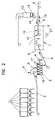
- FIGS. 1 to 4 each illustrate a variant in a schematic flow diagram representation.
- ores and aggregates, wherein also fuel, e.g. Coke can be present as an additive, taken from bunkers 1 arranged side by side and from these to a conveyor, such as a conveyor belt 2, which conveys these materials to a mixer 3, which is preferably installed express as a high-performance mixer, as will be described later.
- the materials are additionally added via a feed 4, a binder such as quicklime added.
- a binder such as quicklime added.
- water is added via a supply line 5 in a specific amount to optimize the mixing process and also the agglomeration process to be carried out subsequently in order to obtain a certain optimum moisture content.
- the mixture discharged from the mixer 3 passes via a conveying device, such as a conveyor belt 6, to an agglomeration drum 7, in which the mixture is granulated and in which the required final moisture is also adjusted via a water feed 8.
- the material passes from one feed end of the agglomerating drum 7 to the opposite discharge end from which they are conveyed further for further processing with the progressive formation of green agglomerates, which are to have a size preferably between 2 and 8 mm.
- Such further processing is preferably carried out by sintering in a belt sintering plant.
- the agglomerating drum 7 is arranged in the illustrated example in a horizontal position; However, it can also be arranged slightly inclined to increase the capacity. This also applies to the mixer 3, if this is designed as a drum mixer or high-performance mixer.
- the green agglomerates - so-called green pellets - are obtained with their fine grain size upon reaching their optimum particle size, preferably fine coke, coated.
- This adding device 9 is preferably designed as a conveyor belt whose discharge point 10 determines the region 11 to which the fuel is added to the green agglomerates.
- the task of the fuel on the conveyor belt 9 is via a bunker 12, a weighing belt 13 and a feed chute 14.
- the fuel may be provided with a fine-grained binder, e.g. with quicklime, hydrated lime or blast furnace slag with glassy structure.
- the conveyor belt 9 preferably projects into the agglomerating drum 7 via one end thereof and extends in the longitudinal direction of the agglomeration drum 7.
- the area 11 of the discharge of the fuel ie the area of the first contact of the fuel with the green agglomerates, variable, which can be accomplished by changing the conveyor belt speed, so that the Abschparabel for the fuel is changed.
- This can also be done by moving the conveyor 9 in Longitudinal direction of the agglomerating drum 7 can be achieved, as illustrated in the drawing by a double arrow 15.
- the particular advantage of the invention lies in the fact that the green agglomerates are stabilized in their shape immediately after they have been formed, specifically by the jacketing with the fuel taking place immediately thereafter.
- a pelletizer e.g. a pelletizing plate to a Brennstoffummantelungs driven, which is either also designed as a pelletizing or as Agglomeriertrommel must be promoted. Since the green agglomerates are coated with fuel immediately after they have reached the correct size within the agglomerating drum 7 and are not subjected to intermediate conveying, accurate graining of the green agglomerates is to be achieved and destroyed as they are take place at an intermediate promotion, reliably avoided.
- the invention thus makes it possible, in a particularly cost-effective manner, to process sintered raw mixtures with a high fines content into relatively coarse green agglomerates.
- the grain size of the green agglomerates can be easily adjusted according to the invention by changing the range of contact of the green agglomerates with the fuel within the length of the agglomerating drum 7.
- the coated green agglomerates thus formed have good gas permeability in a sintering machine, whereby high productivity of a sintering plant can be achieved.
- the improved permeability also makes it possible to minimize the consumption of electrical energy in a sintering machine.
- the sinter thus produced then has a high and stable quality and e.g.
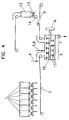
- the mixer 3 is formed as a high-performance mixer, namely, this has a horizontal, driven Shaft 16, on which radially outwardly extending blades 17 are arranged.
- the use of such a high-performance mixer lowers the humidity of the green agglomerates to a minimum value, whereby an additional increase in productivity can be achieved on a sintering machine.
- the materials in the mixture are distributed particularly homogeneously, whereby a uniform quality of the final product is ensured.
- the mixer 3 is integrally formed with the agglomerating drum 7, i.
- the mixture is introduced via the conveyor belt 2 directly into a drum, the first part of which acts as a mixer 3 and the further part of which acts as agglomerating drum 7, in which the addition of fine coke also takes place.
- the agglomerating drum 7 is also integrally formed with the mixer 3, but the agglomerating drum 7 is fixed, i.e., fixed. stationary, is arranged on the foundation and at least one shaft 16 is arranged with blades 17 inside the Agglomeriertrommel. This shaft 16 with blades 17 also passes through the mixer 3 and is drivable.
- the feed device 9 opens into the agglomerating drum 7 via an optionally placeable opening 18. According to this embodiment, mixing as well as agglomeration and sheathing take place in a single device-a mixed agglomerator-meeting the different mixing, agglomeration and sheathing requirements different design of the blades 17 in the individual areas of this Agglomeriertrommel 7 is taken into account.
- 40% of the used grains of an iron ore to be processed have a size of less than 0.125 mm.
- the humidity is 3 to 4%.
- the materials introduced into the mixer 3 are added to water in the mixer, so that the moisture content of the mixture produced is between 5 and 6%.
- the mixture thus prepared is introduced into the agglomerating drum 7, which additionally 8 t / h fine coke with about 10% moisture and a grain size less than 1 mm are supplied.
- the grain size of the green agglomerates is between 2 to 8 mm.
- the ore-green agglomerates produced in this way are outstandingly suitable for sintering as a result of the good permeability of these green agglomerates.
- the invention is not limited to the production of green agglomerates from iron ore, but is also applicable to non-iron ores such as e.g. Lead ore or manganese ore applicable.
Landscapes
- Engineering & Computer Science (AREA)
- Chemical & Material Sciences (AREA)
- Materials Engineering (AREA)
- Mechanical Engineering (AREA)
- Geology (AREA)
- General Life Sciences & Earth Sciences (AREA)
- Manufacturing & Machinery (AREA)
- Environmental & Geological Engineering (AREA)
- Life Sciences & Earth Sciences (AREA)
- Geochemistry & Mineralogy (AREA)
- Metallurgy (AREA)
- Organic Chemistry (AREA)
- Manufacture And Refinement Of Metals (AREA)
- Solid Fuels And Fuel-Associated Substances (AREA)
- Inorganic Compounds Of Heavy Metals (AREA)
- Compositions Of Oxide Ceramics (AREA)
- Medicines Containing Material From Animals Or Micro-Organisms (AREA)
- Compounds Of Alkaline-Earth Elements, Aluminum Or Rare-Earth Metals (AREA)
Description
- Die Erfindung betrifft ein Verfahren zur Herstellung von Erz mit einem Feinanteil, Zuschlagsstoffen und gegebenenfalls einen Binder enthaltenden Grün-Agglomeraten, die mit einer aus feinkörnigen Kohlenstoff enthaltenden Brennstoff, wie Koks, und gegebenenfalls einem Binder, gebildeten Ummantelung versehen sind, wobei das Erz mit den Zuschlagsstoffen und dem gegebenenfalls vorhandenen Binder durchmischt wird, die Mischung pelletiert und die so gebildeten Grün-Agglomerate unter Zugabe des Brennstoffs in einer Agglomeriertrommel mit dem Brennstoff ummantelt werden, sowie eine Anlage zur Durchführung des Verfahrens.
- Ein Verfahren dieser Art ist aus der
EP A2 0 271 863 bekannt. Gemäß diesem Dokument erfolgt das Pelletieren des Erzes, das einen Feinanteil aufweist, der Zuschlagsstoffe und des Binders mit Hilfe von Pelletiertellern. Die so gebildeten Grün-Agglomerate werden anschließend in eine Rolliertrommel überbracht, in welcher sie mit Feinkoks ummantelt werden. - Hierbei ist nachteilig, dass Pelletierteller nur eine beschränkte Kapazität aufweisen, d.h. es sind für eine größere und leistungsfähige Anlage eine Mehrzahl von Pelletiertellern vorzusehen, wogegen es genügt mit einer einzigen Agglomeriertrommel zum Ummanteln der in den Pelletiertellern gebildeten Grün-Agglomerate vorzusehen. Die Koppelung der Mehrzahl der Pelletierteller mit einer einzigen Agglomeriertrommel ist aufwendig, zumal eine Fördereinrichtung von jedem der Pelletierteller zur Agglomeriertrommel führen muss. Bei dieser Förderung kann es zur Zerstörung eines Teils der gebildeten Grün-Agglomerate kommen. Weiters ist es schwierig, dieses bekannte Verfahren kontinuierlich durchzuführen, es kommt in der Regel zu ungleichmäßigen Durchsatzmengen je Zeiteinheit an der Agglomeriertrommel, je nach dem, wie die Pelletierteller beschickt werden und wie der Pelletiervorgang auf den Pelletiertellern abläuft. Ein weiterer Nachteil ist darin zu sehen, dass die Umstellung auf andere Erze bzw. andere Korngrößenverteilungen bzw. mit unterschiedlichen Feuchtegehalten etc., aufwendig ist, zumal die Zeit zur Bildung der Grün-Agglomerate auf den Pelletiertellern in solchen Fällen variiert.
- Die Erfindung bezweckt die Vermeidung dieser Nachteile und Schwierigkeiten und stellt sich die Aufgabe, ein Verfahren bzw. eine Anlage zur Durchführung des Verfahrens zu schaffen, welche einen gleichmäßigen und kontinuierlichen Ablauf der Herstellung der Grün-Agglomerate gewährleisten. Zudem soll das Verfahren nur eine wenig aufwendige Anlage auch für große Durchsatzmengen pro Zeiteinheit erfordern. Es ist ein besonderes Anliegen der Erfindung, eine Umstellung auf unterschiedliche Betriebsweisen - hervorgerufen durch unterschiedliche Feinerzzusammensetzungen bzw. unterschiedliche Zuschlagsstoffe etc., - in besonders einfacher Weise zu ermöglichen.
- Diese Aufgabe wird erfindungsgemäß bei einem Verfahren der eingangs beschriebenen Art dadurch gelöst, dass die Mischung in der Agglomeriertrommel pelletiert wird und der Brennstoff an einem Bereich der Längserstreckung der Agglomeriertrommel zugegeben wird, an der die sich in der Agglomeriertrommel bildenden Grün-Agglomerate die für eine Weiterverarbeitung gewünschte Größe aufweisen.
- Es ist für dieses Verfahren vorteilhaft, wenn das Mischen intensiv erfolgt, was zweckmäßig unter Durchschaufeln der zu mischenden Materialien durchgeführt wird, und zwar vorzugsweise unter Verwendung eines Horizontal- oder Vertikalwellenmischers.
- Eine besonders einfache Anpassung des erfindungsgemäßen Verfahrens an unterschiedliche Betriebsweisen, unterschiedliche Erze, unterschiedliche Erzzusammensetzungen etc., ist dadurch gekennzeichnet, dass der Zugabebereich des Brennstoffes in die Agglomeriertrommel über die Länge der Agglomeriertrommel in Abhängigkeit der Beschaffenheit und der Größe der Grün-Agglomerate variiert wird.
- Eine Anlage zur Herstellung von Erz mit einem Feinanteil, Zuschlagsstoffen und gegebenenfalls einen Binder enthaltenden Grün-Agglomeraten, die mit einer aus feinkörnigen Kohlenstoff enthaltenden Brennstoff, wie Koks, gebildeten Ummantelung versehen sind, welche Anlage einen Mischer für das Erz, die Zuschlagsstoffe und den gegebenenfalls vorhandenen Binder aufweist, dem eine Pelletiereinrichtung nachgeordnet ist, ist dadurch gekennzeichnet, dass die Pelletiereinrichtung als Agglomeriertrommel ausgebildet ist, die an einem Bereich innerhalb ihrer Längserstreckung mit einer Zugabeeinrichtung für den Brennstoff versehen ist.
- Eine bevorzugte Ausführungsform ist dadurch gekennzeichnet, dass die Zugabeeinrichtung unter Veränderung des Bereichs der Längserstreckung, an der diese den Brennstoff in die Agglomeriertrommel abgibt, variabel ist.
- Vorzugsweise ist die Zugabeeinrichtung als in die Agglomeriertrommel ragendes Förderband ausgebildet, wobei zweckmäßig die Förderbandgeschwindigkeit variabel ist oder die Lage des Förderbandes gegenüber der Längserstreckung der Agglomeriertrommel und damit der Abgabebereich des Förderbandes veränderbar ist.
- Als Zugabeeinrichtungen können auch in die Agglomeriertrommel ragende Förderschnecken oder Trogkettenförderer vorgesehen sein, die vorzusgweise ebenfalls in Längsrichtung der Agglomeriertommel verbringbar sind.
- Für eine gute Durchmischung und damit eine günstige Grün-Agglomeratbildung ist zweckmäßig der Mischer als Horizontal- oder Vertikalwellenmischer mit an der Welle bzw. an den Wellen angeordneten Schaufeln ausgebildet.
- Nach einer bevorzugten Ausführungsform ist der Mischer mit der Agglomeriertrommel ingetral ausgebildet, sodass sobald das Erz mit den Zuschlagsstoffen und dem gegebenenfalls vorhandenen Binder fertiggemischt ist, ein direkter Übergang in die Agglomeriertrommel stattfindet, wodurch keine eigene Fördereinrichtung vom Mischer zur Agglomeriertrommel erforderlich ist.
- Es hat sich für die Durchführung des erfindungsgemäßen Verfahrens als zweckmäßig herausgestellt, wenn der Bereich der Längserstreckung, an dem die Zugabeeinrichtung für den Brennstoff diesen in die Agglomeriertrommel zugibt, zwischen dem ersten Drittel und dem letzten Viertel der Längserstreckung der Agglomeriertrommel liegt, vorzugsweise zwischen der Hälfte und zwei Drittel der Längserstreckung der Agglomeriertrommel.
- Die Erfindung ist nachfolgend anhand der Zeichnung an mehreren Ausführungsbeispielen näher erläutert, wobei die Fig. 1 bis 4 jeweils eine Variante in schematischer Fließschema-Darstellung veranschaulichen.
- Gemäß der in Fig. 1 dargestellten Ausführungsform werden Erze und Zuschlagsstoffe, wobei auch Brennstoff, wie z.B. Koks, als Zuschlagsstoff vorhanden sein kann, von nebeneinander angeordneten Bunkern 1 entnommen und gelangen von diesen auf eine Fördereinrichtung, wie ein Förderband 2, welches diese Materialien zu einem Mischer 3 fördert, der vorzugweise als Hochleistungsmischer, wie später noch beschrieben wird, augebildet ist.
- Unmittelbar vor der Aufgabe dieser Materialien in den Mischer 3 wird den Materialien noch zusätzlich über eine Zuführung 4 ein Binder, wie z.B. Branntkalk, zugegeben. Im Mischer 3 wird zur Optimierung des Mischvorganges und auch des nachfolgend noch durchzuführenden Agglomeriervorganges Wasser über eine Zuleitung 5 in bestimmter Menge zugegeben, um eine bestimmte optimale Feuchte zu erhalten.
- Die aus dem Mischer 3 ausgetragene Mischung gelangt über eine Fördereinrichtung, wie ein Förderband 6, zu einer Agglomeriertrommel 7, in der die Mischung granuliert wird und in der auch die erforderliche Endfeuchte über eine Wasserzuführung 8 eingestellt wird. Das Material gelangt unter zunehmender Bildung von Grün-Agglomeraten, die schlussendlich vorzugsweise eine Größe zwischen 2 und 8 mm aufweisen sollen, von einem Aufgabe-Ende der Agglomeriertrommel 7 zum gegenüberliegenden Ausgabe-Ende, von wo sie zur Weiterverarbeitung weitergefördert werden. Eine solche Weiterverarbeitung erfolgt vorzugsweise durch Sintern in einer Bandsinteranlage.
- Die Agglomeriertrommel 7 ist im dargestellten Beispiel in horizontaler Lage angeordnet; sie kann jedoch auch zur Erhöhung der Förderleistung leicht geneigt angeordnet sein. Dies gilt auch für den Mischer 3, wenn dieser als Trommelmischer oder Hochleistungsmischer ausgebildet ist.
- Um die Bildung optimaler Grün-Agglomerate mit einer Korngröße von ca. zwischen 2 und 8 mm, insbesondere bezüglich ihrer maximalen Korngröße, beeinflussen zu können, werden die Grün-Agglomerate - sogenannte Grün-Pellets - bei Erreichen ihrer optimalen Korngröße mit einem feinkörnigen Brennstoff, vorzugsweise Feinkoks, ummantelt. Dies geschieht erfindungsgemäß innerhalb der Agglomeriertrommel 7, in der eine Zugabeeinrichtung 9 für den Brennstoff an einer gewissen Stelle der Längserstreckung der Agglomeriertrommel 7 vorgesehen ist. Diese Zugabevorrichtung 9 ist vorzugsweise als Förderband ausgebildet, dessen Abwurfstelle 10 den Bereich 11, an den der Brennstoff den Grün-Agglomeraten beigegeben wird, festlegt. Die Aufgabe des Brennstoffs auf das Förderband 9 erfolgt über einen Bunker 12, ein Wiegeband 13 und eine Aufgabeschurre 14. Der Brennstoff kann mit einem feinkörnigen Binder versehen sein, wie z.B. mit Branntkalk, Hydratkalk oder Hochofenschlacke mit glasiger Struktur.
- Das Förderband 9 ragt vorzugsweise über ein Ende der Agglomeriertrommel 7 in diese hinein und erstreckt sich in Längsrichtung der Agglomeriertrommel 7.
- Anstelle des Förderbandes 9 könnten auch andere Zugabeeinrichtungen vorgesehen sein, beispielsweise ein Schneckenförderer oder ein Trogkettenförderer etc.
- Vorteilhaft ist der Bereich 11 des Abwurfs des Brennstoffs, d.h. der Bereich der ersten Kontaktnahme des Brennstoffs mit den Grün-Agglomeraten, variierbar, was durch Änderung der Förderbandgeschwindigkeit bewerkstelligt werden kann, sodass die Abwurfparabel für den Brennstoff geändert wird. Dies kann auch durch Verbringen des Förderbands 9 in Längsrichtung der Agglomeriertrommel 7 erzielt werden, wie dies in der Zeichnung durch einen Doppelpfeil 15 veranschaulicht ist.
- Ab dem Bereich der ersten Kontaktnahme der Grün-Agglomerate mit dem Brennstoff werden diese mit dem Brennstoff ummantelt und dadurch stabilisiert; ein Weiterwachsen der Grün-Agglomerate wird somit verhindert. Ein gegebenenfalls vorhandener gröberer Anteil des Brennstoffs, also des vorzusgweise eingesetzten Kokses, wird zwischen den ummantelten Grün-Agglomeraten verteilt.
- Der besondere Vorteil der Erfindung liegt darin, dass die Grün-Agglomerate sofort nachdem sie gebildet sind in ihrer Form stabilisiert werden, und zwar durch das unmittelbar anschließend stattfindende Ummanteln mit dem Brennstoff. Dies bedeutet, dass die Grün-Agglomerate nicht von einer Pelletiereinrichtung, wie z.B. einem Pelletierteller zu einer Brennstoffummantelungseinrichtung, die entweder ebenfalls als Pelletierteller oder als Agglomeriertrommel ausgebildet ist, gefördert werden müssen. Dadurch, dass die Grün-Agglomerate unmittelbar nachdem sie die richtige Größe innerhalb der Agglomeriertrommel 7 erreicht haben, mit Brennstoff ummantelt werden und nicht einer Zwischenförderung ausgesetzt sind, ist eine genaue Körnung der Grün-Agglomerate zu erzielen und es ist eine Zerstörung derselben, wie sie bei einer Zwischenförderung stattfinden kann, zuverlässig vermieden.
- Die Erfindung ermöglicht somit auf besonders kostengünstige Weise die Verarbeitung von Sinterrohmischungen mit einem hohen Feinstanteil zu relativ groben Grün-Agglomeraten. Die Korngröße der Grün-Agglomerate kann erfindungsgemäß leicht durch Verändern des Bereichs der Kontaktnahme der Grün-Agglomerate mit dem Brennstoff innerhalb der Länge der Agglomeriertrommel 7 eingestellt werden. Die so gebildeten ummantelten Grün-Agglomerate weisen eine gute Durchgasbarkeit in einer Sintermaschine auf, wodurch eine hohe Produktivität einer Sinteranlage erzielt werden kann. Die verbesserte Permeabilität ermöglicht auch den Verbrauch an elektrischer Energie in einer Sintermaschine zu minimieren. Der so produzierte Sinter hat dann eine hohe und stabile Qualität und z.B. für Eisenerz einen niedrigen FeO-Anteil, woraus eine gute Reduzierbarkeit in einem Hochofen folgt. Durch die gute Permeabilität der nunmehr vorwiegend aus Grün-Agglomeraten bestehenden Schüttung ist der Anteil an Falschluft an den Prozessgasen bei der Sinterung gering.
- Gemäß der in Fig. 2 dargestellten Auführungsform ist der Mischer 3 als Hochleistungsmischer augebildet, und zwar weist dieser eine horizontale, angetriebene Welle 16 auf, an der sich radial nach außen erstreckende Schaufeln 17 angeordnet sind. Die Verwendung eines solchen Hochleistungsmischers lässt die Feuchte der Grün-Agglomerate auf einen Minimalwert absenken, wodurch eine zusätzliche Steigerung der Produktivität auf einer Sintermaschine erzielt werden kann. Weiters werden die Materialien in der Mischung besonders homogen verteilt, wodurch eine gleichmäßige Qualität des Endproduktes sichergestellt ist.
- Gemäß der in Fig. 3 dargestellten Variante ist der Mischer 3 mit der Agglomeriertrommel 7 integral ausgebildet, d.h. es wird die Mischung über das Förderband 2 direkt in eine Trommel eingebracht, deren erster Teil als Mischer 3 fungiert und deren weiterer Teil als Agglomeriertrommel 7 fungiert, in der auch die Zugabe von Feinkoks erfolgt.
- In der in Fig. 4 dargestellten Ausführungsform ist ebenfalls die Agglomeriertrommel 7 mit dem Mischer 3 integral ausgebildet, wobei jedoch die Agglomeriertrommel 7 feststehend, d.h. ortsfest, am Fundament angeordnet ist und mindestens eine Welle 16 mit Schaufeln 17 im Inneren der Agglomeriertrommel angeordnet ist. Diese Welle 16 mit Schaufeln 17 durchsetzt auch den Mischer 3 und ist antreibbar. Die Zugabeeinrichtung 9 mündet über eine wahlweise plazierbare Öffnung 18 in die Agglomeriertrommel 7. Gemäß dieser Ausführungsform erfolgt sowohl das Mischen als auch das Agglomerieren als auch das Ummanteln in einer einzigen Vorrichtung -einem Mischagglomerator -, wobei den unterschiedlichen Anforderungen beim Mischen, Agglomerieren und Ummanteln durch unterschiedliche Ausbildung der Schaufeln 17 in den einzelnen Bereichen dieser Agglomeriertrommel 7 Rechnung getragen wird.
- Gemäß einem Ausführungsbeispiel weisen 40 % der eingesetzten Körner eines zu verarbeitenden Eisenerzes eine Größe von weniger als 0,125 mm auf. Es werden 460 t/h an Rohmaterialien, d.h. an Eisenerz, Zuschlagsstoffen und Binder in die Mischeinrichtung 3 eingebracht. Die Feuchte beträgt 3 bis 4 %. Den in den Mischer 3 eingebrachten Materialen wird im Mischer Wasser zugesetzt, sodass die Feuchte der hergestellten Mischung zwischen 5 und 6 % liegt.
- Die so hergestellte Mischung wird in die Agglomeriertrommel 7 eingebracht, der zusätzlich noch 8 t/h Feinkoks mit etwa 10 % Feuchte und einer Korngröße kleiner 1 mm zugeführt werden. Dies ergibt einen Ausstoß an Grün-Agglomeraten von 468 t/h (trocken) mit einer Feuchte von ca. 6 %. Die Korngröße der Grün-Agglomerate liegt zwischen 2 bis 8 mm.
- Die so hergestellten Erz-Grün-Agglomerate eignen sich hervorragend zum Sintern in Folge der guten Permeabilität dieser Grün-Agglomerate.
- Die Erfindung beschränkt sich nicht auf das Herstellen von Grün-Agglomeraten aus Eisenerz, sondern ist auch für Nichteisenerze, wie z.B. Bleierz oder Manganerz anwendbar.
Claims (13)
- Verfahren zur Herstellung von Erz mit einem Feinanteil, Zuschlagsstoffen und gegebenenfalls einen Binder enthaltenden Grün-Agglomeraten, die mit einer aus feinkörnigen Kohlenstoff enthaltenden Brennstoff, wie Koks, und gegebenenfalls einem Binder, gebildeten Ummantelung versehen sind, wobei das Erz mit den Zuschlagsstoffen und dem gegebenenfalls vorhandenen Binder durchmischt wird, die Mischung pelletiert und die so gebildeten Grün-Agglomerate unter Zugabe des Brennstoffs in einer Agglomeriertrommel (7) mit dem Brennstoff ummantelt werden, dadurch gekennzeichnet, dass die Mischung in der Agglomeriertrommel (7) pelletiert wird und der Brennstoff an einem Bereich (11) der Längserstreckung der Agglomeriertrommel (7) zugegeben wird, an der die sich in der Agglomeriertrommel (7) bildenden Grün-Agglomerate die für eine Weiterverarbeitung gewünschte Größe aufweisen.
- Verfahren nach Anspruch 1, dadurch gekennzeichnet, dass das Mischen unter Durchschaufelung, vorzugsweise unter Verwendung eines Horizontal- oder Vertikalwellenmischers (3), erfolgt.
- Verfahren nach Anspruch 1 oder 2, dadurch gekennzeichnet, dass der Zugabebereich (11) des Brennstoffes in die Agglomeriertrommel (7) über die Länge der Agglomeriertrommel (7) in Abhängigkeit der Beschaffenheit der Grün-Agglomerate variiert wird.
- Anlage zur Herstellung von Erz mit einem Feinanteil, Zuschlagsstoffen und gegebenenfalls einen Binder enthaltenden Grün-Agglomeraten, die mit einer aus feinkörnigen Kohlenstoff enthaltenden Brennstoff, wie Koks, gebildeten Ummantelung versehen sind, welche Anlage einen Mischer (3) für das Erz, die Zuschlagsstoffe und den gegebenenfalls vorhandenen Binder aufweist, dem eine Pelletiereinrichtung (7) nachgeordnet ist, dadurch gekennzeichnet, dass die Pelletiereinrichtung als Agglomeriemommel (7) ausgebildet ist, die an einem Bereich (11) innerhalb ihrer Längserstreckung mit einer Zugabeeinrichtung (9) für den Brennstoff versehen ist.
- Anlage nach Anspruch 4, dadurch gekennzeichnet, dass die Zugabeeinrichtung (9) unter Veränderung des Bereichs (11) der Längserstreckung, an der diese den Brennstoff in die Agglomeriertrommel (7) abgibt, variabel ist.
- Anlage nach Anspruch 4 oder 5, dadurch gekennzeichnet, dass die Zugabeeinrichtung als in die Agglomeriertrommel (7) ragendes Förderband (9) ausgebildet ist.
- Anlage nach Anspruch 6, dadurch gekennzeichnet, dass die Förderbandgeschwindigkeit variabel ist.
- Anlage nach Anspruch 6 oder 7, dadurch gekennzeichnet, dass die Lage des Förderbandes (9) gegenüber der Längserstreckung der Agglomeriertrommel (7) und damit der Abgabebereich (11) des Förderbandes veränderbar ist.
- Anlage nach Anspruch 6, dadurch gekennzeichnet, dass die Zugabeeinrichtung als in die Agglomeriertrommel ragende (r) Förderschnecke oder Trogkettenförderer ausgebildet und vorzugsweise in Längsrichtung der Agglomeriertrommel verbringbar ist.
- Anlage nach einem oder mehreren der Ansprüche 4 bis 9, dadurch gekennzeichnet, dass der Mischer (3) als Horizontal- oder Vertikalwellenmischer mit an der Welle (16) bzw. an den Wellen angeordneten Schaufeln (17) ausgebildet ist.
- Anlage nach einem oder mehreren der Ansprüche 4 bis 10, dadurch gekennzeichnet, dass der Mischer (3) mit der Agglomeriertrommel (7) integral ausgebildet ist.
- Anlage nach Anspruch 11, dadurch gekennzeichnet, dass der Mischer (3) und die Agglomeriertrommel (7) als ortsfester Mischagglomerator ausgebildet sind, mindestens ein Mischwerkzeug, wie eine Welle (16) mit Schaufeln (17), im Mischer (3) und in der Agglomeriertrommel (7) vorgesehen ist und die Zugabeeinrichtung (9) für den Ummantelungsbrennstoff über eine Öffnung (18) der Agglomeriertrommel (7) in diese einmündet.
- Anlage nach einem oder mehreren der Ansprüche 4 bis 12, dadurch gekennzeichnet, dass der Bereich (11) der Längserstreckung, an dem die Zugabeeinrichtung (9) für den Brennstoff diesen in die Agglomeriertrommel zugibt, zwischen dem ersten Drittel und dem letzten Viertel der Längserstreckung der Agglomeriertrommel (7) liegt, vorzugsweise zwischen der Hälfte und zwei Drittel der Längserstreckung der Agglomeriertrommel (7).
Priority Applications (1)
| Application Number | Priority Date | Filing Date | Title |
|---|---|---|---|
| PL04737378T PL1646731T3 (pl) | 2003-07-16 | 2004-07-09 | Sposób produkcji rudy z surowymi aglomeratami zawierającymi drobną frakcję |
Applications Claiming Priority (2)
| Application Number | Priority Date | Filing Date | Title |
|---|---|---|---|
| AT0111003A AT412401B (de) | 2003-07-16 | 2003-07-16 | Verfahren zur herstellung von erz mit einem feinanteil enthaltenden grün-agglomeraten |
| PCT/AT2004/000248 WO2005007899A1 (de) | 2003-07-16 | 2004-07-09 | Verfahren zur herstellung von erz mit einem feinanteil enthaltenden grün-agglomeraten |
Publications (2)
| Publication Number | Publication Date |
|---|---|
| EP1646731A1 EP1646731A1 (de) | 2006-04-19 |
| EP1646731B1 true EP1646731B1 (de) | 2008-01-02 |
Family
ID=32686623
Family Applications (1)
| Application Number | Title | Priority Date | Filing Date |
|---|---|---|---|
| EP04737378A Active EP1646731B1 (de) | 2003-07-16 | 2004-07-09 | Verfahren zur herstellung von erz mit einem feinanteil enthaltenden gr n-agglomeraten |
Country Status (11)
| Country | Link |
|---|---|
| US (2) | US7645321B2 (de) |
| EP (1) | EP1646731B1 (de) |
| JP (1) | JP4927538B2 (de) |
| KR (1) | KR101178362B1 (de) |
| CN (1) | CN1329535C (de) |
| AT (2) | AT412401B (de) |
| BR (1) | BRPI0412587B1 (de) |
| DE (1) | DE502004005839D1 (de) |
| PL (1) | PL1646731T3 (de) |
| RU (1) | RU2363741C2 (de) |
| WO (1) | WO2005007899A1 (de) |
Families Citing this family (5)
| Publication number | Priority date | Publication date | Assignee | Title |
|---|---|---|---|---|
| US7402191B2 (en) * | 2002-12-17 | 2008-07-22 | Jfe Steel Corporation | Process for producing sintering feedstock and apparatus therefor |
| BRPI0804694B1 (pt) * | 2008-07-25 | 2018-11-21 | Vale Do Rio Doce Co | processo de produção de pelotas de manganês a partir de minério de manganês sem calcinação e pelota de manganês obtida por tal processo |
| WO2016027389A1 (ja) * | 2015-03-18 | 2016-02-25 | Jfeスチール株式会社 | 焼結鉱の連続製造方法および焼結鉱の製造設備列 |
| CN106148681A (zh) * | 2016-08-30 | 2016-11-23 | 山东钢铁股份有限公司 | 降低烧结机固体燃料消耗的混合料制备装置及制备方法 |
| KR200486226Y1 (ko) | 2017-09-06 | 2018-04-18 | 한국발전기술주식회사 | 인공경량골재 제조용 성형 시스템 |
Family Cites Families (29)
| Publication number | Priority date | Publication date | Assignee | Title |
|---|---|---|---|---|
| GB818615A (en) * | 1957-06-03 | 1959-08-19 | Illinois Clay Products Co | Method of strengthening iron ore agglomerates |
| US2984860A (en) * | 1959-11-24 | 1961-05-23 | Koppers Co Inc | Balling drum |
| SU271535A1 (ru) | 1966-02-28 | 1978-02-15 | А. К. Рудков, Г. Г. Ефименко , С. П. Ефимов | Устройство дл подачи топлива в агломерационную шихту |
| US3660073A (en) * | 1969-05-21 | 1972-05-02 | Nalco Chemical Co | Ore pelletizing aid |
| US3642465A (en) * | 1969-06-16 | 1972-02-15 | Lummus Co | Process for the production of highly prereduced oxide pellets |
| NL7013421A (de) * | 1970-09-10 | 1972-03-14 | Koninklijke Hoogovens En Staal | |
| US3914364A (en) * | 1973-12-27 | 1975-10-21 | Dravo Corp | Method of pelletizing glass batch materials |
| US4052168A (en) * | 1976-01-12 | 1977-10-04 | Edward Koppelman | Process for upgrading lignitic-type coal as a fuel |
| SU775156A1 (ru) | 1979-01-09 | 1980-10-30 | Украинский Государственный Институт По Проектированию Металлургических Заводов | Устройство дл подготовки шихт рудных и нерудных материалов |
| SU882578A1 (ru) | 1979-05-30 | 1981-11-23 | Научно-Исследовательский И Проектный Институт По Обогащению И Агломерации Руд Черных Металлов | Смеситель |
| US4528029A (en) * | 1980-07-21 | 1985-07-09 | Board Of Control Of Michigan Technological University | Self-reducing iron oxide agglomerates |
| US4421521A (en) * | 1981-01-07 | 1983-12-20 | James C. Barber And Associates, Inc. | Process for agglomerating carbon particles |
| US4560281A (en) | 1984-04-16 | 1985-12-24 | Foundry Automation, Inc. | Foundry apparatus for mixing sand with binder |
| JPS6237325A (ja) * | 1985-06-27 | 1987-02-18 | Nippon Kokan Kk <Nkk> | 焼成塊成鉱およびその製造方法 |
| JPS62227047A (ja) | 1986-03-28 | 1987-10-06 | Kobe Steel Ltd | 焼結鉱の移載方法 |
| IN167132B (de) * | 1986-12-15 | 1990-09-01 | Nippon Kokan Kk | |
| SU1653815A1 (ru) | 1987-03-24 | 1991-06-07 | Ярославский политехнический институт | Смеситель |
| CA1306354C (en) * | 1987-08-27 | 1992-08-18 | Vincent P. Clancy | Preparation of composite fuels, with reduced sulfur emission characteristics, from oily and carbonaceous wastes |
| SU1701554A1 (ru) | 1988-06-20 | 1991-12-30 | Ташкентский институт инженеров железнодорожного транспорта | Смеситель |
| JPH089739B2 (ja) * | 1989-08-23 | 1996-01-31 | 日本鋼管株式会社 | 焼成塊成鉱の製造方法 |
| GB9009404D0 (en) * | 1990-04-26 | 1990-06-20 | Allied Colloids Ltd | Pelletisation process |
| DE4131043C2 (de) | 1991-09-18 | 1994-11-03 | Ibau Hamburg Ing Ges | Mechanischer Zwangsmischer für staubförmige und körnige Schüttgüter |
| JPH05340871A (ja) * | 1992-06-11 | 1993-12-24 | Kawasaki Steel Corp | 粉粒体の水分測定装置 |
| US5292186A (en) | 1993-06-09 | 1994-03-08 | Kurimoto, Ltd. | Continuous kneading machine |
| CN2210366Y (zh) * | 1994-08-09 | 1995-10-18 | 冶金工业部钢铁研究总院 | 二次添加固体燃料的装置 |
| EP0792939B1 (de) * | 1995-09-27 | 2001-11-21 | Sumitomo Metal Industries, Ltd. | Verfahren zum schmelzen von verzinntem stahlschrott |
| US6802886B2 (en) * | 2000-06-05 | 2004-10-12 | Midrex Technologies, Inc. | Method of producing a metallized briquette |
| JP3755452B2 (ja) * | 2001-08-23 | 2006-03-15 | Jfeスチール株式会社 | 焼結用原料の製造方法 |
| KR100793586B1 (ko) * | 2001-12-26 | 2008-01-14 | 주식회사 포스코 | 소결기 장입용 배합원료의 표면처리장치 |
-
2003
- 2003-07-16 AT AT0111003A patent/AT412401B/de not_active IP Right Cessation
-
2004
- 2004-07-09 DE DE502004005839T patent/DE502004005839D1/de active Active
- 2004-07-09 EP EP04737378A patent/EP1646731B1/de active Active
- 2004-07-09 WO PCT/AT2004/000248 patent/WO2005007899A1/de active IP Right Grant
- 2004-07-09 KR KR1020067001055A patent/KR101178362B1/ko not_active IP Right Cessation
- 2004-07-09 BR BRPI0412587-8B1A patent/BRPI0412587B1/pt active IP Right Grant
- 2004-07-09 AT AT04737378T patent/ATE382717T1/de active
- 2004-07-09 PL PL04737378T patent/PL1646731T3/pl unknown
- 2004-07-09 JP JP2006519722A patent/JP4927538B2/ja active Active
- 2004-07-09 RU RU2006104700/02A patent/RU2363741C2/ru active
- 2004-07-09 CN CNB2004800203513A patent/CN1329535C/zh not_active Expired - Fee Related
-
2006
- 2006-01-09 US US11/327,344 patent/US7645321B2/en not_active Expired - Fee Related
-
2009
- 2009-10-26 US US12/606,036 patent/US8273287B2/en not_active Expired - Fee Related
Also Published As
| Publication number | Publication date |
|---|---|
| US20060112786A1 (en) | 2006-06-01 |
| ATE382717T1 (de) | 2008-01-15 |
| DE502004005839D1 (de) | 2008-02-14 |
| KR20060033803A (ko) | 2006-04-19 |
| US20100047381A1 (en) | 2010-02-25 |
| WO2005007899A1 (de) | 2005-01-27 |
| JP2007538145A (ja) | 2007-12-27 |
| RU2006104700A (ru) | 2006-06-27 |
| PL1646731T3 (pl) | 2008-05-30 |
| US7645321B2 (en) | 2010-01-12 |
| US8273287B2 (en) | 2012-09-25 |
| AT412401B (de) | 2005-02-25 |
| BRPI0412587B1 (pt) | 2013-06-25 |
| BRPI0412587A (pt) | 2006-09-19 |
| EP1646731A1 (de) | 2006-04-19 |
| JP4927538B2 (ja) | 2012-05-09 |
| ATA11102003A (de) | 2004-07-15 |
| KR101178362B1 (ko) | 2012-08-29 |
| RU2363741C2 (ru) | 2009-08-10 |
| CN1329535C (zh) | 2007-08-01 |
| CN1823170A (zh) | 2006-08-23 |
Similar Documents
| Publication | Publication Date | Title |
|---|---|---|
| EP0805786B1 (de) | Verfahren zum verwerten von beim reduzieren von eisenerz anfallenden stäuben | |
| EP1721019B1 (de) | Verfahren zur herstellung einer sinterrohmischung | |
| EP0499779B1 (de) | Verfahren zum Behandeln von Abfällen | |
| DE2628916A1 (de) | Verfahren und vorrichtung zur rueckgewinnung von feinstverteilten feststoffen aus schlaemmen | |
| EP0814133B1 (de) | Verfahren zur kontinuierlichen Trockengranulation von Pulverruss | |
| DE3015250C2 (de) | Verfahren und Einrichtung zur Aufbereitung von Mineralfaserschrott unterschiedlicher Beschaffenheit, insbesondere hinsichtlich seiner organischen Bestandteile | |
| EP1646731B1 (de) | Verfahren zur herstellung von erz mit einem feinanteil enthaltenden gr n-agglomeraten | |
| EP0131162B1 (de) | Vorrichtung zum Aufbereiten von Strassendeckenbelägen | |
| EP0526697B1 (de) | Verfahren und Anlage zum Behandeln von Mineralwolleabfällen | |
| DE2623689C3 (de) | Pelletisiertes und gebranntes Einsatzmaterial für Hochöfen und Verfahren zur Herstellung desselben | |
| DE69332973T2 (de) | Verfahren zur herstellung von gesinterterm erz | |
| EP0670771B1 (de) | Verfahren zum herstellen von eisenschwammbriketts aus feinerz | |
| EP0359997B1 (de) | Verfahren zur Herstellung von Sinterdolomit in einem Drehrohrofen | |
| DE102009016469A1 (de) | Verfahren und Anlage zur Herstellung von Pellets aus Biomasse in einer Pelletierpresse zur Verwendung als Brennmaterial in Feuerstellen | |
| EP3853185A1 (de) | Verfahren und anlage zum aufbereiten von material, das zementstein enthält | |
| DE2459750A1 (de) | Verfahren und vorrichtung zum herstellen eines homogenen agglomerats aus feinteiligen pulvern | |
| AT511797A4 (de) | Vorrichtung zur zufuhr von energieträgern, eisenträgern sowie zusatzstoffen auf die oberfläche eines festbettes | |
| DE10013664A1 (de) | Verfahren und Vorrichtung zum Granulieren von Schlämmen | |
| DE2305520B2 (de) | Verfahren zum brikettieren einer pulverfoermigen substanz | |
| DE4028397C1 (de) | ||
| DE3123856A1 (de) | Verfahren und vorrichtung zur wiederverwendung der pressmasse aus einer presse kommender ausschussformlinge, insbesondere ausschusssteine | |
| DE2143373C3 (de) | Verfahren zur Herstellung von gebrannten Eisenerzpellets | |
| DE1542584C (de) | Verfahren zur Herstellung von Agglo meraten aus Wasser und/oder andere Flussig keiten und gegebenenfalls Additive enthal tendem Ausgangsmaterial | |
| DE2839771A1 (de) | Verfahren und anlage zur herstellung von briketts fuer vertikalkammerreduktionsoefen und briketts, welche nach diesem verfahren erhalten wurden | |
| DE2145352A1 (de) | Verfahren zur Herstellung von ErzPellets |
Legal Events
| Date | Code | Title | Description |
|---|---|---|---|
| PUAI | Public reference made under article 153(3) epc to a published international application that has entered the european phase |
Free format text: ORIGINAL CODE: 0009012 |
|
| 17P | Request for examination filed |
Effective date: 20051231 |
|
| AK | Designated contracting states |
Kind code of ref document: A1 Designated state(s): AT BE BG CH CY CZ DE DK EE ES FI FR GB GR HU IE IT LI LU MC NL PL PT RO SE SI SK TR |
|
| DAX | Request for extension of the european patent (deleted) | ||
| GRAP | Despatch of communication of intention to grant a patent |
Free format text: ORIGINAL CODE: EPIDOSNIGR1 |
|
| GRAS | Grant fee paid |
Free format text: ORIGINAL CODE: EPIDOSNIGR3 |
|
| GRAA | (expected) grant |
Free format text: ORIGINAL CODE: 0009210 |
|
| RAP1 | Party data changed (applicant data changed or rights of an application transferred) |
Owner name: SIEMENS VAI METALS TECHNOLOGIES GMBH & CO |
|
| AK | Designated contracting states |
Kind code of ref document: B1 Designated state(s): AT BE BG CH CY CZ DE DK EE ES FI FR GB GR HU IE IT LI LU MC NL PL PT RO SE SI SK TR |
|
| REG | Reference to a national code |
Ref country code: GB Ref legal event code: FG4D Free format text: NOT ENGLISH |
|
| REG | Reference to a national code |
Ref country code: IE Ref legal event code: FG4D Free format text: LANGUAGE OF EP DOCUMENT: GERMAN |
|
| REG | Reference to a national code |
Ref country code: CH Ref legal event code: EP |
|
| REF | Corresponds to: |
Ref document number: 502004005839 Country of ref document: DE Date of ref document: 20080214 Kind code of ref document: P |
|
| REG | Reference to a national code |
Ref country code: RO Ref legal event code: EPE |
|
| REG | Reference to a national code |
Ref country code: SE Ref legal event code: TRGR |
|
| PG25 | Lapsed in a contracting state [announced via postgrant information from national office to epo] |
Ref country code: SI Free format text: LAPSE BECAUSE OF FAILURE TO SUBMIT A TRANSLATION OF THE DESCRIPTION OR TO PAY THE FEE WITHIN THE PRESCRIBED TIME-LIMIT Effective date: 20080102 |
|
| REG | Reference to a national code |
Ref country code: PL Ref legal event code: T3 |
|
| GBV | Gb: ep patent (uk) treated as always having been void in accordance with gb section 77(7)/1977 [no translation filed] | ||
| PG25 | Lapsed in a contracting state [announced via postgrant information from national office to epo] |
Ref country code: ES Free format text: LAPSE BECAUSE OF FAILURE TO SUBMIT A TRANSLATION OF THE DESCRIPTION OR TO PAY THE FEE WITHIN THE PRESCRIBED TIME-LIMIT Effective date: 20080413 |
|
| PG25 | Lapsed in a contracting state [announced via postgrant information from national office to epo] |
Ref country code: BG Free format text: LAPSE BECAUSE OF FAILURE TO SUBMIT A TRANSLATION OF THE DESCRIPTION OR TO PAY THE FEE WITHIN THE PRESCRIBED TIME-LIMIT Effective date: 20080402 |
|
| PG25 | Lapsed in a contracting state [announced via postgrant information from national office to epo] |
Ref country code: PT Free format text: LAPSE BECAUSE OF FAILURE TO SUBMIT A TRANSLATION OF THE DESCRIPTION OR TO PAY THE FEE WITHIN THE PRESCRIBED TIME-LIMIT Effective date: 20080602 |
|
| REG | Reference to a national code |
Ref country code: IE Ref legal event code: FD4D |
|
| EN | Fr: translation not filed | ||
| PG25 | Lapsed in a contracting state [announced via postgrant information from national office to epo] |
Ref country code: CZ Free format text: LAPSE BECAUSE OF FAILURE TO SUBMIT A TRANSLATION OF THE DESCRIPTION OR TO PAY THE FEE WITHIN THE PRESCRIBED TIME-LIMIT Effective date: 20080102 Ref country code: SK Free format text: LAPSE BECAUSE OF FAILURE TO SUBMIT A TRANSLATION OF THE DESCRIPTION OR TO PAY THE FEE WITHIN THE PRESCRIBED TIME-LIMIT Effective date: 20080102 Ref country code: DK Free format text: LAPSE BECAUSE OF FAILURE TO SUBMIT A TRANSLATION OF THE DESCRIPTION OR TO PAY THE FEE WITHIN THE PRESCRIBED TIME-LIMIT Effective date: 20080102 Ref country code: IE Free format text: LAPSE BECAUSE OF FAILURE TO SUBMIT A TRANSLATION OF THE DESCRIPTION OR TO PAY THE FEE WITHIN THE PRESCRIBED TIME-LIMIT Effective date: 20080102 |
|
| PLBE | No opposition filed within time limit |
Free format text: ORIGINAL CODE: 0009261 |
|
| STAA | Information on the status of an ep patent application or granted ep patent |
Free format text: STATUS: NO OPPOSITION FILED WITHIN TIME LIMIT |
|
| 26N | No opposition filed |
Effective date: 20081003 |
|
| PG25 | Lapsed in a contracting state [announced via postgrant information from national office to epo] |
Ref country code: GB Free format text: LAPSE BECAUSE OF FAILURE TO SUBMIT A TRANSLATION OF THE DESCRIPTION OR TO PAY THE FEE WITHIN THE PRESCRIBED TIME-LIMIT Effective date: 20080102 |
|
| REG | Reference to a national code |
Ref country code: CH Ref legal event code: PL |
|
| PG25 | Lapsed in a contracting state [announced via postgrant information from national office to epo] |
Ref country code: MC Free format text: LAPSE BECAUSE OF NON-PAYMENT OF DUE FEES Effective date: 20080731 |
|
| PG25 | Lapsed in a contracting state [announced via postgrant information from national office to epo] |
Ref country code: EE Free format text: LAPSE BECAUSE OF FAILURE TO SUBMIT A TRANSLATION OF THE DESCRIPTION OR TO PAY THE FEE WITHIN THE PRESCRIBED TIME-LIMIT Effective date: 20080102 Ref country code: FR Free format text: LAPSE BECAUSE OF FAILURE TO SUBMIT A TRANSLATION OF THE DESCRIPTION OR TO PAY THE FEE WITHIN THE PRESCRIBED TIME-LIMIT Effective date: 20081024 |
|
| PG25 | Lapsed in a contracting state [announced via postgrant information from national office to epo] |
Ref country code: CH Free format text: LAPSE BECAUSE OF NON-PAYMENT OF DUE FEES Effective date: 20080731 Ref country code: LI Free format text: LAPSE BECAUSE OF NON-PAYMENT OF DUE FEES Effective date: 20080731 |
|
| PG25 | Lapsed in a contracting state [announced via postgrant information from national office to epo] |
Ref country code: CY Free format text: LAPSE BECAUSE OF FAILURE TO SUBMIT A TRANSLATION OF THE DESCRIPTION OR TO PAY THE FEE WITHIN THE PRESCRIBED TIME-LIMIT Effective date: 20080102 |
|
| PG25 | Lapsed in a contracting state [announced via postgrant information from national office to epo] |
Ref country code: IT Free format text: LAPSE BECAUSE OF FAILURE TO SUBMIT A TRANSLATION OF THE DESCRIPTION OR TO PAY THE FEE WITHIN THE PRESCRIBED TIME-LIMIT Effective date: 20080102 |
|
| PG25 | Lapsed in a contracting state [announced via postgrant information from national office to epo] |
Ref country code: BE Free format text: LAPSE BECAUSE OF NON-PAYMENT OF DUE FEES Effective date: 20080731 Ref country code: HU Free format text: LAPSE BECAUSE OF FAILURE TO SUBMIT A TRANSLATION OF THE DESCRIPTION OR TO PAY THE FEE WITHIN THE PRESCRIBED TIME-LIMIT Effective date: 20080703 Ref country code: LU Free format text: LAPSE BECAUSE OF NON-PAYMENT OF DUE FEES Effective date: 20080709 |
|
| PG25 | Lapsed in a contracting state [announced via postgrant information from national office to epo] |
Ref country code: TR Free format text: LAPSE BECAUSE OF FAILURE TO SUBMIT A TRANSLATION OF THE DESCRIPTION OR TO PAY THE FEE WITHIN THE PRESCRIBED TIME-LIMIT Effective date: 20080102 |
|
| PG25 | Lapsed in a contracting state [announced via postgrant information from national office to epo] |
Ref country code: GR Free format text: LAPSE BECAUSE OF FAILURE TO SUBMIT A TRANSLATION OF THE DESCRIPTION OR TO PAY THE FEE WITHIN THE PRESCRIBED TIME-LIMIT Effective date: 20080403 |
|
| PGFP | Annual fee paid to national office [announced via postgrant information from national office to epo] |
Ref country code: FI Payment date: 20120711 Year of fee payment: 9 |
|
| PGFP | Annual fee paid to national office [announced via postgrant information from national office to epo] |
Ref country code: PL Payment date: 20130621 Year of fee payment: 10 Ref country code: RO Payment date: 20130626 Year of fee payment: 10 |
|
| PGFP | Annual fee paid to national office [announced via postgrant information from national office to epo] |
Ref country code: SE Payment date: 20130708 Year of fee payment: 10 |
|
| PG25 | Lapsed in a contracting state [announced via postgrant information from national office to epo] |
Ref country code: FI Free format text: LAPSE BECAUSE OF NON-PAYMENT OF DUE FEES Effective date: 20130709 |
|
| REG | Reference to a national code |
Ref country code: SE Ref legal event code: EUG |
|
| PG25 | Lapsed in a contracting state [announced via postgrant information from national office to epo] |
Ref country code: RO Free format text: LAPSE BECAUSE OF NON-PAYMENT OF DUE FEES Effective date: 20140709 |
|
| PG25 | Lapsed in a contracting state [announced via postgrant information from national office to epo] |
Ref country code: SE Free format text: LAPSE BECAUSE OF NON-PAYMENT OF DUE FEES Effective date: 20140710 |
|
| REG | Reference to a national code |
Ref country code: PL Ref legal event code: LAPE |
|
| PG25 | Lapsed in a contracting state [announced via postgrant information from national office to epo] |
Ref country code: PL Free format text: LAPSE BECAUSE OF NON-PAYMENT OF DUE FEES Effective date: 20140709 |
|
| REG | Reference to a national code |
Ref country code: DE Ref legal event code: R082 Ref document number: 502004005839 Country of ref document: DE Representative=s name: KINNSTAETTER, KLAUS, DIPL.-PHYS.UNIV., DE |
|
| REG | Reference to a national code |
Ref country code: DE Ref legal event code: R082 Ref document number: 502004005839 Country of ref document: DE Representative=s name: KINNSTAETTER, KLAUS, DIPL.-PHYS.UNIV., DE Ref country code: DE Ref legal event code: R081 Ref document number: 502004005839 Country of ref document: DE Owner name: PRIMETALS TECHNOLOGIES AUSTRIA GMBH, AT Free format text: FORMER OWNER: SIEMENS VAI METALS TECHNOLOGIES GMBH & CO. KG, LINZ, AT |
|
| REG | Reference to a national code |
Ref country code: AT Ref legal event code: PC Ref document number: 382717 Country of ref document: AT Kind code of ref document: T Owner name: PRIMETALS TECHNOLOGIES AUSTRIA GMBH, AT Effective date: 20170201 |
|
| REG | Reference to a national code |
Ref country code: NL Ref legal event code: HC Owner name: PRIMETALS TECHNOLOGIES AUSTRIA GMBH; AT Free format text: DETAILS ASSIGNMENT: CHANGE OF OWNER(S), CHANGE OF OWNER(S) NAME; FORMER OWNER NAME: SIEMENS VAI METALS TECHNOLOGIES GMBH Effective date: 20170317 Ref country code: NL Ref legal event code: PD Owner name: SIEMENS VAI METALS TECHNOLOGIES GMBH; AT Free format text: DETAILS ASSIGNMENT: CHANGE OF OWNER(S), MERGE; FORMER OWNER NAME: SIEMENS VAI METALS TECHNOLOGIES GMBH & CO. Effective date: 20170317 |
|
| PGFP | Annual fee paid to national office [announced via postgrant information from national office to epo] |
Ref country code: NL Payment date: 20200727 Year of fee payment: 17 |
|
| REG | Reference to a national code |
Ref country code: NL Ref legal event code: MM Effective date: 20210801 |
|
| PG25 | Lapsed in a contracting state [announced via postgrant information from national office to epo] |
Ref country code: NL Free format text: LAPSE BECAUSE OF NON-PAYMENT OF DUE FEES Effective date: 20210801 |
|
| PGFP | Annual fee paid to national office [announced via postgrant information from national office to epo] |
Ref country code: AT Payment date: 20230720 Year of fee payment: 20 |
|
| PGFP | Annual fee paid to national office [announced via postgrant information from national office to epo] |
Ref country code: DE Payment date: 20230719 Year of fee payment: 20 |