EP1643104A2 - Motor - Google Patents
Motor Download PDFInfo
- Publication number
- EP1643104A2 EP1643104A2 EP05021362A EP05021362A EP1643104A2 EP 1643104 A2 EP1643104 A2 EP 1643104A2 EP 05021362 A EP05021362 A EP 05021362A EP 05021362 A EP05021362 A EP 05021362A EP 1643104 A2 EP1643104 A2 EP 1643104A2
- Authority
- EP
- European Patent Office
- Prior art keywords
- engine
- internal combustion
- combustion chamber
- management unit
- operable
- Prior art date
- Legal status (The legal status is an assumption and is not a legal conclusion. Google has not performed a legal analysis and makes no representation as to the accuracy of the status listed.)
- Withdrawn
Links
- 238000002485 combustion reaction Methods 0.000 claims abstract description 67
- 239000007789 gas Substances 0.000 claims abstract description 57
- 239000000446 fuel Substances 0.000 claims abstract description 39
- 230000007246 mechanism Effects 0.000 claims abstract description 26
- 230000003134 recirculating effect Effects 0.000 claims abstract description 11
- 238000004064 recycling Methods 0.000 claims abstract description 8
- 230000007704 transition Effects 0.000 claims description 13
- 239000000203 mixture Substances 0.000 claims description 11
- 230000000717 retained effect Effects 0.000 claims description 7
- 230000001419 dependent effect Effects 0.000 claims 1
- 238000000034 method Methods 0.000 description 8
- 230000006835 compression Effects 0.000 description 5
- 238000007906 compression Methods 0.000 description 5
- 238000002347 injection Methods 0.000 description 5
- 239000007924 injection Substances 0.000 description 5
- 238000005086 pumping Methods 0.000 description 4
- 239000003570 air Substances 0.000 description 3
- 230000000694 effects Effects 0.000 description 3
- 239000002551 biofuel Substances 0.000 description 2
- 230000008859 change Effects 0.000 description 2
- 239000002826 coolant Substances 0.000 description 2
- 238000007865 diluting Methods 0.000 description 2
- 239000003344 environmental pollutant Substances 0.000 description 2
- 238000010438 heat treatment Methods 0.000 description 2
- 231100000719 pollutant Toxicity 0.000 description 2
- 230000029058 respiratory gaseous exchange Effects 0.000 description 2
- 230000004044 response Effects 0.000 description 2
- 230000001052 transient effect Effects 0.000 description 2
- LFQSCWFLJHTTHZ-UHFFFAOYSA-N Ethanol Chemical compound CCO LFQSCWFLJHTTHZ-UHFFFAOYSA-N 0.000 description 1
- 230000005355 Hall effect Effects 0.000 description 1
- 150000001298 alcohols Chemical class 0.000 description 1
- QVGXLLKOCUKJST-UHFFFAOYSA-N atomic oxygen Chemical compound [O] QVGXLLKOCUKJST-UHFFFAOYSA-N 0.000 description 1
- 230000009286 beneficial effect Effects 0.000 description 1
- 230000015572 biosynthetic process Effects 0.000 description 1
- 230000000052 comparative effect Effects 0.000 description 1
- 230000006735 deficit Effects 0.000 description 1
- 230000001939 inductive effect Effects 0.000 description 1
- 238000002156 mixing Methods 0.000 description 1
- 239000001301 oxygen Substances 0.000 description 1
- 229910052760 oxygen Inorganic materials 0.000 description 1
- 230000008569 process Effects 0.000 description 1
- 230000009467 reduction Effects 0.000 description 1
- 230000004043 responsiveness Effects 0.000 description 1
- 239000000243 solution Substances 0.000 description 1
- 230000001629 suppression Effects 0.000 description 1
Images


Classifications
-
- F—MECHANICAL ENGINEERING; LIGHTING; HEATING; WEAPONS; BLASTING
- F02—COMBUSTION ENGINES; HOT-GAS OR COMBUSTION-PRODUCT ENGINE PLANTS
- F02D—CONTROLLING COMBUSTION ENGINES
- F02D21/00—Controlling engines characterised by their being supplied with non-airborne oxygen or other non-fuel gas
- F02D21/06—Controlling engines characterised by their being supplied with non-airborne oxygen or other non-fuel gas peculiar to engines having other non-fuel gas added to combustion air
- F02D21/08—Controlling engines characterised by their being supplied with non-airborne oxygen or other non-fuel gas peculiar to engines having other non-fuel gas added to combustion air the other gas being the exhaust gas of engine
-
- F—MECHANICAL ENGINEERING; LIGHTING; HEATING; WEAPONS; BLASTING
- F02—COMBUSTION ENGINES; HOT-GAS OR COMBUSTION-PRODUCT ENGINE PLANTS
- F02D—CONTROLLING COMBUSTION ENGINES
- F02D41/00—Electrical control of supply of combustible mixture or its constituents
- F02D41/0025—Controlling engines characterised by use of non-liquid fuels, pluralities of fuels, or non-fuel substances added to the combustible mixtures
- F02D41/0047—Controlling exhaust gas recirculation [EGR]
- F02D41/0065—Specific aspects of external EGR control
-
- F—MECHANICAL ENGINEERING; LIGHTING; HEATING; WEAPONS; BLASTING
- F02—COMBUSTION ENGINES; HOT-GAS OR COMBUSTION-PRODUCT ENGINE PLANTS
- F02D—CONTROLLING COMBUSTION ENGINES
- F02D43/00—Conjoint electrical control of two or more functions, e.g. ignition, fuel-air mixture, recirculation, supercharging or exhaust-gas treatment
-
- F—MECHANICAL ENGINEERING; LIGHTING; HEATING; WEAPONS; BLASTING
- F02—COMBUSTION ENGINES; HOT-GAS OR COMBUSTION-PRODUCT ENGINE PLANTS
- F02D—CONTROLLING COMBUSTION ENGINES
- F02D41/00—Electrical control of supply of combustible mixture or its constituents
- F02D41/0002—Controlling intake air
-
- F—MECHANICAL ENGINEERING; LIGHTING; HEATING; WEAPONS; BLASTING
- F02—COMBUSTION ENGINES; HOT-GAS OR COMBUSTION-PRODUCT ENGINE PLANTS
- F02D—CONTROLLING COMBUSTION ENGINES
- F02D41/00—Electrical control of supply of combustible mixture or its constituents
- F02D41/0025—Controlling engines characterised by use of non-liquid fuels, pluralities of fuels, or non-fuel substances added to the combustible mixtures
- F02D41/0047—Controlling exhaust gas recirculation [EGR]
- F02D41/006—Controlling exhaust gas recirculation [EGR] using internal EGR
-
- F—MECHANICAL ENGINEERING; LIGHTING; HEATING; WEAPONS; BLASTING
- F02—COMBUSTION ENGINES; HOT-GAS OR COMBUSTION-PRODUCT ENGINE PLANTS
- F02D—CONTROLLING COMBUSTION ENGINES
- F02D41/00—Electrical control of supply of combustible mixture or its constituents
- F02D41/30—Controlling fuel injection
- F02D41/3011—Controlling fuel injection according to or using specific or several modes of combustion
- F02D41/3017—Controlling fuel injection according to or using specific or several modes of combustion characterised by the mode(s) being used
- F02D41/3035—Controlling fuel injection according to or using specific or several modes of combustion characterised by the mode(s) being used a mode being the premixed charge compression-ignition mode
- F02D41/3041—Controlling fuel injection according to or using specific or several modes of combustion characterised by the mode(s) being used a mode being the premixed charge compression-ignition mode with means for triggering compression ignition, e.g. spark plug
-
- F—MECHANICAL ENGINEERING; LIGHTING; HEATING; WEAPONS; BLASTING
- F02—COMBUSTION ENGINES; HOT-GAS OR COMBUSTION-PRODUCT ENGINE PLANTS
- F02B—INTERNAL-COMBUSTION PISTON ENGINES; COMBUSTION ENGINES IN GENERAL
- F02B1/00—Engines characterised by fuel-air mixture compression
- F02B1/12—Engines characterised by fuel-air mixture compression with compression ignition
-
- F—MECHANICAL ENGINEERING; LIGHTING; HEATING; WEAPONS; BLASTING
- F02—COMBUSTION ENGINES; HOT-GAS OR COMBUSTION-PRODUCT ENGINE PLANTS
- F02D—CONTROLLING COMBUSTION ENGINES
- F02D41/00—Electrical control of supply of combustible mixture or its constituents
- F02D41/0002—Controlling intake air
- F02D2041/001—Controlling intake air for engines with variable valve actuation
-
- F—MECHANICAL ENGINEERING; LIGHTING; HEATING; WEAPONS; BLASTING
- F02—COMBUSTION ENGINES; HOT-GAS OR COMBUSTION-PRODUCT ENGINE PLANTS
- F02D—CONTROLLING COMBUSTION ENGINES
- F02D41/00—Electrical control of supply of combustible mixture or its constituents
- F02D41/0002—Controlling intake air
- F02D2041/0015—Controlling intake air for engines with means for controlling swirl or tumble flow, e.g. by using swirl valves
-
- F—MECHANICAL ENGINEERING; LIGHTING; HEATING; WEAPONS; BLASTING
- F02—COMBUSTION ENGINES; HOT-GAS OR COMBUSTION-PRODUCT ENGINE PLANTS
- F02D—CONTROLLING COMBUSTION ENGINES
- F02D2200/00—Input parameters for engine control
- F02D2200/02—Input parameters for engine control the parameters being related to the engine
- F02D2200/04—Engine intake system parameters
- F02D2200/0406—Intake manifold pressure
-
- F—MECHANICAL ENGINEERING; LIGHTING; HEATING; WEAPONS; BLASTING
- F02—COMBUSTION ENGINES; HOT-GAS OR COMBUSTION-PRODUCT ENGINE PLANTS
- F02D—CONTROLLING COMBUSTION ENGINES
- F02D2200/00—Input parameters for engine control
- F02D2200/02—Input parameters for engine control the parameters being related to the engine
- F02D2200/04—Engine intake system parameters
- F02D2200/0414—Air temperature
-
- F—MECHANICAL ENGINEERING; LIGHTING; HEATING; WEAPONS; BLASTING
- F02—COMBUSTION ENGINES; HOT-GAS OR COMBUSTION-PRODUCT ENGINE PLANTS
- F02D—CONTROLLING COMBUSTION ENGINES
- F02D41/00—Electrical control of supply of combustible mixture or its constituents
- F02D41/02—Circuit arrangements for generating control signals
- F02D41/14—Introducing closed-loop corrections
- F02D41/1438—Introducing closed-loop corrections using means for determining characteristics of the combustion gases; Sensors therefor
- F02D41/1444—Introducing closed-loop corrections using means for determining characteristics of the combustion gases; Sensors therefor characterised by the characteristics of the combustion gases
- F02D41/1446—Introducing closed-loop corrections using means for determining characteristics of the combustion gases; Sensors therefor characterised by the characteristics of the combustion gases the characteristics being exhaust temperatures
-
- F—MECHANICAL ENGINEERING; LIGHTING; HEATING; WEAPONS; BLASTING
- F02—COMBUSTION ENGINES; HOT-GAS OR COMBUSTION-PRODUCT ENGINE PLANTS
- F02D—CONTROLLING COMBUSTION ENGINES
- F02D41/00—Electrical control of supply of combustible mixture or its constituents
- F02D41/02—Circuit arrangements for generating control signals
- F02D41/14—Introducing closed-loop corrections
- F02D41/1438—Introducing closed-loop corrections using means for determining characteristics of the combustion gases; Sensors therefor
- F02D41/1444—Introducing closed-loop corrections using means for determining characteristics of the combustion gases; Sensors therefor characterised by the characteristics of the combustion gases
- F02D41/1454—Introducing closed-loop corrections using means for determining characteristics of the combustion gases; Sensors therefor characterised by the characteristics of the combustion gases the characteristics being an oxygen content or concentration or the air-fuel ratio
-
- F—MECHANICAL ENGINEERING; LIGHTING; HEATING; WEAPONS; BLASTING
- F02—COMBUSTION ENGINES; HOT-GAS OR COMBUSTION-PRODUCT ENGINE PLANTS
- F02D—CONTROLLING COMBUSTION ENGINES
- F02D41/00—Electrical control of supply of combustible mixture or its constituents
- F02D41/02—Circuit arrangements for generating control signals
- F02D41/18—Circuit arrangements for generating control signals by measuring intake air flow
- F02D41/187—Circuit arrangements for generating control signals by measuring intake air flow using a hot wire flow sensor
-
- Y—GENERAL TAGGING OF NEW TECHNOLOGICAL DEVELOPMENTS; GENERAL TAGGING OF CROSS-SECTIONAL TECHNOLOGIES SPANNING OVER SEVERAL SECTIONS OF THE IPC; TECHNICAL SUBJECTS COVERED BY FORMER USPC CROSS-REFERENCE ART COLLECTIONS [XRACs] AND DIGESTS
- Y02—TECHNOLOGIES OR APPLICATIONS FOR MITIGATION OR ADAPTATION AGAINST CLIMATE CHANGE
- Y02T—CLIMATE CHANGE MITIGATION TECHNOLOGIES RELATED TO TRANSPORTATION
- Y02T10/00—Road transport of goods or passengers
- Y02T10/10—Internal combustion engine [ICE] based vehicles
- Y02T10/40—Engine management systems
Definitions
- This invention relates to control of an internal combustion engine.
- a combustion engine operating in a controlled auto ignition mode.
- SI spark ignition
- CAI controlled auto-ignition
- CAI hot exhaust gases from combustion are either retained in the engine cylinder or rebreathed from the exhaust manifold, so-called exhaust gas recirculation ("EGR") for example by controlling the cylinder valves such that the exhaust valve is closed early or reopened during the inlet stroke of the engine cycle to increase the trapped burnt gases.
- EGR exhaust gas recirculation
- the mix of fuel, air and burnt gases self-ignites on compression.
- CAI operation has been shown to provide higher fuel economy and reduced pollutant formation compared with SI operation.
- CAI is however only available over certain operating regimes of the engine. Outside these regimes, insufficient burst gas temperatures or the onset and increase of engine knock, which is associated with unwanted engine noise and can ultimately result in engine damage, becomes unacceptable and a transition to spark ignition operation is required.
- An aim of the invention is to reduce or overcome the above problem.
- an internal combustion engine comprising an engine management unit, a combustion chamber having an inlet port and an outlet port, a fuel-supply mechanism to supply gasoline or a gasoline-like fuel to the engine, a valve train mechanism to permit introduction of air to the inlet port of the combustion chamber and release exhaust gases from the outlet port of the combustion chamber, and an external recirculating system whereby exhaust gases from the outlet port may be passed to the inlet port, wherein the engine management unit is operable to control the valve train mechanism to retain and/or rebreath exhaust gases within the combustion chamber to cause the engine to operate in a controlled auto ignition combustion mode, and control the external recycling system to supply exhaust gases to the inlet port in the controlled auto ignition combustion mode.
- 'gasoline-like fuel we mean fuel such as alcohols or bio-fuels.
- Controlling the valve train mechanism to provide exhaust gas within the combustion chamber may include controlling the valve train mechanism to retain exhaust gases within the chamber, or rebreathe exhaust gases from the exhaust manifold.
- the engine may comprise at least one sensor responsive to an engine operating parameter, the engine management unit being operable to receive an output from the sensor and control the valve train mechanism and the external recirculating system in accordance with the output.
- the engine may comprise one or more sensors operable to detect one or more engine operating parameters selected from; intake air mass flow, exhaust composition, crank shaft position, cam shaft position, exhaust gas temperature, intake pressure, intake temperature.
- the engine management unit may comprise stored controlled data, the stored controlled data indicating the quantity of exhaust gas to be retained in the combustion chamber and supplied through the external recirculating system as a function of the engine speed and engine load.
- the quantity of exhaust gas retained or rebreathed in the combustion chamber and supplied through the external recycling system may additionally be a function of the engine operating parameter.
- the fuel supply mechanism may be controllable such that the to fuel-air ratio ⁇ on the range 0.8 to 2.5.
- the air-to-fuel ratio ⁇ may be in the range 1 to 1.6.
- the engine may further comprise a fuel supply mechanism, for example direct or indirect injection, the engine management unit being operable to control the fuel supply mechanism.
- a fuel supply mechanism for example direct or indirect injection
- the engine management unit being operable to control the fuel supply mechanism.
- the engine may further comprise a throttle to control inlet air mass flow, the engine management unit being operable to control the throttle such that air pressure within the inlet manifold is at or near ambient pressure.
- the engine may further comprise a spark plug, the engine management unit being operable to operate the spark plug to cause ignition in the combustion chamber when the engine is operating in a spark combustion mode.
- the engine management unit may be operable to detect that a transition from a spark ignition mode to a controlled auto-ignition mode or vice-versa is required and may be operable to control the valve train mechanism, a throttle to control inlet air mass flow, the external recirculating system and fuel supply mechanism to cause the transition.
- the proportion of exhaust gases retained and/or rebreathed in the combustion chamber is in the range 20% to 99%, and more preferably in the range 30% to 80%.
- the proportion of exhaust gas supplied to the combustion chamber by the external recirculating system may be up to about 15%.
- 'proportion we mean the proportion of the gas, air and fuel mix drawn into or supplied to the combustion chamber which is made up of exhaust gases.
- the invention comprises an engine management system having an electronic control unit 11 and one or a plurality of cylinders, of which for clarity only one is shown at 12.
- a piston 13 is moveable within the cylinder 12 and drives a crank shaft through a con rod 14.
- Air is supplied to the cylinder 12 through an intake throttle 15 and manifold generally illustrated at 16.
- Fuel may be introduced into the air in the manifold 16 or in the cylinder 12, depending on whether indirect or direct injection is used.
- the ECU 11 is preferably operable to control the supply of fuel to provide the desired air-to-fuel ratio ⁇ for the engine operating conditions. Exhaust gases from the combustion are released from the cylinder via an outlet 17.
- a fresh charge i.e. air or a fuel/air mix
- a valve train mechanism as shown diagrammatically at 19 and released to the outlet through an outlet port 20 controlled by a valve train mechanism here generally shown at 22.
- the engine may have a plurality of input ports 18 and outlet ports 19 with corresponding valve train mechanisms 19, 22.
- the engine 10 further comprises an external recycling system 23 comprising a channel 24 to duct exhaust gases from the outlet 17 via a valve 25 to the inlet manifold 16.
- the valve 25 is preferably located close to the inlet manifold 16 to increase responsiveness by minimising the amount of gas between the valve 25 and inlet manifold 16.
- the channel 24 comprises a 25 mm pipe, approximately 200mm long.
- the housing of the valve 25 allows the engine coolant to flow past the gas passage. After passing through the valve, the gases pass through a channel of 25mm diameter approximately 330 mm long and connected to the inlet manifold 16.
- a swirl control valve 27 is shown provided in the intake manifold 16 under the control of the ECI 11 to control the swirl of the fuel-air mix introduced into the cylinder 12.
- the cylinder 12 is further provided with one or more spark plugs 26, controlled by the electronic control unit 11.
- an intake pressure sensor 31 and intake temperature sensor 32, an exhaust temperature sensor 33, a lambda sensor 34, to sense oxygen in the exhaust gases 34 and a crank position sensor shown at 35 are provided.
- Sensors may be provided to sense of other parameters, such as the intake air mass flow, cam shaft position, flame ionisation or cylinder pressure.
- CAI operation depends on the ambient condition appropriate feedback based on one or more of the sensed parameters may be used.
- Example parameters and some possible types of sensors which may be used are shown in Table 1.
- the valve 25 may be controlled by various methods, for example using a stepper motor so that the valve position is exactly known.
- Each sensor is connected to the electronic control unit 11 by an appropriate control line as shown in Figure 1.
- a map 40 of operating regimes is provided in the electronic control unit 11.
- the map 40 is schematically shown at Figure 2, and is in effect an n-dimensional map of operating regimes for the controlled auto ignition mode and spark ignition mode as a function of engine speed and load for sets of parameter values V 1 , V 2 , V 3 ...
- the regime in which the controlled auto ignition mode may be used is generally shown at 41 and the regime in which the engine may be operated in spark ignition mode is shown at 42.
- the term 'spark combustion mode' is intended to refer to both spark ignition and spark-assisted CAI.
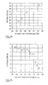
- Table 1 Parameters and suitable sensors Parameter Sensor Intake air mass flow Hot file air mass meter Fuel Lambda sensor Crankshaft position Inductive pick-up Camshaft position(s) Hall effect Exhaust gas temperature Thermocouple Intake manifold pressure Piezo Intake manifold temperature Thermocouple External EGR Stepper Motor position
- the electronic control unit 11 When operating in the CAI mode in regime 41, the electronic control unit 11 is operable to control the intake throttle 15 such that the engine 10 is running with the air pressure and temperature in the inlet manifold 16 at or near ambient pressure and temperature.
- the engine can be operated without heating of the inlet air.
- the inlet valve 19 and outlet valve 22 are controlled such that there is no overlap in opening between the valves and to retain exhaust gases within the cylinder 12, so called internal EGR.
- the valve lift was 4.5 mm and 160° crank angle duration to take account of sufficient gas trapping and valve train loading constraints. Variable valve times of 35° c.a. on the inlet valve camshaft and 55° c.a. on the outlet valve camshaft were available.
- the inlet cam timing was set to 140° c.a. TDC in the present example.
- the internal EGR may also be rebreathed from the outlet 17 as appropriate.
- the compression ratio is preferably in the range of about 8 to 14 and in this example 11.2:1, but may have any appropriate geometric compression ratio typical of those found in modem ignition engines.
- the external exhaust gas recirculation passes exhaust gases through the external recycling system 23 and the control valve 25.
- An effect of passing the exhaust gas through the external recycling system 23 to the inlet manifold 16 is to cool the recirculated exhaust gas, in particular where engine coolant is allowed to flow past the gas passage as in the present example.
- the air-to-fuel ratio ⁇ and the timing of the fuel injection By varying the proportions of exhaust gas recirculated through internal and external exhaust gas recirculation, together with control of the swirl control valve 27, the air-to-fuel ratio ⁇ and the timing of the fuel injection, the operation of the engine can be appropriately controlled.
- the addition of external EGR reduces the rate of heat release and thus inhibits knock by diluting the fuel/air/ retained or rebreathed exhaust gas mix within the cylinder 12.
- the proportions may be controlled by the electronic control unit 11 in accordance with the map 30 and in response to the values of the engine parameters received from the various sensors.
- Example methods of providing external EGR are shown in Table 2.
- the engine load and/or engine speed can be controlled by varying the proportion of exhaust gas recirculated to the cylinder 12.
- Table 2 Example methods of supplying external EGR Method Advantages Disadvantages Intake manifold throttling Negligible additional cost. Minimal engine pumping losses Small transient changes in intake manifold pressure have a large effect on CAI combustion (continual feedback required) Exhaust backpressure (via exhaust system) Negligible additional cost.
- Easier to implement than intake Insufficient EEGR flow at low speed may require small increase in throttling due to less influence on intake conditions backpressure, with increased engine pumping losses Exhaust backpressure (additional valve or restriction) Reduced pumping losses when EEGR not required. Increased engine pumping losses during CAI. Marginal on-cost deficit. Venturi in EEGR pipework Minimal additional cost. Limited increase in flow. EEGR pump (mechanical or electrical) Excellent control over EEGR flow Relatively high cost solution.
- the engine management unit needs to be able to detect and manage transitions, such as that shown from P 1 to P 2 in Figure 2.
- the engine control unit 11 receives information on engine operating parameters, including the engine parameters from the sensors plus possibly any demand from a driver of the vehicle or measured change in load.
- the electronic control unit 11 detects whether a mode transition is required, and if not, then at step 52 the electronic control unit 11 controls the exhaust gas recirculation and other aspects of the engine 10 in accordance with the detected parameters. If a transition is required, that is a change between operating modes is required or is predicted in response to the parameters, then at step 52 the transition step is performed.
- the transition step may include changing the relative timing and/or lift and/or duration of the opening and closing of the inlet valve 19 and outlet valve 22, such that the valves open and close to allow spark combustion operation, eg varied timing and/or increased duration and/or increased lift.
- the amount and proportion of EGR is reduced, with a particular reduction in external EGR allowing an additional degree of control over temperature within the cylinder 12 to avoid knocking.
- the transition should occur within a few engine cycles to avoid unwanted fluctuation in engine torque.
- the EGR mass should be varied with simultaneous variations in the intake air and/or fuel mass to avoid the engine running into a region of knock.
- spark-assisted CAI may be used as discussed above. It has been found that using external EGR can reduce the value of PK Max at a transition from spark ignition to CAI from about 3 bar to about 1.5 bar, and the external EGR varies from about 10% in SI operation to about 2% in CAI operation.
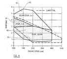
- FIG. 6 An illustration of the increase in operating range allowed by the engine is shown in reference to Figure 4 showing engine speed against load.
- the area 60 shows where lean burn controlled auto-ignition was employed at lower loads.
- the hatched area 61 shows where stoichiometric operation was achieved using internal EGR alone.
- region 62 this is the area of operation where controlled auto-ignition was delivered using combined IEGR and EEGR.
- the dashed outline 63 indicates the known regime in which controlled auto-ignition can occur. It will be apparent that by providing combined internal and external EGR, the available load of the engine under controlled auto-ignition can be increased. The greatest increase in available load was at point P 3 in this example.
- the load (plotted as gross mean effective pressure) which is generated using internal and external EGR is greater than that generated using internal EGR alone.
- the variation in the load using internal and external EGR is within a standard deviation of 0.2 over 300 engine cycles, representing a generally acceptable fluctuation.
- Figure 6c shows the peak knocking pressure. A peak knocking pressure of 1 bar is considered to be acceptable in terms of audible noise in an open test cell. Engine damage may occur at peak knocking pressures on the order of 4 bar and above.
- the peak knocking pressure under internal EGR alone reaches an unacceptable pressure, whilst the peak knocking pressure remains comparatively low throughout the regime using internal and external EGR. It is this suppression of knock that enables the increase in available load as shown in Figure 4.
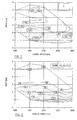
- Figures 7 to 10 show the control of various engine parameters over the whole of the operating ratio shown in Figure 4.
- the relative air-to-fuel regime over the operating regime is shown in Figure 7.
- ⁇ 1.4
- ⁇ can be in the range 0.8 to 2.5
- FIG 8 The swirl valve operating is shown in Figure 8.
- Figure 9 shows the timing of the fuel injection applied across the regime shown in Figure 4, optimised across the CAI map to achieve minimum emissions of NOx and the lowest valves of peak knocking pressure and improved combustion stability.
- the values of external EGR i.e. the proportion of the gas, air and fuel mix drawn into or supplied to the combustion chamber made of exhaust gases supplied by external EGR at an engine speed of 1500 rpm used are shown in Figure 10, with up to 10% external EGR being required at low speeds and higher loads, as shown in the example of point P 3 of Figure 4 above.
- the value of internal EGR i.e. the proportion of the gas, air and fuel mix drawn or supplied to the combustion chamber made up of exhaust gas supplied by internal EGR, can be in the range of 20% to 99% and more preferably at least 30% and less than 80%. In the example of Figure 5 a , internal EGR varies between 33% and 49%.
- the present invention may thus be cheaply and relatively easily applied to any appropriate internal combustion engine using any appropriate fuel, such as gasoline or a gasoline-like fuel such as a biofuel and alcohol, and may be useful in reducing fuel consumption and pollutant generation:
- any appropriate fuel such as gasoline or a gasoline-like fuel such as a biofuel and alcohol
Landscapes
- Engineering & Computer Science (AREA)
- Chemical & Material Sciences (AREA)
- Combustion & Propulsion (AREA)
- Mechanical Engineering (AREA)
- General Engineering & Computer Science (AREA)
- Output Control And Ontrol Of Special Type Engine (AREA)
- Combined Controls Of Internal Combustion Engines (AREA)
- Combustion Methods Of Internal-Combustion Engines (AREA)
- Electrical Control Of Air Or Fuel Supplied To Internal-Combustion Engine (AREA)
- Ignition Installations For Internal Combustion Engines (AREA)
- Exhaust-Gas Circulating Devices (AREA)
Applications Claiming Priority (2)
| Application Number | Priority Date | Filing Date | Title |
|---|---|---|---|
| GB0421682A GB0421682D0 (en) | 2004-09-30 | 2004-09-30 | Engine |
| GB0507153A GB0507153D0 (en) | 2005-04-08 | 2005-04-08 | Engine |
Publications (2)
| Publication Number | Publication Date |
|---|---|
| EP1643104A2 true EP1643104A2 (de) | 2006-04-05 |
| EP1643104A3 EP1643104A3 (de) | 2009-04-08 |
Family
ID=35394923
Family Applications (1)
| Application Number | Title | Priority Date | Filing Date |
|---|---|---|---|
| EP05021362A Withdrawn EP1643104A3 (de) | 2004-09-30 | 2005-09-30 | Motor |
Country Status (5)
| Country | Link |
|---|---|
| US (1) | US7263968B2 (de) |
| EP (1) | EP1643104A3 (de) |
| JP (1) | JP2006112424A (de) |
| KR (1) | KR20060051868A (de) |
| GB (1) | GB2418744B (de) |
Cited By (3)
| Publication number | Priority date | Publication date | Assignee | Title |
|---|---|---|---|---|
| EP1921294A2 (de) * | 2006-11-08 | 2008-05-14 | Iav Gmbh Ingenieurgesellschaft Auto Und Verkehr | Verfahren zur Betriebsartenumschaltung für eine Brennkraftmaschine |
| WO2008066202A1 (en) * | 2006-11-30 | 2008-06-05 | Kabushiki Kaisha Toyota Jidoshokki | Homogeneous charge compression ignition engine |
| EP2058499A3 (de) * | 2007-11-08 | 2014-08-06 | Hitachi Ltd. | Vorrichtung und Verfahren zur Steuerung eines Verbrennungsmotors mit homogener Kompressionszündung |
Families Citing this family (24)
| Publication number | Priority date | Publication date | Assignee | Title |
|---|---|---|---|---|
| US7228850B2 (en) * | 2005-08-12 | 2007-06-12 | Stant Manufacturing Inc. | Fuel vapor recovery canister |
| US7409946B2 (en) * | 2005-08-12 | 2008-08-12 | Stant Manufacturing Inc. | Fuel vapor recovery canister |
| US7472694B2 (en) * | 2005-11-08 | 2009-01-06 | Stant Manufacturing Inc. | Carbon canister with filter system |
| EP1918552B1 (de) * | 2006-10-24 | 2009-08-19 | Honda Motor Co., Ltd. | Internes EGR-Steuersystem für einen Verbrennungsmotor |
| US7461628B2 (en) * | 2006-12-01 | 2008-12-09 | Ford Global Technologies, Llc | Multiple combustion mode engine using direct alcohol injection |
| US8887691B2 (en) * | 2007-04-17 | 2014-11-18 | GM Global Technology Operations LLC | Method and apparatus for selecting a combustion mode for an internal combustion engine |
| US7540270B2 (en) * | 2007-04-24 | 2009-06-02 | Gm Global Technology Operations, Inc. | Method and apparatus for controlling combustion mode transitions in an internal combustion engine |
| US7412322B1 (en) * | 2007-07-27 | 2008-08-12 | Gm Global Technology Operations, Inc. | Method and apparatus for engine control during auto-ignition combustion |
| DE102008004365A1 (de) * | 2008-01-15 | 2009-07-16 | Robert Bosch Gmbh | Verfahren zum Betreiben eines Verbrennungsmotors, Computerprogramm und Steuergerät |
| US8490380B2 (en) * | 2008-01-17 | 2013-07-23 | Advanced Propulsion Technologies, Inc. | Internal continuous combustion engine system |
| JP5169439B2 (ja) * | 2008-04-24 | 2013-03-27 | 株式会社デンソー | 内燃機関制御装置及び内燃機関制御システム |
| US8776762B2 (en) * | 2009-12-09 | 2014-07-15 | GM Global Technology Operations LLC | HCCI mode switching control system and method |
| DE102011015629B4 (de) * | 2010-10-07 | 2020-12-24 | Daimler Ag | Betriebsverfahren einer Brennkraftmaschine |
| US9765658B2 (en) | 2011-03-02 | 2017-09-19 | Delphi Technologies, Inc. | Valve train system for an internal combustion engine |
| US9151240B2 (en) | 2011-04-11 | 2015-10-06 | GM Global Technology Operations LLC | Control system and method for a homogeneous charge compression ignition (HCCI) engine |
| US9051887B2 (en) | 2012-07-27 | 2015-06-09 | Caterpillar Inc. | System and method for adjusting fuel reactivity |
| US9151241B2 (en) | 2012-07-27 | 2015-10-06 | Caterpillar Inc. | Reactivity controlled compression ignition engine operating on a Miller cycle with low pressure loop exhaust gas recirculation system and method |
| US20140032081A1 (en) * | 2012-07-27 | 2014-01-30 | Caterpillar Inc. | Dual Mode Engine Using Two or More Fuels and Method for Operating Such Engine |
| US8991358B2 (en) | 2012-07-27 | 2015-03-31 | Caterpillar Inc. | Reactivity controlled compression ignition engine with exhaust gas recirculation |
| US9038582B2 (en) | 2012-07-27 | 2015-05-26 | Caterpillar Inc. | Split-cycle, reactivity controlled compression ignition engine and method |
| US9255550B2 (en) * | 2013-03-08 | 2016-02-09 | GM Global Technology Operations LLC | Emission system and method of selectively directing exhaust gas and air within an internal combustion engine |
| US9453481B2 (en) * | 2013-06-04 | 2016-09-27 | Ford Global Technologies, Llc | System and method for operating an engine |
| WO2018096586A1 (ja) * | 2016-11-22 | 2018-05-31 | マツダ株式会社 | 圧縮自己着火式エンジンの制御装置 |
| DE102018122342A1 (de) * | 2018-09-13 | 2020-03-19 | Man Truck & Bus Se | Verfahren zum Betreiben einer Brennkraftmaschine |
Citations (1)
| Publication number | Priority date | Publication date | Assignee | Title |
|---|---|---|---|---|
| US6286489B1 (en) * | 1998-12-11 | 2001-09-11 | Caterpillar Inc. | System and method of controlling exhaust gas recirculation |
Family Cites Families (15)
| Publication number | Priority date | Publication date | Assignee | Title |
|---|---|---|---|---|
| JP3680500B2 (ja) | 1997-07-02 | 2005-08-10 | 日産自動車株式会社 | 内燃機関の制御装置 |
| DE60019392T2 (de) * | 1999-12-14 | 2005-09-22 | Nissan Motor Co., Ltd., Yokohama | Ottobrennkraftmaschine mit Selbstzündung |
| JP3765216B2 (ja) * | 1999-12-14 | 2006-04-12 | 日産自動車株式会社 | 圧縮自己着火式ガソリン内燃機関 |
| US6295973B1 (en) | 1999-12-22 | 2001-10-02 | Ford Global Technologies, Inc. | Air-fuel charge controller for a homogeneous-charge, compression-ignition engine |
| US6497212B2 (en) | 2000-02-10 | 2002-12-24 | Denso Corporation | Control apparatus for a cylinder injection type internal combustion engine capable of suppressing undesirable torque shock |
| DE10009180C2 (de) * | 2000-02-26 | 2002-04-25 | Daimler Chrysler Ag | Verfahren zur Erzeugung eines homogenen Gemischs für selbstzündende Brennkraftmaschinen und zur Steuerung des Verbrennungsprozesses |
| JP2001248484A (ja) | 2000-02-29 | 2001-09-14 | Hitachi Ltd | 筒内噴射エンジン及びその制御装置,制御方法 |
| JP2001323828A (ja) * | 2000-05-16 | 2001-11-22 | Nissan Motor Co Ltd | 圧縮自己着火式ガソリン機関 |
| JP3880296B2 (ja) * | 2000-08-02 | 2007-02-14 | 株式会社日立製作所 | エンジンの制御装置 |
| JP3945152B2 (ja) * | 2000-11-21 | 2007-07-18 | 日産自動車株式会社 | 内燃機関の燃焼制御装置 |
| ITTO20010660A1 (it) * | 2001-07-06 | 2003-01-06 | Fiat Ricerche | Motore diesel pluricilindrico con azionamento variabile delle valvole. |
| JP4144251B2 (ja) | 2002-05-09 | 2008-09-03 | トヨタ自動車株式会社 | 内燃機関における排気環流の制御 |
| JP2003328757A (ja) * | 2002-05-14 | 2003-11-19 | Fuji Heavy Ind Ltd | 筒内噴射エンジンの制御装置 |
| JP4126971B2 (ja) * | 2002-06-27 | 2008-07-30 | トヨタ自動車株式会社 | 混合気を圧縮自着火させて運転する内燃機関、および内燃機関の制御方法 |
| JP2005090468A (ja) * | 2003-09-22 | 2005-04-07 | Toyota Industries Corp | 予混合圧縮自着火内燃機関のegr装置、および、予混合圧縮自着火内燃機関の着火時期制御方法 |
-
2005
- 2005-09-29 US US11/238,216 patent/US7263968B2/en not_active Expired - Fee Related
- 2005-09-29 GB GB0519784A patent/GB2418744B/en not_active Expired - Fee Related
- 2005-09-29 KR KR1020050091485A patent/KR20060051868A/ko not_active Application Discontinuation
- 2005-09-30 EP EP05021362A patent/EP1643104A3/de not_active Withdrawn
- 2005-09-30 JP JP2005286952A patent/JP2006112424A/ja active Pending
Patent Citations (1)
| Publication number | Priority date | Publication date | Assignee | Title |
|---|---|---|---|---|
| US6286489B1 (en) * | 1998-12-11 | 2001-09-11 | Caterpillar Inc. | System and method of controlling exhaust gas recirculation |
Non-Patent Citations (1)
| Title |
|---|
| ALLEN J.; LAW D.: "Variable Valve Actuated Controlled Auto-Ignition", SPEED LOAD MAPS AND STRATEGIC REGIMES OF OPERATION |
Cited By (4)
| Publication number | Priority date | Publication date | Assignee | Title |
|---|---|---|---|---|
| EP1921294A2 (de) * | 2006-11-08 | 2008-05-14 | Iav Gmbh Ingenieurgesellschaft Auto Und Verkehr | Verfahren zur Betriebsartenumschaltung für eine Brennkraftmaschine |
| EP1921294A3 (de) * | 2006-11-08 | 2012-04-04 | IAV GmbH Ingenieurgesellschaft Auto und Verkehr | Verfahren zur Betriebsartenumschaltung für eine Brennkraftmaschine |
| WO2008066202A1 (en) * | 2006-11-30 | 2008-06-05 | Kabushiki Kaisha Toyota Jidoshokki | Homogeneous charge compression ignition engine |
| EP2058499A3 (de) * | 2007-11-08 | 2014-08-06 | Hitachi Ltd. | Vorrichtung und Verfahren zur Steuerung eines Verbrennungsmotors mit homogener Kompressionszündung |
Also Published As
| Publication number | Publication date |
|---|---|
| KR20060051868A (ko) | 2006-05-19 |
| US20060102158A1 (en) | 2006-05-18 |
| JP2006112424A (ja) | 2006-04-27 |
| US7263968B2 (en) | 2007-09-04 |
| GB2418744A (en) | 2006-04-05 |
| EP1643104A3 (de) | 2009-04-08 |
| GB0519784D0 (en) | 2005-11-09 |
| GB2418744B (en) | 2009-04-01 |
Similar Documents
| Publication | Publication Date | Title |
|---|---|---|
| US7263968B2 (en) | Exhaust gas recirculation | |
| AU2003224703B2 (en) | Controlled temperature combustion engine | |
| US6990947B2 (en) | Homogeneous charge compression ignition engine and method for operating homogeneous charge compression ignition engine | |
| US6516774B2 (en) | Premixed charge compression ignition engine with variable speed SOC control and method of operation | |
| US6983730B2 (en) | Homogeneous charge compression ignition engine and method for operating homogeneous charge compression ignition engine | |
| US7363911B2 (en) | Humidity-based combustion control in a multiple combustion mode engine | |
| US6978771B2 (en) | Homogeneous charge compression ignition engine and method for operating homogeneous charge compression ignition engine | |
| EP2264303B1 (de) | Steuerungsverfahren und Motorvorrichtung und entsprechender Motor | |
| US20100077990A1 (en) | Control of spark ignited internal combustion engine | |
| US7866148B2 (en) | Combustion control utilizing exhaust throttling | |
| US7703442B2 (en) | Method for operating an internal combustion engine | |
| JP3690078B2 (ja) | 火花点火エンジン | |
| US20200191087A1 (en) | Premixed compression ignition type engine with supercharging system | |
| KR101029142B1 (ko) | 점화 타이밍 제어 방법, 점화 타이밍 지체 방법, 및 제품 | |
| JP2001506722A (ja) | 直接噴射式の内燃機関の制御方法 | |
| US20200182175A1 (en) | Compression ignition engine | |
| JP4180995B2 (ja) | 圧縮着火内燃機関の制御装置 | |
| JP2002188468A (ja) | ディーゼルエンジンの燃焼制御装置 | |
| JP4098684B2 (ja) | 圧縮着火内燃機関の制御装置 | |
| JP7282312B2 (ja) | 燃料噴射量の学習制御方法 | |
| JP7282311B2 (ja) | 燃料噴射量の学習制御方法 | |
| JP7380150B2 (ja) | エンジンの制御装置 | |
| JP4801744B2 (ja) | 内燃機関の運転方法および装置 | |
| JP2019052607A (ja) | オゾン添加システム |
Legal Events
| Date | Code | Title | Description |
|---|---|---|---|
| PUAI | Public reference made under article 153(3) epc to a published international application that has entered the european phase |
Free format text: ORIGINAL CODE: 0009012 |
|
| AK | Designated contracting states |
Kind code of ref document: A2 Designated state(s): AT BE BG CH CY CZ DE DK EE ES FI FR GB GR HU IE IS IT LI LT LU LV MC NL PL PT RO SE SI SK TR |
|
| AX | Request for extension of the european patent |
Extension state: AL BA HR MK YU |
|
| PUAL | Search report despatched |
Free format text: ORIGINAL CODE: 0009013 |
|
| AK | Designated contracting states |
Kind code of ref document: A3 Designated state(s): AT BE BG CH CY CZ DE DK EE ES FI FR GB GR HU IE IS IT LI LT LU LV MC NL PL PT RO SE SI SK TR |
|
| AX | Request for extension of the european patent |
Extension state: AL BA HR MK YU |
|
| 17P | Request for examination filed |
Effective date: 20091006 |
|
| AKX | Designation fees paid |
Designated state(s): AT BE BG CH CY CZ LI |
|
| 17Q | First examination report despatched |
Effective date: 20091118 |
|
| RBV | Designated contracting states (corrected) |
Designated state(s): AT BE BG CH CY CZ DE DK EE ES FI FR GB GR HU IE IS IT LI LT LU LV MC NL PL PT RO SE SI SK TR |
|
| REG | Reference to a national code |
Ref country code: DE Ref legal event code: 8566 |
|
| STAA | Information on the status of an ep patent application or granted ep patent |
Free format text: STATUS: THE APPLICATION IS DEEMED TO BE WITHDRAWN |
|
| 18D | Application deemed to be withdrawn |
Effective date: 20170621 |