EP1642401B1 - Verfahren und vorrichtung zur diversitätsumschaltung von empfangsantennen - Google Patents
Verfahren und vorrichtung zur diversitätsumschaltung von empfangsantennen Download PDFInfo
- Publication number
- EP1642401B1 EP1642401B1 EP04737888A EP04737888A EP1642401B1 EP 1642401 B1 EP1642401 B1 EP 1642401B1 EP 04737888 A EP04737888 A EP 04737888A EP 04737888 A EP04737888 A EP 04737888A EP 1642401 B1 EP1642401 B1 EP 1642401B1
- Authority
- EP
- European Patent Office
- Prior art keywords
- antenna
- signal strength
- diversity
- data packet
- preamble
- Prior art date
- Legal status (The legal status is an assumption and is not a legal conclusion. Google has not performed a legal analysis and makes no representation as to the accuracy of the status listed.)
- Expired - Lifetime
Links
- 238000000034 method Methods 0.000 title claims abstract description 29
- 238000004891 communication Methods 0.000 claims abstract description 13
- 238000005259 measurement Methods 0.000 claims description 15
- 238000012545 processing Methods 0.000 claims description 7
- 230000008569 process Effects 0.000 claims description 5
- 230000003068 static effect Effects 0.000 claims description 3
- 230000005540 biological transmission Effects 0.000 abstract description 7
- 238000010586 diagram Methods 0.000 description 8
- 238000013461 design Methods 0.000 description 6
- 230000004044 response Effects 0.000 description 5
- 230000008901 benefit Effects 0.000 description 4
- 238000004590 computer program Methods 0.000 description 4
- 238000012935 Averaging Methods 0.000 description 2
- 230000009471 action Effects 0.000 description 2
- 230000000052 comparative effect Effects 0.000 description 2
- 238000001514 detection method Methods 0.000 description 2
- 238000004091 panning Methods 0.000 description 2
- 238000005070 sampling Methods 0.000 description 2
- 230000001960 triggered effect Effects 0.000 description 2
- 101100420681 Caenorhabditis elegans tir-1 gene Proteins 0.000 description 1
- 230000002411 adverse Effects 0.000 description 1
- 230000009286 beneficial effect Effects 0.000 description 1
- 238000006243 chemical reaction Methods 0.000 description 1
- 238000012937 correction Methods 0.000 description 1
- 230000007812 deficiency Effects 0.000 description 1
- 230000006735 deficit Effects 0.000 description 1
- 230000001419 dependent effect Effects 0.000 description 1
- 230000006866 deterioration Effects 0.000 description 1
- 229920005994 diacetyl cellulose Polymers 0.000 description 1
- 230000000694 effects Effects 0.000 description 1
- 238000005562 fading Methods 0.000 description 1
- 238000001914 filtration Methods 0.000 description 1
- 230000006870 function Effects 0.000 description 1
- 230000003116 impacting effect Effects 0.000 description 1
- 230000006872 improvement Effects 0.000 description 1
- 238000012986 modification Methods 0.000 description 1
- 230000004048 modification Effects 0.000 description 1
- 230000003287 optical effect Effects 0.000 description 1
- 238000011084 recovery Methods 0.000 description 1
- 239000004065 semiconductor Substances 0.000 description 1
- 230000035945 sensitivity Effects 0.000 description 1
- 230000005236 sound signal Effects 0.000 description 1
- 230000001629 suppression Effects 0.000 description 1
Images




Classifications
-
- H—ELECTRICITY
- H04—ELECTRIC COMMUNICATION TECHNIQUE
- H04B—TRANSMISSION
- H04B7/00—Radio transmission systems, i.e. using radiation field
- H04B7/02—Diversity systems; Multi-antenna system, i.e. transmission or reception using multiple antennas
- H04B7/04—Diversity systems; Multi-antenna system, i.e. transmission or reception using multiple antennas using two or more spaced independent antennas
- H04B7/08—Diversity systems; Multi-antenna system, i.e. transmission or reception using multiple antennas using two or more spaced independent antennas at the receiving station
- H04B7/0802—Diversity systems; Multi-antenna system, i.e. transmission or reception using multiple antennas using two or more spaced independent antennas at the receiving station using antenna selection
- H04B7/0805—Diversity systems; Multi-antenna system, i.e. transmission or reception using multiple antennas using two or more spaced independent antennas at the receiving station using antenna selection with single receiver and antenna switching
- H04B7/0808—Diversity systems; Multi-antenna system, i.e. transmission or reception using multiple antennas using two or more spaced independent antennas at the receiving station using antenna selection with single receiver and antenna switching comparing all antennas before reception
- H04B7/0811—Diversity systems; Multi-antenna system, i.e. transmission or reception using multiple antennas using two or more spaced independent antennas at the receiving station using antenna selection with single receiver and antenna switching comparing all antennas before reception during preamble or gap period
-
- H—ELECTRICITY
- H04—ELECTRIC COMMUNICATION TECHNIQUE
- H04B—TRANSMISSION
- H04B7/00—Radio transmission systems, i.e. using radiation field
- H04B7/02—Diversity systems; Multi-antenna system, i.e. transmission or reception using multiple antennas
- H04B7/04—Diversity systems; Multi-antenna system, i.e. transmission or reception using multiple antennas using two or more spaced independent antennas
- H04B7/08—Diversity systems; Multi-antenna system, i.e. transmission or reception using multiple antennas using two or more spaced independent antennas at the receiving station
- H04B7/0802—Diversity systems; Multi-antenna system, i.e. transmission or reception using multiple antennas using two or more spaced independent antennas at the receiving station using antenna selection
- H04B7/0805—Diversity systems; Multi-antenna system, i.e. transmission or reception using multiple antennas using two or more spaced independent antennas at the receiving station using antenna selection with single receiver and antenna switching
- H04B7/0814—Diversity systems; Multi-antenna system, i.e. transmission or reception using multiple antennas using two or more spaced independent antennas at the receiving station using antenna selection with single receiver and antenna switching based on current reception conditions, e.g. switching to different antenna when signal level is below threshold
Definitions
- the invention relates to the field of wireless communications, more particularly to a method of and device for switching between antennae communicating with a diversity receiver, each of the antennae receiving signals transmitted from a single source.
- a common problem in wireless communications is interference caused by nearby transmissions on the same or adjacent frequency bands. Interference can cause a receiver to misinterpret a transmitted signal, become jammed, fail to correlate a received signal, or can have other adverse effects on the ability of a receiver to properly receive transmitted information.
- receivers in a wireless communication system can also suffer from multipath and fading, which can cause the received signal to fluctuate in amplitude, phase or other characteristics in a relatively short period of time.
- Dropouts occur when the transmitter and receiver antennas are in a particular location relative to one another. As shown in Figure 1 , the signal from the transmitter 10 reaches antenna A of receiver 12 via a direct path and a reflected path. The reflected signal path is a bit longer than the direct path, causing the two signals to be put out of phase when they mix together at the receiver antenna A. The resulting weak signal causes a dropout. Moving the transmitter 10 or receiver 12 to a different location may reduce or eliminate dropouts. However, sometimes relocating these devices is not practical or possible. As a result antenna diversity techniques were developed to overcome dropouts.
- antenna diversity The basic concept of antenna diversity is depicted in Figure 2 .
- two antennas A and B are used.
- the signal arriving from transmitter 10 at antenna A is largely cancelled by a multipath null, leaving little signal left for the diversity receiver 14;
- the signal at antenna B remains strong and provides adequate signal for the receiver 12 to produce a usable audio signal to noise ratio.
- the spacing between antennas A and B must be at least 1 ⁇ 2 wavelength of the operating frequency to ensure that antennas A and B are receiving uncorrelated (i.e. "Diverse") signals to gain the full benefit of diversity reception.
- the signals received from antennas A and B are processed in a diversity receiver 14.
- Diversity circuitry implemented in a high quality receiver with excellent sensitivity will reduce or eliminate multipath dropouts and, in some cases, increase operating range.
- the improvement in reception will vary depending upon the diversity methodology chosen by the designer.
- the type of diversity reception circuitry chosen in the receiver design includes a number of considerations, including cost, size and weight, performance and the practicality of each circuit type for a given application.
- the manner in which incoming signals from two different antennas are handled after they enter the receiver is what makes the difference between a highly efficient and a less efficient receiver. Using diversity reception makes little sense unless the receiver is a high quality design to begin with.
- non-active is a non-active technique which involves the addition of a second antenna to a single receiver, placed 1 ⁇ 2 wavelength or more away.
- the antennas A and B are connected to a combiner 16 which adds the two signals. However, when the received signals are out of phase with one another dropouts will occur.
- active diversity reception techniques include: antenna phase switching diversity; audio switching diversity; and ratio diversity.
- antenna phase switching diversity two antennas A and B are mixed to feed a single combiner 16 , with a phase reversal switch (not shown) added to the input of one of the antennae.
- logic circuitry 18 determines whether or not the switching action has improved the signal to noise ratio, and decides whether to latch in that position or switch and sample again.
- the problem with this solution is that the receiver doesn't react until it is already in trouble. Further, there is always the possibility that switching phase will make a marginal problem worse.
- the switching circuitry since the switching circuitry is in the RF signal path and is triggered only at RF levels, it can produce a "click" when the switching occurs.
- audio switching diversity uses two receivers 20, 22, selecting the audio output of one of the receivers.
- the switching action is usually triggered by comparing incoming RF levels and switching to the receiver with the stronger RF signal, which usually produces a better signal to noise ratio in multipath conditions.
- the downside of this solution is that two receivers are required, meaning that the physical size and power requirements will be greater. In order to implement this solution in a compact, battery powered receiver, serious compromises must be made in the circuit design to reduce the physical size and power requirements.
- ratio diversity utilizes two separate receivers 20,22, sharing a common oscillator and audio circuitry.
- the audio inputs of the receivers are used simultaneously, being mixed by a "panning" circuit 24 in a ratio controlled by the comparative RF levels at the receivers 20, 22.
- This method anticipates dropouts long before they occur, since the comparative RF level sampling and mixing starts taking place at higher RF signal levels than in other diversity designs. By the time the signal level at one receiver drops low enough to produce noise, the panning circuitry 24 has long since shifted to the other receiver.
- a ratio diversity receiver utilizes both receivers simultaneously.
- the ratio diversity receiver will continue to balance the outputs of the two receivers for the lowest noise, even at very low RF levels.
- two receivers are required, resulting in the same disadvantages.
- diversity receivers select the antenna to be used for each individual burst based on a metric that is measured during the beginning of each received burst or packet.
- a metric that is measured during the beginning of each received burst or packet.
- fast diversity decisions require a low latency filter, but such a filter may not reject noise and interference very well. This is a tradeoff decision impacting the performance of the diversity algorithm. Allowing for high latency enables the design of a filter that has better noise to interference rejection which is beneficial during data transmission after the header where latency is less of a concern.
- the metric upon which the antenna selection is based can either be a signal quality index or a signal power index.
- Signal quality indices will often use a matched filter to generate the decision metric.
- the timing budget may not allow for a reliable signal quality index to be generated for all antennae.
- the signal power index is a preferred alternative since it takes less time to measure.
- the use of the signal power index in has not been efficiently incorporated into a diversity selection receiver to date.
- US 2003/0119468 A1 discloses an apparatus with a first antenna configured to receive the beginning portion of a preamble header information, and a second antenna configured to receive the remaining portion of the preamble header information.
- Mean-Squared Errors are calculated for each antenna.
- the antenna with the lower MSE is selected for receiving and processing the rest of incoming data packets.
- the MSE of the first antenna is greater than a predetermined threshold value, an antenna switching to the second antenna will occur.
- US 6,483,884 B1 discloses a preamble diversity switching method.
- the method involves measuring the receive signal strength of a diversity of antennas at the beginning of each extended preamble.
- the receive signal levels of each antenna which are the Receive Signal Strength Indicators (RSSI) are stored and compared.
- the antenna with the higher RSSI value is selected.
- RSSI values are determined for each antenna, and the antenna having the highest RSSI value is selected only if a RSSI difference signal is greater than or equal to a threshold value.
- the advantages of the present invention are readily apparent.
- the invention allows the benefit of per packet antenna diversity selection within a tighter timing budget.
- a tighter timing budget allows more of the preamble to be used for other processing once the preferred antenna has been selected, without storing parts of the packet to combat latency. Ultimately more efficient transmission of packets is achieved.
- the invention describes a technique for selecting between two receiver antennae in a wireless communications system utilizing a single receiver.
- the invention provides for the sampling of the signal strength during receipt of the preamble of a packet, and making an antenna selection based on the determined signal strength.
- the preferred receiver may be, for example, the ICE5350 Digital Receiver offered by IceFyre Semiconductor Inc. but the invention is not meant to be limited to this receiver.
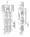
- the diversity receiver is located between the RF Receiver Front End 28 and the Physical Medium Access Control (PHY/MAC) 30.
- the RF Receiver Front End connects to antennae A and B.
- the two main blocks within the diversity receiver 26 are the digital demodulator 32 and the baseband decoder 34.
- the digital demodulator 32 recovers the baseband signal by removing carrier offsets, timing offsets, compensating for the channel impairments and demapping the digitally modulated signal.
- This block is located between the analog-to-digital interface (not shown) and the baseband interface (not shown).
- the baseband decoder 34 de-interleaves the baseband signal, provides error correction through the soft-decision Viterbi algorithm and unscrambles the corrected bit stream to be passed through the PHY/MAC 32.
- This block is located between the baseband interface (not shown) and the PHY/MAC interface (not shown).
- FIG. 5 depicts the digital demodulator 32 of Figure 4 .
- the analog to digital interface is located at block ADCs/ DACs 36.
- the baseband interface can also be seen in the figure at the soft decision demapper 38.
- the digital demodulator 32 is distinctly divided into two parts by the Fast Fourier Transform (FFT) circuit 40.
- FFT Fast Fourier Transform
- DFE digital demodulator front-end
- DBE digital demodulator back-end
- the invention of the present invention is provided in the digital demodulator front-end 42.
- Figure 6 depicts the digital demodulator front-end 42 of Figure 5 .
- the blocks and 'wires' that are in bold are those that are in use during the diversity selection process and are defined as follows:
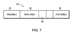
- FIG. 7 depicts a typical packet generated in a packet generation circuit of a transmitter communicating with diversity receiver 26.
- each of the packets 60 comprise a preamble section 62, a data section 64 and an (optional) postamble section 66.
- the preamble section 62 is used for, among other things, synchronization which allows the receiver to perform such functions as clock recovery, automatic gain control, signal-to-noise ratio estimation and diversity selection which is the focus of the present invention.
- the preamble may also contain a start of frame delimiter, and a data rate field indicating the data rate which will be used for the reception of the data section 64.
- the postamble section 66 generally contains an end of frame delimiter and optionally an error detection code such as, for example, a cyclical redundancy check (CRC) code.
- CRC cyclical redundancy check
- a packet may contain an additional "midamble” section, which is sometimes placed in the middle of a very large packet. It basically contains some preamble-like information to assist in timing and frequency tracking/reacquisition. It may be possible to use the "midamble" for an additional diversity selection in mid packet and this is meant to be included within the scope of the invention
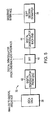
- the diversity select circuit integral to the invention will now be described in relation to Figure 8 .
- the diversity select circuit is set to default to antenna A (see Figure 4 ).
- a transmitted packet is received by antennae A and B of the diversity receiver 26.
- a packet detection circuit (not shown) in the digital demodulator front-end 42 determines that a packet, in the form of a signal on a carrier wave, has been detected by the current antenna (i.e. the default antenna A). If a packet is not detected, the circuit returns to an idle state and awaits the receipt of a future signal. If a packet is detected, at step 102, the gain and DDCO settings are frozen to ensure that the circuit has common state settings for the power/RSSI measurement of antennae A (and subsequently antenna B if required).
- the power/RSSI of the antenna A signal is then measured (at step 104) during a first sample time.
- the power/RSSI measurement is then compared with Thr_Great, a user selected threshold to determine if the signal strength of the detected packet is of sufficient strength to be processed.
- the diversity circuit signals that a packet of sufficient signal strength has been detected, and Antenna A is selected for the duration of the packet receipt.
- antenna B is selected and at step 112 a power/RSSI measurement is taken.
- the antenna B measurement is compared with the measurement from antenna A. If the antenna B measurement is greater than the antenna A measurement, circuit selects antenna B (step 116). If the antenna B measurement is not greater than the antenna A measurement then the circuit defaults to antenna A. Where antenna B has been selected, after the packet has been received, the circuit switches back to the default antenna A.
- the arithmetic average of the received signal power over a given period of the preamble of each antenna is calculated at the Pwr Block Avg 54 shown in Figure 6 .
- the period is selected such that for an ideal signal the average power will be time- independent i.e. if the average starts on sample n, it will equal the same as if the average started on sample m, where n and m are not equal.
- the period is selected such that there is sufficient noise suppression i.e. the variance of the average on a noisy signal is reduced.
- the signal is examined after fast (i.e.
- Finite Impulse Response FIR
- IIR Infinite Impulse Response
- the present invention may be implemented as a combination of both hardware and software.
- the present invention can be implemented as a series of computer readable instructions stored in a microprocessor - a digital signal processor (DSP) ideally suited to the numerically-intensive requirements of diversity selection.
- the computer-readable instructions may be programed in a procedural programming language (e.g. "C") or an object oriented language (e.g. "C++").
- C procedural programming language
- object oriented language e.g. "C++”
- Embodiments of the present invention may also be implemented as a computer program product for use with a computer system.
- Such implementation may include a series of computer instructions fixed either on a tangible medium, such as a computer readable medium (e . g ., a diskette, CD-ROM, ROM, or fixed disk) or transmittable to a computer system, via a modem or other interface device, such as a communications adapter connected to a network over a medium.
- the medium may be either a tangible medium (e . g ., optical or electrical communications lines) or a medium implemented with wireless techniques ( e . g ., microwave, infrared or other transmission techniques).
- Such a computer program product may be distributed as a removable medium with accompanying printed or electronic documentation (e . g ., shrink wrapped software), preloaded with a computer system ( e . g ., on system ROM or fixed disk), or distributed from a server over the network ( e . g ., the Internet or World Wide Web).
- a computer system e . g ., on system ROM or fixed disk
- a server e. g ., the Internet or World Wide Web
- some embodiments of the invention may be implemented as a combination ofboth software ( e . g ., a computer program product) and hardware.
- Still other embodiments of the invention may be implemented entirely as hardware, or entirely software ( e . g ., a computer program product).
Landscapes
- Engineering & Computer Science (AREA)
- Computer Networks & Wireless Communication (AREA)
- Signal Processing (AREA)
- Radio Transmission System (AREA)
- Mobile Radio Communication Systems (AREA)
Claims (10)
- Verfahren zum Auswählen einer Antenne von mindestens zwei Antennen (A, B) auf paketweiser Basis, wobei das Verfahren zur Verwendung in einem Drahtlos-Kommunikationssystem angepasst ist, wobei das Verfahren beinhaltet:(a) bei jeder der mindestens zwei Antennen (A, B), die mit einem Diversitätsempfänger (26) kommunizieren, wird ein Datenpaket (60) empfangen, das über eine Drahtlos-Kommunikationsverbindung gesendet worden ist, wobei das Datenpaket mindestens eine Präambel (62) aufweist, die eine Signalstärke aufweist;(b) die einer ersten Antenne (A) zugehörige Signalstärke der Datenpaket-Präambel wird bestimmt;(c) die erste Antenne (A) wird ausgewählt, falls die bestimmte Signalstärke einen vorbestimmten Schwellenwert überschreitet;(d) falls die der ersten Antenne (A) zugehörige Signalstärke der Datenpaket-Präambel den vorbestimmten Schwellenwert nicht übersteigt, dann:(d1) die einer zweiten Antenne (B) zugehörige Signalstärke der Datenpaket-Präambel wird bestimmt;(d2) die der zweiten Antenne (B) zugehörige Signalstärke der Datenpaket-Präambel wird mit der der ersten Antenne (A) zugehörigen Signalstärke der Datenpaket-Präambel verglichen; und(d3) es wird die zweite Antenne (B) ausgewählt, falls die der zweiten Antenne (B) zugehörige Signalstärke der Datenpaket-Präambel größer als die der ersten Antenne (A) zugehörige Signalstärke der Datenpaket-Präambel ist, und sonst wird die ersten Antenne (A) ausgewählt.
- Verfahren nach Anspruch 1,bei dem die Bestimmung nach einer Verarbeitung durch ein geringe Latenz aufweisendes Filter (48) erfolgt;wobei die Bestimmung vor Verarbeitung durch ein hohe Latenz aufweisendes Filter erfolgt; undwobei das hohe Latenz aufweisende Filter verwendet wird, um den Rest des empfangenen Datenpaketes zu verarbeiten.
- Verfahren nach Anspruch 1 oder Anspruch 2, bei dem der Schritt des Bestimmens beinhaltet, dass der arithmetische Mittelwert der Signalstärke über einen benutzerdefinierten Zeitraum der Datenpaket-Präambel (62) berechnet wird.
- Verfahren nach Anspruch 3, bei dem der benutzerdefinierte Zeitraum derart gewählt wird, dass die berechnete Durchschnittssignalstärke zeitunabängig ist.
- Verfahren nach Anspruch 1, welches weiter den Schritt beinhaltet, dass eine der mindestens zwei Antennen (A, B) basierend auf einer Messung einer Signalstärke einer Midamble ausgewählt wird, die dem empfangenen Datenpaket zugehörig ist.
- Verfahren nach Anspruch 1, bei dem eine digitale Gleichstromkomponente und eine Verstärkungskomponente während des Bestimmungsschrittes statisch bleiben.
- Diversitätsempfänger (26), der für eine Verwendung in einem Drahtlos-Netzwerk angepasst ist, um zwischen einer von mindestens zwei Antennen (A, B) auf paketweiser Basis auszuwählen, wobei der Diversitätsempfänger (26) aufweist:(a) mindestens zwei Antennen (A, B); und(b) eine Diversitätswahlschaltung, die mit den mindestens zwei Antennen (A, B) kommuniziert,wobei der Diversitätsempfänger (26) ausgebildet ist, um das Verfahren nach einem der Ansprüche 1 bis 6 durchzuführen,
wobei die Diversitätswahlschaltung fähig ist, eine der mindestens zwei Antennen (A, B) basierend auf einer Signalstärke auszuwählen, die einer Präambel (62) eines Paketes (60) zugehörig ist, das über eine Drahtlos-Kommunikationsverbindung empfangen wird. - Diversitätsempfänger (26) nach Anspruch 7,bei dem die Diversitätswahlschaltung weiter ein geringe Latenz aufweisendes Filter beinhaltet;
wobei die Signalstärke, die der Präambel (62) zugehörig ist, nach Verarbeitung durch das geringe Latenz aufweisende Filter überprüft wird; und
wobei die Präambel (62) vor Verarbeiten durch ein hohe Latenz aufweisendes Filter überprüft wird, und wobei das hohe Latenz aufweisende Filter verwendet wird, um den Rest des empfangenen Datenpaketes zu verarbeiten. - Diversitätsempfänger (26) nach Anspruch 7 oder Anspruch 8, bei dem die Diversitätswahlschaltung zwischen einer der mindestens zwei Antennen (A, B) basierend auf einer Metrik auswählt, die einer Midamble des empfangenen Paketes zugehörig ist.
- Diversitätsempfänger (26) nach Anspruch 7 oder Anspruch 8, bei dem die Diversitätswahlschaltung weiter eine digitale Gleichstrom-Kompensationskomponente und eine Verstärkungskomponente aufweist, und wobei diese Komponenten während der Operation der Diversitätsauswahlkomponente statisch bleiben.
Applications Claiming Priority (2)
| Application Number | Priority Date | Filing Date | Title |
|---|---|---|---|
| US10/610,454 US7359692B2 (en) | 2003-06-30 | 2003-06-30 | Method of and device for antennae diversity switching |
| PCT/CA2004/000949 WO2005002084A1 (en) | 2003-06-30 | 2004-06-23 | A method of and device for receive antennae diversity switching |
Publications (2)
| Publication Number | Publication Date |
|---|---|
| EP1642401A1 EP1642401A1 (de) | 2006-04-05 |
| EP1642401B1 true EP1642401B1 (de) | 2008-12-17 |
Family
ID=33541152
Family Applications (1)
| Application Number | Title | Priority Date | Filing Date |
|---|---|---|---|
| EP04737888A Expired - Lifetime EP1642401B1 (de) | 2003-06-30 | 2004-06-23 | Verfahren und vorrichtung zur diversitätsumschaltung von empfangsantennen |
Country Status (7)
| Country | Link |
|---|---|
| US (2) | US7359692B2 (de) |
| EP (1) | EP1642401B1 (de) |
| JP (1) | JP4823058B2 (de) |
| CN (1) | CN1883134B (de) |
| AT (1) | ATE418188T1 (de) |
| DE (1) | DE602004018498D1 (de) |
| WO (1) | WO2005002084A1 (de) |
Families Citing this family (57)
| Publication number | Priority date | Publication date | Assignee | Title |
|---|---|---|---|---|
| US6496543B1 (en) | 1996-10-29 | 2002-12-17 | Qualcomm Incorporated | Method and apparatus for providing high speed data communications in a cellular environment |
| US7483483B2 (en) * | 2001-12-06 | 2009-01-27 | Pulse-Link, Inc. | Ultra-wideband communication apparatus and methods |
| US7174138B2 (en) | 2003-08-21 | 2007-02-06 | Conexant Systems, Inc. | Power-based hardware diversity |
| DE602004016208D1 (de) * | 2003-10-15 | 2008-10-09 | Matsushita Electric Industrial Co Ltd | Diversitäts-empfangsvorrichtung und dieselbe verwendende drahtlose empfangsvorrichtung |
| US6990324B2 (en) * | 2004-04-15 | 2006-01-24 | Flarion Technologies, Inc. | Methods and apparatus for selecting between multiple carriers using a single receiver chain tuned to a single carrier |
| US7525926B2 (en) * | 2004-08-02 | 2009-04-28 | Atheros Communications, Inc. | Wireless communication using beam forming and diversity |
| US7801235B2 (en) * | 2004-08-30 | 2010-09-21 | Intel Corporation | Method and apparatus for achieving multiple antenna diversity with two antenna per packet diversity in a wireless network |
| US7327803B2 (en) | 2004-10-22 | 2008-02-05 | Parkervision, Inc. | Systems and methods for vector power amplification |
| US7355470B2 (en) | 2006-04-24 | 2008-04-08 | Parkervision, Inc. | Systems and methods of RF power transmission, modulation, and amplification, including embodiments for amplifier class transitioning |
| CN100355308C (zh) * | 2005-07-21 | 2007-12-12 | 上海交通大学 | 三扇区正交频分复用无线蜂窝网络中的频率复用方法 |
| US8334722B2 (en) | 2007-06-28 | 2012-12-18 | Parkervision, Inc. | Systems and methods of RF power transmission, modulation and amplification |
| US7911272B2 (en) | 2007-06-19 | 2011-03-22 | Parkervision, Inc. | Systems and methods of RF power transmission, modulation, and amplification, including blended control embodiments |
| US8013675B2 (en) | 2007-06-19 | 2011-09-06 | Parkervision, Inc. | Combiner-less multiple input single output (MISO) amplification with blended control |
| JP2007159079A (ja) * | 2005-12-02 | 2007-06-21 | Pantech Co Ltd | 移動通信端末機の自動感度補償方法および前記移動通信端末機 |
| US7937106B2 (en) | 2006-04-24 | 2011-05-03 | ParkerVision, Inc, | Systems and methods of RF power transmission, modulation, and amplification, including architectural embodiments of same |
| US8031804B2 (en) | 2006-04-24 | 2011-10-04 | Parkervision, Inc. | Systems and methods of RF tower transmission, modulation, and amplification, including embodiments for compensating for waveform distortion |
| US8315336B2 (en) | 2007-05-18 | 2012-11-20 | Parkervision, Inc. | Systems and methods of RF power transmission, modulation, and amplification, including a switching stage embodiment |
| KR100770898B1 (ko) * | 2006-09-29 | 2007-10-26 | 삼성전자주식회사 | 무선통신시스템에서 잡음 측정장치 및 방법 |
| DE102006048383A1 (de) * | 2006-10-12 | 2008-04-17 | Lear Corporation, Southfield | Elektronisches System mit einer Vielzahl individuell betriebsfähiger Anwenderstationen |
| US7620129B2 (en) | 2007-01-16 | 2009-11-17 | Parkervision, Inc. | RF power transmission, modulation, and amplification, including embodiments for generating vector modulation control signals |
| FI20075764A0 (fi) | 2007-10-30 | 2007-10-30 | Nokia Corp | Monitievastaanotto radiovastaanottimessa |
| WO2009145887A1 (en) | 2008-05-27 | 2009-12-03 | Parkervision, Inc. | Systems and methods of rf power transmission, modulation, and amplification |
| US8848688B1 (en) * | 2008-10-03 | 2014-09-30 | Sprint Spectrum L.P. | System and method for using a handoff threshold associated with a slot cycle index to determine whether to perform an access terminal handoff |
| DE102008052491B4 (de) * | 2008-10-21 | 2012-05-16 | Dräger Medical GmbH | Deckenarmsystem |
| US9008244B2 (en) * | 2008-11-10 | 2015-04-14 | Broadcom Corporation | Method and system for a combined signal detection for physical layer communication devices |
| US8897343B2 (en) | 2009-07-17 | 2014-11-25 | Freescale Semiconductor, Inc. | Diversity receiver and transceiver |
| CA2713468C (en) * | 2009-08-20 | 2013-11-26 | Research In Motion Limited | Method for controlling of receive diversity in an antenna system |
| KR101294021B1 (ko) * | 2009-12-17 | 2013-08-09 | 한국전자통신연구원 | 무선 통신 시스템에서 데이터 수신 장치 및 방법 |
| US8634766B2 (en) | 2010-02-16 | 2014-01-21 | Andrew Llc | Gain measurement and monitoring for wireless communication systems |
| US9100087B2 (en) * | 2010-08-09 | 2015-08-04 | Aviation Communication & Surveillance Systems Llc | Systems and methods for providing surface multipath mitigation |
| US8488499B2 (en) * | 2011-01-04 | 2013-07-16 | General Electric Company | System and method of enhanced quality of service of wireless communication based on redundant signal reception on two or more antenna diversity inputs |
| US20120245845A1 (en) * | 2011-03-24 | 2012-09-27 | Honeywell International Inc. | Triple redundant rf link system |
| KR20140026458A (ko) | 2011-04-08 | 2014-03-05 | 파커비전, 인크. | Rf 전력 송신, 변조 및 증폭 시스템들 및 방법들 |
| JP6174574B2 (ja) | 2011-06-02 | 2017-08-02 | パーカーヴィジョン インコーポレイテッド | アンテナ制御 |
| US8761701B2 (en) | 2011-07-13 | 2014-06-24 | Apple Inc. | Selective receive diversity in a mobile wireless device |
| US20130033996A1 (en) * | 2011-08-05 | 2013-02-07 | Kee-Bong Song | Electronic device with antenna switching capabilities |
| GB2493561A (en) * | 2011-08-12 | 2013-02-13 | Sony Corp | Re-configuring smart antenna reception direction using maximum and mean channel impulse response values |
| US8855576B2 (en) | 2011-09-27 | 2014-10-07 | Thomson Licensing | Apparatus and method for setting the operation of an antenna |
| US9083415B2 (en) | 2011-10-24 | 2015-07-14 | Qualcomm Incorporated | Method and device for antenna searching with antenna selection |
| EP2781031B1 (de) | 2011-11-16 | 2019-05-15 | NXP USA, Inc. | Direktsequenzvorrichtung und verfahren zum empfangen eines spreitzspektrumsignals |
| TWI454071B (zh) | 2012-01-05 | 2014-09-21 | Realtek Semiconductor Corp | 支援天線分集機制的無線通信電路 |
| CN103248410B (zh) * | 2012-02-03 | 2017-04-12 | 瑞昱半导体股份有限公司 | 支持天线分集机制的无线通信电路 |
| CN103779669A (zh) * | 2012-10-22 | 2014-05-07 | 联想(北京)有限公司 | 天线装置和用于控制天线装置的方法 |
| US9432918B2 (en) * | 2012-11-13 | 2016-08-30 | Qualcomm Incorporated | Apparatus and methods of receive diversity (RXD) full cell search |
| EP3047348B1 (de) | 2013-09-17 | 2025-03-19 | Parkervision, Inc. | Verfahren für die darstellung einer datenträgerzeitfunktion |
| US9853681B2 (en) | 2014-11-03 | 2017-12-26 | Apple Inc. | Arbitrator for multi-radio antenna switching |
| US9768825B2 (en) | 2014-11-03 | 2017-09-19 | Apple Inc. | Wi-Fi adaptive transmit antenna selection |
| US10020862B2 (en) | 2014-11-03 | 2018-07-10 | Apple Inc. | Wi-Fi adaptive receiver diversity |
| CN105406879A (zh) * | 2015-11-02 | 2016-03-16 | 福建星海通信科技有限公司 | 一种海事卫星信号接收方法和装置 |
| TWI681656B (zh) * | 2018-07-06 | 2020-01-01 | 財團法人工業技術研究院 | 封包偵測之軟體定義無線電系統及封包偵測方法 |
| CN110691053A (zh) | 2018-07-06 | 2020-01-14 | 财团法人工业技术研究院 | 封包侦测的软件定义无线电系统及封包侦测方法 |
| US10594368B1 (en) * | 2019-01-31 | 2020-03-17 | Capital One Services, Llc | Array and method for improved wireless communication |
| US10873947B2 (en) * | 2019-02-27 | 2020-12-22 | Cisco Technology, Inc. | Internet of things (IoT) device location tracking using midambles |
| CN110380771B (zh) * | 2019-07-23 | 2023-04-07 | Oppo(重庆)智能科技有限公司 | 天线切换方法、天线切换装置、存储介质与电子设备 |
| CN114631271A (zh) * | 2019-10-31 | 2022-06-14 | 汤姆逊许可公司 | 用于分集天线选择的设备和方法 |
| CN113660011B (zh) * | 2021-08-17 | 2023-08-22 | 中铁二院工程集团有限责任公司 | 一种用于真空管道磁悬浮车地无线通信的分集接收方法及系统 |
| CN115379468B (zh) * | 2022-07-08 | 2024-09-27 | 青岛智芯半导体科技有限公司 | 一种5g通信方法、装置和系统 |
Family Cites Families (41)
| Publication number | Priority date | Publication date | Assignee | Title |
|---|---|---|---|---|
| NZ239733A (en) | 1990-09-21 | 1994-04-27 | Ericsson Ge Mobile Communicat | Mobile telephone diversity reception with predetect signal combination |
| US5203025A (en) | 1990-11-09 | 1993-04-13 | Kovatel Communications, Ltd. | Selection circuit in a space diversity reception system for a mobile receiver |
| JP2780725B2 (ja) * | 1991-03-14 | 1998-07-30 | 富士通株式会社 | 高速rssiモニター回路 |
| EP0649578B1 (de) * | 1992-07-07 | 2003-05-14 | Lake Technology Limited | Digitales filter mit hoher genauigkeit und effizienz |
| JPH0669896A (ja) * | 1992-08-22 | 1994-03-11 | Nec Corp | 信号有無判定回路 |
| JPH06204925A (ja) * | 1992-11-16 | 1994-07-22 | N T T Idou Tsuushinmou Kk | ダイバーシチ受信装置 |
| US5446922A (en) * | 1992-12-21 | 1995-08-29 | Motorola, Inc. | Method and apparatus for switched diversity reception of a radio signal |
| AU7925194A (en) * | 1993-09-30 | 1995-04-18 | Pacific Communication Sciences, Inc. | Multiple antenna home base for digital cordless telephones |
| US5530926A (en) * | 1993-10-04 | 1996-06-25 | Motorola, Inc. | Method for operating a switched diversity RF receiver |
| US5490165A (en) * | 1993-10-28 | 1996-02-06 | Qualcomm Incorporated | Demodulation element assignment in a system capable of receiving multiple signals |
| JPH0817145A (ja) * | 1994-04-27 | 1996-01-19 | Matsushita Electric Ind Co Ltd | 位相同期回路 |
| JP3385602B2 (ja) * | 1994-05-26 | 2003-03-10 | 株式会社安川電機 | 電流検出装置 |
| US5694417A (en) * | 1995-07-31 | 1997-12-02 | Harris Corporation | Short burst direct acquisition direct sequence spread spectrum receiver |
| US5883921A (en) * | 1995-07-31 | 1999-03-16 | Harris Corporation | Short burst acquisition circuit and method for direct sequence spread spectrum links |
| JPH0946255A (ja) * | 1995-07-26 | 1997-02-14 | Japan Radio Co Ltd | 受信レベル検出表示方法及びそれを適用した受信機 |
| JPH0964924A (ja) * | 1995-08-29 | 1997-03-07 | Fujitsu Ltd | Fsk復調器 |
| GB2308530B (en) * | 1995-12-21 | 2000-03-22 | Nokia Mobile Phones Ltd | Antenna selection control circuitry |
| GB2311693B (en) * | 1996-03-29 | 2000-06-21 | Nokia Mobile Phones Ltd | Antenna selection control circuitry |
| JP3141784B2 (ja) * | 1996-07-10 | 2001-03-05 | 双葉電子工業株式会社 | 受信アンテナ選択方法およびダイバーシティ受信機 |
| JP3272961B2 (ja) * | 1996-08-02 | 2002-04-08 | 株式会社日立国際電気 | アダプティブアレーアンテナ |
| JP2959499B2 (ja) * | 1996-11-29 | 1999-10-06 | 日本電気株式会社 | 無線通信装置 |
| US5960046A (en) * | 1996-12-03 | 1999-09-28 | Northern Telecom Limited | Preamble based selection diversity in a time division multiple access radio system |
| US6032033A (en) * | 1996-12-03 | 2000-02-29 | Nortel Networks Corporation | Preamble based selection diversity in a time division multiple access radio system using digital demodulation |
| US6085076A (en) | 1997-04-07 | 2000-07-04 | Omnipoint Corporation | Antenna diversity for wireless communication system |
| DE69809596D1 (de) * | 1997-12-30 | 2003-01-02 | Ericsson Inc | Vereinheitlichtes antennendiversityschaltungssystem für tdma-telefone |
| US6483884B1 (en) * | 1997-12-30 | 2002-11-19 | Ericsson Inc. | Antenna diversity switching system for TDMA-based telephones |
| JP2968954B2 (ja) * | 1998-01-08 | 1999-11-02 | 日本電信電話株式会社 | Ofdm復調器用自動利得制御回路および自動利得制御方法 |
| US6360088B1 (en) | 1998-09-23 | 2002-03-19 | Ericsson Inc. | Antenna diversity switching system and method for selecting an antenna through a programmed evaluation |
| JP2000286766A (ja) * | 1999-03-31 | 2000-10-13 | Omron Corp | ダイバーシティ受信装置 |
| JP2000295151A (ja) * | 1999-04-05 | 2000-10-20 | Matsushita Electric Ind Co Ltd | ダイバーシティ受信機 |
| US6778815B1 (en) * | 1999-11-24 | 2004-08-17 | Kabushiki Kaisha Toshiba | Mobile radio terminal apparatus |
| GB0016411D0 (en) * | 2000-07-05 | 2000-08-23 | Koninkl Philips Electronics Nv | Antenna diversity receiver |
| US6630088B1 (en) * | 2000-10-23 | 2003-10-07 | Kimberly-Clark Worldwide, Inc. | Forming media with enhanced air flow properties |
| US6731700B1 (en) * | 2001-01-04 | 2004-05-04 | Comsys Communication & Signal Processing Ltd. | Soft decision output generator |
| US7076225B2 (en) * | 2001-02-16 | 2006-07-11 | Qualcomm Incorporated | Variable gain selection in direct conversion receiver |
| JP2003060408A (ja) * | 2001-06-05 | 2003-02-28 | Murata Mfg Co Ltd | フィルタ部品および通信機装置 |
| US7274759B2 (en) * | 2001-12-21 | 2007-09-25 | Koninklijke Philips Electronics N.V. | Antenna switching based on a preamble MSE metric |
| US6907272B2 (en) * | 2002-07-30 | 2005-06-14 | UNIVERSITé LAVAL | Array receiver with subarray selection |
| US7215722B2 (en) * | 2003-06-09 | 2007-05-08 | Ali Corporation | Device for WLAN baseband processing with DC offset reduction |
| US9026070B2 (en) * | 2003-12-18 | 2015-05-05 | Qualcomm Incorporated | Low-power wireless diversity receiver with multiple receive paths |
| JP4336760B2 (ja) * | 2004-01-14 | 2009-09-30 | 日本電気株式会社 | ダイバーシティ受信機およびアンテナ切り替え制御方法 |
-
2003
- 2003-06-30 US US10/610,454 patent/US7359692B2/en not_active Expired - Lifetime
-
2004
- 2004-06-23 JP JP2006515611A patent/JP4823058B2/ja not_active Expired - Fee Related
- 2004-06-23 WO PCT/CA2004/000949 patent/WO2005002084A1/en not_active Ceased
- 2004-06-23 DE DE602004018498T patent/DE602004018498D1/de not_active Expired - Lifetime
- 2004-06-23 AT AT04737888T patent/ATE418188T1/de not_active IP Right Cessation
- 2004-06-23 EP EP04737888A patent/EP1642401B1/de not_active Expired - Lifetime
- 2004-06-23 CN CN2004800244392A patent/CN1883134B/zh not_active Expired - Fee Related
-
2008
- 2008-02-05 US US12/026,532 patent/US7729677B2/en not_active Expired - Fee Related
Also Published As
| Publication number | Publication date |
|---|---|
| US7359692B2 (en) | 2008-04-15 |
| JP4823058B2 (ja) | 2011-11-24 |
| EP1642401A1 (de) | 2006-04-05 |
| CN1883134A (zh) | 2006-12-20 |
| ATE418188T1 (de) | 2009-01-15 |
| US7729677B2 (en) | 2010-06-01 |
| DE602004018498D1 (de) | 2009-01-29 |
| US20040266374A1 (en) | 2004-12-30 |
| JP2007505515A (ja) | 2007-03-08 |
| CN1883134B (zh) | 2012-07-04 |
| US20080144753A1 (en) | 2008-06-19 |
| WO2005002084A8 (en) | 2005-06-02 |
| WO2005002084A1 (en) | 2005-01-06 |
Similar Documents
| Publication | Publication Date | Title |
|---|---|---|
| US7359692B2 (en) | Method of and device for antennae diversity switching | |
| JP2643614B2 (ja) | ディジタル移動通信端末装置 | |
| US7480234B1 (en) | Initial timing estimation in a wireless network receiver | |
| KR100982929B1 (ko) | 무선 통신 시스템용 적응형 파일럿 필터의 선택 | |
| US9112481B2 (en) | Carrier selection for multiple antennas | |
| US20020127983A1 (en) | Delay lock loops for wireless communication systems | |
| EP0989697A1 (de) | Basisstation für ein digitales schnurloses Telefon mit Mehrfachantennenanordnung | |
| US20120106617A1 (en) | System and method for anticipatory receiver switching based on signal quality estimation | |
| WO2007126369A2 (en) | Adjacent channel interference suppression using beamforming | |
| US20070248191A1 (en) | Baseband sample selection | |
| JP3715606B2 (ja) | 無線通信機及びその制御方法 | |
| US5511097A (en) | Delay detection circuit | |
| CA2188204C (en) | Communication control unit | |
| JP5842111B2 (ja) | アンテナ切り替え受信システム | |
| US7454183B2 (en) | Method and system for antenna selection diversity with dynamic gain control | |
| EP0963056A2 (de) | Empfangsgerät für Mehrwegsignale in DS-CDMA | |
| US20010019583A1 (en) | Bi-directional viterbi equalization device | |
| US8254514B1 (en) | Early-late gate timing recovery | |
| US8976840B2 (en) | Radio receiver for detecting an additive white Gaussian noise channel | |
| EP1480369A1 (de) | Anordnung und Verfahren zur Abtastung in digitalen Empfängern | |
| JP2024173670A (ja) | 受信装置 | |
| JP2005354322A (ja) | アレイアンテナ通信装置 | |
| KR101715084B1 (ko) | 무선통신 시스템에서 등화기 샘플링 오류 제거 장치 및 방법 | |
| JP4728772B2 (ja) | 遅延プロファイル生成回路及びその方法並びにそれを用いた受信機、プログラム | |
| EP1244245A1 (de) | Taktauswahlverfahren und entsprechender Basisbandkombinierer |
Legal Events
| Date | Code | Title | Description |
|---|---|---|---|
| PUAI | Public reference made under article 153(3) epc to a published international application that has entered the european phase |
Free format text: ORIGINAL CODE: 0009012 |
|
| 17P | Request for examination filed |
Effective date: 20060126 |
|
| AK | Designated contracting states |
Kind code of ref document: A1 Designated state(s): AT BE BG CH CY CZ DE DK EE ES FI FR GB GR HU IE IT LI LU MC NL PL PT RO SE SI SK TR |
|
| DAX | Request for extension of the european patent (deleted) | ||
| 17Q | First examination report despatched |
Effective date: 20061220 |
|
| RAP1 | Party data changed (applicant data changed or rights of an application transferred) |
Owner name: ZARBANA DIGITAL FUND, LLC |
|
| GRAP | Despatch of communication of intention to grant a patent |
Free format text: ORIGINAL CODE: EPIDOSNIGR1 |
|
| GRAS | Grant fee paid |
Free format text: ORIGINAL CODE: EPIDOSNIGR3 |
|
| GRAA | (expected) grant |
Free format text: ORIGINAL CODE: 0009210 |
|
| AK | Designated contracting states |
Kind code of ref document: B1 Designated state(s): AT BE BG CH CY CZ DE DK EE ES FI FR GB GR HU IE IT LI LU MC NL PL PT RO SE SI SK TR |
|
| REG | Reference to a national code |
Ref country code: GB Ref legal event code: FG4D |
|
| REG | Reference to a national code |
Ref country code: CH Ref legal event code: EP |
|
| REG | Reference to a national code |
Ref country code: IE Ref legal event code: FG4D |
|
| REF | Corresponds to: |
Ref document number: 602004018498 Country of ref document: DE Date of ref document: 20090129 Kind code of ref document: P |
|
| PG25 | Lapsed in a contracting state [announced via postgrant information from national office to epo] |
Ref country code: SI Free format text: LAPSE BECAUSE OF FAILURE TO SUBMIT A TRANSLATION OF THE DESCRIPTION OR TO PAY THE FEE WITHIN THE PRESCRIBED TIME-LIMIT Effective date: 20081217 Ref country code: PL Free format text: LAPSE BECAUSE OF FAILURE TO SUBMIT A TRANSLATION OF THE DESCRIPTION OR TO PAY THE FEE WITHIN THE PRESCRIBED TIME-LIMIT Effective date: 20081217 Ref country code: NL Free format text: LAPSE BECAUSE OF FAILURE TO SUBMIT A TRANSLATION OF THE DESCRIPTION OR TO PAY THE FEE WITHIN THE PRESCRIBED TIME-LIMIT Effective date: 20081217 Ref country code: FI Free format text: LAPSE BECAUSE OF FAILURE TO SUBMIT A TRANSLATION OF THE DESCRIPTION OR TO PAY THE FEE WITHIN THE PRESCRIBED TIME-LIMIT Effective date: 20081217 |
|
| NLV1 | Nl: lapsed or annulled due to failure to fulfill the requirements of art. 29p and 29m of the patents act | ||
| PG25 | Lapsed in a contracting state [announced via postgrant information from national office to epo] |
Ref country code: BE Free format text: LAPSE BECAUSE OF FAILURE TO SUBMIT A TRANSLATION OF THE DESCRIPTION OR TO PAY THE FEE WITHIN THE PRESCRIBED TIME-LIMIT Effective date: 20081217 Ref country code: RO Free format text: LAPSE BECAUSE OF FAILURE TO SUBMIT A TRANSLATION OF THE DESCRIPTION OR TO PAY THE FEE WITHIN THE PRESCRIBED TIME-LIMIT Effective date: 20081217 Ref country code: EE Free format text: LAPSE BECAUSE OF FAILURE TO SUBMIT A TRANSLATION OF THE DESCRIPTION OR TO PAY THE FEE WITHIN THE PRESCRIBED TIME-LIMIT Effective date: 20081217 Ref country code: BG Free format text: LAPSE BECAUSE OF FAILURE TO SUBMIT A TRANSLATION OF THE DESCRIPTION OR TO PAY THE FEE WITHIN THE PRESCRIBED TIME-LIMIT Effective date: 20090317 Ref country code: ES Free format text: LAPSE BECAUSE OF FAILURE TO SUBMIT A TRANSLATION OF THE DESCRIPTION OR TO PAY THE FEE WITHIN THE PRESCRIBED TIME-LIMIT Effective date: 20090328 |
|
| PG25 | Lapsed in a contracting state [announced via postgrant information from national office to epo] |
Ref country code: PT Free format text: LAPSE BECAUSE OF FAILURE TO SUBMIT A TRANSLATION OF THE DESCRIPTION OR TO PAY THE FEE WITHIN THE PRESCRIBED TIME-LIMIT Effective date: 20090518 Ref country code: SE Free format text: LAPSE BECAUSE OF FAILURE TO SUBMIT A TRANSLATION OF THE DESCRIPTION OR TO PAY THE FEE WITHIN THE PRESCRIBED TIME-LIMIT Effective date: 20090317 Ref country code: CZ Free format text: LAPSE BECAUSE OF FAILURE TO SUBMIT A TRANSLATION OF THE DESCRIPTION OR TO PAY THE FEE WITHIN THE PRESCRIBED TIME-LIMIT Effective date: 20081217 Ref country code: AT Free format text: LAPSE BECAUSE OF FAILURE TO SUBMIT A TRANSLATION OF THE DESCRIPTION OR TO PAY THE FEE WITHIN THE PRESCRIBED TIME-LIMIT Effective date: 20081217 |
|
| PG25 | Lapsed in a contracting state [announced via postgrant information from national office to epo] |
Ref country code: SK Free format text: LAPSE BECAUSE OF FAILURE TO SUBMIT A TRANSLATION OF THE DESCRIPTION OR TO PAY THE FEE WITHIN THE PRESCRIBED TIME-LIMIT Effective date: 20081217 |
|
| PLBE | No opposition filed within time limit |
Free format text: ORIGINAL CODE: 0009261 |
|
| STAA | Information on the status of an ep patent application or granted ep patent |
Free format text: STATUS: NO OPPOSITION FILED WITHIN TIME LIMIT |
|
| PG25 | Lapsed in a contracting state [announced via postgrant information from national office to epo] |
Ref country code: DK Free format text: LAPSE BECAUSE OF FAILURE TO SUBMIT A TRANSLATION OF THE DESCRIPTION OR TO PAY THE FEE WITHIN THE PRESCRIBED TIME-LIMIT Effective date: 20081217 |
|
| 26N | No opposition filed |
Effective date: 20090918 |
|
| PG25 | Lapsed in a contracting state [announced via postgrant information from national office to epo] |
Ref country code: MC Free format text: LAPSE BECAUSE OF NON-PAYMENT OF DUE FEES Effective date: 20090630 |
|
| REG | Reference to a national code |
Ref country code: CH Ref legal event code: PL |
|
| PG25 | Lapsed in a contracting state [announced via postgrant information from national office to epo] |
Ref country code: LI Free format text: LAPSE BECAUSE OF NON-PAYMENT OF DUE FEES Effective date: 20090630 Ref country code: CH Free format text: LAPSE BECAUSE OF NON-PAYMENT OF DUE FEES Effective date: 20090630 Ref country code: IE Free format text: LAPSE BECAUSE OF NON-PAYMENT OF DUE FEES Effective date: 20090623 |
|
| PG25 | Lapsed in a contracting state [announced via postgrant information from national office to epo] |
Ref country code: GR Free format text: LAPSE BECAUSE OF FAILURE TO SUBMIT A TRANSLATION OF THE DESCRIPTION OR TO PAY THE FEE WITHIN THE PRESCRIBED TIME-LIMIT Effective date: 20090318 |
|
| PG25 | Lapsed in a contracting state [announced via postgrant information from national office to epo] |
Ref country code: IT Free format text: LAPSE BECAUSE OF FAILURE TO SUBMIT A TRANSLATION OF THE DESCRIPTION OR TO PAY THE FEE WITHIN THE PRESCRIBED TIME-LIMIT Effective date: 20081217 |
|
| PG25 | Lapsed in a contracting state [announced via postgrant information from national office to epo] |
Ref country code: LU Free format text: LAPSE BECAUSE OF NON-PAYMENT OF DUE FEES Effective date: 20090623 |
|
| PG25 | Lapsed in a contracting state [announced via postgrant information from national office to epo] |
Ref country code: HU Free format text: LAPSE BECAUSE OF FAILURE TO SUBMIT A TRANSLATION OF THE DESCRIPTION OR TO PAY THE FEE WITHIN THE PRESCRIBED TIME-LIMIT Effective date: 20090618 |
|
| PG25 | Lapsed in a contracting state [announced via postgrant information from national office to epo] |
Ref country code: TR Free format text: LAPSE BECAUSE OF FAILURE TO SUBMIT A TRANSLATION OF THE DESCRIPTION OR TO PAY THE FEE WITHIN THE PRESCRIBED TIME-LIMIT Effective date: 20081217 |
|
| PG25 | Lapsed in a contracting state [announced via postgrant information from national office to epo] |
Ref country code: CY Free format text: LAPSE BECAUSE OF FAILURE TO SUBMIT A TRANSLATION OF THE DESCRIPTION OR TO PAY THE FEE WITHIN THE PRESCRIBED TIME-LIMIT Effective date: 20081217 |
|
| REG | Reference to a national code |
Ref country code: FR Ref legal event code: PLFP Year of fee payment: 13 |
|
| REG | Reference to a national code |
Ref country code: FR Ref legal event code: PLFP Year of fee payment: 14 |
|
| REG | Reference to a national code |
Ref country code: FR Ref legal event code: PLFP Year of fee payment: 15 |
|
| PGFP | Annual fee paid to national office [announced via postgrant information from national office to epo] |
Ref country code: GB Payment date: 20220526 Year of fee payment: 19 Ref country code: FR Payment date: 20220517 Year of fee payment: 19 Ref country code: DE Payment date: 20220512 Year of fee payment: 19 |
|
| REG | Reference to a national code |
Ref country code: DE Ref legal event code: R119 Ref document number: 602004018498 Country of ref document: DE |
|
| GBPC | Gb: european patent ceased through non-payment of renewal fee |
Effective date: 20230623 |
|
| PG25 | Lapsed in a contracting state [announced via postgrant information from national office to epo] |
Ref country code: DE Free format text: LAPSE BECAUSE OF NON-PAYMENT OF DUE FEES Effective date: 20240103 Ref country code: GB Free format text: LAPSE BECAUSE OF NON-PAYMENT OF DUE FEES Effective date: 20230623 |
|
| PG25 | Lapsed in a contracting state [announced via postgrant information from national office to epo] |
Ref country code: FR Free format text: LAPSE BECAUSE OF NON-PAYMENT OF DUE FEES Effective date: 20230630 |