EP1640686A1 - Vorrichtung zum Verbringen einer Nutzlast, insbesondere zur Neutralisierung von Minen oder dergleichen - Google Patents
Vorrichtung zum Verbringen einer Nutzlast, insbesondere zur Neutralisierung von Minen oder dergleichen Download PDFInfo
- Publication number
- EP1640686A1 EP1640686A1 EP05015718A EP05015718A EP1640686A1 EP 1640686 A1 EP1640686 A1 EP 1640686A1 EP 05015718 A EP05015718 A EP 05015718A EP 05015718 A EP05015718 A EP 05015718A EP 1640686 A1 EP1640686 A1 EP 1640686A1
- Authority
- EP
- European Patent Office
- Prior art keywords
- projectile
- segment
- payload
- target
- movement
- Prior art date
- Legal status (The legal status is an assumption and is not a legal conclusion. Google has not performed a legal analysis and makes no representation as to the accuracy of the status listed.)
- Granted
Links
- 230000003472 neutralizing effect Effects 0.000 title description 2
- 239000002360 explosive Substances 0.000 claims abstract description 5
- 230000033001 locomotion Effects 0.000 claims description 35
- 230000000712 assembly Effects 0.000 claims description 6
- 238000000429 assembly Methods 0.000 claims description 6
- 238000000034 method Methods 0.000 abstract description 3
- 230000008569 process Effects 0.000 abstract description 2
- 230000007246 mechanism Effects 0.000 description 5
- 230000008859 change Effects 0.000 description 4
- 230000000694 effects Effects 0.000 description 3
- 230000003287 optical effect Effects 0.000 description 3
- 230000035515 penetration Effects 0.000 description 3
- 230000009471 action Effects 0.000 description 2
- 230000004913 activation Effects 0.000 description 2
- 230000008901 benefit Effects 0.000 description 2
- 238000005259 measurement Methods 0.000 description 2
- 230000005540 biological transmission Effects 0.000 description 1
- 238000012937 correction Methods 0.000 description 1
- 230000009193 crawling Effects 0.000 description 1
- 230000003111 delayed effect Effects 0.000 description 1
- 238000011156 evaluation Methods 0.000 description 1
- 238000013213 extrapolation Methods 0.000 description 1
- 238000010304 firing Methods 0.000 description 1
- 238000013467 fragmentation Methods 0.000 description 1
- 238000006062 fragmentation reaction Methods 0.000 description 1
- 238000006386 neutralization reaction Methods 0.000 description 1
- 230000000284 resting effect Effects 0.000 description 1
- 239000007787 solid Substances 0.000 description 1
- 238000012546 transfer Methods 0.000 description 1
Images


Classifications
-
- B—PERFORMING OPERATIONS; TRANSPORTING
- B62—LAND VEHICLES FOR TRAVELLING OTHERWISE THAN ON RAILS
- B62D—MOTOR VEHICLES; TRAILERS
- B62D57/00—Vehicles characterised by having other propulsion or other ground- engaging means than wheels or endless track, alone or in addition to wheels or endless track
- B62D57/02—Vehicles characterised by having other propulsion or other ground- engaging means than wheels or endless track, alone or in addition to wheels or endless track with ground-engaging propulsion means, e.g. walking members
- B62D57/036—Vehicles characterised by having other propulsion or other ground- engaging means than wheels or endless track, alone or in addition to wheels or endless track with ground-engaging propulsion means, e.g. walking members screw type, e.g. Archimedian screw
-
- F—MECHANICAL ENGINEERING; LIGHTING; HEATING; WEAPONS; BLASTING
- F41—WEAPONS
- F41H—ARMOUR; ARMOURED TURRETS; ARMOURED OR ARMED VEHICLES; MEANS OF ATTACK OR DEFENCE, e.g. CAMOUFLAGE, IN GENERAL
- F41H11/00—Defence installations; Defence devices
- F41H11/12—Means for clearing land minefields; Systems specially adapted for detection of landmines
-
- F—MECHANICAL ENGINEERING; LIGHTING; HEATING; WEAPONS; BLASTING
- F42—AMMUNITION; BLASTING
- F42B—EXPLOSIVE CHARGES, e.g. FOR BLASTING, FIREWORKS, AMMUNITION
- F42B10/00—Means for influencing, e.g. improving, the aerodynamic properties of projectiles or missiles; Arrangements on projectiles or missiles for stabilising, steering, range-reducing, range-increasing or fall-retarding
- F42B10/32—Range-reducing or range-increasing arrangements; Fall-retarding means
- F42B10/48—Range-reducing, destabilising or braking arrangements, e.g. impact-braking arrangements; Fall-retarding means, e.g. balloons, rockets for braking or fall-retarding
-
- F—MECHANICAL ENGINEERING; LIGHTING; HEATING; WEAPONS; BLASTING
- F42—AMMUNITION; BLASTING
- F42B—EXPLOSIVE CHARGES, e.g. FOR BLASTING, FIREWORKS, AMMUNITION
- F42B10/00—Means for influencing, e.g. improving, the aerodynamic properties of projectiles or missiles; Arrangements on projectiles or missiles for stabilising, steering, range-reducing, range-increasing or fall-retarding
- F42B10/60—Steering arrangements
- F42B10/62—Steering by movement of flight surfaces
-
- F—MECHANICAL ENGINEERING; LIGHTING; HEATING; WEAPONS; BLASTING
- F42—AMMUNITION; BLASTING
- F42B—EXPLOSIVE CHARGES, e.g. FOR BLASTING, FIREWORKS, AMMUNITION
- F42B12/00—Projectiles, missiles or mines characterised by the warhead, the intended effect, or the material
- F42B12/02—Projectiles, missiles or mines characterised by the warhead, the intended effect, or the material characterised by the warhead or the intended effect
- F42B12/36—Projectiles, missiles or mines characterised by the warhead, the intended effect, or the material characterised by the warhead or the intended effect for dispensing materials; for producing chemical or physical reaction; for signalling ; for transmitting information
- F42B12/56—Projectiles, missiles or mines characterised by the warhead, the intended effect, or the material characterised by the warhead or the intended effect for dispensing materials; for producing chemical or physical reaction; for signalling ; for transmitting information for dispensing discrete solid bodies
- F42B12/58—Cluster or cargo ammunition, i.e. projectiles containing one or more submissiles
Definitions
- the invention relates to a device which is designed as a launcher or missile and is intended to spend a payload in a target, wherein the payload is preferably used to trigger open or hidden laid mines, explosive devices or the like.
- the payload such as an explosive charge or a high-power microwave generator, etc. placed at the desired position and brought to effect.
- a remote-controlled vehicle for mine clearance is known from DE 196 19 135 C2.
- Another remote-controlled mine clearance system is described in DE 102 15 200 A1.
- the vehicles must be designed so that they can reach the target point in the terrain structure of the mission area.
- the object of the invention Based on this basic idea to spend the payload with the help of an example shootable device, namely a projectile or the like, the object of the invention, the task on / on a Absetzddling located device with payload also remotely activated and / or controlled to To be able to move the target.
- the invention is based on the idea to spend the payload integrated in a device as close as possible to a settling point or point of impact.
- a movement system of the device is activated, so as to lead the payload directly to the target or the target point.
- the payload reaches the target point, it is activated. This can be done automatically or remotely.
- the target point is described for example by target coordinates, which are programmed into the device before firing.
- the device itself may be steered or unguided during the flight phase. Preference is given to an unguided version.
- the preferably installed on the body of the device or formed by the body of the device movement system is variable and should have only a small space requirement.
- a brake system preferably an airbag, in / to activate on the body / projectile.
- the device then decelerates and preferably lying on the ground automatically determines its position and its local orientation.
- Payloads may be e.g. also be defined as devices for detecting and / or destroying / neutralizing mines that may require a longer dwell time at or at the mine position (target point).
- the device may be a projectile, a projectile, etc. and has a throwing or missile on it.
- the device is for example by a Werfersystem, as known from DE 101 47 837 A1, in which the trajectory of the device is as steep as possible in order to spend payloads on target positions behind obstacles can. For short distance routes, a manual movement by throw is possible or provided.
- the advantages of the solution include the fact that a payload with a preferably ballistic body (eg projectile) is delivered to a destination so that the body comes to pinpoint and undamaged there and in a preselected orientation. Even distances of 20 - 500 m are no problem. A trajectory correcting steering system is no longer necessary and can be omitted.
- the simple movement mechanism or the simple movement system positions the ballistic body exactly on the target point, in order to use there the active and sensor systems, ie let the payload act to be able to.
- sensor and action mechanisms can be used as a payload of the body, whose operation requires a stationary position and a longer residence time.
- the movement mechanism integrated in / on the body of the device has an outstanding behavior in the event of obstacles, in particular in the case of vegetation.
- the screw principle for forward movement allows the penetration of dense vegetation.
- Another advantage is that the triggering of action mechanisms can be delayed and / or remotely controlled.
- the position of the projectile to the target is controlled by a flying platform. Positional deviations may be transmitted to the device, which then corrects the position.
- a device 100 preferably a ballistic missile 3 (housing), here a projectile, with the aid of a throwing device 1 (launcher).
- 2 is a programming device, with 5 a device in particular for determining the position of Aufsetz- or impact point 4 (support position) of the projectile 3 on the ground.
- the device 100 or the projectile 3 has (for all embodiments asserted) preferably in the front region, at the head, a brake system 7, here an airbag. Additionally or alternatively, a brake system, such as a parachute-like airbag at the rear Part be provided (not shown).
- the projectile 3 further includes a movement system 8, a computer for the flow and navigation control 9, a programming module 10, a navigation system 11 and a device 12 for determining the direction and means 13 for determining the distance traveled.
- the navigation system 11 is preferably supported by a GPS receiver 15.
- the aforementioned devices 9 to 12 and 15 are functionally interconnected.
- a payload 14 to be transferred is located in the front region of the projectile 3.
- the geodesic coordinates of the jogger 1 and a solid angle reference for the launching direction of the jogger 1 are known in order to be able to calculate the azimuth, elevation and the starting speed of the projectile 3.
- the direction and distance to the aiming point 6 can be determined by the means 5, e.g. an optical direction and rangefinder. Further details on the determination can be found in DE 101 47 837 A1, to which reference is hereby made. With this vector azimuth and elevation of the thrower 1 as well as the starting speed of the projectile 3 can be calculated.
- the projectile 3, the target coordinates and trajectory data are programmed before the launch.
- the programmer 2 on the launcher 1 and a programming module 10 in the projectile 3 are responsible.
- the launcher 1 spends the projectile 3 ballistically as close as possible to the target 6.
- the airbag 7 in the head of the projectile 3 is automatically activated at about 5 m before hitting the ground to prevent penetration of the projectile 3 in the underground to prevent. Due to the short distance to the ground is achieved that deviations of the projectile 3 are minimized by the desired trajectory caused by the airbag 7 aerodynamic disturbances.
- the projectile 3 After placement at impact point 4, the projectile 3 has a distance to the target 6, which is determined by external ballistic influences. The touchdown procedure results in further deviations from the programmed position. The orientation of the projectile axis to the target 6 is random. If the projectile 3 has come to rest, the airbag 7 is separated. This task can take small explosive devices on the airbag 7 (not shown in detail).
- the touchdown point 4 of the projectile 3 is determined.
- the projectile 3 now starts its movement system 8, by which it is led to the goal 6.
- the projectile 3 first moves in a direction that is predetermined by its random rest orientation.
- the GPS-based navigation device 11 determines individual position values on the route. From these points, the direction of movement of the projectile 3 in the Earth coordinate system is determined. This direction value then serves to calculate the direction of movement B (FIG. 4) of the projectile 3 to the target 6.
- the projectile 3 moves to the position of the target 6 by means of the GPS position data.
- the evaluation of the GPS data and the activation of the movement system 8 are performed by the computer 9 in the projectile 3.
- a device 12 for determining the direction in the earth coordinate system preferably designed as a magnetic sensor, provided in the projectile, which determines the orientation of the projectile to magnetic North and thus to a Erdkoordinatensystem.
- the initial movement of the projectile.3 can then take place directly in the direction of the target point. This directional value then does not have to be calculated from the arbitrary initial direction of movement.
- the position of the landing point 4 of the projectile can be measured by the device 5, which is in a surveyed position in the field.
- the measurement can be carried out in a technical embodiment preferably, for example, from the launcher position, with an optical direction and distance meter shortly before placing the projectile 3 on the ground. It makes sense to use the activation of the airbag 7, which is provided for this purpose with optical reflectors 16 ( Figure 3), for the measurement process.
- the touchdown point 4 itself is then calculated by extrapolation of the trajectory. This calculated position is then transferred to the projectile 3.
- This transmission can be carried out by radio or via the optronic measuring section itself, if the position of the projectile 3 is optically measured, eg via laser.
- the navigation system 11 then preferably contains only a direction sensor and a sensor for measuring the distance covered. On a GPS 15 can be waived.
- the projectile 3.1 is divided into preferably three cylindrical, coaxially arranged and interconnected segments 17, 18, 19 ( Figure 4).
- the middle segment 17 are each a drive motor 20 for the front segment 18 and the rear segment 19 (viewed in the direction of movement).
- the direction of rotation of the drives is such that the front 18 and the rear segment 19 rotate in the same direction.
- a web 21 is helically applied.
- the helical orientation on the front 18 and rear 19 segments is in the same direction.
- the slope of the webs 21 is the same.
- a web 30 is applied in approximately twice the length to the web 21 of the front 18 and rear segment 19 in the reverse orientation with the same slope. It is assumed that the weight of the middle segment 17 corresponds approximately to the sum of the weights of the front 18 and the rear segment 19.
- the counter-torque leads to a rotation of the central segment 17 with reverse rotation.
- the helical ridge 21, 30 on the segments 17-19 leads by the friction on the ground to a movement of the projectile 3 in its longitudinal axis, when the friction of the front 18 and rear segment 19 on the ground is the same and in the sum of the friction of the middle segment 17 corresponds.
- the projectile 3.1 can move forward or backward.
- the projectile 3.2 consists of two nested cylindrical and concentrically arranged modules, ie an outer module 22 and an inner module 23.
- the two modules 22, 23 can like a telescope apart or. be pushed together. This function can for example be realized by at least one motor with gear 24 in combination with at least one rack 25.
- the two tubular assemblies 22, 23 are each provided at the outer end with a head piece 26, can be extended from the motor radially pins 27 and retracted again.
- six pins are preferably arranged offset by 60 degrees to each other.
- the head piece 26 can be controlled by a motor 28 relative to the assemblies 22 and 23 are rotated.
- the aforementioned components define the movement system 8.2 for this projectile 3.2.
- Fig. 6a the two modules 22, 23 are pushed together.
- the intended movement takes place in the orientation of the projectile axis forward (B).
- the rear header 26 closes the outer assembly 22.
- the pins 27 are extended out of the header 26 of the inner assembly 23 ( Figure 6b).
- the pins 27 are widened at their ends so that they adhere as well as possible to the ground.
- the inner assembly 23 is ejected by a motor 24, wherein the inner assembly 23 remains in position by the adhesion of the pins 27 on the ground and the outer assembly 22 is pushed forward (Fig. 6c).
- the head piece 26 of an assembly 22, 23 is rotated when the pins 27 are pushed out.
- the head piece 26 is rotated over the associated head motor 28 until the desired change in direction by the angle ⁇ is reached (Fig. 7). If both head pieces 26 are moved by way of motors 28 on the respective assemblies 22, 23, the projectile 3.1 can assume any desired orientation in the opposite direction of movement of the motors 28 about the central axis.
- the movement systems 8.1, 8.2 described here are only exemplary. It is understood that these are not restrictive to see, but also in the context of the invention lying motion systems are included, with the help of a projectile, etc. can be spent from one position to another crawling itself.
Landscapes
- Engineering & Computer Science (AREA)
- General Engineering & Computer Science (AREA)
- Fluid Mechanics (AREA)
- Combustion & Propulsion (AREA)
- Chemical & Material Sciences (AREA)
- Physics & Mathematics (AREA)
- Transportation (AREA)
- Mechanical Engineering (AREA)
- Aiming, Guidance, Guns With A Light Source, Armor, Camouflage, And Targets (AREA)
- Control Of Position, Course, Altitude, Or Attitude Of Moving Bodies (AREA)
- Motorcycle And Bicycle Frame (AREA)
- Transition And Organic Metals Composition Catalysts For Addition Polymerization (AREA)
- Safety Valves (AREA)
Abstract
Description
- Die Erfindung betrifft eine Vorrichtung, die als Wurf- oder Flugkörper ausgebildet ist und eine Nutzlast in ein Ziel verbringen soll, wobei die Nutzlast vorzugsweise zum Auslösen von offen oder verdeckt verlegten Minen, Sprengkörpern oder dergleichen dient.
- Bekannt ist das Verbringen einer Nutzlast unter anderem mittel ferngelenkten bzw. ferngesteuerten Fahrzeugen die durch einen Bediener an die erforderliche Position geführt werden. Dort wird die Nutzlast, beispielsweise eine Sprengladung oder ein High Power Microwave-Generator etc. an der gewünschten Position abgesetzt und zur Wirkung gebracht.
- Ein ferngelenktes Fahrzeug zum Minenräumen ist aus der DE 196 19 135 C2 bekannt. Ein weiteres ferngelenktes Minenräumsystem wird in der DE 102 15 200 A1 beschrieben. Dabei müssen die Fahrzeuge so ausgeführt sein, dass sie in der Geländestruktur des Einsatzraumes den Zielpunkt erreichen können.
- Einen anderen Weg geht die DE 101 47 837 A1. Hier wird ein Wurfsystem sowie ein Gefechtskopf mit einer Richtvorrichtung zur Neutralisierung von Minen offenbart. Die Nutzlast befindet sich in einem Splittergefechtskopf, der durch das Wurfsystem in das Ziel verbracht wird. Der Gefechtskopf selbst ist unter anderem mit einer Flugbahnkorrektureinrichtung ausgerüstet, damit die Nutzlast präzise über der Minenposition zur Wirkung kommt und damit eine hohe Splitterdichte erzielt werden kann.
- Aufbauend auf diesen Grundgedanken, die Nutzlast mit Hilfe einer beispielsweise verschießbaren Vorrichtung, nämlich einem Projektil oder dergleichen, ins Ziel zu verbringen, stellt sich die Erfindung die Aufgabe, die am/ auf einem Absetzpunkt befindliche Vorrichtung mit Nutzlast auch ferngesteuert aktivieren und / oder kontrolliert zum Ziel bewegen zu können.
- Gelöst wird die Aufgabe durch die Merkmale des Patentanspruchs 1.
- Der Erfindung liegt die Idee zugrunde, die in einer Vorrichtung eingebundene Nutzlast möglichst nahe an einen Absetzpunkt bzw. Auftreffpunkt zu verbringen. Dort wird ein Bewegungssystem der Vorrichtung aktiviert, um so die Nutzlast direkt auf das Ziel bzw. den Zielpunkt zu führen. Hat die Nutzlast den Zielpunkt erreicht, wird sie aktiviert. Dies kann automatisch oder ferngesteuert erfolgen. Der Zielpunkt ist dabei beispielsweise durch Zielkoordinaten beschrieben, die vor dem Abschuß in die Vorrichtung einprogrammiert werden.
Die Vorrichtung selbst kann während der Flugphase gelenkt oder ungelenkt sein. Bevorzugt wird eine ungelenkte Ausführung. Das vorzugsweise am Körper der Vorrichtung installierte oder durch den Körper der Vorrichtung gebildete Bewegungssystem ist dabei variabel gestaltbar und sollte nur einen geringen Raumbedarf haben. - Um Beschädigungen des Körpers bzw. der Vorrichtung und der Nutzlast beim Auftreffen zu vermeiden und ein Eindringen in den Untergrund zu verhindern, ist es in einer weiteren Ausführungsform vorgesehen, beispielsweise bei ca. 5 m über dem Boden ein Bremssystem, vorzugsweise einen Airbag, im / am Körper / Projektil zu aktivieren. Die Vorrichtung bestimmt dann nach abbremsen und vorzugsweise auf dem Boden liegend, automatisch seine Position und seine örtliche Orientierung.
- Weitere vorteilhafte Ausgestaltungen sind in weiteren Unteransprüchen enthalten.
- Nutzlasten können dabei z.B. auch als Vorrichtungen zur Detektion und / oder Zerstörung/Neutralisierung von Minen definiert sein, die möglicherweise eine längere Verweildauer an oder auf der Minenposition (Zielpunkt) erfordern. Die Vorrichtung kann ein Projektil, ein Geschoss etc. sein und weist dazu einen Wurf- oder Flugkörper auf.
- Verbracht wird die Vorrichtung beispielsweise durch ein Werfersystem, wie aus der DE 101 47 837 A1 bekannt, bei dem die Flugbahn der Vorrichtung möglichst steil ist, um Nutzlasten auch auf Zielpositionen hinter Hindernissen verbringen zu können. Bei kurzen Distanzwegen ist auch ein manuelles Verbringen durch Wurf möglich bzw. vorgesehen.
- Die Vorteile der Lösung liegen unter anderem darin, dass eine Nutzlast mit einem bevorzugt ballistischen Körper (z.B. Projektil) so auf einem Zielpunkt abgeliefert wird, dass der Körper punktgenau und dort unbeschädigt sowie in einer vorwählbaren Orientierung zu liegen kommt. Auch Distanzen von 20 - 500 m sind dabei kein Problem. Ein flugbahnkorrigierendes Lenksystem ist nicht mehr erforderlich und kann entfallen. Der einfache Bewegungsmechanismus bzw. das einfache Bewegungssystem positioniert den ballistischen Körper genau auf dem Zielpunkt, um dort die Wirk- und Sensorsysteme einsetzen, d.h. die Nutzlast wirken lassen zu können. Es sind auch Sensor- und Wirkmechanismen als Nutzlast des Körpers einsetzbar, deren Funktionsweise eine stationäre Position und eine längere Verweilzeit voraussetzen.
- Der jeweils im/ am Körper der Vorrichtung eingebundene Bewegungsmechanismus hat ein hervorragendes Verhalten bei Hindernissen, insbesondere bei Bewuchs. Insbesondere das Schraubenprinzip zur Vorwärtsbewegung ermöglicht die Durchdringung auch von dichter Vegetation. Ein weiterer Vorteil ist, dass die Auslösung von Wirkmechanismen zeitverzögert und / oder ferngesteuert erfolgen kann. Die Position des Projektils zum Ziel ist von einer fliegenden Plattform kontrollierbar. Positionsabweichungen können an die Vorrichtung übertragen werden, die dann eine Korrektur der Position vornimmt.
- Anhand von zwei ausgewählten Ausführungsbeispielen mit Zeichnungen soll die Erfindung näher beschrieben werden.
Es zeigen: - Fig. 1
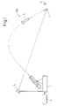
- eine Prinzipdarstellung des Verbringens einer Nutzlast mittels eines ballistischen Flugkörpers in ein Ziel,
- Fig. 2
- den Flugkörper aus Fig. 1 mit Teilen einer ersten Ausführung,
- Fig. 3
- eine Darstellung des aktivierten Bremssystems aus Fig. 1,
- Fig. 4
- Details des Bewegungssystems der ersten Ausführung,
- Fig. 5
- den Flugkörper aus Fig. 1 in einer weiteren Ausführung mit einem weiteren Bewegungssystem,
- Fig. 6 a) bis g)
- die Bewegungsabläufe des Bewegungssystems aus Fig. 5 zur Fortbewegung zum Ziel,
- Fig. 7
- eine Darstellung der Richtungsänderung des Flugkörpers aus Fig. 5 der Bewegung auf dem Boden.
- In Fig. 1 ist in einer Prinzipdarstellung das Verbringen einer Vorrichtung 100, eines vorzugsweise ballistischen Flugkörpers 3 (Gehäuses), hier ein Projektil, mit Hilfe einer Werfereinrichtung 1 (Werfer) dargestellt. Mit 2 ist eine Programmiereinrichtung gekennzeichnet, mit 5 eine Einrichtung insbesondere zur Bestimmung der Position des Aufsetz- bzw. Auftreffpunktes 4 (Auflageposition) des Projektils 3 auf dem Boden.
- Die Vorrichtung 100 bzw. das Projektil 3 (Fig. 2) besitzt (für alle Ausführungen geltend) vorzugsweise im vorderen Bereich, am Kopf, ein Bremssystem 7, hier einen Airbag. Zusätzlich oder alternativ kann ein Bremssystem, beispielsweise ein fallschirmartiger Airbag am hinteren Teil vorgesehen werden (nicht dargestellt). Das Projektil 3 beinhaltet des Weiteren ein Bewegungssystem 8, einen Rechner für die Ablauf- und Navigationssteuerung 9, ein Programmiermodul 10, ein Navigationssystem 11 sowie eine Einrichtung 12 zur Bestimmung der Richtung und eine Einrichtung 13 zur Bestimmung der zurückgelegten Wegstrecke. Bevorzugt wird das Navigationssystem 11 durch einen GPS- Empfänger 15 unterstützt. Die vorgenannten Einrichtungen 9 bis 12 sowie 15 sind funktional miteinander verschaltet. Eine zu verbringende Nutzlast 14 befindet sich im vorderen Bereich des Projektils 3.
- Sind die Koordinaten des Zielpunktes 6 nur als geodätische Koordinaten bekannt, ist es erforderlich, dass die geodätischen Koordinaten des Werfers 1 sowie eine Raumwinkelreferenz für die Abschussrichtung des Werfers 1 bekannt sind, um Azimut, Elevation sowie die Startgeschwindigkeit des Projektils 3 berechnen zu können.
- Ist der Zielpunkt 6 von der Position des Werfers 1 aus sichtbar, können Richtung und Entfernung zum Zielpunkt 6 mittels der Einrichtung 5, z.B. eines optischen Richtungs- und Entfernungsmessers, bestimmt werden. Näheres zu der Bestimmung kann der DE 101 47 837 A1 entnommen werden, auf die hiermit Bezug genommen wird. Mit diesem Vektor können Azimut und Elevation des Werfers 1 sowie die Startgeschwindigkeit des Projektils 3 berechnet werden.
- Dem Projektil 3 werden vor dem Abschuß die Zielkoordinaten sowie die Flugbahndaten einprogrammiert. Für diese Funktion zeichnen die Programmiereinrichtung 2 am Werfer 1 und ein Programmiermodul 10 im Projektil 3 verantwortlich. Danach verbringt der Werfer 1 das Projektil 3 ballistisch möglichst nahe an das Ziel 6. Auf der Flugbahn des Projektils 3 wird vorzugsweise bei ca. 5 m vor Auftreffen auf den Untergrund automatisch der Airbag 7 im Kopf des Projektils 3 aktiviert, um ein Eindringen des Projektils 3 in den Untergrund zu verhindern. Durch die kurze Distanz zum Boden wird erreicht, dass Abweichungen des Projektils 3 von der Sollflugbahn durch vom Airbag 7 verursachte Störungen der Aerodynamik minimiert werden.
- Nach dem Aufsetzen im Auftreffpunkt 4 besitzt das Projektil 3 einen Abstand zum Ziel 6, der sich durch außenballistische Einflüsse bestimmt. Der Vorgang des Aufsetzens auf den Boden führt zu weiteren Abweichungen von der einprogrammierten Position. Auch die Orientierung der Projektilachse zum Ziel 6 ist zufällig. Ist das Projektil 3 zur Ruhe gekommen, wird der Airbag 7 abgetrennt. Diese Aufgabe können kleine Sprengkörper am Airbag 7 (nicht näher dargestellt) übernehmen.
- Mittels der im Projektil 3 integrierten Navigationseinrichtung 11, bevorzugt nur mit dem GPS-Empfänger 15 realisiert, wird der Aufsetzpunkt 4 des Projektils 3 bestimmt. Das Projektil 3 startet nun sein Bewegungssystem 8, durch das es zum Ziel 6 geführt wird. Dabei bewegt sich das Projektil 3 zuerst in eine Richtung, die durch seine zufällige Ruheorientierung vorgegeben ist. Die GPS-gestützte Navigationseinrichtung 11 bestimmt Einzelpositionswerte auf der Wegstrecke. Aus diesen Punkten wird die Bewegungsrichtung des Projektils 3 im Erdkoordinatensystem ermittelt. Dieser Richtungswert dient dann zur Berechnung der Bewegungsrichtung B (Fig.4) des Projektils 3 zum Ziel 6. Mittels der GPS - Positionsdaten bewegt sich das Projektil 3 bis zur Position des Zieles 6. Die Auswertung der GPS-Daten und die Ansteuerung des Bewegungssystems 8 werden durch den Rechner 9 im Projektil 3 durchgeführt.
- Zusätzlich zum GPS-Empfänger 15 ist eine Einrichtung 12 zur Bestimmung der Richtung im Erdkoordinatensystem, vorzugsweise als Magnetsensor ausgeführt, im Projektil vorgesehen, der die Orientierung des Projektils zu magnetisch Nord und damit zu einem Erdkoordinatensystem bestimmt. Die Anfangsbewegung des Projektils.3 kann dann direkt in Richtung des Zielpunktes erfolgen. Dieser Richtungswert muß dann nicht erst aus der willkürlichen Anfangsbewegungsrichtung berechnet werden.
- Alternativ zur beschriebenen Navigation des Projektils 3 zum Ziel 6 kann die Position des Aufsetzpunktes 4 des Projektils durch die Einrichtung 5, die auf einer vermessenen Position im Gelände steht, vermessen werden. Die Messung kann in einer technischen Ausführung bevorzugt z.B. von der Werferposition aus, mit einem optischen Richtungs- und Entfernungsmessers kurz vor Aufsetzen des Projektils 3 auf den Boden erfolgen. Dabei bietet sich an, die Aktivierung des Airbags 7, der hierfür mit optischen Reflektoren 16 (Fig.3) versehen wird, für den Messvorgang zu nutzen. Der Aufsetzpunkt 4 selbst wird dann durch Extrapolation der Flugbahn berechnet. Diese berechnete Position wird dann in das Projektil 3 übertragen. Diese Übertragung kann per Funk erfolgen oder auch über die optronische Messstrecke selbst, wenn die Position des Projektils 3 aktiv optisch, z.B. über Laser, vermessen wird.
Das Navigationssystem 11 enthält dann bevorzugt nur einen Richtungssensor und einen Sensor zur Messung der zurückgelegten Wegstrecke. Auf ein GPS 15 kann dann verzichtet werden. - Für die Ausführung des Bewegungssystems 8 werden nunmehr zwei unterschiedliche Konzepte beschrieben:
- In einer ersten Ausführung des Bewegungssystems 8.1 bzw. -mechanismus bewirkt dieses eine Bewegung in Ausrichtung der Projektilachse. Kontrollierte Änderungen der Bewegungsrichtung B sind möglich.
- Hierzu ist das Projektil 3.1 in vorzugsweise drei zylinderförmige, koaxial angeordnete und miteinander verbundene Segmente 17, 18, 19 (Fig.4) unterteilt. Vorzugsweise im mittleren Segment 17 befinden sich je ein Antriebsmotor 20 für das vordere Segment 18 und das hintere Segment 19 (in Bewegungsrichtung betrachtet). Die Drehrichtung der Antriebe ist so, dass sich das vordere 18 und das hintere Segment 19 gleichsinnig drehen. Auf dem vorderen 18 und hinteren Segment 19 ist schraubenförmig ein Steg 21 aufgebracht. Die schraubenförmige Orientierung auf dem vorderen 18 und hinteren 19 Segment ist gleichsinnig. Die Steigung der Stege 21 ist gleich. Auf dem mittleren Segment 17 ist in umgekehrter Orientierung mit gleicher Steigung ein Steg 30 in ungefähr doppelter Länge zum Steg 21 des vorderen 18 bzw. hinteren Segments 19 aufgebracht. Dabei wird vorausgesetzt, dass das Gewicht des mittleren Segmentes 17 in etwa der Summe der Gewichte des vorderen 18 und des hinteren Segmentes 19 entspricht.
- Drehen nun die Motore 20 das vordere 18 und hintere Segment 19 gleichsinnig, führt das Gegenmoment zu einer Rotation des mittleren Segmentes 17 mit umgekehrtem Drehsinn. Der schraubenförmige Steg 21, 30 auf den Segmenten 17-19 führt durch die Reibung auf dem Untergrund zu einer Bewegung des Projektils 3 in seiner Längsachse, wenn die Reibung des vorderen 18 und hinteren Segmentes 19 auf dem Untergrund gleich ist und in der Summe der Reibung des mittleren Segmentes 17 entspricht. Durch Wahl der Drehrichtung kann sich das Projektil 3.1 vorwärts oder rückwärts bewegen.
- Um die Richtung des Projektils 3.1 zu seiner Längsachse verändern zu können, muß lediglich das Antriebsmoment des vorderen oder hinteren Antriebsmotors 20 verändert werden. Das führt zu einem Drehmoment, so dass sich die Orientierung der Projektilachse auf dem Untergrund verändert. Durch geeignete Ansteuerung der Motoren 20 (gegenläufige Drehrichtung) ist auch eine Kreisbewegung um den Mittelpunkt des Projektils 3.1 möglich.
- Damit ist eine kontrollierte Steuerung der Bewegung des Projektils 3.1 auf dem Untergrund möglich. Zusätzlich können auf diese Weise auch Unterschiede in der Reibung zwischen Untergrund und der aufliegenden Projektilfläche, die zu Kursabweichungen führen, kompensiert werden.
- In einer anderen Ausführung (Fig.5) besteht das Projektil 3.2 aus zwei ineinander liegenden zylinderförmigen und konzentrisch angeordneten Baugruppen, also einer außen liegenden Baugruppe 22 und einer innen liegenden Baugruppe 23. Die beiden Baugruppen 22, 23 können wie ein Teleskop auseinander- bzw. zusammengeschoben werden. Diese Funktion kann z.B. durch wenigstens einen Motor mit Zahnrad 24 in Kombination mit wenigstens einer Zahnstange 25 realisiert werden.
Die beiden röhrenförmigen Baugruppen 22, 23 sind jeweils am äußeren Ende mit einem Kopfstück 26 versehen, aus dem motorisch radial Stifte 27 ausgefahren und wieder eingefahren werden können. Im Kopfstück 26 sind bevorzugt sechs Stifte um 60 Grad zueinander versetzt angeordnet. Das Kopfstück 26 kann über einen Motor 28 kontrolliert gegenüber den Baugruppen 22 bzw. 23 verdreht werden. Die vorgenannten Bauteile definieren das Bewegungssystem 8.2 für dieses Projektil 3.2 . - Der Bewegungsablauf dieser Ausführung soll anhand der Fig. 6 a bis 6g näher betrachtet werden.
In Fig. 6a sind die beiden Baugruppen 22, 23 zusammengeschoben. Die beabsichtigte Bewegung erfolgt in der Orientierung der Projektilachse nach vorne (B). Das hintere Kopfstück 26 verschließt die äußere Baugruppe 22. Zuerst werden die Stifte 27 aus dem Kopfstück 26 der inneren Baugruppe 23 ausgefahren (Fig. 6b). Die Stifte 27 sind an ihren Enden so verbreitert, dass sie möglichst gut auf dem Untergrund haften. Dann wird die innere Baugruppe 23 motorisch 24 ausgeschoben, wobei die innere Baugruppe 23 durch die Haftung der Stifte 27 auf dem Untergrund in ihrer Position verharrt und die äußere Baugruppe 22 nach vorne geschoben wird (Fig. 6c). Nach Ausschieben der inneren Baugruppe 23 werden die Stifte 27 des hinteren Kopfstücks 26 wieder eingefahren (Fig. 6d) und die Stifte 27 aus dem vorderen Kopfstück 26 ausgefahren (Fig. 6e). Dann werden die beiden Baugruppen 22, 23 motorisch 24 wieder zusammengefahren (Fig. 6f) . Durch die Haftung der Stifte 27 des Kopfstücks 26 der äußeren Baugruppe 22 auf dem Untergrund wird die innere Baugruppe 22 in die verharrende äußere Baugruppe 23 gezogen. Damit hat sich das Projektil 3 in Richtung seiner Achse um etwa die Länge einer Baugruppe 22 /23 nach vorne geschoben. Nach Einfahren der Stifte 27 ist dann die Ausgangskonfiguration für den nächsten Zyklus gegeben (Fig. 6g). - Um eine Richtungsänderung zu bewirken, wird das Kopfstück 26 einer Baugruppe 22, 23 dann gedreht, wenn die Stifte 27 ausgeschoben sind. Das Kopfstück 26 wird über den zugehörigen Kopfmotor 28 soweit gedreht, bis die gewünschte Änderung der Richtung um den Winkel α erreicht ist (Fig. 7). Werden beide Kopfstücke 26 über Motore 28 an der jeweiligen Baugruppen 22, 23 bewegt, kann das Projektil 3.1 bei gegenläufiger Bewegungsrichtung der Motore 28 um die Mittelachse herum jede gewünschte Orientierung einnehmen.
- Die hier beschriebenen Bewegungssysteme 8.1 , 8.2 sind nur beispielgebend. Es versteht sich, dass diese nicht einschränkend zu sehen sind, sondern auch weitere im Rahmen der Erfindung liegende Bewegungssysteme umfasst sind, mit deren Hilfe ein Wurfkörper, Projektil etc. von einer Position zu einer anderen selbst kriechend verbracht werden kann.
Claims (12)
- Vorrichtung (100), enthaltend eine Nutzlast (14), die insbesondere zum Auslösen von offen oder verdeckt verlegten Minen, Sprengkörpern oder dergleichen dient, aufweisend einen als Wurf -oder Flugkörper ausgebildeten Körper (3, 3.1, 3.2), in dem zumindest einen Rechner (9) für die Ablauf- und Navigationssteuerung, sowie damit elektrisch verbunden ein Programmiermodul (10) und ein Navigationssystem (11) enthalten sind, dadurch gekennzeichnet, dass ein Bewegungssystem (8, 8.1, 8.2) eingebunden ist, welches den Körper (3) mit der Nutzlast (14) nach dem Aufsetzen auf einen Aufsetzpunkt (4) direkt auf das Ziel (6) führt.
- Vorrichtung nach Anspruch 1, dadurch gekennzeichnet, dass eine Einrichtung (12) zur Bestimmung der Richtung und eine Einrichtung (13) zur Bestimmung der zurückgelegten Wegstrecke im Körper (3) eingebunden ist.
- Vorrichtung nach Anspruch 1 oder 2, dadurch gekennzeichnet, dass ein Bremssystem (7) am Körper (3) vorgesehen ist.
- Vorrichtung nach Anspruch 3, dadurch gekennzeichnet, dass das Bremssystem (7) ein Airbag ist.
- Vorrichtung nach einem der Ansprüche 1 bis 4, dadurch gekennzeichnet, dass der Körper (3.1) in zylinderförmige, koaxial angeordnete und miteinander verbundene Segmente (17, 18, 19) unterteilt ist.
- Vorrichtung nach Anspruch 5, dadurch gekennzeichnet, dass im mittleren Segment (17) sich je ein Antriebsmotor (20) für das vordere Segment (18) und das hintere Segment (19) befindet.
- Vorrichtung nach Anspruch 6, dadurch gekennzeichnet, dass auf dem vorderen Segment (18) und dem hinteren Segment (19) schraubenförmig ein Steg (21) aufgebracht ist, dessen schraubenförmige Orientierung auf dem vorderen Segment (18) und dem hinteren Segment (19) gleichsinnig ist.
- Vorrichtung nach Anspruch 7, dadurch gekennzeichnet, dass die Steigung der Stege (21) ist gleich.
- Vorrichtung nach einem der Ansprüche 5 bis 8, dadurch gekennzeichnet, dass auf dem mittleren Segment (17) ein Steg (30) in umgekehrter Orientierung mit gleicher Steigung und in ungefähr doppelter Länge zum Steg (21) des vorderen bzw. hinteren Segments (18,19) aufgebracht ist.
- Vorrichtung nach einem der Ansprüche 1 bis 4, dadurch gekennzeichnet, dass der Körper (3.2) aus zwei ineinander liegenden zylinderförmigen und konzentrisch angeordneten Baugruppen (22, 23), einer außenliegenden Baugruppe (22) und einer innen liegenden Baugruppe (23) gebildet wird, die wie ein Teleskop auseinander- bzw. zusammengeschoben werden können, wobei die Baugruppen (22, 23) jeweils am äußeren Ende jeweils mit einem Kopfstück (26) versehen sind, aus denen radiale Stifte (27) ausgefahren und wieder eingefahren werden können.
- Vorrichtung nach Anspruch 10, dadurch gekennzeichnet, dass im Kopfstück (26) jeweils sechs Stifte (27) und diese zueinander um 60 Grad versetzt angeordnet sind.
- Vorrichtung nach einem der Ansprüche 10 oder 11, dadurch gekennzeichnet, dass das Kopfstück (26) über einen Motor (28) kontrolliert gegenüber den Baugruppen (22, 23) verdreht werden kann.
Applications Claiming Priority (1)
| Application Number | Priority Date | Filing Date | Title |
|---|---|---|---|
| DE102004046571A DE102004046571A1 (de) | 2004-09-24 | 2004-09-24 | Vorrichtung zum Verbringen einer Nutzlast, insbesondere zur Neutralisierung von Minen oder dergleichen |
Publications (2)
| Publication Number | Publication Date |
|---|---|
| EP1640686A1 true EP1640686A1 (de) | 2006-03-29 |
| EP1640686B1 EP1640686B1 (de) | 2008-02-13 |
Family
ID=35262073
Family Applications (1)
| Application Number | Title | Priority Date | Filing Date |
|---|---|---|---|
| EP05015718A Expired - Lifetime EP1640686B1 (de) | 2004-09-24 | 2005-07-20 | Vorrichtung zum Verbringen einer Nutzlast, insbesondere zur Neutralisierung von Minen oder dergleichen |
Country Status (5)
| Country | Link |
|---|---|
| US (1) | US7493843B2 (de) |
| EP (1) | EP1640686B1 (de) |
| AT (1) | ATE386249T1 (de) |
| CA (1) | CA2520470A1 (de) |
| DE (2) | DE102004046571A1 (de) |
Cited By (1)
| Publication number | Priority date | Publication date | Assignee | Title |
|---|---|---|---|---|
| WO2010028759A1 (de) * | 2008-09-09 | 2010-03-18 | Rheinmetall Waffe Munition Gmbh | Vorrichtung und verfahren zur abwehr von sich einem schiff under oder auf dem wasser näherden objekten |
Families Citing this family (11)
| Publication number | Priority date | Publication date | Assignee | Title |
|---|---|---|---|---|
| DE102007018137B3 (de) * | 2007-04-16 | 2008-10-30 | Rheinmetall Landsysteme Gmbh | Neutralisierungsverfahren für Sprengkörper und Vorrichtung zur Durchführung des Verfahrens |
| US8403267B2 (en) * | 2010-11-29 | 2013-03-26 | Raytheon Company | Ejection system and a method for ejecting a payload from a payload delivery vehicle |
| US8904937B2 (en) | 2012-04-13 | 2014-12-09 | C-2 Innovations Inc. | Line charge |
| US8939056B1 (en) * | 2012-04-20 | 2015-01-27 | Barron Associates, Inc. | Systems, devices, and/or methods for managing targeted payload descent |
| GB2517173A (en) * | 2013-08-13 | 2015-02-18 | Saab Seaeye Ltd | Charge deployment system for ordnance neutralisation |
| US9561842B1 (en) | 2013-09-17 | 2017-02-07 | The United States Of America As Represented By The Secretary Of The Navy | Remote control mine neutralization delivery system |
| WO2016035066A1 (en) * | 2014-09-02 | 2016-03-10 | HAYIK, Isaak | Self propelling subterranean vehicle |
| CN107763367B (zh) * | 2017-11-16 | 2023-08-01 | 北华大学 | 螺旋驱动离心式机械自适应调速装置 |
| US11498652B2 (en) * | 2019-04-25 | 2022-11-15 | United States Of America As Represented By The Secretary Of The Navy | Unmanned undersand vehicle |
| CN113650816B (zh) * | 2021-08-20 | 2023-06-30 | 北京精密机电控制设备研究所 | 一种多级伸缩腿嵌套导向与步进装置及方法 |
| WO2025199500A1 (en) * | 2024-03-22 | 2025-09-25 | Insights International Holdings, Llc | Projectile delivery system for supplies with impact attenuation |
Citations (9)
| Publication number | Priority date | Publication date | Assignee | Title |
|---|---|---|---|---|
| US1388545A (en) * | 1917-12-03 | 1921-08-23 | William J Bohan | Self-intrenching subsurface land-torpedo |
| US3921739A (en) * | 1974-09-30 | 1975-11-25 | Farmer Foundation Company | Walking platform for drilling rigs and other heavy machinery |
| US4505441A (en) * | 1983-06-20 | 1985-03-19 | Grumman Aerospace Corporation | Terrain-following transient surface contact vehicle |
| US4505442A (en) * | 1983-06-20 | 1985-03-19 | Grumman Aerospace Corporation | Transient surface contact vehicle |
| DE3535337A1 (de) * | 1985-10-03 | 1987-04-09 | Messerschmitt Boelkow Blohm | Waffentraeger |
| DE19619135C2 (de) | 1996-05-11 | 1999-03-25 | Rheinmetall Ind Ag | Unbemanntes gepanzertes Minenräumfahrzeug |
| US6237875B1 (en) * | 1998-08-18 | 2001-05-29 | Daimlerchrysler Ag | Airbag payload landing system for damping landing impact forces on a flying payload |
| DE10147837A1 (de) | 2001-09-27 | 2003-04-24 | Rheinmetall Landsysteme Gmbh | Wurfsystem für einen Gefechtskopf mit einer Richtvorrichtung zur Neutralisierung von Minen |
| DE10215200A1 (de) | 2002-04-05 | 2003-10-16 | Klaus Schulze | Gaswächter zum Überwachen der Gasdichtheit von Gasanlagen und automatischem Absperren, wenn eine vorgegebene Undichtheit überschritten wird |
Family Cites Families (22)
| Publication number | Priority date | Publication date | Assignee | Title |
|---|---|---|---|---|
| US1303764A (en) * | 1919-05-13 | Armored war apparatus | ||
| US2480927A (en) * | 1944-03-16 | 1949-09-06 | Raymonde Briggs Hopkins | Aerial torpedo |
| US2973172A (en) * | 1957-09-16 | 1961-02-28 | Northrop Corp | Radial cell decelerator |
| US3088403A (en) * | 1959-05-26 | 1963-05-07 | James T Bartling | Rocket assisted torpedo |
| US5012717A (en) * | 1964-09-29 | 1991-05-07 | The United States Of America As Represented By The Secretary Of The Navy | Air-to-subsurface missile system |
| FR2112582A6 (de) * | 1970-05-29 | 1972-06-23 | Thomson Csf | |
| US4451992A (en) | 1982-09-30 | 1984-06-05 | Spring - Mornne, Inc. | Method and apparatus for positioning a shaft aligning sensing structure on a shaft |
| US4493240A (en) * | 1983-02-01 | 1985-01-15 | Stresau Laboratory, Inc. | Parachute line cutting device |
| CA1202606A (en) * | 1984-02-15 | 1986-04-01 | Michel C. St-Onge | Tension link for parachute/payload separation |
| US4860968A (en) * | 1988-04-15 | 1989-08-29 | The Boeing Company | Communication link between moving bodies |
| SE461611B (sv) * | 1988-07-12 | 1990-03-05 | S A Marine Ab | Saett och anordning foer upptaeckt och bekaempning av undervattensfarkoster fraan en luftfarkost |
| DE4431842C2 (de) * | 1994-09-07 | 1998-10-01 | Gmd Gmbh | Elektronisch steuerbare Vorrichtung |
| EP0794405B1 (de) * | 1996-03-08 | 2001-09-05 | Diehl Stiftung & Co. | Verfahren und Einrichtung zum Verbringen einer grosskalibrigen Nutzlast über ein Einsatzgelände |
| US5932833A (en) * | 1997-03-03 | 1999-08-03 | The United States Of America As Represented By The Secretary Of The Army | Fly over homing guidance for fire and forget missile systems |
| US6293202B1 (en) * | 1998-08-17 | 2001-09-25 | The United States Of America As Represented By The Secretary Of The Navy | Precision, airborne deployed, GPS guided standoff torpedo |
| US6502657B2 (en) * | 2000-09-22 | 2003-01-07 | The Charles Stark Draper Laboratory, Inc. | Transformable vehicle |
| US6626078B2 (en) * | 2000-11-30 | 2003-09-30 | Lockheed Martin Corporation | Apparatus for detecting, identifying, and validating the existence of buried objects |
| US6809520B1 (en) * | 2001-12-04 | 2004-10-26 | The Johns Hopkins University | Compact, autonomous robotic detection and identification sensor system of unexploded ordnance site remediation |
| DE10215220B4 (de) * | 2002-04-06 | 2006-09-07 | Rheinmetall Landsysteme Gmbh | Minensuch- und Räumsystem für Landminen |
| DE20205547U1 (de) * | 2002-04-10 | 2002-08-14 | Györy, Kalman, 21376 Gödenstorf | Landmienenentsorgungsroboter |
| US6738314B1 (en) * | 2003-01-31 | 2004-05-18 | L3 Communications Corporation | Autonomous mine neutralization system |
| US6974356B2 (en) * | 2003-05-19 | 2005-12-13 | Nekton Research Llc | Amphibious robot devices and related methods |
-
2004
- 2004-09-24 DE DE102004046571A patent/DE102004046571A1/de not_active Withdrawn
-
2005
- 2005-07-20 AT AT05015718T patent/ATE386249T1/de not_active IP Right Cessation
- 2005-07-20 EP EP05015718A patent/EP1640686B1/de not_active Expired - Lifetime
- 2005-07-20 DE DE502005002808T patent/DE502005002808D1/de not_active Expired - Lifetime
- 2005-09-22 CA CA002520470A patent/CA2520470A1/en not_active Abandoned
- 2005-09-26 US US11/235,267 patent/US7493843B2/en not_active Expired - Fee Related
Patent Citations (9)
| Publication number | Priority date | Publication date | Assignee | Title |
|---|---|---|---|---|
| US1388545A (en) * | 1917-12-03 | 1921-08-23 | William J Bohan | Self-intrenching subsurface land-torpedo |
| US3921739A (en) * | 1974-09-30 | 1975-11-25 | Farmer Foundation Company | Walking platform for drilling rigs and other heavy machinery |
| US4505441A (en) * | 1983-06-20 | 1985-03-19 | Grumman Aerospace Corporation | Terrain-following transient surface contact vehicle |
| US4505442A (en) * | 1983-06-20 | 1985-03-19 | Grumman Aerospace Corporation | Transient surface contact vehicle |
| DE3535337A1 (de) * | 1985-10-03 | 1987-04-09 | Messerschmitt Boelkow Blohm | Waffentraeger |
| DE19619135C2 (de) | 1996-05-11 | 1999-03-25 | Rheinmetall Ind Ag | Unbemanntes gepanzertes Minenräumfahrzeug |
| US6237875B1 (en) * | 1998-08-18 | 2001-05-29 | Daimlerchrysler Ag | Airbag payload landing system for damping landing impact forces on a flying payload |
| DE10147837A1 (de) | 2001-09-27 | 2003-04-24 | Rheinmetall Landsysteme Gmbh | Wurfsystem für einen Gefechtskopf mit einer Richtvorrichtung zur Neutralisierung von Minen |
| DE10215200A1 (de) | 2002-04-05 | 2003-10-16 | Klaus Schulze | Gaswächter zum Überwachen der Gasdichtheit von Gasanlagen und automatischem Absperren, wenn eine vorgegebene Undichtheit überschritten wird |
Cited By (1)
| Publication number | Priority date | Publication date | Assignee | Title |
|---|---|---|---|---|
| WO2010028759A1 (de) * | 2008-09-09 | 2010-03-18 | Rheinmetall Waffe Munition Gmbh | Vorrichtung und verfahren zur abwehr von sich einem schiff under oder auf dem wasser näherden objekten |
Also Published As
| Publication number | Publication date |
|---|---|
| DE102004046571A1 (de) | 2006-04-06 |
| EP1640686B1 (de) | 2008-02-13 |
| US20080148926A1 (en) | 2008-06-26 |
| DE502005002808D1 (de) | 2008-03-27 |
| CA2520470A1 (en) | 2006-03-24 |
| ATE386249T1 (de) | 2008-03-15 |
| US7493843B2 (en) | 2009-02-24 |
Similar Documents
| Publication | Publication Date | Title |
|---|---|---|
| EP0636852B1 (de) | Mittels Canard-Rudern gesteuerte Artillerie-Rakete | |
| EP1640686B1 (de) | Vorrichtung zum Verbringen einer Nutzlast, insbesondere zur Neutralisierung von Minen oder dergleichen | |
| DE69607944T2 (de) | Verfahren und vorrichtung zur bahnkorrektur eines ballistischen geschosses mittels radialen schüben | |
| EP2071270B1 (de) | Taumelzünder | |
| DE2336040A1 (de) | Abwehrsystem, insbesondere fuer die panzerbekaempfung | |
| EP2594891B1 (de) | Verfahren zum Abwehren einer anfliegenden ballistischen Rakete und Abfangsystem | |
| DE2538665A1 (de) | Verfahren und einrichtung zum streuwurf von bomben | |
| DE69410376T2 (de) | Waffensystem für die verteidigung eines gebietes | |
| DE4306913A1 (de) | Feuerleiteinrichtung für, insbesondere mobile, Flugabwehrsysteme | |
| DE3522154C2 (de) | ||
| DE102012002043C5 (de) | Waffenbasierte Schutzeinrichtung für Fahrzeuge | |
| DE3543769A1 (de) | Mine zur abwehr von bewegten objekten | |
| DE3013405A1 (de) | Verfahren zum vermeiden des nachrichtens von abschussgeraeten fuer ballistische flugkoerper | |
| EP0049778B1 (de) | Verfahren zum Verteilen von Gefechtskörpern | |
| DE102014010109A1 (de) | Flugkörper | |
| EP0384965A2 (de) | Flügelstabilisierter Submunitionskörper | |
| EP1298409A1 (de) | Wurfsystem für einen Gefechtskopf mit einer Richtvorrichtung zur Neutralisierung von Minen | |
| DE19845611A1 (de) | Verfahren zur Flugbahnkorrektur von Flugkörpern | |
| EP0492299A2 (de) | Mine mit einer Verlegeeinrichtung für eine Sensorleitung | |
| DE19540252C2 (de) | Verfahren zum Führen von Submunition in ein Ziel und Träger hierfür | |
| DE102014007456B3 (de) | Modulares Lenkflugkörpersystem | |
| EP3156757B1 (de) | Waffensystem und verfahren zum betreiben eines waffensystems | |
| DE3529897A1 (de) | Flugkoerper zur bekaempfung von zielen beim ueberfliegen | |
| EP1688702A1 (de) | Einrichtung zur Steigerung der Präzision heckflügelstabilisierter Munition | |
| DE3535337A1 (de) | Waffentraeger |
Legal Events
| Date | Code | Title | Description |
|---|---|---|---|
| PUAI | Public reference made under article 153(3) epc to a published international application that has entered the european phase |
Free format text: ORIGINAL CODE: 0009012 |
|
| 17P | Request for examination filed |
Effective date: 20051203 |
|
| AK | Designated contracting states |
Kind code of ref document: A1 Designated state(s): AT BE BG CH CY CZ DE DK EE ES FI FR GB GR HU IE IS IT LI LT LU LV MC NL PL PT RO SE SI SK TR |
|
| AX | Request for extension of the european patent |
Extension state: AL BA HR MK YU |
|
| AKX | Designation fees paid |
Designated state(s): AT BE BG CH CY CZ DE DK EE ES FI FR GB GR HU IE IS IT LI LT LU LV MC NL PL PT RO SE SI SK TR |
|
| 17Q | First examination report despatched |
Effective date: 20060509 |
|
| GRAP | Despatch of communication of intention to grant a patent |
Free format text: ORIGINAL CODE: EPIDOSNIGR1 |
|
| GRAS | Grant fee paid |
Free format text: ORIGINAL CODE: EPIDOSNIGR3 |
|
| GRAA | (expected) grant |
Free format text: ORIGINAL CODE: 0009210 |
|
| AK | Designated contracting states |
Kind code of ref document: B1 Designated state(s): AT BE BG CH CY CZ DE DK EE ES FI FR GB GR HU IE IS IT LI LT LU LV MC NL PL PT RO SE SI SK TR |
|
| REG | Reference to a national code |
Ref country code: GB Ref legal event code: FG4D Free format text: NOT ENGLISH |
|
| REG | Reference to a national code |
Ref country code: CH Ref legal event code: EP |
|
| REG | Reference to a national code |
Ref country code: IE Ref legal event code: FG4D Free format text: LANGUAGE OF EP DOCUMENT: GERMAN |
|
| REF | Corresponds to: |
Ref document number: 502005002808 Country of ref document: DE Date of ref document: 20080327 Kind code of ref document: P |
|
| GBT | Gb: translation of ep patent filed (gb section 77(6)(a)/1977) |
Effective date: 20080410 |
|
| PG25 | Lapsed in a contracting state [announced via postgrant information from national office to epo] |
Ref country code: IS Free format text: LAPSE BECAUSE OF FAILURE TO SUBMIT A TRANSLATION OF THE DESCRIPTION OR TO PAY THE FEE WITHIN THE PRESCRIBED TIME-LIMIT Effective date: 20080613 Ref country code: ES Free format text: LAPSE BECAUSE OF FAILURE TO SUBMIT A TRANSLATION OF THE DESCRIPTION OR TO PAY THE FEE WITHIN THE PRESCRIBED TIME-LIMIT Effective date: 20080524 Ref country code: FI Free format text: LAPSE BECAUSE OF FAILURE TO SUBMIT A TRANSLATION OF THE DESCRIPTION OR TO PAY THE FEE WITHIN THE PRESCRIBED TIME-LIMIT Effective date: 20080213 |
|
| NLV1 | Nl: lapsed or annulled due to failure to fulfill the requirements of art. 29p and 29m of the patents act | ||
| ET | Fr: translation filed | ||
| PG25 | Lapsed in a contracting state [announced via postgrant information from national office to epo] |
Ref country code: PL Free format text: LAPSE BECAUSE OF FAILURE TO SUBMIT A TRANSLATION OF THE DESCRIPTION OR TO PAY THE FEE WITHIN THE PRESCRIBED TIME-LIMIT Effective date: 20080213 Ref country code: SI Free format text: LAPSE BECAUSE OF FAILURE TO SUBMIT A TRANSLATION OF THE DESCRIPTION OR TO PAY THE FEE WITHIN THE PRESCRIBED TIME-LIMIT Effective date: 20080213 Ref country code: LV Free format text: LAPSE BECAUSE OF FAILURE TO SUBMIT A TRANSLATION OF THE DESCRIPTION OR TO PAY THE FEE WITHIN THE PRESCRIBED TIME-LIMIT Effective date: 20080213 |
|
| REG | Reference to a national code |
Ref country code: IE Ref legal event code: FD4D |
|
| PG25 | Lapsed in a contracting state [announced via postgrant information from national office to epo] |
Ref country code: SK Free format text: LAPSE BECAUSE OF FAILURE TO SUBMIT A TRANSLATION OF THE DESCRIPTION OR TO PAY THE FEE WITHIN THE PRESCRIBED TIME-LIMIT Effective date: 20080213 Ref country code: IE Free format text: LAPSE BECAUSE OF FAILURE TO SUBMIT A TRANSLATION OF THE DESCRIPTION OR TO PAY THE FEE WITHIN THE PRESCRIBED TIME-LIMIT Effective date: 20080213 Ref country code: DK Free format text: LAPSE BECAUSE OF FAILURE TO SUBMIT A TRANSLATION OF THE DESCRIPTION OR TO PAY THE FEE WITHIN THE PRESCRIBED TIME-LIMIT Effective date: 20080213 Ref country code: CZ Free format text: LAPSE BECAUSE OF FAILURE TO SUBMIT A TRANSLATION OF THE DESCRIPTION OR TO PAY THE FEE WITHIN THE PRESCRIBED TIME-LIMIT Effective date: 20080213 Ref country code: SE Free format text: LAPSE BECAUSE OF FAILURE TO SUBMIT A TRANSLATION OF THE DESCRIPTION OR TO PAY THE FEE WITHIN THE PRESCRIBED TIME-LIMIT Effective date: 20080513 Ref country code: PT Free format text: LAPSE BECAUSE OF FAILURE TO SUBMIT A TRANSLATION OF THE DESCRIPTION OR TO PAY THE FEE WITHIN THE PRESCRIBED TIME-LIMIT Effective date: 20080714 Ref country code: NL Free format text: LAPSE BECAUSE OF FAILURE TO SUBMIT A TRANSLATION OF THE DESCRIPTION OR TO PAY THE FEE WITHIN THE PRESCRIBED TIME-LIMIT Effective date: 20080213 |
|
| PG25 | Lapsed in a contracting state [announced via postgrant information from national office to epo] |
Ref country code: RO Free format text: LAPSE BECAUSE OF FAILURE TO SUBMIT A TRANSLATION OF THE DESCRIPTION OR TO PAY THE FEE WITHIN THE PRESCRIBED TIME-LIMIT Effective date: 20080213 |
|
| PLBE | No opposition filed within time limit |
Free format text: ORIGINAL CODE: 0009261 |
|
| STAA | Information on the status of an ep patent application or granted ep patent |
Free format text: STATUS: NO OPPOSITION FILED WITHIN TIME LIMIT |
|
| 26N | No opposition filed |
Effective date: 20081114 |
|
| PG25 | Lapsed in a contracting state [announced via postgrant information from national office to epo] |
Ref country code: LT Free format text: LAPSE BECAUSE OF FAILURE TO SUBMIT A TRANSLATION OF THE DESCRIPTION OR TO PAY THE FEE WITHIN THE PRESCRIBED TIME-LIMIT Effective date: 20080213 |
|
| PG25 | Lapsed in a contracting state [announced via postgrant information from national office to epo] |
Ref country code: MC Free format text: LAPSE BECAUSE OF NON-PAYMENT OF DUE FEES Effective date: 20080731 |
|
| PG25 | Lapsed in a contracting state [announced via postgrant information from national office to epo] |
Ref country code: EE Free format text: LAPSE BECAUSE OF FAILURE TO SUBMIT A TRANSLATION OF THE DESCRIPTION OR TO PAY THE FEE WITHIN THE PRESCRIBED TIME-LIMIT Effective date: 20080213 Ref country code: BG Free format text: LAPSE BECAUSE OF FAILURE TO SUBMIT A TRANSLATION OF THE DESCRIPTION OR TO PAY THE FEE WITHIN THE PRESCRIBED TIME-LIMIT Effective date: 20080513 |
|
| PG25 | Lapsed in a contracting state [announced via postgrant information from national office to epo] |
Ref country code: CY Free format text: LAPSE BECAUSE OF FAILURE TO SUBMIT A TRANSLATION OF THE DESCRIPTION OR TO PAY THE FEE WITHIN THE PRESCRIBED TIME-LIMIT Effective date: 20080213 |
|
| PG25 | Lapsed in a contracting state [announced via postgrant information from national office to epo] |
Ref country code: IT Free format text: LAPSE BECAUSE OF FAILURE TO SUBMIT A TRANSLATION OF THE DESCRIPTION OR TO PAY THE FEE WITHIN THE PRESCRIBED TIME-LIMIT Effective date: 20080213 |
|
| PG25 | Lapsed in a contracting state [announced via postgrant information from national office to epo] |
Ref country code: AT Free format text: LAPSE BECAUSE OF NON-PAYMENT OF DUE FEES Effective date: 20080720 |
|
| REG | Reference to a national code |
Ref country code: CH Ref legal event code: PL |
|
| PG25 | Lapsed in a contracting state [announced via postgrant information from national office to epo] |
Ref country code: LI Free format text: LAPSE BECAUSE OF NON-PAYMENT OF DUE FEES Effective date: 20090731 Ref country code: CH Free format text: LAPSE BECAUSE OF NON-PAYMENT OF DUE FEES Effective date: 20090731 |
|
| PG25 | Lapsed in a contracting state [announced via postgrant information from national office to epo] |
Ref country code: LU Free format text: LAPSE BECAUSE OF NON-PAYMENT OF DUE FEES Effective date: 20080720 Ref country code: HU Free format text: LAPSE BECAUSE OF FAILURE TO SUBMIT A TRANSLATION OF THE DESCRIPTION OR TO PAY THE FEE WITHIN THE PRESCRIBED TIME-LIMIT Effective date: 20080814 Ref country code: BE Free format text: LAPSE BECAUSE OF NON-PAYMENT OF DUE FEES Effective date: 20080731 |
|
| PG25 | Lapsed in a contracting state [announced via postgrant information from national office to epo] |
Ref country code: TR Free format text: LAPSE BECAUSE OF FAILURE TO SUBMIT A TRANSLATION OF THE DESCRIPTION OR TO PAY THE FEE WITHIN THE PRESCRIBED TIME-LIMIT Effective date: 20080213 |
|
| PG25 | Lapsed in a contracting state [announced via postgrant information from national office to epo] |
Ref country code: GR Free format text: LAPSE BECAUSE OF FAILURE TO SUBMIT A TRANSLATION OF THE DESCRIPTION OR TO PAY THE FEE WITHIN THE PRESCRIBED TIME-LIMIT Effective date: 20080514 |
|
| REG | Reference to a national code |
Ref country code: FR Ref legal event code: PLFP Year of fee payment: 12 |
|
| PGFP | Annual fee paid to national office [announced via postgrant information from national office to epo] |
Ref country code: GB Payment date: 20160721 Year of fee payment: 12 Ref country code: DE Payment date: 20160722 Year of fee payment: 12 |
|
| PGFP | Annual fee paid to national office [announced via postgrant information from national office to epo] |
Ref country code: FR Payment date: 20160721 Year of fee payment: 12 |
|
| REG | Reference to a national code |
Ref country code: DE Ref legal event code: R119 Ref document number: 502005002808 Country of ref document: DE |
|
| GBPC | Gb: european patent ceased through non-payment of renewal fee |
Effective date: 20170720 |
|
| REG | Reference to a national code |
Ref country code: FR Ref legal event code: ST Effective date: 20180330 |
|
| PG25 | Lapsed in a contracting state [announced via postgrant information from national office to epo] |
Ref country code: DE Free format text: LAPSE BECAUSE OF NON-PAYMENT OF DUE FEES Effective date: 20180201 Ref country code: GB Free format text: LAPSE BECAUSE OF NON-PAYMENT OF DUE FEES Effective date: 20170720 |
|
| PG25 | Lapsed in a contracting state [announced via postgrant information from national office to epo] |
Ref country code: FR Free format text: LAPSE BECAUSE OF NON-PAYMENT OF DUE FEES Effective date: 20170731 |