EP1640581B1 - Viertaktmotor - Google Patents
Viertaktmotor Download PDFInfo
- Publication number
- EP1640581B1 EP1640581B1 EP04745634A EP04745634A EP1640581B1 EP 1640581 B1 EP1640581 B1 EP 1640581B1 EP 04745634 A EP04745634 A EP 04745634A EP 04745634 A EP04745634 A EP 04745634A EP 1640581 B1 EP1640581 B1 EP 1640581B1
- Authority
- EP
- European Patent Office
- Prior art keywords
- catalyst
- catalysts
- secondary air
- exhaust pipe
- exhaust
- Prior art date
- Legal status (The legal status is an assumption and is not a legal conclusion. Google has not performed a legal analysis and makes no representation as to the accuracy of the status listed.)
- Expired - Lifetime
Links
Images

Classifications
-
- F—MECHANICAL ENGINEERING; LIGHTING; HEATING; WEAPONS; BLASTING
- F01—MACHINES OR ENGINES IN GENERAL; ENGINE PLANTS IN GENERAL; STEAM ENGINES
- F01N—GAS-FLOW SILENCERS OR EXHAUST APPARATUS FOR MACHINES OR ENGINES IN GENERAL; GAS-FLOW SILENCERS OR EXHAUST APPARATUS FOR INTERNAL-COMBUSTION ENGINES
- F01N3/00—Exhaust or silencing apparatus having means for purifying, rendering innocuous, or otherwise treating exhaust
- F01N3/08—Exhaust or silencing apparatus having means for purifying, rendering innocuous, or otherwise treating exhaust for rendering innocuous
- F01N3/10—Exhaust or silencing apparatus having means for purifying, rendering innocuous, or otherwise treating exhaust for rendering innocuous by thermal or catalytic conversion of noxious components of exhaust
- F01N3/24—Exhaust or silencing apparatus having means for purifying, rendering innocuous, or otherwise treating exhaust for rendering innocuous by thermal or catalytic conversion of noxious components of exhaust characterised by constructional aspects of converting apparatus
- F01N3/30—Arrangements for supply of additional air
-
- F—MECHANICAL ENGINEERING; LIGHTING; HEATING; WEAPONS; BLASTING
- F01—MACHINES OR ENGINES IN GENERAL; ENGINE PLANTS IN GENERAL; STEAM ENGINES
- F01N—GAS-FLOW SILENCERS OR EXHAUST APPARATUS FOR MACHINES OR ENGINES IN GENERAL; GAS-FLOW SILENCERS OR EXHAUST APPARATUS FOR INTERNAL-COMBUSTION ENGINES
- F01N13/00—Exhaust or silencing apparatus characterised by constructional features
- F01N13/009—Exhaust or silencing apparatus characterised by constructional features having two or more separate purifying devices arranged in series
-
- F—MECHANICAL ENGINEERING; LIGHTING; HEATING; WEAPONS; BLASTING
- F01—MACHINES OR ENGINES IN GENERAL; ENGINE PLANTS IN GENERAL; STEAM ENGINES
- F01N—GAS-FLOW SILENCERS OR EXHAUST APPARATUS FOR MACHINES OR ENGINES IN GENERAL; GAS-FLOW SILENCERS OR EXHAUST APPARATUS FOR INTERNAL-COMBUSTION ENGINES
- F01N3/00—Exhaust or silencing apparatus having means for purifying, rendering innocuous, or otherwise treating exhaust
- F01N3/08—Exhaust or silencing apparatus having means for purifying, rendering innocuous, or otherwise treating exhaust for rendering innocuous
- F01N3/10—Exhaust or silencing apparatus having means for purifying, rendering innocuous, or otherwise treating exhaust for rendering innocuous by thermal or catalytic conversion of noxious components of exhaust
- F01N3/18—Exhaust or silencing apparatus having means for purifying, rendering innocuous, or otherwise treating exhaust for rendering innocuous by thermal or catalytic conversion of noxious components of exhaust characterised by methods of operation; Control
- F01N3/22—Control of additional air supply only, e.g. using by-passes or variable air pump drives
-
- F—MECHANICAL ENGINEERING; LIGHTING; HEATING; WEAPONS; BLASTING
- F01—MACHINES OR ENGINES IN GENERAL; ENGINE PLANTS IN GENERAL; STEAM ENGINES
- F01N—GAS-FLOW SILENCERS OR EXHAUST APPARATUS FOR MACHINES OR ENGINES IN GENERAL; GAS-FLOW SILENCERS OR EXHAUST APPARATUS FOR INTERNAL-COMBUSTION ENGINES
- F01N2270/00—Mixing air with exhaust gases
-
- F—MECHANICAL ENGINEERING; LIGHTING; HEATING; WEAPONS; BLASTING
- F02—COMBUSTION ENGINES; HOT-GAS OR COMBUSTION-PRODUCT ENGINE PLANTS
- F02B—INTERNAL-COMBUSTION PISTON ENGINES; COMBUSTION ENGINES IN GENERAL
- F02B75/00—Other engines
- F02B75/02—Engines characterised by their cycles, e.g. six-stroke
- F02B2075/022—Engines characterised by their cycles, e.g. six-stroke having less than six strokes per cycle
- F02B2075/027—Engines characterised by their cycles, e.g. six-stroke having less than six strokes per cycle four
-
- Y—GENERAL TAGGING OF NEW TECHNOLOGICAL DEVELOPMENTS; GENERAL TAGGING OF CROSS-SECTIONAL TECHNOLOGIES SPANNING OVER SEVERAL SECTIONS OF THE IPC; TECHNICAL SUBJECTS COVERED BY FORMER USPC CROSS-REFERENCE ART COLLECTIONS [XRACs] AND DIGESTS
- Y02—TECHNOLOGIES OR APPLICATIONS FOR MITIGATION OR ADAPTATION AGAINST CLIMATE CHANGE
- Y02T—CLIMATE CHANGE MITIGATION TECHNOLOGIES RELATED TO TRANSPORTATION
- Y02T10/00—Road transport of goods or passengers
- Y02T10/10—Internal combustion engine [ICE] based vehicles
- Y02T10/12—Improving ICE efficiencies
Definitions
- the present invention relates to a four-cycle engine according to the preamble of independent claim 1 and to a method for purifying an exhaust gas of a four-cycle engine having first and second catalysts.
- Such a four-cycle engine can be taken, for example, from the prior art document US 5,814,283 .
- said prior art document teaches arrangement of a secondary air supply means connected to the space between a first and second catalytic converter.
- said prior art document suggests to provide the upstream catalytic converter with electrical heating, so that the engine, especially the exhaust gas purifying means thereof, can be easily brought into sufficient operating condition by means of controlling the electrical heating.
- a three-way catalyst 31 is arranged in the middle of an exhaust pipe 30, and an O 2 sensor 32 for detecting oxygen concentration in exhaust gas is arranged on an upstream side of the three-way catalyst 31 so as to feedback-control an amount of fuel injection to the engine such that a detected air fuel ratio, which is determined on the basis of the oxygen concentration, is the theoretical air fuel ratio (14.6), whereby CO, HC, and NOx are removed (e.g., see Patent Document 1).
- the exhaust gas purifier since it is necessary to control the amount of fuel injection such that the air fuel ratio is always the theoretical air fuel ratio, it can be said that the exhaust gas purifier is disadvantageous in increasing an engine power. Consequently, for example, there is a concern that satisfactory sense of riding cannot be obtained in a vehicle such as an autobicycle which has a small displacement compared with an automobile.
- a fuel injection system using an injector is necessary. In order to realize the fuel injection system, a fuel pump, a fuel regulator, a controller, and the like have to be added, which causes an increase in cost.
- first and second catalysts 35 and 36 are arranged a space apart from each other in the exhaust pipe 30, secondary air induction pipe 37 for introducing secondary air into a part between the first and the second catalysts 35 and 36 of the exhaust pipe 30 to reduce NOx with the first catalyst 35 and subsequently oxidize CO and HC with the second catalyst 36 on a downstream side (e.g., see Patent Document 2).
- said objective is also solved by a method for purifying an exhaust gas of a four-cycle engine having the features of independent claim 5.
- a four-cycle engine which can control deterioration of the catalysts in the case in which secondary air is introduced into a part between two catalysts and facilitate activation of the catalysts at a cold start time.
- the inventors devoted their energy in researches in order to find a constitution for controlling the deterioration of catalysts and directed their attention to the fact that, when a temperature difference between the first and the second catalysts after activation thereof increased, burden on the two catalysts was applied only to one of the catalysts, and as a result, the catalyst easily deteriorated. Then, the inventors realized that the deterioration of the catalyst could be controlled by setting secondary air induction position such that the temperature difference after activation of the first and the second catalysts was within a predetermine value, and devised the present invention.
- a first aspect is directed to a four-cycle engine in which an exhaust pipe is connected to an exhaust port of the engine, and catalysts are disposed in and secondary air is introduced into the exhaust pipe, characterized in that a first catalyst is arranged in the exhaust pipe, a second catalyst is arranged a predetermined space apart from the first catalyst in the exhaust pipe downstream of the first catalyst, and secondary air induction pipe for introducing the secondary air is connected to a part of the exhaust pipe between the first and the second catalysts and to a position where a temperature difference of the first and the second catalysts in a measurement operation area from an engine cold start until a predetermined operation time elapses is within a predetermined range.
- the "measurement operation area” means an operation area the engine is started in a cold state to start traveling, temperatures of the first and the second catalysts reach an activation temperature (e.g., 300°C), and a predetermined time elapses and then both the catalyst temperatures stabilize. More specifically, for example, the “measurement operation area” means an operation area for about 1000 to 1200 seconds after the engine cold start.
- the notion "the temperature difference is within a predetermined range” means, more specifically, for example, about 100°C, although the temperature difference varies depending upon a heat resistant property of catalysts to be adopted, required durability, and the like.
- a muffler surrounding a part of the exhaust pipe is provided, the first catalyst is disposed upstream of the muffler, and the second catalyst is disposed inside the muffler.
- a muffler surrounding a part of the exhaust pipe is provided, the first catalyst is disposed upstream of the muffler, the second catalyst is disposed inside the muffler, and the secondary air induction pipe is connected to a part of the exhaust pipe located further on the upstream side than the second catalyst and inside the muffler.
- the engine in accordance with the first aspect when the engine is started in a cold state, first, a temperature of the first catalyst arranged on the upstream side starts to rise, and slightly after that, a temperature of the second catalyst on the downstream side start to rise. Then, the temperature of the first catalyst reaches a maximum temperature in a short time after the engine start and then gradually falls to stabilize in the measurement operation area. In addition, the temperature of the second catalyst gradually rises since the engine start and stabilizes in the measurement operation area.
- the secondary air induction position is set in a position where a difference between maximum temperatures of the first and the second catalysts in the measurement operation area is within a predetermined temperature range.
- the temperature of the second catalyst rises by a larger degree, at the same time, the maximum temperature to which the first catalyst reaches in the short time after the engine start falls, and as a result, the temperature difference of the first and the second catalysts increases.
- the secondary air induction position is brought closer to the upstream first catalyst side, the maximum temperature of the first catalyst rises, at the same time, the temperature rise of the second catalyst is controlled, and as a result, the temperature difference of the first and the second catalysts decreases.
- the second catalyst is disposed in the part inside the muffler for the exhaust pipe.
- the second catalyst is disposed in the muffler.
- the part of the exhaust pipe where the second catalyst is disposed is never cooled by the external air, and time until the second catalyst reaches the activation temperature can be reduced so much more for that.
- the secondary air induction pipe is connected to the part in the muffler.
- the secondary air induction pipe can be supported by the exhaust pipe and the muffler, and connection strength of the secondary air induction pipe can be improved without spoiling the appearance.
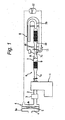
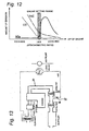
- Fig. 1 is a schematic diagram for explaining a four-cycle engine according to an embodiment of the aspects 1, 2 and 3.
- reference numeral 1 denotes a four-cycle engine which is adopted in an autobicycle such as a motorcycle or a scooter.
- An intake passage 2 is connected to an intake port (not shown) of the engine 1
- a carburetor 3 serving as a fuel supply system is interposed in the middle of the intake passage 2
- an air cleaner 4 is connected to an upstream end of the intake passage 2.
- This air cleaner 4 has a structure in which the inside of a cleaner case 4a is demarcated into an air suction side "a" and an emission side "b” by an element 5.
- the carburetor 3 includes a slow system, which operates in idling and low-speed traveling areas, and a main system, which operates in medium-speed and high-speed traveling areas. In all the operation areas, an air fuel ratio is set to be richer than a theoretical air fuel ratio.
- An exhaust gas passage 6 is connected to an exhaust port (not shown) of the engine 1.
- This exhaust gas passage 6 includes an exhaust pipe 7, which is connected to the exhaust port, and a muffler 8, which is disposed on downstream side of the exhaust pipe 7.
- the exhaust pipe 7 has an upstream side half portion 7a and a downstream side half portion 7b, which is bent and formed in generally a U shape.
- the downstream side half portion 7b is housed in the muffler 8.
- This exhaust gas purifier has a structure in which a first catalyst 9, which mainly has a reduction action, is disposed in the upstream side half portion 7a of the exhaust pipe 7, a second catalyst 10, which mainly has an oxidation action, is disposed in the downstream side half portion 7b located downstream of the first catalyst 9, and secondary air induction portion 7c is formed between the first and the second catalysts 9 and 10.
- An inner diameter d1 of the portions, where the first and the second catalysts 9 and 10 are arranged, of the exhaust pipe 7 is formed larger than an inner diameter d2 of remaining portions thereof, and the first and the second catalysts 9 and 10 are housed in the large diameter portions.
- the secondary air induction port 7c is located in a small diameter portion between the first and the second catalysts 9 and 10 of the exhaust pipe 7. Since the secondary air induction port 7c is formed in the small diameter portion between the large diameter portions, in which the first and the second catalysts 9 and 10 are housed, in this way, exhaust gas flow velocity in this portion increases, and a negative pressure is generated in the portion of the induction port 7c by a so-called Venturi effect, whereby a suction amount of the secondary air can be increased.
- the Venturi effect cannot be obtained sufficiently, and an intake amount of the secondary air cannot be increased.
- a secondary air supply system is connected to the secondary air induction portion 7c.
- This secondary air supply system has a structure in which an emission side "b" of the air cleaner 4 and the secondary air intake port 7c are communicatively connected by secondary air induction pipe 11, and a lead valve 12, which functions as a check valve, is interposed in the middle of the secondary air supply pipe 11.
- This lead valve 12 allows only a flow of the secondary air from the air cleaner 4 side to the exhaust gas passage 6 side and prevents a flow in the opposite direction. More specifically, a negative pressure is generated in the exhaust gas passage 6 by exhaust pulsation caused by opening and closing of intake and exhaust valves (not shown) of the engine 1, and the air in the emission side "b" of the air cleaner 4 is sucked by this negative pressure. Note that the secondary air may be pressurized and supplied by an air pump instead of the lead valve 12.
- the secondary air induction pipe 11 is connected to an upstream end of the portion of the downstream side half portion 7b located inside the muffler 8 and is supported by and fixed to the muffler 8 together with the downstream side half portion 7b.
- An arrangement position of the first catalyst 9 is set in a position where a temperature of exhaust gas, which enters the first catalyst 9, that is, an entering gas temperature rises to 300°C or more at a time when purification of the exhaust gas is desired to be started.
- This entering gas temperature is a standard of a temperature essential for activation of the first catalyst 9 to be performed surely. More specifically, the first catalyst 9 is arranged in a position 300 to 500 mm from an exhaust port in the case of an engine with a displacement of about 50 cc.
- a temperature of exhaust gas entering the second catalyst 10 is affected by the first catalyst 9 located on the upstream side and the secondary air to be introduced.
- An arrangement position of the second catalyst 10 is set in a position where an entering gas temperature of the exhaust gas entering the second catalyst 10 rises to 300°C or more at a time when purification of the exhaust gas is desired to be started under such a situation. More specifically, the second catalyst 10 is arranged in a position about 200 mm from the first catalyst 9 in the case of the engine with a displacement of about 50 cc.
- the secondary air induction portion 7c is set in a position where a difference between highest temperatures in the measurement operation areas of the first and the second catalysts 9 and 10 is within a predetermined range, more specifically, 100°C. Note that a connection position where the temperature difference is reduced to 100°C or less is found by an experiment.
- the secondary air induction pipe 11 is connected in a range up to generally about 1/2 of an interval from the first catalyst 9 to the second catalyst 10 and, more desirably, a portion closest to the first catalyst 9.
- the secondary air induction pipe 11 is connected to the position where a difference between maximum temperatures in the measurement operation areas of the first and the second catalysts 9 and 10 is reduced to 100°C or less, the deviation of burden due to the temperature difference of the first and the second catalysts 9 and 10 can be controlled, and as a result, the deterioration of the second catalyst 10 can be controlled, and a usable life thereof can be extended.
- the secondary air induction pipe 11 when the secondary air induction pipe 11 is brought close to the side of the first catalyst 9 or the second catalyst 10, a temperature of the catalyst on the side, to which the secondary air induction pipe 11 is brought close, tends to be higher than the other catalyst. Consequently, the secondary air induction pipe 11 is connected to a position where the temperature difference of the first and the second catalysts 9 and 10 is as small as possible, more specifically, a range up to generally about 1/2 of the interval from the first catalyst 9 to the second catalyst 10, whereby a situation in which a high-temperature state last for a long time can be prevented.
- the second catalyst 10 is disposed in the muffler 8 in which the downstream side half portion 7b of the exhaust pipe 7 is housed, it becomes possible to increase a capacity of the second catalyst 10 without spoiling the appearance, and a purification ability can be improved.
- the second catalyst 10 is disposed in the muffler 8, the second catalyst 10 is never cooled by the external air, and time until the second catalyst 10 reaches the activation temperature at the cold start time of the engine 1 can be reduced.
- the secondary air induction pipe 11 since the secondary air induction pipe 11 is connected to the downstream side half portion 7b located inside the muffler 8, the secondary air induction pipe 11 can be supported and fixed by the exhaust pipe 7 and the muffler8, andconnection strengthof the secondary air induction pipe 11 can be improved without spoiling the appearance.
- This experiment was performed for finding a connection position of the secondary air induction port 11 where the maximum temperature difference in the measurement operation area of the first and the second catalysts 9 and 10 was reduced to 100°C or less.
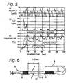
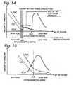
- an exhaust gas purifier with the same structure as the above-mentioned embodiment was adopted, and a so-called ECE40 test method for adjusting traveling time and traveling velocity in accordance with a traveling pattern set in advance was adopted. More specifically, an autobicycle repeated a traveling pattern of 200 seconds, which changed the traveling velocity to about 15 km/h, 30 km/h, and 50 km/h, six times to travel 1200 seconds in total, and changes in an amount of emission of CO and temperatures of the first and the second catalysts were measured (see (a) to (c) of Figs. 3 , 5 and 7 ). In addition, an amount of secondary air introduced during 1200 seconds was set to about 370 to 400 liters.
- An experiment example 1 was performed with the secondary air induction pipe 11 connected to a position on the downstream side 20 mm from a rear end surface of the first catalyst 9 (see Fig. 2 ).
- an experiment example 2 was performed with the secondary air induction pipe 11 connected to a position on the downstream side 60 mm from the rear end surface of the fist catalyst 9 (see Fig. 4 )
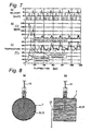
- a third experiment example 3 was performed with the secondary air induction pipe 11 connected to a position on the downstream side 120 mm from the rear end surface of the first catalyst 9 (see Fig. 6 ).
- a change in a temperature of each of the first and the second catalysts 9 and 10 was measured, and an amount of CO was measured. Note that in the experiment examples 1 to 3, capacities of the first and the second catalysts 9 and 10 and engine specifications are assumed to be the same.
- Figs. 8 (a) and (b) show a temperature measurement method for the respective catalysts 9 and 10.
- a hole of about 3 mm ⁇ was opened in the exhaust pipe and the catalysts 9 and 10 in a radial direction from the outside, and a sheath K type thermo-couple 15 was inserted and fixed in this hole such that a tip of the thermo-couple 15 was located in centers of the catalysts 9 and 10.
- the thermo-couple 15 may be inserted in an axial direction of the catalysts 9 and 10.
- the difference between the maximum temperatures of the first and the second catalysts was within 100°C, for example, 20°C, 60°C and 90°C, respectively, and satisfactory values were obtained as the amount of emission of CO as well.
- arrangement positions of the first and the second catalysts 9 and 10 are set on the basis of a time when the catalysts are desired to be activated and an entering gas temperature, and a connection position of the secondary air induction pipe 11 is subsequently set such that the maximum temperature difference of the first and the second catalysts 9 and 10 is within 100°C, whereby deterioration of the catalysts can be controlled.
- an emission level of CO in the experiment example 1 is about 200 ppm (see Fig. 3(b) ), which is smaller than that of about 400 ppm in the experiment example 3 (see Fig. 7(b) ). It is considered that it is only when capacities of catalysts are changed that a difference occurs in a removal level of CO in a state in which activation states of the first and the second catalysts are substantially the same and the same secondary air is supplied.
- the first catalysts in the experiment examples 1 and 3 are identical, it is evident that a part of the first catalyst contributes to the removal of CO.
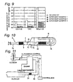
- Fig. 9 is a diagram in which mode exhaust gas values according to the experiment examples 1 to 3 are arranged.
- a removal rate of CO and HC is high at 75 to 80%, and a removal rate NOx is also high at 70 to 75%.
- the present invention is also applicable to a four-cycle engine which detects oxygen concentration in exhaust gas and feedback-controls an amount of fuel injection to an engine such that an air fuel ratio, which is found on the basis of the oxygen concentration, is set as a target air fuel ratio.
- an air fuel ratio which is found on the basis of the oxygen concentration
Landscapes
- Engineering & Computer Science (AREA)
- Chemical & Material Sciences (AREA)
- Chemical Kinetics & Catalysis (AREA)
- Combustion & Propulsion (AREA)
- Mechanical Engineering (AREA)
- General Engineering & Computer Science (AREA)
- Health & Medical Sciences (AREA)
- Toxicology (AREA)
- Exhaust Gas After Treatment (AREA)
- Valve Device For Special Equipments (AREA)
Claims (5)
- Viertakt- Motor, in dem ein Abgasrohr (7) mit einer Abgasöffnung der Brennkraftmaschine verbunden ist, mit einem Abgasreiniger mit zumindest einem ersten und zweiten Katalysator (9, 10), angeordnet in dem Abgasrohr (7), wobei der zweite Katalysator (10) in einem vorbestimmten Abstand entfernt von dem ersten Katalysator (9) in dem Abgasrohr (7) stromab des ersten Katalysators (9) angeordnet ist, wobei Sekundärluft in das Abgasrohr (7) zwischen dem ersten und zweiten Katalysator (9, 10) durch ein Sekundärluft- Einleitungsrohr (11) eingeleitet wird, dadurch gekennzeichnet, dass die Position (7c) der Verbindung des Sekundärluft- Einleitungsrohres (11) in dem Abgasrohr (7) derart festgelegt wird, dass eine Temperaturdifferenz zwischen den Katalysatoren (9, 10) in einem Messbereich von einer Brennkraftmaschinen- Kaltstartoperation innerhalb eines vorbestimmten Bereiches ist, bis eine vorbestimmte Operationszeit vergeht.
- Viertakt- Motor nach Anspruch 1, gekennzeichnet durch einen Schalldämpfer (8), der einen Teil des Abgasrohres (7) umgibt, wobei der erste Katalysator (9) stromauf des Schalldämpfers (8) angeordnet ist und wobei der zweite Katalysator (10) innerhalb des Schalldämpfers (8) angeordnet ist.
- Viertakt- Motor nach Anspruch 2, dadurch gekennzeichnet, dass das Sekundärluft- Einleitungsrohr (11) mit einem Teil des Abgasrohres (7), angeordnet stromauf des zweiten Katalysators (10) und innerhalb des Schalldämpfers (8), verbunden ist.
- Viertakt- Motor nach einem der Ansprüche 1 bis 3, dadurch gekennzeichnet, dass die Sekundärluft- Einleitungsöffnung (7c) in einem Abschnitt (d2) mit kleinem Durchmesser des Abgasrohres (7), angeordnet zwischen dem ersten und zweiten Katalysator (9, 10), platziert ist.
- Verfahren zum Reinigen eines Abgases eines Viertakt- Motors, in dem ein Abgasrohr (7) mit einer Abgasöffnung der Brennkraftmaschine verbunden ist, mit einem Abgasreiniger mit zumindest einem ersten und zweiten Katalysator (9, 10), angeordnet in dem Abgasrohr (7), wobei der zweite Katalysator (10) in einem vorbestimmten Abstand entfernt von dem ersten Katalysator (9) in dem Abgasrohr (7) stromab des ersten Katalysators (9) angeordnet ist, wobei das Verfahren aufweist:Einleiten von Sekundärluft in das Abgasrohr (7) zwischen den ersten und zweiten Katalysator (9, 10) durch ein Sekundärluft- Einleitungsrohr (11), wobei die Position (7c) der Verbindung des zweiten Sekundärluft- Einleitungsrohres (11) in dem Abgasrohr (7) derart festgelegt ist, dass eine Temperaturdifferenz zwischen den Katalysatoren (9, 10) in einem Messbereich von einer Brennkraftmaschinen- Kaltstartoperation innerhalb eines vorbestimmten Bereiches ist, bis eine vorbestimmte Operationszeit vergeht.
Priority Applications (1)
| Application Number | Priority Date | Filing Date | Title |
|---|---|---|---|
| EP09010830A EP2119884B1 (de) | 2003-06-19 | 2004-06-07 | Viertaktmotor |
Applications Claiming Priority (3)
| Application Number | Priority Date | Filing Date | Title |
|---|---|---|---|
| JP2003174735 | 2003-06-19 | ||
| JP2004084603 | 2004-03-23 | ||
| PCT/JP2004/007924 WO2004113696A1 (ja) | 2003-06-19 | 2004-06-07 | 4サイクルエンジン |
Related Child Applications (2)
| Application Number | Title | Priority Date | Filing Date |
|---|---|---|---|
| EP09010830A Division EP2119884B1 (de) | 2003-06-19 | 2004-06-07 | Viertaktmotor |
| EP09010830.9 Division-Into | 2009-08-24 |
Publications (3)
| Publication Number | Publication Date |
|---|---|
| EP1640581A1 EP1640581A1 (de) | 2006-03-29 |
| EP1640581A4 EP1640581A4 (de) | 2009-07-29 |
| EP1640581B1 true EP1640581B1 (de) | 2011-10-12 |
Family
ID=33543478
Family Applications (2)
| Application Number | Title | Priority Date | Filing Date |
|---|---|---|---|
| EP09010830A Expired - Lifetime EP2119884B1 (de) | 2003-06-19 | 2004-06-07 | Viertaktmotor |
| EP04745634A Expired - Lifetime EP1640581B1 (de) | 2003-06-19 | 2004-06-07 | Viertaktmotor |
Family Applications Before (1)
| Application Number | Title | Priority Date | Filing Date |
|---|---|---|---|
| EP09010830A Expired - Lifetime EP2119884B1 (de) | 2003-06-19 | 2004-06-07 | Viertaktmotor |
Country Status (8)
| Country | Link |
|---|---|
| US (1) | US7448204B2 (de) |
| EP (2) | EP2119884B1 (de) |
| JP (1) | JP4234716B2 (de) |
| AT (1) | ATE528492T1 (de) |
| ES (1) | ES2387935T3 (de) |
| MY (1) | MY141622A (de) |
| TW (1) | TWI296022B (de) |
| WO (1) | WO2004113696A1 (de) |
Families Citing this family (21)
| Publication number | Priority date | Publication date | Assignee | Title |
|---|---|---|---|---|
| JP2006199175A (ja) * | 2005-01-21 | 2006-08-03 | Yamaha Motor Co Ltd | スノーモービル |
| JP2006199176A (ja) * | 2005-01-21 | 2006-08-03 | Yamaha Motor Co Ltd | スノーモービルの排気装置 |
| JP2006291929A (ja) * | 2005-04-14 | 2006-10-26 | Yamaha Motor Co Ltd | 排気ガス浄化機能を有するエンジン |
| CN1936288B (zh) * | 2005-09-19 | 2010-05-26 | 徐楠 | 环保的机动车尾气净化消声器 |
| JP4372764B2 (ja) * | 2006-03-30 | 2009-11-25 | トヨタ自動車株式会社 | 排ガス浄化装置 |
| JP2007297984A (ja) * | 2006-05-01 | 2007-11-15 | Yamaha Motor Co Ltd | 排気装置およびその排気装置を備えた車両 |
| JP2008064068A (ja) * | 2006-09-11 | 2008-03-21 | Yamaha Motor Co Ltd | 自動二輪車 |
| JP4871107B2 (ja) * | 2006-12-06 | 2012-02-08 | ヤマハ発動機株式会社 | 鞍乗り型車両 |
| DE602008000202D1 (de) * | 2007-03-13 | 2009-11-26 | Yamaha Motor Co Ltd | Abgasreinigungssystem für einen Verbrennungsmotor |
| DE102007062663A1 (de) * | 2007-12-24 | 2009-06-25 | J. Eberspächer GmbH & Co. KG | Schiebesitz sowie Rohranordnung und Abgasbehandlungseinrichtung |
| US8136350B2 (en) * | 2008-05-28 | 2012-03-20 | Briggs & Stratton Corporation | Catalytic muffler having crossover passageway for secondary air |
| US8661786B2 (en) * | 2008-07-01 | 2014-03-04 | Woodward, Inc. | Passive secondary air delivery system for two bed catalyst system |
| JP2010101310A (ja) * | 2008-09-26 | 2010-05-06 | Yamaha Motor Co Ltd | 鞍乗り型車両 |
| US8485313B2 (en) | 2010-06-18 | 2013-07-16 | Briggs & Stratton Corporation | Muffler and engine system |
| JP5549656B2 (ja) * | 2011-09-27 | 2014-07-16 | トヨタ自動車株式会社 | 内燃機関の排気浄化装置 |
| US9149768B1 (en) * | 2014-03-27 | 2015-10-06 | General Electric Company | Emission control in rich burn natural gas engines |
| US9746176B2 (en) | 2014-06-04 | 2017-08-29 | Lochinvar, Llc | Modulating burner with venturi damper |
| JP6002257B2 (ja) * | 2015-02-04 | 2016-10-05 | 富士重工業株式会社 | 排気マフラ |
| DE102017010825B4 (de) * | 2017-11-23 | 2025-11-13 | Mercedes-Benz Group AG | Verfahren zum Betreiben einer Abgasanlage mit einem ersten SCR-Katalysator und einem zweiten SCR-Katalysator |
| US11428181B2 (en) * | 2020-03-25 | 2022-08-30 | Cummins Inc. | Systems and methods for ultra-low NOx cold start warmup control and fault diagnosis |
| US11624333B2 (en) | 2021-04-20 | 2023-04-11 | Kohler Co. | Exhaust safety system for an engine |
Family Cites Families (27)
| Publication number | Priority date | Publication date | Assignee | Title |
|---|---|---|---|---|
| US3041149A (en) * | 1958-08-07 | 1962-06-26 | Oxy Catalyst Inc | Catalytic muffler |
| BE622426A (de) * | 1961-09-15 | |||
| US3402550A (en) * | 1964-05-14 | 1968-09-24 | Texaco Inc | Over temperature protection device for a catalytic muffler for exhaust emissions control in an internal combustion engine system |
| DE2337228A1 (de) * | 1973-07-21 | 1975-02-06 | Daimler Benz Ag | Brennkraftmaschine mit einer auslassleitung mit reduktionskatalysator und oxydationskatalysator |
| JPS5359014U (de) * | 1976-10-22 | 1978-05-19 | ||
| JPS5359014A (en) | 1976-11-10 | 1978-05-27 | Geran Kk | Slurry explosive composition containing sodium montmorillonite |
| JPS5818547A (ja) | 1981-07-23 | 1983-02-03 | Yamaha Motor Co Ltd | 蒸発ガソリン燃焼装置 |
| JPS6170118A (ja) | 1984-09-14 | 1986-04-10 | Yamaha Motor Co Ltd | 自動車エンジンの排気装置 |
| JPH07101008B2 (ja) | 1986-01-14 | 1995-11-01 | ヤマハ発動機株式会社 | 多気筒エンジンの吸気装置 |
| JPS62228622A (ja) | 1986-03-31 | 1987-10-07 | Yamaha Motor Co Ltd | エンジンの吸気装置 |
| JP2759461B2 (ja) | 1988-10-12 | 1998-05-28 | ヤマハ発動機株式会社 | エンジンの吸気装置 |
| JPH0518234A (ja) * | 1991-07-12 | 1993-01-26 | Japan Electron Control Syst Co Ltd | 内燃機関の二次空気制御装置 |
| JPH0598955A (ja) | 1991-10-12 | 1993-04-20 | Mazda Motor Corp | エンジンの二次空気制御装置 |
| JP3172232B2 (ja) | 1991-10-15 | 2001-06-04 | ヤマハ発動機株式会社 | エンジンの燃焼制御装置 |
| JPH0622554U (ja) * | 1992-08-28 | 1994-03-25 | 富士重工業株式会社 | エンジンの排気ガス再循環装置 |
| US6000217A (en) * | 1995-01-04 | 1999-12-14 | Engelhard Corporation | Air injection strategies for effectively burning hydrocarbons released from a hydrocarbon trap |
| US5822976A (en) * | 1995-04-05 | 1998-10-20 | Ford Global Technologies, Inc. | Method and system for controlling the amount of secondary air introduced into an internal combustion engine |
| JPH09133016A (ja) * | 1995-11-09 | 1997-05-20 | Toyota Motor Corp | 内燃機関の排気浄化装置 |
| DE69709977T2 (de) | 1996-05-02 | 2002-06-06 | Kubota Corp., Osaka | Verfahren zum Befestigen einer Kraftstoffeinspritzvorrichtung an einen Motor |
| JP3191003B2 (ja) | 1996-09-06 | 2001-07-23 | 株式会社クボタ | ディーゼルエンジンの副室式燃焼室 |
| US5746049A (en) * | 1996-12-13 | 1998-05-05 | Ford Global Technologies, Inc. | Method and apparatus for estimating and controlling no x trap temperature |
| US5804147A (en) * | 1997-02-03 | 1998-09-08 | General Motors Corporation | Exhaust gas management apparatus and method |
| JP3523529B2 (ja) | 1999-06-15 | 2004-04-26 | 株式会社クボタ | エンジンのダイレクト型吸気ポート、およびヘリカル型吸気ポート |
| JP2001173437A (ja) * | 1999-12-17 | 2001-06-26 | Denso Corp | 内燃機関の排ガス浄化装置 |
| DE10038724A1 (de) * | 2000-08-09 | 2002-02-21 | Porsche Ag | Verfahren und Vorrichtung zur katalytischen Abgasnachbehandlung des Abgases einer Brennkraftmaschine |
| JP2002161737A (ja) | 2000-11-29 | 2002-06-07 | Sanshin Ind Co Ltd | エンジンにおける排気浄化装置、およびこの装置を搭載した小型船舶 |
| FR2827632B1 (fr) * | 2001-07-19 | 2003-12-05 | Renault | Procede et dispositif de reduction d'emission polluante |
-
2004
- 2004-05-26 MY MYPI20042011A patent/MY141622A/en unknown
- 2004-06-07 AT AT04745634T patent/ATE528492T1/de not_active IP Right Cessation
- 2004-06-07 WO PCT/JP2004/007924 patent/WO2004113696A1/ja not_active Ceased
- 2004-06-07 JP JP2005507196A patent/JP4234716B2/ja not_active Expired - Fee Related
- 2004-06-07 EP EP09010830A patent/EP2119884B1/de not_active Expired - Lifetime
- 2004-06-07 EP EP04745634A patent/EP1640581B1/de not_active Expired - Lifetime
- 2004-06-07 ES ES09010830T patent/ES2387935T3/es not_active Expired - Lifetime
- 2004-06-08 TW TW093116433A patent/TWI296022B/zh active
-
2005
- 2005-12-19 US US11/311,067 patent/US7448204B2/en not_active Expired - Fee Related
Also Published As
| Publication number | Publication date |
|---|---|
| EP1640581A4 (de) | 2009-07-29 |
| ATE528492T1 (de) | 2011-10-15 |
| WO2004113696A1 (ja) | 2004-12-29 |
| US7448204B2 (en) | 2008-11-11 |
| US20060150617A1 (en) | 2006-07-13 |
| EP2119884A1 (de) | 2009-11-18 |
| MY141622A (en) | 2010-05-31 |
| JP4234716B2 (ja) | 2009-03-04 |
| TWI296022B (en) | 2008-04-21 |
| JPWO2004113696A1 (ja) | 2006-07-20 |
| EP1640581A1 (de) | 2006-03-29 |
| TW200504278A (en) | 2005-02-01 |
| ES2387935T3 (es) | 2012-10-04 |
| EP2119884B1 (de) | 2012-06-27 |
Similar Documents
| Publication | Publication Date | Title |
|---|---|---|
| EP1640581B1 (de) | Viertaktmotor | |
| US11174801B2 (en) | Engine and vehicle having throttle control | |
| US5842341A (en) | Exhaust emission purification apparatus for an internal combustion engine | |
| US6260353B1 (en) | NOx reduction system for combustion exhaust gas | |
| EP0761286B1 (de) | Verfahren zum Reinigen von Verbrennungsmotorabgas | |
| EP1443195B1 (de) | Abgasemissionsregelsystem | |
| US5873242A (en) | Apparatus for purifying exhaust gas | |
| US20040128985A1 (en) | Exhaust gas purification device | |
| US6637191B1 (en) | Method and system for diagnosing a secondary air supply for an internal combustion engine | |
| US20030097833A1 (en) | Nox purge air/fuel ratio selection | |
| US6334306B1 (en) | Exhaust gas purification apparatus in combustion engine | |
| EP2075427B1 (de) | Sekundärluftzuführsystem und Fahrzeug | |
| EP1970546B1 (de) | Abgassystem und Verfahren zur Steuerung eines Motors eines Zweiradfahrzeugs | |
| EP2075445B1 (de) | Sekundärluftzuführsystem und Fahrzeug | |
| JP2004028030A (ja) | 内燃機関の排気浄化装置 | |
| CN100389248C (zh) | 四冲程发动机 | |
| JP2005155532A (ja) | 排気浄化装置 | |
| JP2009013791A (ja) | 異常検出装置、異常検出方法、及び排気浄化制御装置 | |
| JPH11311118A (ja) | ターボチャージャ付エンジンの排気ガス浄化装置、及びその制御方法 | |
| JP2006220019A (ja) | エンジンの排ガス浄化装置 | |
| KR20080054818A (ko) | 차량의 배기가스 정화장치 및 그 방법 | |
| JP2803530B2 (ja) | 排気ガス浄化装置 | |
| JP2006077608A (ja) | 排気浄化装置 | |
| JPH059453Y2 (de) | ||
| JPH04330320A (ja) | エアサクションシステム |
Legal Events
| Date | Code | Title | Description |
|---|---|---|---|
| PUAI | Public reference made under article 153(3) epc to a published international application that has entered the european phase |
Free format text: ORIGINAL CODE: 0009012 |
|
| 17P | Request for examination filed |
Effective date: 20051219 |
|
| AK | Designated contracting states |
Kind code of ref document: A1 Designated state(s): AT BE BG CH CY CZ DE DK EE ES FI FR GB GR HU IE IT LI LU MC NL PL PT RO SE SI SK TR |
|
| DAX | Request for extension of the european patent (deleted) | ||
| A4 | Supplementary search report drawn up and despatched |
Effective date: 20090626 |
|
| 17Q | First examination report despatched |
Effective date: 20091008 |
|
| GRAP | Despatch of communication of intention to grant a patent |
Free format text: ORIGINAL CODE: EPIDOSNIGR1 |
|
| GRAS | Grant fee paid |
Free format text: ORIGINAL CODE: EPIDOSNIGR3 |
|
| GRAA | (expected) grant |
Free format text: ORIGINAL CODE: 0009210 |
|
| AK | Designated contracting states |
Kind code of ref document: B1 Designated state(s): AT BE BG CH CY CZ DE DK EE ES FI FR GB GR HU IE IT LI LU MC NL PL PT RO SE SI SK TR |
|
| REG | Reference to a national code |
Ref country code: GB Ref legal event code: FG4D |
|
| REG | Reference to a national code |
Ref country code: CH Ref legal event code: EP |
|
| REG | Reference to a national code |
Ref country code: IE Ref legal event code: FG4D |
|
| REG | Reference to a national code |
Ref country code: ES Ref legal event code: FG2A Ref document number: 2371023 Country of ref document: ES Kind code of ref document: T3 Effective date: 20111226 |
|
| REG | Reference to a national code |
Ref country code: DE Ref legal event code: R096 Ref document number: 602004034827 Country of ref document: DE Effective date: 20120105 |
|
| REG | Reference to a national code |
Ref country code: NL Ref legal event code: VDEP Effective date: 20111012 |
|
| REG | Reference to a national code |
Ref country code: GR Ref legal event code: EP Ref document number: 20110402980 Country of ref document: GR Effective date: 20120206 |
|
| REG | Reference to a national code |
Ref country code: AT Ref legal event code: MK05 Ref document number: 528492 Country of ref document: AT Kind code of ref document: T Effective date: 20111012 |
|
| PG25 | Lapsed in a contracting state [announced via postgrant information from national office to epo] |
Ref country code: BE Free format text: LAPSE BECAUSE OF FAILURE TO SUBMIT A TRANSLATION OF THE DESCRIPTION OR TO PAY THE FEE WITHIN THE PRESCRIBED TIME-LIMIT Effective date: 20111012 |
|
| PG25 | Lapsed in a contracting state [announced via postgrant information from national office to epo] |
Ref country code: SE Free format text: LAPSE BECAUSE OF FAILURE TO SUBMIT A TRANSLATION OF THE DESCRIPTION OR TO PAY THE FEE WITHIN THE PRESCRIBED TIME-LIMIT Effective date: 20111012 Ref country code: NL Free format text: LAPSE BECAUSE OF FAILURE TO SUBMIT A TRANSLATION OF THE DESCRIPTION OR TO PAY THE FEE WITHIN THE PRESCRIBED TIME-LIMIT Effective date: 20111012 Ref country code: PT Free format text: LAPSE BECAUSE OF FAILURE TO SUBMIT A TRANSLATION OF THE DESCRIPTION OR TO PAY THE FEE WITHIN THE PRESCRIBED TIME-LIMIT Effective date: 20120213 Ref country code: SI Free format text: LAPSE BECAUSE OF FAILURE TO SUBMIT A TRANSLATION OF THE DESCRIPTION OR TO PAY THE FEE WITHIN THE PRESCRIBED TIME-LIMIT Effective date: 20111012 |
|
| PG25 | Lapsed in a contracting state [announced via postgrant information from national office to epo] |
Ref country code: CY Free format text: LAPSE BECAUSE OF FAILURE TO SUBMIT A TRANSLATION OF THE DESCRIPTION OR TO PAY THE FEE WITHIN THE PRESCRIBED TIME-LIMIT Effective date: 20111012 |
|
| PG25 | Lapsed in a contracting state [announced via postgrant information from national office to epo] |
Ref country code: EE Free format text: LAPSE BECAUSE OF FAILURE TO SUBMIT A TRANSLATION OF THE DESCRIPTION OR TO PAY THE FEE WITHIN THE PRESCRIBED TIME-LIMIT Effective date: 20111012 Ref country code: SK Free format text: LAPSE BECAUSE OF FAILURE TO SUBMIT A TRANSLATION OF THE DESCRIPTION OR TO PAY THE FEE WITHIN THE PRESCRIBED TIME-LIMIT Effective date: 20111012 Ref country code: DK Free format text: LAPSE BECAUSE OF FAILURE TO SUBMIT A TRANSLATION OF THE DESCRIPTION OR TO PAY THE FEE WITHIN THE PRESCRIBED TIME-LIMIT Effective date: 20111012 Ref country code: CZ Free format text: LAPSE BECAUSE OF FAILURE TO SUBMIT A TRANSLATION OF THE DESCRIPTION OR TO PAY THE FEE WITHIN THE PRESCRIBED TIME-LIMIT Effective date: 20111012 Ref country code: BG Free format text: LAPSE BECAUSE OF FAILURE TO SUBMIT A TRANSLATION OF THE DESCRIPTION OR TO PAY THE FEE WITHIN THE PRESCRIBED TIME-LIMIT Effective date: 20120112 |
|
| PLBE | No opposition filed within time limit |
Free format text: ORIGINAL CODE: 0009261 |
|
| STAA | Information on the status of an ep patent application or granted ep patent |
Free format text: STATUS: NO OPPOSITION FILED WITHIN TIME LIMIT |
|
| PG25 | Lapsed in a contracting state [announced via postgrant information from national office to epo] |
Ref country code: PL Free format text: LAPSE BECAUSE OF FAILURE TO SUBMIT A TRANSLATION OF THE DESCRIPTION OR TO PAY THE FEE WITHIN THE PRESCRIBED TIME-LIMIT Effective date: 20111012 Ref country code: RO Free format text: LAPSE BECAUSE OF FAILURE TO SUBMIT A TRANSLATION OF THE DESCRIPTION OR TO PAY THE FEE WITHIN THE PRESCRIBED TIME-LIMIT Effective date: 20111012 |
|
| 26N | No opposition filed |
Effective date: 20120713 |
|
| REG | Reference to a national code |
Ref country code: DE Ref legal event code: R097 Ref document number: 602004034827 Country of ref document: DE Effective date: 20120713 |
|
| PG25 | Lapsed in a contracting state [announced via postgrant information from national office to epo] |
Ref country code: AT Free format text: LAPSE BECAUSE OF FAILURE TO SUBMIT A TRANSLATION OF THE DESCRIPTION OR TO PAY THE FEE WITHIN THE PRESCRIBED TIME-LIMIT Effective date: 20111012 Ref country code: MC Free format text: LAPSE BECAUSE OF NON-PAYMENT OF DUE FEES Effective date: 20120630 |
|
| REG | Reference to a national code |
Ref country code: CH Ref legal event code: PL |
|
| REG | Reference to a national code |
Ref country code: CH Ref legal event code: PL |
|
| GBPC | Gb: european patent ceased through non-payment of renewal fee |
Effective date: 20120607 |
|
| REG | Reference to a national code |
Ref country code: IE Ref legal event code: MM4A |
|
| REG | Reference to a national code |
Ref country code: DE Ref legal event code: R119 Ref document number: 602004034827 Country of ref document: DE Effective date: 20130101 |
|
| PG25 | Lapsed in a contracting state [announced via postgrant information from national office to epo] |
Ref country code: GB Free format text: LAPSE BECAUSE OF NON-PAYMENT OF DUE FEES Effective date: 20120607 Ref country code: CH Free format text: LAPSE BECAUSE OF NON-PAYMENT OF DUE FEES Effective date: 20120630 Ref country code: DE Free format text: LAPSE BECAUSE OF NON-PAYMENT OF DUE FEES Effective date: 20130101 Ref country code: IE Free format text: LAPSE BECAUSE OF NON-PAYMENT OF DUE FEES Effective date: 20120607 Ref country code: LI Free format text: LAPSE BECAUSE OF NON-PAYMENT OF DUE FEES Effective date: 20120630 |
|
| PG25 | Lapsed in a contracting state [announced via postgrant information from national office to epo] |
Ref country code: FI Free format text: LAPSE BECAUSE OF FAILURE TO SUBMIT A TRANSLATION OF THE DESCRIPTION OR TO PAY THE FEE WITHIN THE PRESCRIBED TIME-LIMIT Effective date: 20111012 |
|
| PG25 | Lapsed in a contracting state [announced via postgrant information from national office to epo] |
Ref country code: LU Free format text: LAPSE BECAUSE OF NON-PAYMENT OF DUE FEES Effective date: 20120607 |
|
| PG25 | Lapsed in a contracting state [announced via postgrant information from national office to epo] |
Ref country code: HU Free format text: LAPSE BECAUSE OF FAILURE TO SUBMIT A TRANSLATION OF THE DESCRIPTION OR TO PAY THE FEE WITHIN THE PRESCRIBED TIME-LIMIT Effective date: 20040607 |
|
| REG | Reference to a national code |
Ref country code: FR Ref legal event code: PLFP Year of fee payment: 12 |
|
| PGFP | Annual fee paid to national office [announced via postgrant information from national office to epo] |
Ref country code: ES Payment date: 20150626 Year of fee payment: 12 |
|
| PGFP | Annual fee paid to national office [announced via postgrant information from national office to epo] |
Ref country code: GR Payment date: 20150611 Year of fee payment: 12 Ref country code: IT Payment date: 20150622 Year of fee payment: 12 Ref country code: FR Payment date: 20150619 Year of fee payment: 12 |
|
| PGFP | Annual fee paid to national office [announced via postgrant information from national office to epo] |
Ref country code: TR Payment date: 20160525 Year of fee payment: 13 |
|
| REG | Reference to a national code |
Ref country code: GR Ref legal event code: ML Ref document number: 20110402980 Country of ref document: GR Effective date: 20170109 |
|
| REG | Reference to a national code |
Ref country code: FR Ref legal event code: ST Effective date: 20170228 |
|
| PG25 | Lapsed in a contracting state [announced via postgrant information from national office to epo] |
Ref country code: FR Free format text: LAPSE BECAUSE OF NON-PAYMENT OF DUE FEES Effective date: 20160630 Ref country code: GR Free format text: LAPSE BECAUSE OF NON-PAYMENT OF DUE FEES Effective date: 20170109 |
|
| PG25 | Lapsed in a contracting state [announced via postgrant information from national office to epo] |
Ref country code: IT Free format text: LAPSE BECAUSE OF NON-PAYMENT OF DUE FEES Effective date: 20160607 |
|
| PG25 | Lapsed in a contracting state [announced via postgrant information from national office to epo] |
Ref country code: ES Free format text: LAPSE BECAUSE OF NON-PAYMENT OF DUE FEES Effective date: 20160608 |
|
| REG | Reference to a national code |
Ref country code: ES Ref legal event code: FD2A Effective date: 20180626 |
|
| PG25 | Lapsed in a contracting state [announced via postgrant information from national office to epo] |
Ref country code: TR Free format text: LAPSE BECAUSE OF NON-PAYMENT OF DUE FEES Effective date: 20170607 |