EP1634723B1 - Bindevorrichtung für ablagewerkzeug - Google Patents
Bindevorrichtung für ablagewerkzeug Download PDFInfo
- Publication number
- EP1634723B1 EP1634723B1 EP04724801.8A EP04724801A EP1634723B1 EP 1634723 B1 EP1634723 B1 EP 1634723B1 EP 04724801 A EP04724801 A EP 04724801A EP 1634723 B1 EP1634723 B1 EP 1634723B1
- Authority
- EP
- European Patent Office
- Prior art keywords
- parts
- locking
- key
- shaped
- binder
- Prior art date
- Legal status (The legal status is an assumption and is not a legal conclusion. Google has not performed a legal analysis and makes no representation as to the accuracy of the status listed.)
- Expired - Lifetime
Links
Images






Classifications
-
- B—PERFORMING OPERATIONS; TRANSPORTING
- B42—BOOKBINDING; ALBUMS; FILES; SPECIAL PRINTED MATTER
- B42F—SHEETS TEMPORARILY ATTACHED TOGETHER; FILING APPLIANCES; FILE CARDS; INDEXING
- B42F13/00—Filing appliances with means for engaging perforations or slots
- B42F13/02—Filing appliances with means for engaging perforations or slots with flexible or resilient means
- B42F13/06—Filing appliances with means for engaging perforations or slots with flexible or resilient means with strips or bands
-
- B—PERFORMING OPERATIONS; TRANSPORTING
- B42—BOOKBINDING; ALBUMS; FILES; SPECIAL PRINTED MATTER
- B42B—PERMANENTLY ATTACHING TOGETHER SHEETS, QUIRES OR SIGNATURES OR PERMANENTLY ATTACHING OBJECTS THERETO
- B42B5/00—Permanently attaching together sheets, quires or signatures otherwise than by stitching
- B42B5/08—Permanently attaching together sheets, quires or signatures otherwise than by stitching by finger, claw or ring-like elements passing through the sheets, quires or signatures
-
- B—PERFORMING OPERATIONS; TRANSPORTING
- B42—BOOKBINDING; ALBUMS; FILES; SPECIAL PRINTED MATTER
- B42F—SHEETS TEMPORARILY ATTACHED TOGETHER; FILING APPLIANCES; FILE CARDS; INDEXING
- B42F13/00—Filing appliances with means for engaging perforations or slots
-
- B—PERFORMING OPERATIONS; TRANSPORTING
- B42—BOOKBINDING; ALBUMS; FILES; SPECIAL PRINTED MATTER
- B42F—SHEETS TEMPORARILY ATTACHED TOGETHER; FILING APPLIANCES; FILE CARDS; INDEXING
- B42F13/00—Filing appliances with means for engaging perforations or slots
- B42F13/12—Filing appliances with means for engaging perforations or slots with pillars, posts, rods, or tubes
- B42F13/14—Filing appliances with means for engaging perforations or slots with pillars, posts, rods, or tubes with clamping or locking means
-
- Y—GENERAL TAGGING OF NEW TECHNOLOGICAL DEVELOPMENTS; GENERAL TAGGING OF CROSS-SECTIONAL TECHNOLOGIES SPANNING OVER SEVERAL SECTIONS OF THE IPC; TECHNICAL SUBJECTS COVERED BY FORMER USPC CROSS-REFERENCE ART COLLECTIONS [XRACs] AND DIGESTS
- Y10—TECHNICAL SUBJECTS COVERED BY FORMER USPC
- Y10T—TECHNICAL SUBJECTS COVERED BY FORMER US CLASSIFICATION
- Y10T24/00—Buckles, buttons, clasps, etc.
- Y10T24/20—Paper fastener
-
- Y—GENERAL TAGGING OF NEW TECHNOLOGICAL DEVELOPMENTS; GENERAL TAGGING OF CROSS-SECTIONAL TECHNOLOGIES SPANNING OVER SEVERAL SECTIONS OF THE IPC; TECHNICAL SUBJECTS COVERED BY FORMER USPC CROSS-REFERENCE ART COLLECTIONS [XRACs] AND DIGESTS
- Y10—TECHNICAL SUBJECTS COVERED BY FORMER USPC
- Y10T—TECHNICAL SUBJECTS COVERED BY FORMER US CLASSIFICATION
- Y10T24/00—Buckles, buttons, clasps, etc.
- Y10T24/44—Clasp, clip, support-clamp, or required component thereof
- Y10T24/44034—Dissociable gripping members
- Y10T24/44043—Channel and inserted bar
-
- Y—GENERAL TAGGING OF NEW TECHNOLOGICAL DEVELOPMENTS; GENERAL TAGGING OF CROSS-SECTIONAL TECHNOLOGIES SPANNING OVER SEVERAL SECTIONS OF THE IPC; TECHNICAL SUBJECTS COVERED BY FORMER USPC CROSS-REFERENCE ART COLLECTIONS [XRACs] AND DIGESTS
- Y10—TECHNICAL SUBJECTS COVERED BY FORMER USPC
- Y10T—TECHNICAL SUBJECTS COVERED BY FORMER US CLASSIFICATION
- Y10T24/00—Buckles, buttons, clasps, etc.
- Y10T24/44—Clasp, clip, support-clamp, or required component thereof
- Y10T24/44034—Dissociable gripping members
- Y10T24/44043—Channel and inserted bar
- Y10T24/44051—Channel and inserted bar having operator or locking means
-
- Y—GENERAL TAGGING OF NEW TECHNOLOGICAL DEVELOPMENTS; GENERAL TAGGING OF CROSS-SECTIONAL TECHNOLOGIES SPANNING OVER SEVERAL SECTIONS OF THE IPC; TECHNICAL SUBJECTS COVERED BY FORMER USPC CROSS-REFERENCE ART COLLECTIONS [XRACs] AND DIGESTS
- Y10—TECHNICAL SUBJECTS COVERED BY FORMER USPC
- Y10T—TECHNICAL SUBJECTS COVERED BY FORMER US CLASSIFICATION
- Y10T24/00—Buckles, buttons, clasps, etc.
- Y10T24/44—Clasp, clip, support-clamp, or required component thereof
- Y10T24/44034—Dissociable gripping members
- Y10T24/44043—Channel and inserted bar
- Y10T24/4406—Resilient channel or bar
Definitions
- the present invention relates to a file and, more particularly, a file which is a binder for facilitating the attachment and removal of a sheet having binding holes, wherein binding of the holes as well as disassembly into respective parts are facilitated.
- a file which has a binding string coated with synthetic resin with flexibility but little expandability and a double row of ribbing erected on the upper surface of a band-shaped board Japanese Utility Model Laid-Open Publication No. 62-162070
- a file comprising a box unit with a cut out for drawers and a bottom plate having a receiving part for fitting, a pressing tool with a U-shaped cross-section, and a stopper tool with a protrusion part for fitting which is fitted onto the receiving part for fitting of the box unit
- Japanese Utility Model Laid-Open Publication No. 62-162070 is advantageous in that there are few number of parts, metal parts are not required, and the construction is simple, because there are two binding string holes for holding the file, the load applied to each hole is large, the sheet cannot be secured stably, and it may be insufficient in terms of function when a sheet such as a clear file is attached.
- Japanese Utility Model Laid-Open Publication No. 54-151420 does not require metal parts, comprises plurality of holes in terms of functionality, and therefore, sheets and the like can be held steadily.
- the number of parts increase, attachment and removal becomes less than easy, and its structure is not necessarily simple.
- Japanese Patent Laid-Open Publication 60-192696 has a few number of parts, does not use metal parts, can hold sheets without fail with a simple structure, and insertion/removal and addition of sheets from in between are possible.
- a folding-type band-shaped component folded from the top and bottom of the file is used, there are problems in that exterior deterioration of the folding sections, such as whitening, occurs more easily and it weakens in terms.of strength, as well.
- FR7915045 discloses a binding device for bindinq sheets wherein a fixed strip having studs with ball heads interacts with a locking bar being provided with corresponding keyholes that have a slanted locking face for the regulation of pressure.
- JP 53-76031 describes a binder for binding sheets with a cover having a plurality of lugs in the spine region, into which a slider for fixing the sheets is threaded.
- US 3,647 306 reveals a binder with posts consisting of two inter engaging complementary parts, one for each cover wherein the two inter engaging complementary post parts are expanded by interior expanding mandrels to force them into tight engagement with the wall of a bare through a paper block and this operates to lock the binder.
- US 2,727.550 describes a U-shaped bracket having barbs at both ends which engage with a pressure plate for fixing the sheets to a cover.
- GB 2 065 555 reveals a binding device comprising a plurality of latching pins engaging with a counter-plate for holding together a plurality of sheets.
- FR 2 558 416 relates to a binding device comprising a rod having projections with bulbs and a spine having at least one normal socket and at least one oblong socket that is wider at one end than at the other end, wherein the oblong socket is sufficiently narrow to irreversibly hold the bulb of the projections at its locking position corresponding to a positioning of the projections when at least one of these projections is placed in the normal socket.
- FR 2 611 593 discloses a tamper-proof binding with an outer strip with holes placed against the cover of the document and of a rod placed inside the document and having pins with hooks on which the leaves are threaded said hooks irreversibly engaging with the holes.
- JP 60-192696 teaches a binder for binding sheets with a binding bar with three sections being foldable in the longitudinal direction wherein two sections have pins and one section has sockets being configured in such way that the pins engage with the sockets when the bar is folded back thereby fixing the sheets to a cover.
- US 5.690.443 shows a fastening device has male and female portions the male portion having a base and a downwardly extending post with two.vertical series of horizontal ratchet teeth, one on each side of the post and two convex lobes extending outwardly in diametrically opposing positions between the two vertical series of ratchet teeth.
- the female portion has a base and an upwardly extending collar consisting of two curved halves. Each collar half has a series of horizontal ratchet teeth on its inner surface. The circular space defined by the collar halves continues through an aperture in the base.
- the collar of the female portion is placed into a binding hole in a stack of paper and the post of the male portion is placed into the opposite side of the binding hole with its base mutually aligned with the base of the female portion.
- the post is pushed manually into the collar where its teeth lock with the teeth in the collar.
- the opposing bases are rotated until the teeth disengage and the portions can be withdrawn from each other and removed from the stack.
- the present invention provides a simply structured file which facilitates the attachment and removal of sheets having binding holes, wherein, in order to function sufficiently as a file, sheets can be held without fail, insertion/removal and addition in between are facilitated, it is convenient, and furthermore, there are few number of parts and not many types of materials.
- the present invention is a binder for filing tools which binds sheets having a plurality of sheet hole parts aligned in the center, comprising a rocking bar which corresponds to a front cover wherein two front cover parts formed from flat boards of which one side of each is respectively connected to a back cover part and integrated, wherein the sheets are placed such as to be held between the locking bar and the front cover and filing suitable for the number of sheets to be bound is possible by comprising a space setting means for setting the distance between the locking bar and the front cover.
- the space setting means sets distance according to the distance between the front cover and each surface when the locking bar which has a first surface and a second surface which is opposite to the first surface holds the sheet.
- binder for filing tools which binds sheets having a plurality of sheet hole parts aligned in the center, comprising a locking bar which corresponds to a front cover wherein two front cover parts formed from flat boards of which one side of each is respectively connected to a back cover part and integrated, the back cover part comprises a plurality of key-shaped locking parts erected on the front surface thereof, the key-shaped locking part is penetrated through the sheet hole parts in the sheet, a plurality of tying parts are provided in the locking bar in positions corresponding to the positions of the key-shaped locking parts, and the sheets are held between the locking bar and front cover by each tying part being locked.to the key-shaped locking part.
- the key-shaped locking part can grasp the tying part such as the claims hereafter, and further, the key-shaped locking part can be a locking part comprising a flange part and hole parts can be provided in the tying part of the locking bar and locked.
- a binder for filing tools which binds sheets having a plurality of sheet hole parts aligned in the center, comprising a band-shaped back board which is shorter than the back cover part provided on the front side of a front cover, wherein two front cover parts formed from flat boards of which one side of each is respectively connected to a back cover part and integrated, and a locking bar which corresponds to the band-shaped back board, a plurality of back hole parts are provided in the back cover part
- the band-shaped back board comprises a plurality of key-shaped locking parts erected on the front surface thereby, this key-shaped locking part penetrates the plurality of back hole parts provided on the back cover part, the key-shaped locking part penetrates the sheet hole parts of the sheet, a plurality of tying parts are provided in the locking bar on the location corresponding to the locations of these key-shaped locking parts, and the sheet is held between the locking bar and the front cover by locking each tying part to the key-shaped locking part.
- the sheets are formed into a transparent pouch-shape wherein the center part is pressure bonded, a plurality of holes are provided and, additionally, an opening part is provided in the upper part.
- the pressure bonding in the center part uses generally hot bonding or ultrasonic welding, it can be bonding which uses adhesive and, in addition, includes when the entire center part is pressure bonded and when one portion is welded.
- the locking bar comprises a tying part having a small diameter and a pressure part having a diameter larger than that of the tying part.
- an attaching concave part is carved into the center thereof in order to insert a thin board enable horizontal movement.
- the tying part comprises a locking part, on to which a joining groove is carved in the long axis direction, and a circular part composed of a curved surface.
- the length of the locking groove is arbitrary, by making the width of the groove narrower and the depth shallower, the closer it is to the connected circular part, the more smoothly the key part can move within the locking groove.
- the joining groove is notched in four point symmetrical points of the curved surface.
- This joining groove is more preferably configured such that two groups of two grooves form a pair.
- the center axis line of the tying part is provided at a slant in a specific direction from the center axis of the pressure part (eccentric structure).
- the specific direction is the pressure direction.
- the increase and decrease yin the number of sheets can be handled by adjusting the angle of this slant.
- the protrusion comprises both instances when protruding perpendicularly and when protruding with an oblique angle.
- a nonslip protrusion part is formed to protrude from the center thereof to lock the key part.
- a board-shaped stopper part which is lower in height than the pinching parts is formed between the opposing pinching parts to protrude perpendicular to the back cover part.
- the height of this stopper part is a value determined by the circular part of the locking bar, and can be configured arbitrarily.
- the joining groove and the joining groove bottom part of the locking bar are carved at an acute angle in accordance to the key-shaped locking part of the engaging band-shaped back board.
- the engagement becomes stronger by carving at an acute angle.
- Ribbing is provided and a plurality of hole parts in a shape wherein two circles of differing diameters are partially joined is formed on the one side peripheral part of the locking bar.
- the locking bar is formed in a rectangle and the ribbing is formed on the outer four-side edge part to protrude perpendicularly and outwards to a surface of the locking bar.
- the locking bar has a plurality of hole parts drilled along its long axis in predetermined locations, the hole part is formed such that an release diameter hole part having a large diameter and a lock diameter hole part having a small diameter partially overlap, and a locking groove part provided on the protrusion part which is formed to protrude perpendicularly from the back cover part is locked and held in the hole part.
- the locking bar is formed from an arc-shaped curved surface, of which the center is the center of axle, and a flat surface and penetrates the circular hole part which passes through, parallel in the long axis direction of the back cover part, the protrusion part which is formed to protrude perpendicularly from the back cover part.
- the locking bar is rectangular, grooves are carved on the surface opposing a plurality of ribbings protruding from the entire long-side edge, and the grooves interlock with an orbital ribbing provided on the protrusion part which protrudes perpendicularly from the back cover part.
- the locking bar comprises ribbing protruding perpendicularly on the surfaces on both long sides of one surface, a rectangular hooking hole part provided on the one edge part of the ribbing and a first pin hole drilled on the other edge part of the ribbing, respectively, is composed of a flat board which is erected perpendicular to and opposing the back cover part, a second pin hole which is drilled in the center of the flat board, a pin which penetrates the first pin hole and the second pin hole and holds the locking bar to enable rotation, and a second flat board part which is formed to protrude perpendicular to the back cover part from the holding part provided on the other edge of the back cover part and comprises a latching part on the side surface, and the latching part locked onto the hooking hole part and holds the locking bar.
- the locking bar comprises a carved part which is carved into a plurality of circles, a slit which is cut into the center of the carved part, and a protrusion which comprises orbital ribbing, formed to protrude by the back cover part, and the locking bar is fixed onto the protrusion.
- the locking bar is composed of a flexible locking bar which has flexibility.
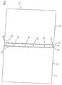
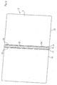
- File 2 comprises a file main unit 4 and a binder for filing tools 6, as shown in Fig. 1 .
- the file main unit 4 and the binder for filing tools 6 are synthetic resin moldings, and integral molding has been performed on the file main unit by extrusion molding or injection molding and on the binder for filing tools by injection molding or the like.
- File main unit 4 comprises a vertically long rectangular back cover part 8 and a pair of vertically long rectangular front cover parts 10 and 12 which are connected with the back cover part 8 in between, on both sides of its long side. As shown in Fig.
- a first hinge 14 which is formed from a V-shaped groove wherein the thickness becomes thin due to the thickness of file main unit 4 is formed on the border of the back cover part 8 and the front cover parts 10 and 12, and the front cover parts 10 and 12 can be folded easily, due to this first hinge 14, from the back cover part 8 or, in other words, can be opened and closed.
- a second hinge 16 of the same cross-sectional V-shape is formed a predetermine distance from and parallel to the first hinge 14, and each front cover part 10 and 12 can be folded due to this second hinge 16.
- a plurality of back hole parts 18 are provided in one row in the long side direction in the center part of the short side direction of the back cover part 8. The back hole parts 18 are aligned with a predetermined distance therebetween.
- the binder for filing tools 6 comprises a flexible locking bar 20 which can be locked in a plurality of flexible places and a band-shaped back board 22 comprising a plurality of engaged parts.
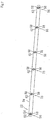
- the entire length of the flexible locking bar 20 is almost the same length as the long side of back cover part 8, as shown in Fig. 3 to Fig. 6 , has a flat grasping part 24 on one edge part and a locking edge part 26 on the other edge.
- a plurality of tying parts 28 and pressure parts 30 are aligned between the grasping part 24 and the locking edge part 26 of the flexible locking bar 20 such as to be alternately interlocked.
- This tying part 28 is provided in a position corresponding to the back hole part 18 in the back cover part 8.
- tying part 28 In the tying part 28, locking part 32 onto which the joining groove is carved in the long axis direction and a circular part 34 which is formed from a curved surface are interlocked.
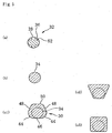
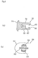
- Fig. 5(a) which is an A-A cross-sectional diagram of Fig. 3
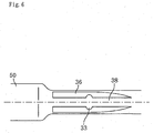
- joining grooves 36 are carved in the four corners and the circular front surfaces 38 and joining grooves 36 are aligned alternately in the circumferential direction.
- joining grooves 36 are carved almost to the center of the typing part 28 and one side which is the pressure part 30 side is carved into a wide-shape and, in contrast, in the circular part 34 side, adjacent joining grooves 36 are carved into narrow tip-shape wile adjacent ( Fig. 6 ).
- joining grooves 36 can be carved at a right-angle to the joining groove bottom part 52, it is preferable to strengthen the engagement by carving into an acute angle and matching with the angle of the key part 60 of the engaging band-shaped back board.
- the circular part 34 has no cuts whatsoever, and is formed from a smooth circular surface, as shown in the B-B cross-sectional view in Fig. 5(b) .
- the locking part 32 has the same radius as the circular part 34 or the radius of the locking part 32 is smaller than the radius of the circular part 34.
- Fig. 5 an example with the same radii is shown.
- the locking part 32 and the circular part 34 are placed on the same axis.
- the pressure part 30 has a first bottom surface 46 which is connected to two R surfaces 44 having a predetermined R on both long sides, respectively, and a second bottom surface 50 which is connected to two taper surfaces 48, connected to R surfaces 44, on both long sides, respectively, and provided such as to be parallel with the first bottom surface 46, as shown in the C - C cross-sectional view in Fig. 5 (c1).
- the shape of the cross-section is not limited to Fig.
- the center axes of the first bottom surface, the second bottom surface, and the pressure part 30 are not on the same axis as the center axis of the connected tying part 28, and the center axis of the tying part 28 is connected such as to shift towards the first bottom surface 46 to the degree that the outer circumference of the tying part 28 contacts the first bottom surface.46 (eccentric structure) (refer to Figs. 5(c2) and (c3)).
- a non-slip protruding part 33 is formed to protrude from the center thereof. This slip stopper is to prevent side to side movement by locking the key part 60 of the key-shaped locking part 56 with the flexible locking bar 20 when locking the flexible locking bar 20.
- Non slip protruding part 33 can be provided on all tying parts 28 or can be provided only on about two central tying parts 28.
- an attaching concave part 35 is carved vertically in the long side direction of the flexible locking bar 20 on the center pressure part 30 out of a plurality of pressure parts 30. When sliding the flexible locking bar 20 by this attaching concave part 35, sliding can be facilitated by using coins or the like.
- a plurality of key-shaped locking parts 56 are erected on the bottom board part 54, in every position corresponding to the tying part 28 and the back hole part 18, as shown in Fig. 7 to Fig. 9 .
- this key-shaped locking part 56 two pinching boards 58 are erected on the bottom board part 54 side by side in the short side direction of the bottom board part 54 such as to oppose with other.
- Key parts 60 are formed to protrude perpendicularly on the upper edge side parts of the pinching boards 58, and the key parts 60 of both pinching boards 58 protrude such as to face inwards, towards each other.
- the diameter of the bottom surface of the key-shaped locking part 56 which is a portion including the pinching board 58 and the stopper part 62, is set to be smaller than the diameter of the back hole part 18, and the key-shaped locking part 56 is designed such as to enable insertion to the back hole part 18.
- the diameter of the bottom surface is the diameter of the smallest circle in contact with the shape joined to the pinching board 58 and the bottom board part 54 of the stopper part 62.
- a front cover locking notch part 61 for locking the front cover part to one side of the engagement portion of the stopper part 62 and the bottom board part 54 is provided.
- Sheet 64 which is inserted into this file, comprises one each of a vertically long rectangular center part 66 and a pouch part 68 wherein two vertically long rectangular sheets connected to both sides of the long sides of the center part 66, which is sandwiched therebetween, are welded excluding one side.
- This center part 66 is welded and sheet hole parts 70 which are aligned in the center with the same distance in between as the tying parts 28 or, in other words, the same distance in between as the back hole parts 18 are provided.
- a sheet notch part 71 for verifying the top and bottom of sheet 64 is provided on the lowermost part of the center part 66 of sheet 64.
- This pouch part is formed from transparent film for inserting papers and the like ( Fig. 14 ).
- a key-shaped locking part 56 which is provided in the band-shaped back board 22, is inserted into the back hole part 18 provided in the back cover part 8 of the file main unit 4. Furthermore, the key-shaped locking part 56 is inserted into the sheet hole part 70 of sheet 64, inserted into this file 2. In this way, file main unit 4 and sheet 64 are held to the key-shaped locking part 56.
- the flexible locking bar 20 is arranged on the band-shaped back board 22 such that each circular part 34 corresponds to each protruding key-shaped locking part 56. Then, by pressing every circular part 34, the circular parts 34 are sandwiched within the key-shaped locking part 56. At this time, the circular part 34 comes in to contact with the stopper part 62 and stops ( Fig, 13(b) ).
- An example wherein the diameter of the circular part 34 is smaller than the diameter of the locking part 32 is shown ( Figs. 13(b) and (c) ), and the key-shaped locking part 56 can be attached and removed with more ease if the diameter of the circular part 34 is small.
- the position of the key part 60 moves from the circular part 34 to the locking part 32 by pressing the grasping part 24 of the flexible locking bar 20 in the horizontal direction and sliding the flexible locking bar 20 in the axis direction. At this time, the key part 60 is interlocked by the joining groove 36. This state is the state shown in Fig. 13(a) .
- the position of the key part 60 moves from the locking part 32 to the circular part 34 by pulling the grasping part 24 of the flexible locking bar 20 in a horizontal direction and sliding the flexible locking bar 20 in the axis direction ( Fig. 11 ).
- a large number of sheets 64 can be held if the first bottom surface 46 of the pressure part 30 is placed on the lower surface such as to press the sheets 64.
- the distance of the rotation center and the first bottom surface 46 is short by making the first bottom surface 46 the lower part and the pressure part 30 can hold the sheets 64 effectively including R surface 44 because both sides of the first bottom surface 46 is R surface 44.
- the number of sheets 64 is a few, a few numbers of sheets 64 can be held if the second bottom surface 50 of the pressure part 30 is placed on the lower surface such as to press the sheets 64.
- the distance of the rotation center and the second bottom surface 50 becomes long and the pressure part can hold the sheets 64 effectively.
- the position of the key part 60 moves from the locking part 32 to the circular part 34 by pressing the locking edge part 26 of the flexibly locking bar 20 in the horizontal direction and sliding the flexible locking bar 20 in the axis direction. If the grasping part 24 is pulled up in this state, each circular part 34 of the flexible locking bar 20 is easily released from each key-shaped locking part 56, in sequential order from the edge part ( Fig. 12 and Fig. 13C ). After all circular parts 34 are released by this method, the object removal and attachment of sheets 64 become possible.
- the removal and attachment of sheets can be facilitated.
- the sheets 64 are held by a plurality of key-shaped locking parts 56, dispersion of sheets 64 due to the detachment of the binder for filing tools 6 does not occur.
- Sheets 64 can be held by the center axis of the circular part 34 shifting the center axis of the pressure part 30, regardless of the amount of sheets 64. In addition, sheets 64 can be held without fail and, on the other hand, removal and attachment is facilitated as well by combining the flexible locking bar 20 and the band-shaped back board 22.
- file 2 there are few components comprising file 2, the flexible locking bar 20, the band-shaped back board 22 and the file main unit 4, component costs and manufacturing costs can be reduced. Furthermore, because the structure is simple, not only are the manufacturing procedures for structural elements reduced, but malfunctions and breakage during use can also be reduced.
- the present invention is not limited to the foregoing embodiment, and modifications and improvements within the range of achieving the object of the present invention are included in the present invention.
- the band-shaped back board 22 and the file main unit 4 are separate constructions in the foregoing example, it is not limited thereto.
- the key-shaped locking part 56 can be erected in the file main unit 4, beforehand, and integrated. Either construction can be used as long as the flexible locking bar 20 can be locked without fail.
- the present embodiment is preferable.
- a file main unit 80 which is an example wherein two pairs of binder parts are provided, is shown.
- Two rows of back hole parts 84 are provided on the back cover part 82 in parallel to the long side direction of the back cover part 82, and the front cover part 88 and back cover part 82 are constructed such as to bend on a single hinge 83.
- Fig. 16 an entire view of the file when two pairs of sheets 86 are bound to the front cover part 88 is shown.
- the cross-section of the pressure part 30 is a shape comprising two flat surfaces, it can be constructed such that one is an R surface or pressing method can be adjusted by the number of sheets by further increasing the number of flat surfaces to three surfaces or four surfaces.
- the lock can be changed to a firm hold with the protrusion angle and the carving angle of the key part 60 and joining grooves 36 as steep slopes.
- synthetic resin which comprises the present invention is not particularly limited as long as the file can be formed.
- polyolefin resin such as polypropylene, propylene-ethylene random copolymer, propylene-ethylene block copolymer and polyethylene
- filling material such as talc and calcium carbonate, coloring agent such as titanium oxide, and other stabilizers and nucleating agents can be added to each of these resins.
Landscapes
- Engineering & Computer Science (AREA)
- Textile Engineering (AREA)
- Sheet Holders (AREA)
Claims (9)
- Bindemappe, mit einer Mehrzahl von Bögen zur Ablage von Material, die die Bögen bindet (64, 86, 124, 216, 250), die eine Mehrzahl von Im Zentrum ausgerichteten Bogenlochelementen (70) aufweisen, mit zwei vorderen Abdeckelementen (10, 12), einer Arretierleiste (20), einer bandförmigen hinteren Platte (22) und einem hinteren Abdeckeiement (8, 82), wobei
zwei vordere Abdeckelemente (10, 12), die aus flachen Platten gebildet sind, mit dem hinteren Abdeckelement (8, 82) mit jeweils einer Seite eines jeden der beiden vorderen Abdeckelemente (10, 12) verbunden sind, um zu einer vorderen Abdeckung kombiniert zu werden, und wobei
die bandförmige hintere Platte (22), die kürzer als das hintere Abdeckelement (B, 82) ist, das auf der vorderen Seite der vorderen Abdeckung bereitgestellt ist, dazu ausgestaltet ist, in die Arretierleiste (20) eingelegt zu werden, und wobei
eine Mehrzahl von hinteren Lochelementen (18) in dem hinteren Abdeckelemente (8, 82) vorgesehen ist, wobei die bandförmige hintere Platte (22) eine Mehrzahl von passfederförmigen Arretierelementen (56) aufweist, die auf der vorderen Oberfläche davon aufgerichtet sind, wobei jedes passfederförmige Arretierelement (56) jedes der Mehrzahl von hinteren Lochelementen (18) durchdringt, die auf dem hinteren Abdeckelement (8, 82) vorgesehen sind, wobei die passfederförmigen Arretierelemente (56) auch die Bogenlochelemente (70) des Bogens (64, 86, 124, 216, 250) durchdringen, wobei eine Mehrzahl von Bindeelementen (28) in der Arretierleiste (20) an der Position vorgesehen ist, die den Positionen der passfederförmigen Arretierelemente (56) entspricht, und wobei die Bögen (64, 86, 124, 216, 250) zwischen der Arretierleiste (20) und der vorderen Abdeckung durch Arretieren eines jeden Bindeelements (28) mit dem entsprechenden passfederförmigen Arretierelement (56) mithilfe eines Abstandseinstellungsmittels gehalten werden, so dass die Bögen (64, 86, 124, 216, 250) geeignet gehalten werden, abhängig von der Anzahl der Bögen, dadurch gekennzeichnet, dass
die Arretierleiste (20) ein Bindeelement (28) aufweist, das einen kleinen Durchmesser aufweist, und ein Druckelement (30), das einen größeren Durchmesser als das Bindeelement (28) aufweist, wobei
das Bindeelement (28) ein Arretierelement (32), in welches eine verbindende Nut (36) in der langen Achsenrichtung eingeritzt ist, und ein kreisrundes Element (34) aufweist, das aus einer gekrümmten Oberfläche gebildet ist. - Bindemappe zur Ablage von Material nach Anspruch 1, wobei ein konkaves Befestigungselement (35) in der Arretierleiste (20) ins Zentrum der Arretierleiste (20) geritzt ist, um eine dünne Platte zur Ermöglichung einer horizontalen Bewegung einzufügen.
- Bindemappe zur Ablage von Material nach Anspruch 1, wobei die verbindende Nut (36) an vier symmetrischen Punkten der gekrümmten Oberfläche eingekerbt ist.
- Bindemappe zur Ablage von Material nach Anspruch 1, wobei die zentrale Achslinie des Bindeelements (28) in dem Druckelement (30) mit einer Neigung in eine bestimmte Richtung von der zentralen Achse des Druckelements (30) vorgesehen ist.
- Bindemappe zur Ablage von Material nach Anspruch 1, wobei Passfederelemente (60) in dem passfederförmigen Arretierelement (56), die auf der Spitze des klemmenden Elements vorgesehen sind, um die Arretierleiste (20) dazwischen einzuklemmen, beide nach innen vorspringen.
- Bindemappe zur Ablage von Material nach Anspruch 1, wobei ein schlupffreies vospringendes Element in dem Arretierelement (20), das in das Bindeelement (28) eingeritzt ist, so ausgebildet ist, dass es von dem Zentrum des Arretierelements (20) zum Arretieren des Passfederelements (60) vorspringt.
- Bindemappe zur Ablage von Material nach Anspruch 1, wobei ein plattenförmiges Anschlagselement (62), dessen Höhe geringer ist als die klemmenden Elemente in dem passfederförmigen Arretierelement (56), zwischen den gegenüberliegenden Klemmelementen gebildet ist, um senkrecht zum hinteren Abdeckelement (8, 82) vorzuspringen.
- Bindemappe zur Ablage von Material nach einem der Ansprüche 1 bis 7, wobei eine verbindende Nut (36) und ein unterer Teil (52) der verbindenden Nut der Arretierleiste (20) in einem spitzen Winkel gemäß dem passfederförmigen Arretierelement (56) einer ineinandergreifenden bandförmigen hinteren Platte (22) eingeritzt sind.
- Bindemappe zur Ablage von Material nach Anspruch 1, wobei die Arretierleiste (20) aus einer flexiblen Arretierleiste, die flexibel ist, zusammengesetzt ist.
Applications Claiming Priority (2)
| Application Number | Priority Date | Filing Date | Title |
|---|---|---|---|
| PCT/JP2003/005541 WO2004096576A1 (ja) | 2003-04-30 | 2003-04-30 | ファイリング用具用綴具 |
| PCT/JP2004/004678 WO2004096575A1 (ja) | 2003-04-30 | 2004-03-31 | ファイリング用具用綴具 |
Publications (3)
| Publication Number | Publication Date |
|---|---|
| EP1634723A1 EP1634723A1 (de) | 2006-03-15 |
| EP1634723A4 EP1634723A4 (de) | 2011-08-10 |
| EP1634723B1 true EP1634723B1 (de) | 2016-02-03 |
Family
ID=33398144
Family Applications (1)
| Application Number | Title | Priority Date | Filing Date |
|---|---|---|---|
| EP04724801.8A Expired - Lifetime EP1634723B1 (de) | 2003-04-30 | 2004-03-31 | Bindevorrichtung für ablagewerkzeug |
Country Status (7)
| Country | Link |
|---|---|
| US (1) | US7575388B2 (de) |
| EP (1) | EP1634723B1 (de) |
| JP (1) | JP4531695B2 (de) |
| KR (1) | KR101060485B1 (de) |
| CN (1) | CN100421968C (de) |
| IL (1) | IL170775A (de) |
| WO (2) | WO2004096576A1 (de) |
Families Citing this family (5)
| Publication number | Priority date | Publication date | Assignee | Title |
|---|---|---|---|---|
| US7798736B2 (en) * | 2006-07-21 | 2010-09-21 | Hewlett-Packard Development Company, L.P. | Media binder arrangements |
| JP5374721B2 (ja) * | 2010-04-12 | 2013-12-25 | コクヨ株式会社 | ノート |
| CN103221227B (zh) * | 2010-11-17 | 2016-03-02 | 国誉株式会社 | 装订用具 |
| GB2526124B (en) * | 2014-05-14 | 2020-09-02 | Tung Hing Plastic Manufactory Ltd | Hair fastener |
| JP6939275B2 (ja) * | 2017-09-01 | 2021-09-22 | コクヨ株式会社 | ファイル |
Family Cites Families (33)
| Publication number | Priority date | Publication date | Assignee | Title |
|---|---|---|---|---|
| US828974A (en) * | 1905-09-07 | 1906-08-21 | Georg Eduard Schmidmer | File for papers and documents. |
| US2727550A (en) | 1952-12-06 | 1955-12-20 | Buxton Inc | Pass case with removable envelopes |
| GB1200592A (en) * | 1966-06-02 | 1970-07-29 | William Charles Markham | Filing devices |
| US3647306A (en) * | 1970-03-04 | 1972-03-07 | John H Chamberlin | Binding post construction |
| JPS5037616U (de) * | 1973-08-03 | 1975-04-19 | ||
| JPS519823U (de) * | 1974-07-09 | 1976-01-24 | ||
| US4121892A (en) * | 1976-10-08 | 1978-10-24 | Per Sigurd Nes | Holder for loose filing sheets |
| JPS5529570Y2 (de) * | 1976-11-05 | 1980-07-14 | ||
| JPS5376031U (de) * | 1976-11-27 | 1978-06-24 | Takeshi Kumagai | |
| GB1511198A (en) | 1976-12-17 | 1978-05-17 | Xerox Corp | Electrographic imaging apparatus |
| JPS567668Y2 (de) | 1977-05-02 | 1981-02-19 | ||
| JPS54151420U (de) * | 1978-04-12 | 1979-10-22 | ||
| JPS5939821B2 (ja) * | 1978-05-19 | 1984-09-26 | 松下電器産業株式会社 | 磁気記録再生装置 |
| FR2455517A1 (fr) * | 1979-05-02 | 1980-11-28 | Degraeve Pierre | Nouveaux perfectionnements aux procedes de reliures mobiles ou demontables |
| GB2065555A (en) | 1979-12-06 | 1981-07-01 | Aquazar Electronics Ltd | Document binder |
| JPS5987978U (ja) * | 1982-12-03 | 1984-06-14 | 三菱鉛筆株式会社 | フアイル |
| FR2558416A1 (fr) | 1984-01-19 | 1985-07-26 | Carpentier Francoise | Perfectionnement a la reliure demontable d'un document a feuillets mobiles |
| JPS60192696A (ja) | 1984-03-14 | 1985-10-01 | リヒト産業株式会社 | フアイル |
| FR2611593A2 (fr) | 1984-07-26 | 1988-09-09 | Carpentier Francoise | Reliure inviolable d'un document a feuilles mobiles, doubles ou simples |
| DE3600557A1 (de) | 1986-01-10 | 1987-07-16 | Brueckner Apparatebau Gmbh | Verfahren und vorrichtung zum waschen von auf einen perforierten baum gewickelter ware |
| US4730972A (en) * | 1986-03-14 | 1988-03-15 | Taurus Holdings, Inc. | Book binding method, paper sheets binder and adjustable spine |
| JPS62162070U (de) * | 1986-04-02 | 1987-10-15 | ||
| JPH0391444U (de) * | 1989-12-28 | 1991-09-18 | ||
| US5690443A (en) | 1995-06-05 | 1997-11-25 | Sullivan; Thomas V. | Adjustable, releasable binding fastener |
| CN2308509Y (zh) * | 1997-05-27 | 1999-02-24 | 陈永村 | 内页之固定结构 |
| US6086106A (en) * | 1998-09-18 | 2000-07-11 | Avery Dennison Corporation | Double vision cover and binder assembly |
| JP2000229493A (ja) * | 1999-02-09 | 2000-08-22 | Ono Hoso:Kk | ファイル綴じ具 |
| JP2002192872A (ja) * | 2000-10-19 | 2002-07-10 | Tomoda Giken Kogyo Kk | ファイリング用具 |
| JP3602815B2 (ja) * | 2001-09-21 | 2004-12-15 | 株式会社リヒトラブ | 綴じ具 |
| US6578240B2 (en) * | 2001-11-09 | 2003-06-17 | John Fortenberry | Paper binding fastener |
| JP3091444U (ja) * | 2002-07-15 | 2003-01-31 | 株式会社ファイル | ファイル |
| JP3670264B2 (ja) * | 2002-12-25 | 2005-07-13 | 株式会社リヒトラブ | 綴り具 |
| JP2004209677A (ja) * | 2002-12-27 | 2004-07-29 | Hiroyuki Kawai | ファイリング用書類保持具 |
-
2003
- 2003-04-30 WO PCT/JP2003/005541 patent/WO2004096576A1/ja not_active Ceased
-
2004
- 2004-03-31 EP EP04724801.8A patent/EP1634723B1/de not_active Expired - Lifetime
- 2004-03-31 KR KR1020057020121A patent/KR101060485B1/ko not_active Expired - Fee Related
- 2004-03-31 WO PCT/JP2004/004678 patent/WO2004096575A1/ja not_active Ceased
- 2004-03-31 JP JP2005505829A patent/JP4531695B2/ja not_active Expired - Lifetime
- 2004-03-31 US US10/550,296 patent/US7575388B2/en not_active Expired - Lifetime
- 2004-03-31 CN CNB2004800114806A patent/CN100421968C/zh not_active Expired - Fee Related
-
2005
- 2005-09-08 IL IL170775A patent/IL170775A/en active IP Right Grant
Also Published As
| Publication number | Publication date |
|---|---|
| KR101060485B1 (ko) | 2011-08-31 |
| JP4531695B2 (ja) | 2010-08-25 |
| KR20060012273A (ko) | 2006-02-07 |
| HK1085979A1 (zh) | 2006-09-08 |
| EP1634723A1 (de) | 2006-03-15 |
| IL170775A (en) | 2010-06-30 |
| CN1780739A (zh) | 2006-05-31 |
| CN100421968C (zh) | 2008-10-01 |
| WO2004096575A1 (ja) | 2004-11-11 |
| JPWO2004096575A1 (ja) | 2006-07-13 |
| EP1634723A4 (de) | 2011-08-10 |
| US7575388B2 (en) | 2009-08-18 |
| US20060204320A1 (en) | 2006-09-14 |
| WO2004096576A1 (ja) | 2004-11-11 |
Similar Documents
| Publication | Publication Date | Title |
|---|---|---|
| US7159730B2 (en) | Folding crate with array connection features | |
| US3970331A (en) | Binder element | |
| US6270280B1 (en) | Spine binder | |
| KR940005910B1 (ko) | 책자결속방법 및 바인다 | |
| EP1642630B1 (de) | Konstruktionsstein | |
| US9556000B2 (en) | Reel assembly | |
| US20010051069A1 (en) | Storage device | |
| US4976567A (en) | Connector for corrugated materials | |
| US7575388B2 (en) | Binder for filing tool | |
| US7708487B2 (en) | Binder spine | |
| JP3946209B2 (ja) | 結合具およびこれを用いた組立式コンテナ | |
| JPH07237383A (ja) | ファイル | |
| KR101481735B1 (ko) | 차대번호 커버 | |
| US5626432A (en) | Adjustable locking binder | |
| US20050013653A1 (en) | Self-closing ring binder | |
| JPH06298245A (ja) | 折りたたみ可能な箱 | |
| HK1085979B (en) | Binder for filing tool | |
| US2388572A (en) | Interlocking clip | |
| JPH062503B2 (ja) | 組立て箱 | |
| CN214398026U (zh) | 一种自带防私拆封签的锁扣 | |
| CA2125640A1 (en) | Sheet fastener hinge device | |
| GB2199885A (en) | Improvements in or relating to fastening devices | |
| JPH0615460Y2 (ja) | ケーブル線結束用係止具 | |
| JP3727405B2 (ja) | 増設可能な帳票綴具 | |
| JP2025120064A (ja) | ファイル |
Legal Events
| Date | Code | Title | Description |
|---|---|---|---|
| PUAI | Public reference made under article 153(3) epc to a published international application that has entered the european phase |
Free format text: ORIGINAL CODE: 0009012 |
|
| 17P | Request for examination filed |
Effective date: 20051004 |
|
| AK | Designated contracting states |
Kind code of ref document: A1 Designated state(s): AT BE BG CH CY CZ DE DK EE ES FI FR GB GR HU IE IT LI LU MC NL PL PT RO SE SI SK TR |
|
| DAX | Request for extension of the european patent (deleted) | ||
| RIC1 | Information provided on ipc code assigned before grant |
Ipc: B42F 13/00 20060101AFI20110630BHEP |
|
| A4 | Supplementary search report drawn up and despatched |
Effective date: 20110707 |
|
| 17Q | First examination report despatched |
Effective date: 20120203 |
|
| REG | Reference to a national code |
Ref country code: DE Ref legal event code: R079 Ref document number: 602004048598 Country of ref document: DE Free format text: PREVIOUS MAIN CLASS: B42F0013000000 Ipc: B42B0005080000 |
|
| GRAP | Despatch of communication of intention to grant a patent |
Free format text: ORIGINAL CODE: EPIDOSNIGR1 |
|
| RIC1 | Information provided on ipc code assigned before grant |
Ipc: B42B 5/08 20060101AFI20150826BHEP Ipc: B42F 13/14 20060101ALI20150826BHEP |
|
| INTG | Intention to grant announced |
Effective date: 20150922 |
|
| GRAS | Grant fee paid |
Free format text: ORIGINAL CODE: EPIDOSNIGR3 |
|
| GRAA | (expected) grant |
Free format text: ORIGINAL CODE: 0009210 |
|
| AK | Designated contracting states |
Kind code of ref document: B1 Designated state(s): AT BE BG CH CY CZ DE DK EE ES FI FR GB GR HU IE IT LI LU MC NL PL PT RO SE SI SK TR |
|
| REG | Reference to a national code |
Ref country code: GB Ref legal event code: FG4D |
|
| REG | Reference to a national code |
Ref country code: AT Ref legal event code: REF Ref document number: 773479 Country of ref document: AT Kind code of ref document: T Effective date: 20160215 Ref country code: CH Ref legal event code: EP |
|
| REG | Reference to a national code |
Ref country code: IE Ref legal event code: FG4D |
|
| REG | Reference to a national code |
Ref country code: CH Ref legal event code: NV Representative=s name: KELLER AND PARTNER PATENTANWAELTE AG, CH |
|
| REG | Reference to a national code |
Ref country code: DE Ref legal event code: R096 Ref document number: 602004048598 Country of ref document: DE |
|
| REG | Reference to a national code |
Ref country code: FR Ref legal event code: PLFP Year of fee payment: 13 |
|
| PGFP | Annual fee paid to national office [announced via postgrant information from national office to epo] |
Ref country code: LU Payment date: 20160325 Year of fee payment: 13 Ref country code: CH Payment date: 20160324 Year of fee payment: 13 |
|
| REG | Reference to a national code |
Ref country code: SE Ref legal event code: TRGR |
|
| PGFP | Annual fee paid to national office [announced via postgrant information from national office to epo] |
Ref country code: FI Payment date: 20160324 Year of fee payment: 13 |
|
| REG | Reference to a national code |
Ref country code: NL Ref legal event code: MP Effective date: 20160203 |
|
| REG | Reference to a national code |
Ref country code: AT Ref legal event code: MK05 Ref document number: 773479 Country of ref document: AT Kind code of ref document: T Effective date: 20160203 |
|
| PG25 | Lapsed in a contracting state [announced via postgrant information from national office to epo] |
Ref country code: GR Free format text: LAPSE BECAUSE OF FAILURE TO SUBMIT A TRANSLATION OF THE DESCRIPTION OR TO PAY THE FEE WITHIN THE PRESCRIBED TIME-LIMIT Effective date: 20160504 Ref country code: ES Free format text: LAPSE BECAUSE OF FAILURE TO SUBMIT A TRANSLATION OF THE DESCRIPTION OR TO PAY THE FEE WITHIN THE PRESCRIBED TIME-LIMIT Effective date: 20160203 Ref country code: IT Free format text: LAPSE BECAUSE OF FAILURE TO SUBMIT A TRANSLATION OF THE DESCRIPTION OR TO PAY THE FEE WITHIN THE PRESCRIBED TIME-LIMIT Effective date: 20160203 |
|
| PG25 | Lapsed in a contracting state [announced via postgrant information from national office to epo] |
Ref country code: PT Free format text: LAPSE BECAUSE OF FAILURE TO SUBMIT A TRANSLATION OF THE DESCRIPTION OR TO PAY THE FEE WITHIN THE PRESCRIBED TIME-LIMIT Effective date: 20160603 Ref country code: BE Free format text: LAPSE BECAUSE OF NON-PAYMENT OF DUE FEES Effective date: 20160331 Ref country code: PL Free format text: LAPSE BECAUSE OF FAILURE TO SUBMIT A TRANSLATION OF THE DESCRIPTION OR TO PAY THE FEE WITHIN THE PRESCRIBED TIME-LIMIT Effective date: 20160203 Ref country code: AT Free format text: LAPSE BECAUSE OF FAILURE TO SUBMIT A TRANSLATION OF THE DESCRIPTION OR TO PAY THE FEE WITHIN THE PRESCRIBED TIME-LIMIT Effective date: 20160203 Ref country code: NL Free format text: LAPSE BECAUSE OF FAILURE TO SUBMIT A TRANSLATION OF THE DESCRIPTION OR TO PAY THE FEE WITHIN THE PRESCRIBED TIME-LIMIT Effective date: 20160203 |
|
| PG25 | Lapsed in a contracting state [announced via postgrant information from national office to epo] |
Ref country code: DK Free format text: LAPSE BECAUSE OF FAILURE TO SUBMIT A TRANSLATION OF THE DESCRIPTION OR TO PAY THE FEE WITHIN THE PRESCRIBED TIME-LIMIT Effective date: 20160203 Ref country code: EE Free format text: LAPSE BECAUSE OF FAILURE TO SUBMIT A TRANSLATION OF THE DESCRIPTION OR TO PAY THE FEE WITHIN THE PRESCRIBED TIME-LIMIT Effective date: 20160203 |
|
| REG | Reference to a national code |
Ref country code: DE Ref legal event code: R097 Ref document number: 602004048598 Country of ref document: DE |
|
| PG25 | Lapsed in a contracting state [announced via postgrant information from national office to epo] |
Ref country code: CZ Free format text: LAPSE BECAUSE OF FAILURE TO SUBMIT A TRANSLATION OF THE DESCRIPTION OR TO PAY THE FEE WITHIN THE PRESCRIBED TIME-LIMIT Effective date: 20160203 Ref country code: SK Free format text: LAPSE BECAUSE OF FAILURE TO SUBMIT A TRANSLATION OF THE DESCRIPTION OR TO PAY THE FEE WITHIN THE PRESCRIBED TIME-LIMIT Effective date: 20160203 Ref country code: RO Free format text: LAPSE BECAUSE OF FAILURE TO SUBMIT A TRANSLATION OF THE DESCRIPTION OR TO PAY THE FEE WITHIN THE PRESCRIBED TIME-LIMIT Effective date: 20160203 |
|
| PLBE | No opposition filed within time limit |
Free format text: ORIGINAL CODE: 0009261 |
|
| STAA | Information on the status of an ep patent application or granted ep patent |
Free format text: STATUS: NO OPPOSITION FILED WITHIN TIME LIMIT |
|
| REG | Reference to a national code |
Ref country code: IE Ref legal event code: MM4A |
|
| PG25 | Lapsed in a contracting state [announced via postgrant information from national office to epo] |
Ref country code: BE Free format text: LAPSE BECAUSE OF FAILURE TO SUBMIT A TRANSLATION OF THE DESCRIPTION OR TO PAY THE FEE WITHIN THE PRESCRIBED TIME-LIMIT Effective date: 20160203 |
|
| 26N | No opposition filed |
Effective date: 20161104 |
|
| PG25 | Lapsed in a contracting state [announced via postgrant information from national office to epo] |
Ref country code: IE Free format text: LAPSE BECAUSE OF NON-PAYMENT OF DUE FEES Effective date: 20160331 |
|
| REG | Reference to a national code |
Ref country code: FR Ref legal event code: PLFP Year of fee payment: 14 |
|
| PG25 | Lapsed in a contracting state [announced via postgrant information from national office to epo] |
Ref country code: BG Free format text: LAPSE BECAUSE OF FAILURE TO SUBMIT A TRANSLATION OF THE DESCRIPTION OR TO PAY THE FEE WITHIN THE PRESCRIBED TIME-LIMIT Effective date: 20160503 Ref country code: SI Free format text: LAPSE BECAUSE OF FAILURE TO SUBMIT A TRANSLATION OF THE DESCRIPTION OR TO PAY THE FEE WITHIN THE PRESCRIBED TIME-LIMIT Effective date: 20160203 |
|
| PGFP | Annual fee paid to national office [announced via postgrant information from national office to epo] |
Ref country code: FR Payment date: 20170213 Year of fee payment: 14 |
|
| PGFP | Annual fee paid to national office [announced via postgrant information from national office to epo] |
Ref country code: GB Payment date: 20170329 Year of fee payment: 14 |
|
| PGFP | Annual fee paid to national office [announced via postgrant information from national office to epo] |
Ref country code: SE Payment date: 20160329 Year of fee payment: 13 |
|
| PGFP | Annual fee paid to national office [announced via postgrant information from national office to epo] |
Ref country code: DE Payment date: 20170329 Year of fee payment: 14 |
|
| PG25 | Lapsed in a contracting state [announced via postgrant information from national office to epo] |
Ref country code: FI Free format text: LAPSE BECAUSE OF NON-PAYMENT OF DUE FEES Effective date: 20170331 |
|
| REG | Reference to a national code |
Ref country code: CH Ref legal event code: PL |
|
| PG25 | Lapsed in a contracting state [announced via postgrant information from national office to epo] |
Ref country code: LU Free format text: LAPSE BECAUSE OF NON-PAYMENT OF DUE FEES Effective date: 20170331 |
|
| PG25 | Lapsed in a contracting state [announced via postgrant information from national office to epo] |
Ref country code: LI Free format text: LAPSE BECAUSE OF NON-PAYMENT OF DUE FEES Effective date: 20170331 Ref country code: CH Free format text: LAPSE BECAUSE OF NON-PAYMENT OF DUE FEES Effective date: 20170331 Ref country code: SE Free format text: LAPSE BECAUSE OF NON-PAYMENT OF DUE FEES Effective date: 20170401 |
|
| PG25 | Lapsed in a contracting state [announced via postgrant information from national office to epo] |
Ref country code: HU Free format text: LAPSE BECAUSE OF FAILURE TO SUBMIT A TRANSLATION OF THE DESCRIPTION OR TO PAY THE FEE WITHIN THE PRESCRIBED TIME-LIMIT; INVALID AB INITIO Effective date: 20040331 Ref country code: CY Free format text: LAPSE BECAUSE OF FAILURE TO SUBMIT A TRANSLATION OF THE DESCRIPTION OR TO PAY THE FEE WITHIN THE PRESCRIBED TIME-LIMIT Effective date: 20160203 |
|
| PG25 | Lapsed in a contracting state [announced via postgrant information from national office to epo] |
Ref country code: TR Free format text: LAPSE BECAUSE OF FAILURE TO SUBMIT A TRANSLATION OF THE DESCRIPTION OR TO PAY THE FEE WITHIN THE PRESCRIBED TIME-LIMIT Effective date: 20160203 Ref country code: MC Free format text: LAPSE BECAUSE OF FAILURE TO SUBMIT A TRANSLATION OF THE DESCRIPTION OR TO PAY THE FEE WITHIN THE PRESCRIBED TIME-LIMIT Effective date: 20160203 |
|
| REG | Reference to a national code |
Ref country code: DE Ref legal event code: R119 Ref document number: 602004048598 Country of ref document: DE |
|
| GBPC | Gb: european patent ceased through non-payment of renewal fee |
Effective date: 20180331 |
|
| PG25 | Lapsed in a contracting state [announced via postgrant information from national office to epo] |
Ref country code: DE Free format text: LAPSE BECAUSE OF NON-PAYMENT OF DUE FEES Effective date: 20181002 |
|
| PG25 | Lapsed in a contracting state [announced via postgrant information from national office to epo] |
Ref country code: GB Free format text: LAPSE BECAUSE OF NON-PAYMENT OF DUE FEES Effective date: 20180331 |
|
| PG25 | Lapsed in a contracting state [announced via postgrant information from national office to epo] |
Ref country code: FR Free format text: LAPSE BECAUSE OF NON-PAYMENT OF DUE FEES Effective date: 20180331 |