EP1634516A1 - Sitz mit sitzsensor und sitzkissen - Google Patents
Sitz mit sitzsensor und sitzkissen Download PDFInfo
- Publication number
- EP1634516A1 EP1634516A1 EP04745438A EP04745438A EP1634516A1 EP 1634516 A1 EP1634516 A1 EP 1634516A1 EP 04745438 A EP04745438 A EP 04745438A EP 04745438 A EP04745438 A EP 04745438A EP 1634516 A1 EP1634516 A1 EP 1634516A1
- Authority
- EP
- European Patent Office
- Prior art keywords
- seating sensor
- seat
- pad
- seating
- disposed
- Prior art date
- Legal status (The legal status is an assumption and is not a legal conclusion. Google has not performed a legal analysis and makes no representation as to the accuracy of the status listed.)
- Withdrawn
Links
Images


Classifications
-
- B—PERFORMING OPERATIONS; TRANSPORTING
- B60—VEHICLES IN GENERAL
- B60R—VEHICLES, VEHICLE FITTINGS, OR VEHICLE PARTS, NOT OTHERWISE PROVIDED FOR
- B60R21/00—Arrangements or fittings on vehicles for protecting or preventing injuries to occupants or pedestrians in case of accidents or other traffic risks
- B60R21/01—Electrical circuits for triggering passive safety arrangements, e.g. airbags, safety belt tighteners, in case of vehicle accidents or impending vehicle accidents
- B60R21/015—Electrical circuits for triggering passive safety arrangements, e.g. airbags, safety belt tighteners, in case of vehicle accidents or impending vehicle accidents including means for detecting the presence or position of passengers, passenger seats or child seats, and the related safety parameters therefor, e.g. speed or timing of airbag inflation in relation to occupant position or seat belt use
- B60R21/01512—Passenger detection systems
- B60R21/01516—Passenger detection systems using force or pressure sensing means
-
- B—PERFORMING OPERATIONS; TRANSPORTING
- B60—VEHICLES IN GENERAL
- B60N—SEATS SPECIALLY ADAPTED FOR VEHICLES; VEHICLE PASSENGER ACCOMMODATION NOT OTHERWISE PROVIDED FOR
- B60N2/00—Seats specially adapted for vehicles; Arrangement or mounting of seats in vehicles
- B60N2/002—Seats provided with an occupancy detection means mounted therein or thereon
- B60N2/0021—Seats provided with an occupancy detection means mounted therein or thereon characterised by the type of sensor or measurement
- B60N2/0024—Seats provided with an occupancy detection means mounted therein or thereon characterised by the type of sensor or measurement for identifying, categorising or investigation of the occupant or object on the seat
- B60N2/0025—Seats provided with an occupancy detection means mounted therein or thereon characterised by the type of sensor or measurement for identifying, categorising or investigation of the occupant or object on the seat by using weight measurement
-
- B—PERFORMING OPERATIONS; TRANSPORTING
- B60—VEHICLES IN GENERAL
- B60N—SEATS SPECIALLY ADAPTED FOR VEHICLES; VEHICLE PASSENGER ACCOMMODATION NOT OTHERWISE PROVIDED FOR
- B60N2/00—Seats specially adapted for vehicles; Arrangement or mounting of seats in vehicles
- B60N2/002—Seats provided with an occupancy detection means mounted therein or thereon
- B60N2/0021—Seats provided with an occupancy detection means mounted therein or thereon characterised by the type of sensor or measurement
- B60N2/003—Seats provided with an occupancy detection means mounted therein or thereon characterised by the type of sensor or measurement characterised by the sensor mounting location in or on the seat
- B60N2/0031—Seats provided with an occupancy detection means mounted therein or thereon characterised by the type of sensor or measurement characterised by the sensor mounting location in or on the seat mounted on the frame
-
- B—PERFORMING OPERATIONS; TRANSPORTING
- B60—VEHICLES IN GENERAL
- B60N—SEATS SPECIALLY ADAPTED FOR VEHICLES; VEHICLE PASSENGER ACCOMMODATION NOT OTHERWISE PROVIDED FOR
- B60N2210/00—Sensor types, e.g. for passenger detection systems or for controlling seats
- B60N2210/30—Temperature sensors
-
- B—PERFORMING OPERATIONS; TRANSPORTING
- B60—VEHICLES IN GENERAL
- B60N—SEATS SPECIALLY ADAPTED FOR VEHICLES; VEHICLE PASSENGER ACCOMMODATION NOT OTHERWISE PROVIDED FOR
- B60N2210/00—Sensor types, e.g. for passenger detection systems or for controlling seats
- B60N2210/40—Force or pressure sensors
Definitions
- the present invention relates to a seat with a sheet-like seating sensor for detecting seating of a human body, and more particularly relates to a seat with a seating sensor preferably applied to a seat of a motor vehicle. Further, the present invention relates to a pad for use in the seat with the seating sensor.
- a seating sensor is sometimes provided at an upper face of a seat for detecting whether an occupant is seated in the seat.
- a slab of about 5 mm in thickness is adhered in a manner so as to cover the seating sensor, or a frame laminating process of about 5 mm in thickness is performed as a countermeasure against a foreign body sensation, caused by the presence of a seating sensor when the occupant is seated in the seat.
- a seat with a seating sensor in which a sheet-like seating sensor is disposed inside part of a pad is described, and as one mode, a configuration in which a slit is formed from a side face of the pad toward a center portion threreof and a seating sensor is disposed in the slit, is described. Further, as another mode, a configuration is described, in which a hole is formed from a bottom face of a urethane pad toward an upper part thereof, and a urethane foam insertion member having approximately the same size as that of the hole is inserted into the hole and a seating sensor is disposed at an upper face of the urethane foam insertion member.
- the seating sensor When the slit or the hole is formed in the urethane foam pad, and the seating sensor is disposed in the slit or the hole as described in the Japanese Unexamined Patent Application Publication No. 11-34710, it is required to form the slit or the hole, or to manufacture the insertion member to insert into the hole. In addition, it is also required to insert and fix the seating sensor into the slit, or to fix the insertion member to a main body side of the pad after inserting the insertion member into the hole, both of which result in the increase of the manufacturing man-hours.
- An object of the present invention is to provide a seat with a seating sensor capable of solving various kinds of problems in the conventional technology and that is easy to manufacture, and capable of eliminating a foreign body sensation of the sensor at a time of seating, and a pad for the seat.
- Another object of the present invention is to provide a seat with a seating sensor capable of sensitively detecting seating, and a pad therefor.
- a seat with a seating sensor is characterized in including a soft pad formed of foamed resin, and a sheet-like pressure-sensitive sensor for detecting a human body seated on the pad, in which the pad is integrally molded with the seating sensor by means of a foaming molding process.
- a pad for a seat is characterized in including a soft pad formed of resin foam, and a sheet-like pressure-sensitive sensor for detecting a human body seated on the pad, in which the pad is integrally molded with the seating sensor by means of a foaming molding process.
- the pad is integrally molded with the seating sensor by means of foaming molding process, the seat and the pad are easily manufactured and a manufacturing cost is low.
- a seat with a seating sensor is characterized in including a soft pad formed of resin foam and a sheet-like pressure-sensitive sensor for detecting a human body seated on the pad, in which a rigid plate-like member is disposed at an upper side or a lower side of the seating sensor.
- a pad for a seat is characterized in including a soft pad formed of resin foam, and a sheet-like pressure-sensitive sensor for detecting a human body seated on the pad, in which a rigid plate-like member is disposed at an upper side or a lower side of the seating sensor.
- the rigid plate-shaped member is disposed at a position of at least one of an upper side or a lower side of the seating sensor and thereby, even when the seating sensor is disposed at a bottom face of the pad, a seating load is applied to the seating sensor in a suitable manner and seating is detected in an ensured manner.
- a projection may be formed on the rigid plate-like member so as to apply a load to the seating sensor in a concentrated manner.
- the rigid plate-like member disposed at the lower side of the seating sensor serves as a supporting member disposed at the bottom face of the seat with the seating sensor, and in particular, the supporting member is preferably formed with the pad in an integral manner.
- a wiring cable insertion portion such as an opening, a notch, or the like is provided in the supporting member, and the wiring cable of the seating sensor is led through the wiring cable insertion portion and led outward of the seat with the seating sensor and thereby the seating sensor is easily connected to a control system.
- the pad integrally formed with the seating sensor can be manufactured by disposing the supporting member, the seating sensor, and the rigid plate-like member in an overlapping state along an inside face of the metallic mold for a molding process, and by causing to foam a foaming resin material, such as urethane or the like in the metallic mold, keeping the aforementioned state.
- the wiring cable of the seating sensor is led through the wiring cable insertion portion and thereby the wiring cable is led outward from the wiring cable insertion portion of the supporting member at a bottom face of the pad and the seat with the seating sensor.
- the seat with a seating sensor is characterized in including a soft pad formed of resin foam, and a sheet-like pressure-sensitive sensor for detecting a human body seated on the pad, in which the seating sensor is formed into a separate body from the pad and is disposed at a lower side of the pad.
- the seating sensor in which the seating sensor is formed into the separate body from the pad, the seating sensor can be solely replaced when a fault or a malfunction occurs with the seating sensor. Further, the seat with the seating sensor is manufactured with ease and at low cost.
- the rigid plate-like member may be also disposed at a position of at least one of an upper side and a lower side of the seating sensor, however, the rigid plate-like member may be omitted.
- the seat with the seating sensor and the pad in the present invention are easily manufactured and are also possible to configure such that the foreign body sensation is not felt at all even when seated at an upper face of the pad.
- FIG. 1a is an anteroposterior cross-section illustrating a seat with a seating sensor according to the present invention
- FIG. 1b is a cross-section, taken along the B-B cutting line in FIG. 1a.
- a supporting member 2 is integrally provided at a bottom face of a pad 1.
- the supporting member 2 is formed of non-woven cloth, coarse wool felt, or the like.
- the pad 1 is formed of urethane foam in this embodiment.
- the upper face and four side faces of the pad 1 are covered with a cover (cover trim) 3 formed of cloth, leather, or the like.
- a sheet-like seating sensor 4 and a plate 5 serving as a rigid plate-like member that covers the seating sensor 4 are disposed between a bottom face of the pad 1 and the supporting member 2.
- the seating sensor 4 is formed of a pressure-sensitive sensor for generating a turning-ON signal, when the pressure-sensitive sensor receives pressure greater than a predetermined value, or a deformation.
- the plate 5 is formed of pressed felt that is a kind of felt whose rigidity is increased by being pressed, a synthetic resin plate formed of an acrylic material, polypropylene or the like, a metal plate formed of iron or the like, or rigid cloth provided with rigidity caused by means of impregnating synthetic resin or the like.
- the plate 5 has an area larger than that of the sheet-like seating sensor 4, and is disposed in a manner so as to outwardly protrude from a peripheral edge of the seating sensor 4.
- the plate 5 may be formed into approximately the same size as the seating sensor 4.
- An opening 2a is formed to serve as a wiring cable insertion portion in the supporting member 2.
- a harness 4a for transmitting a signal from the seating sensor 4 to a controller is led to a lower side of the supporting member 2 through the opening 2a.
- a connector (not shown) is connected.
- the seat with the seating sensor can be molded by means of disposing the supporting member 2, the seating sensor 4, and the plate 5 in a metallic mold for molding the pad 1 in advance keeping a stacked state shown in the drawing, and feeding and foaming a raw liquid of urethane into the metallic mold.
- the seat with the seating sensor is completed by attaching a cover 3 onto the integrally molded body of the pad 1, the supporting member 2, the seating sensor 4, and the plate 5, which have been taken out from the metallic mold. Further, the harness 4a is inserted through the opening 2a before setting the supporting member 2, the seating sensor 4, and the plate 5 in the metallic mold.
- the seating sensor 4 and the plate 5 are integrally fixed to the supporting member 2 by means of a clamp, such as an adhesive agent, a clip, or the like, and to be set in the metallic mold in this state.
- the seating sensor 4 may be fixed to the supporting member 2 and the plate 5 by means of sandwiching the seating sensor 4 between the supporting member 2 and the plate 5, and fixing the plate 5 to the supporting member 2 in this state.
- the foamed urethane foam is sufficiently fixed to the supporting member 2 and the plate 5, and the supporting member 2, the seating sensor 4, and the plate 5 are brought to be firmly combined with the pad 1.
- the opening 2a is also brought to be filled with the urethane foam.
- the opening 2a may be closed by means of adhering adhesive tape or the like to a lower face of the supporting member 2, if necessary.
- the seat with the seating sensor is integrally formed from the supporting member 2, the seating sensor 4, and the plate 5 by means of foaming molding process of the pad 1. Further, the seat with the seating sensor is capable of being easily manufactured by means of an ordinary manufacturing process without substantially affecting toward characteristics of molding of the product or the like, in the mold. Since the seating sensor 4 is disposed at a bottom face portion of the pad 1, no foreign body sensation is felt at all even when seated in the seat with the seating sensor.
- the plate 5 that serves as the rigid plate-like member is disposed at an upper side of the seating sensor 4, a seating load is securely applied to the seating sensor 4 and the seating is detected in an ensured manner. Further, because the harness 4a of the seating sensor 4 is led outward through the opening 2a, a length of the wiring cable for connecting the seating sensor 4 to the control circuit, when the seat with the seating sensor is assembled with the motor vehicle, can be made shorter than that of a case when the seating sensor 4 is disposed at a surface, and this results in a low price and easy manufacturing work.
- a notch-like portion can be provided in the supporting member 2, instead of the opening 2a.
- the opening 2a is provided in the vicinity of the center of the supporting member 2, however, the same may be provided at a position other than that.
- the rigid plate-like member may be provided only at a position, either above or below the seating sensor 4. In addition, when the rigid plate-like member is provided below the seating sensor 4, the same may be separately provided from the supporting member 2.
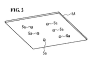
- a projection may be formed on the rigid plate-like member and the load may be applied to the seating sensor 4 in a concentrating manner by means of partially pressing the seating sensor 4 by the projection.
- a plate 5A provided with a plurality of (six in number in FIG. 2) cylindrically shaped projections 5a at a lower face, shown in FIG. 2, may be used instead of the flat shaped plate 5, shown in FIGs. 1a and 1b.
- the projection may be provided not on the plate but on a portion in the supporting member 2, in FIGs. 1a and 1b, where the sensor 4 is overlapped thereon, and further, the projection may be provided at an upper face or a lower face of the sensor 4, in FIGs. 1a and 1b.
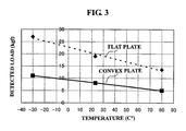
- FIG. 3 is a graph showing a relationship between temperature and a minimum load to be detected by the sensor (detected load), when either one of the plate 5A having a projection at a lower face, or the flat shaped plate 5 without having the projection, is overlapped with an upper face of the sensor, and the pad is disposed thereon and a load is applied thereto from above the pad.
- the projection of the plate 5A having the projection has a cylindrical shape of about 5.0 mm in diameter and about 1.0 mm in height.
- the sensor more sensitively detects the load even when an extremely small load is applied when the plate having the projection is used, across an entire temperature measurement range (from -30 degrees to 80 degrees Celcius).
- sensitivity of the sensor can be improved without using a sensor having high sensitivity, by means of using the plate having the projection.
- the reason why the detected load increases as the temperature gets lower is that the hardening of the pad in such a low temperature makes it harder to fully transmit the load applied on the upper face of the pad up to the lower face of the pad. It is further reasoned that the sensor provided with a plate having the projection offers relatively small variations of the detected load attributable to temperature even when the pad is hardened to some degrees because a projection provided on the plate having the projection achieves a local loading to the sensor.
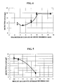
- FIG. 4 is a graph showing a variation of the detected load in a case when the diameter of the projection is varied when a height of the projection is determined to be a constant value of 1.0 mm.
- the detected load is measured by overlapping the face of the plate having the projection, on which the projection is provided, with the upper face of the sensor, and by applying the load from above the pad that is disposed thereupon, in a similar manner as performed in the case in FIG. 3.
- the detected load is caused to be small when the diameter of the projection is brought to be equal to or less than 10 mm, and the sensitivity is thereby improved.
- the diameter of the projection is preferable to be from 3 to 8 mm.
- FIG. 5 is a graph showing a variation of the detected load in a case when the diameter of the projection is set to be a constant value of 5 mm and the height of the projection is varied. In the same manner as that in FIG. 4, the detected load is measured.
- the height of the projection is preferable to be from about 1.0 to about 2.5 mm.
- the pad, the sensor, and the rigid plate-like member are integrally molded by means of the foaming molding process, however, only the pad may be molded first, and the sensor and the rigid plate-like member may be attached thereafter. As another option, either the sensor or the rigid plate-like member, and the pad may be integrally molded first, and the other one of the sensor or the rigid plate-like member may be attached to that thereafter.
- FIG. 6 is a cross-section illustrating the seat with the seating sensor according to the embodiment in which the pad and the seating sensor are separately formed.
- the seat with the seating sensor 10 is provided with a seat cushion 11 and a seat back 12, and the seat cushion 11 is provided with a pad 13 formed of foam such as urethane foam or the like.
- the pad 13 is provided on a seat frame 15 and a sheet-like seating sensor 14 is disposed between the seat frame 15 and the pad.
- a portion in the seat frame 15 where the seating sensor 14 touches may be a seat pan formed of metal or the like, or a spring may be also applicable.
- the seat with the seating sensor 10 is configured such that the pad 13 and the seating sensor 14 are separately formed and therefore manufacturing work is extremely easy and in addition, when a fault or a malfunction occurs with the seating sensor 14, only the seating sensor 14 can be replaced.
- the rigid plate-like member similar to that in the above-described embodiment may be disposed on at least one of the upper side and the lower side of the seating sensor 14.
- the rigid plate-like member is not always necessary to be provided.
- the seating sensor 14 may be attached to the seat frame 15 by means of an adhesive agent. When the seating sensor 14 is thus configured, a positional accuracy of the seating sensor 14 is improved and an assembling work for the seat with the seating sensor 10 is made to be easy.
Landscapes
- Engineering & Computer Science (AREA)
- Mechanical Engineering (AREA)
- Aviation & Aerospace Engineering (AREA)
- Transportation (AREA)
- Seats For Vehicles (AREA)
- Chair Legs, Seat Parts, And Backrests (AREA)
- Mattresses And Other Support Structures For Chairs And Beds (AREA)
Applications Claiming Priority (4)
| Application Number | Priority Date | Filing Date | Title |
|---|---|---|---|
| JP2003158228 | 2003-06-03 | ||
| JP2003326413 | 2003-09-18 | ||
| JP2004036495A JP2005112335A (ja) | 2003-06-03 | 2004-02-13 | 着座センサ付き座席及び座席用パッド |
| PCT/JP2004/007473 WO2004107919A1 (ja) | 2003-06-03 | 2004-05-31 | 着座センサ付き座席及び座席用パッド |
Publications (2)
| Publication Number | Publication Date |
|---|---|
| EP1634516A1 true EP1634516A1 (de) | 2006-03-15 |
| EP1634516A4 EP1634516A4 (de) | 2010-07-07 |
Family
ID=33514555
Family Applications (1)
| Application Number | Title | Priority Date | Filing Date |
|---|---|---|---|
| EP04745438A Withdrawn EP1634516A4 (de) | 2003-06-03 | 2004-05-31 | Sitz mit sitzsensor und sitzkissen |
Country Status (5)
| Country | Link |
|---|---|
| US (1) | US20060091708A1 (de) |
| EP (1) | EP1634516A4 (de) |
| JP (1) | JP2005112335A (de) |
| CA (1) | CA2527887A1 (de) |
| WO (1) | WO2004107919A1 (de) |
Cited By (5)
| Publication number | Priority date | Publication date | Assignee | Title |
|---|---|---|---|---|
| EP1958749A1 (de) * | 2007-02-14 | 2008-08-20 | IEE INTERNATIONAL ELECTRONICS & ENGINEERING S.A. | Verfahren zur Bereitstellung eines Schaumelements mit einem flexiblen Sensor |
| EP2243659A1 (de) * | 2009-04-22 | 2010-10-27 | IEE International Electronics & Engineering S.A. | Verfahren zur Herstellung eines Schaumelements |
| WO2019149602A1 (de) * | 2018-01-30 | 2019-08-08 | Audi Ag | Schaumteil eines kraftfahrzeugsitzes mit sitzbelegungserkennung sowie verfahren zur herstellung eines solchen |
| EP2492137B1 (de) * | 2011-02-24 | 2020-04-22 | I.G. Bauerhin GmbH | Belegungserfassungseinrichtung zum Detektieren des Belegungszustandes eines Kraftfahrzeugsitzes |
| US10933769B2 (en) | 2016-02-22 | 2021-03-02 | Fujikura Ltd. | Load detection sensor unit |
Families Citing this family (13)
| Publication number | Priority date | Publication date | Assignee | Title |
|---|---|---|---|---|
| DE202004019805U1 (de) * | 2004-12-23 | 2005-06-23 | Robert Bosch Gmbh | Sensormatte |
| EP1712403A1 (de) * | 2005-04-12 | 2006-10-18 | IEE INTERNATIONAL ELECTRONICS & ENGINEERING S.A. | Verfahren zum Einbauen eines Sitzsensors im Sitzteil eines Sitzes. |
| JP4711423B2 (ja) * | 2006-04-14 | 2011-06-29 | 本田技研工業株式会社 | 乗車検知装置 |
| JP5047550B2 (ja) * | 2006-07-10 | 2012-10-10 | 日本発條株式会社 | 車両用シート |
| US20080036110A1 (en) * | 2006-08-14 | 2008-02-14 | David Brooker | Foam in place seat cushion using dual fabric trim cover and featureless tool |
| JP5103027B2 (ja) | 2007-01-29 | 2012-12-19 | トヨタ紡織株式会社 | 車両用シート |
| JP5103028B2 (ja) | 2007-01-29 | 2012-12-19 | トヨタ紡織株式会社 | 車両用シート |
| JP5054153B2 (ja) * | 2010-05-31 | 2012-10-24 | パナソニック株式会社 | マッサージ機 |
| JP5669714B2 (ja) * | 2011-11-25 | 2015-02-12 | トヨタ自動車株式会社 | 車両用シート及び車両用シート装置 |
| JP2014172511A (ja) * | 2013-03-08 | 2014-09-22 | Denso Corp | 乗員着座検知用荷重検出装置の取付け構造 |
| JP5979058B2 (ja) | 2013-03-29 | 2016-08-24 | トヨタ紡織株式会社 | 乗物用シート |
| JP6213195B2 (ja) * | 2013-12-03 | 2017-10-18 | アイシン精機株式会社 | 着座検知装置 |
| JP2019182329A (ja) * | 2018-04-16 | 2019-10-24 | テイ・エス テック株式会社 | シートへのセンサーの配置構造及び車両用シート |
Family Cites Families (16)
| Publication number | Priority date | Publication date | Assignee | Title |
|---|---|---|---|---|
| JPS5648212Y2 (de) * | 1979-04-02 | 1981-11-11 | ||
| US4555141A (en) * | 1983-08-05 | 1985-11-26 | Tachikawa Spring Co. Ltd. | Vehicle seat |
| US5232243A (en) * | 1991-04-09 | 1993-08-03 | Trw Vehicle Safety Systems Inc. | Occupant sensing apparatus |
| US6012007A (en) * | 1995-12-01 | 2000-01-04 | Delphi Technologies, Inc. | Occupant detection method and apparatus for air bag system |
| JPH09182647A (ja) * | 1995-12-28 | 1997-07-15 | Nhk Spring Co Ltd | シート装置 |
| DE19601969A1 (de) * | 1996-01-20 | 1997-07-24 | Daimler Benz Ag | Elektrisch kontaktierbare Funktionsmatte, insbesondere Sensormatte oder Heizmatte |
| US5986221A (en) * | 1996-12-19 | 1999-11-16 | Automotive Systems Laboratory, Inc. | Membrane seat weight sensor |
| US6109117A (en) * | 1996-12-19 | 2000-08-29 | Automotive Systems Laboratory, Inc. | Seat weight sensor |
| JPH1134710A (ja) * | 1997-07-24 | 1999-02-09 | Bridgestone Corp | 着座センサ付き座席 |
| US6129168A (en) * | 1997-11-19 | 2000-10-10 | Breed Automotive Technology, Inc. | Weight sensor for vehicular safety restraint systems |
| US6259167B1 (en) * | 1998-07-09 | 2001-07-10 | Peter Norton | Seat occupant weight sensing system |
| US6476514B1 (en) * | 2000-03-29 | 2002-11-05 | Ford Global Technologies, Inc. | Occupant detection sensor assembly for seats |
| JP3707363B2 (ja) * | 2000-06-28 | 2005-10-19 | 株式会社デンソー | 車両用シートセンサ |
| JP2002067765A (ja) * | 2000-08-25 | 2002-03-08 | Denso Corp | 乗員判別システム |
| JPWO2002041736A1 (ja) * | 2000-11-21 | 2004-03-25 | 株式会社ブリヂストン | 車両用シートパッド |
| JP4482785B2 (ja) * | 2001-09-13 | 2010-06-16 | 株式会社デンソー | 車両用着座者判定装置 |
-
2004
- 2004-02-13 JP JP2004036495A patent/JP2005112335A/ja active Pending
- 2004-05-31 EP EP04745438A patent/EP1634516A4/de not_active Withdrawn
- 2004-05-31 CA CA 2527887 patent/CA2527887A1/en not_active Abandoned
- 2004-05-31 WO PCT/JP2004/007473 patent/WO2004107919A1/ja not_active Ceased
-
2005
- 2005-12-02 US US11/291,978 patent/US20060091708A1/en not_active Abandoned
Cited By (11)
| Publication number | Priority date | Publication date | Assignee | Title |
|---|---|---|---|---|
| EP1958749A1 (de) * | 2007-02-14 | 2008-08-20 | IEE INTERNATIONAL ELECTRONICS & ENGINEERING S.A. | Verfahren zur Bereitstellung eines Schaumelements mit einem flexiblen Sensor |
| WO2008098966A1 (en) * | 2007-02-14 | 2008-08-21 | Iee International Electronics & Engineering S.A. | Method for providing a foam element with a flexible sensor |
| EP2243659A1 (de) * | 2009-04-22 | 2010-10-27 | IEE International Electronics & Engineering S.A. | Verfahren zur Herstellung eines Schaumelements |
| WO2010121996A1 (en) * | 2009-04-22 | 2010-10-28 | Iee International Electronics & Engineering S.A. | Foam element production method |
| CN102421636A (zh) * | 2009-04-22 | 2012-04-18 | Iee国际电子工程股份公司 | 泡沫元件的制造方法 |
| EP2492137B1 (de) * | 2011-02-24 | 2020-04-22 | I.G. Bauerhin GmbH | Belegungserfassungseinrichtung zum Detektieren des Belegungszustandes eines Kraftfahrzeugsitzes |
| US10933769B2 (en) | 2016-02-22 | 2021-03-02 | Fujikura Ltd. | Load detection sensor unit |
| WO2019149602A1 (de) * | 2018-01-30 | 2019-08-08 | Audi Ag | Schaumteil eines kraftfahrzeugsitzes mit sitzbelegungserkennung sowie verfahren zur herstellung eines solchen |
| KR20200105927A (ko) * | 2018-01-30 | 2020-09-09 | 아우디 아게 | 시트 점유 감지 기능을 갖는 자동차 시트의 발포체 부품 및 그 제조 방법 |
| US11117492B2 (en) | 2018-01-30 | 2021-09-14 | Audi Ag | Foam part of a motor vehicle seat having seat occupancy detection, and method for the production thereof |
| KR102366542B1 (ko) | 2018-01-30 | 2022-02-23 | 아우디 아게 | 시트 점유 감지 기능을 갖는 자동차 시트의 발포체 부품 및 그 제조 방법 |
Also Published As
| Publication number | Publication date |
|---|---|
| US20060091708A1 (en) | 2006-05-04 |
| WO2004107919A1 (ja) | 2004-12-16 |
| EP1634516A4 (de) | 2010-07-07 |
| JP2005112335A (ja) | 2005-04-28 |
| CA2527887A1 (en) | 2004-12-16 |
Similar Documents
| Publication | Publication Date | Title |
|---|---|---|
| EP1634516A1 (de) | Sitz mit sitzsensor und sitzkissen | |
| US20090261639A1 (en) | Seat with seat sensor | |
| JP3707363B2 (ja) | 車両用シートセンサ | |
| US20100109390A1 (en) | Vehicle seat | |
| CN104379398A (zh) | 车座悬置垫 | |
| US9428080B2 (en) | Seat occupancy sensor unit for seat with spring suspension or seat pan | |
| US7942477B1 (en) | Seat provided with electric or electronic equipment | |
| US20140375105A1 (en) | Vehicle seat and method of manufacturing the same | |
| US6546822B1 (en) | Seat occupant sensor device | |
| JP2009507698A (ja) | センサマットを備えるシートフォーム | |
| US11958415B2 (en) | Pad with speaker retention bracket | |
| JP2017001455A (ja) | 乗物用シートのクッション部材 | |
| US9283867B2 (en) | Conveyance seat | |
| JP2008535704A (ja) | シートクッション中へのシートセンサの取り付け方法 | |
| CN100496337C (zh) | 带就座传感器的座席及座席用衬垫 | |
| JP2013112315A (ja) | 座席装置 | |
| US11007901B2 (en) | Seat | |
| JP7097461B6 (ja) | シート使用の検出機能を備えた自動車シートの発泡部品およびその製造方法 | |
| JP2000139617A (ja) | 面状部品装備シート | |
| US20080315639A1 (en) | Foam Seat with Sensor | |
| JP2016120798A (ja) | 着座検知装置 | |
| JP2001160332A (ja) | 着座検知装置 | |
| JP5223588B2 (ja) | 内装材の移動規制部材及び移動規制構造 | |
| JPWO2019239911A1 (ja) | シートパッド | |
| JP2004239691A (ja) | 感圧センサ及び該感圧センサの座席シートへの取付方法 |
Legal Events
| Date | Code | Title | Description |
|---|---|---|---|
| PUAI | Public reference made under article 153(3) epc to a published international application that has entered the european phase |
Free format text: ORIGINAL CODE: 0009012 |
|
| 17P | Request for examination filed |
Effective date: 20051214 |
|
| AK | Designated contracting states |
Kind code of ref document: A1 Designated state(s): AT BE BG CH CY CZ DE DK EE ES FI FR GB GR HU IE IT LI LU MC NL PL PT RO SE SI SK TR |
|
| DAX | Request for extension of the european patent (deleted) | ||
| A4 | Supplementary search report drawn up and despatched |
Effective date: 20100607 |
|
| STAA | Information on the status of an ep patent application or granted ep patent |
Free format text: STATUS: THE APPLICATION IS DEEMED TO BE WITHDRAWN |
|
| 18D | Application deemed to be withdrawn |
Effective date: 20100904 |