EP1632818A2 - Unité de protection du photoconducteur et appareil de formation d'images - Google Patents
Unité de protection du photoconducteur et appareil de formation d'images Download PDFInfo
- Publication number
- EP1632818A2 EP1632818A2 EP05255008A EP05255008A EP1632818A2 EP 1632818 A2 EP1632818 A2 EP 1632818A2 EP 05255008 A EP05255008 A EP 05255008A EP 05255008 A EP05255008 A EP 05255008A EP 1632818 A2 EP1632818 A2 EP 1632818A2
- Authority
- EP
- European Patent Office
- Prior art keywords
- link
- door
- photosensitive medium
- unit
- photosensitive
- Prior art date
- Legal status (The legal status is an assumption and is not a legal conclusion. Google has not performed a legal analysis and makes no representation as to the accuracy of the status listed.)
- Withdrawn
Links
Images


Classifications
-
- G—PHYSICS
- G03—PHOTOGRAPHY; CINEMATOGRAPHY; ANALOGOUS TECHNIQUES USING WAVES OTHER THAN OPTICAL WAVES; ELECTROGRAPHY; HOLOGRAPHY
- G03G—ELECTROGRAPHY; ELECTROPHOTOGRAPHY; MAGNETOGRAPHY
- G03G15/00—Apparatus for electrographic processes using a charge pattern
- G03G15/04—Apparatus for electrographic processes using a charge pattern for exposing, i.e. imagewise exposure by optically projecting the original image on a photoconductive recording material
- G03G15/043—Apparatus for electrographic processes using a charge pattern for exposing, i.e. imagewise exposure by optically projecting the original image on a photoconductive recording material with means for controlling illumination or exposure
-
- G—PHYSICS
- G03—PHOTOGRAPHY; CINEMATOGRAPHY; ANALOGOUS TECHNIQUES USING WAVES OTHER THAN OPTICAL WAVES; ELECTROGRAPHY; HOLOGRAPHY
- G03G—ELECTROGRAPHY; ELECTROPHOTOGRAPHY; MAGNETOGRAPHY
- G03G21/00—Arrangements not provided for by groups G03G13/00 - G03G19/00, e.g. cleaning, elimination of residual charge
- G03G21/16—Mechanical means for facilitating the maintenance of the apparatus, e.g. modular arrangements
- G03G21/1604—Arrangement or disposition of the entire apparatus
- G03G21/1623—Means to access the interior of the apparatus
- G03G21/1633—Means to access the interior of the apparatus using doors or covers
-
- G—PHYSICS
- G03—PHOTOGRAPHY; CINEMATOGRAPHY; ANALOGOUS TECHNIQUES USING WAVES OTHER THAN OPTICAL WAVES; ELECTROGRAPHY; HOLOGRAPHY
- G03G—ELECTROGRAPHY; ELECTROPHOTOGRAPHY; MAGNETOGRAPHY
- G03G2215/00—Apparatus for electrophotographic processes
- G03G2215/01—Apparatus for electrophotographic processes for producing multicoloured copies
- G03G2215/0103—Plural electrographic recording members
- G03G2215/0119—Linear arrangement adjacent plural transfer points
-
- G—PHYSICS
- G03—PHOTOGRAPHY; CINEMATOGRAPHY; ANALOGOUS TECHNIQUES USING WAVES OTHER THAN OPTICAL WAVES; ELECTROGRAPHY; HOLOGRAPHY
- G03G—ELECTROGRAPHY; ELECTROPHOTOGRAPHY; MAGNETOGRAPHY
- G03G2221/00—Processes not provided for by group G03G2215/00, e.g. cleaning or residual charge elimination
- G03G2221/16—Mechanical means for facilitating the maintenance of the apparatus, e.g. modular arrangements and complete machine concepts
- G03G2221/1606—Mechanical means for facilitating the maintenance of the apparatus, e.g. modular arrangements and complete machine concepts for the photosensitive element
- G03G2221/1609—Mechanical means for facilitating the maintenance of the apparatus, e.g. modular arrangements and complete machine concepts for the photosensitive element protective arrangements for preventing damage
-
- G—PHYSICS
- G03—PHOTOGRAPHY; CINEMATOGRAPHY; ANALOGOUS TECHNIQUES USING WAVES OTHER THAN OPTICAL WAVES; ELECTROGRAPHY; HOLOGRAPHY
- G03G—ELECTROGRAPHY; ELECTROPHOTOGRAPHY; MAGNETOGRAPHY
- G03G2221/00—Processes not provided for by group G03G2215/00, e.g. cleaning or residual charge elimination
- G03G2221/16—Mechanical means for facilitating the maintenance of the apparatus, e.g. modular arrangements and complete machine concepts
- G03G2221/1678—Frame structures
- G03G2221/169—Structural door designs
Definitions
- the present invention relates to electrophotographic image forming apparatus. More particularly, the present invention relates to units for screening a photosensitive medium and electrophotographic image forming apparatus having the same.
- an electrophotographic image forming apparatus such as a laser printer or a digital copying machine, is a device in which an electrostatic latent image is formed on an outer circumference of a photosensitive medium charged to a predetermined electric potential by scanning light onto the photosensitive medium.
- Toner which is a developing agent, is injected into the electrostatic latent image and is developed as a visible image. The image is then transferred onto paper and fused on the paper so that an image is printed.
- Light fatigue of the photosensitive medium wherein sensitivity with respect to light is reduced, occurs when the photosensitive medium is used for a long time. When a clear image cannot be printed any more, the photosensitive medium is replaced with a new one.
- the electrophotographic image forming apparatus generally includes a unit for screening the photosensitive medium to maximize the life of the photosensitive medium.
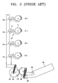
- FIGS. 1 and 2 respectively illustrate an example of a conventional unit for screening a photosensitive medium. That is, FIG. 1 illustrates opened shutters for the photosensitive medium. FIG. 2 illustrates closed shutters for the photosensitive medium.
- the conventional unit for screening a photosensitive medium includes four shutters 10 that are elastically biased in a direction in which each photosensitive medium 1 is screened.
- a link 15 has four pushers 16 that push each of the shutters 10 to expose each photosensitive medium 1.
- First and second gears 20 and 26 connect a door 30 of an image forming apparatus to the link 15, a cam 22, and a pair of springs 24 and 28.
- the image forming apparatus is a device that prints a color image and includes four photosensitive media on which an image having a single color such as cyan (C), magenta (M), yellow (Y), or black (K) is formed.
- each of the four photosensitive media 1 is mounted in one of the developing units that respectively stores a toner having a color, such as cyan (C), magenta (M), yellow (Y), and black (K).
- a toner having a color such as cyan (C), magenta (M), yellow (Y), and black (K).
- Each of the four shutters 10 screens one photosensitive medium 1 and is disposed in one of the developing units. Additionally, the four pushers 16 that push the four shutters 10 are placed in a lengthwise direction of the link 15.
- each pusher 16 does not press each lever 11 of each shutter 10 any more and each shutter 10 moves by an elastic restoration force to screen each photosensitive medium 1 from external light in a direction indicated by the arrow, as shown in FIG. 2.
- Preferred embodiments of the present invention aim to provide a unit for screening a photosensitive medium having a reduced number of parts, and an electrophotographic image forming apparatus having the unit.
- Preferred embodiments of the present invention also aim to provide a unit for screening a photosensitive medium having a simple structure and an improved operational reliability, and an electrophotographic image forming apparatus having the same.
- a unit for screening a photosensitive medium in an electrophotographic image forming apparatus includes a shutter elastically biased in a direction in which the photosensitive medium is screened.
- a first link which is capable of making a straight reciprocating motion in a first direction, has a pusher pressing and pushing the shutter to expose the photosensitive medium.
- a second link which is connected to the first link, makes a straight reciprocating motion in a second direction not parallel to the first direction. When a door of the electrophotographic image forming apparatus is closed, the second link moves so that the first link moves in a direction in which the photosensitive medium is exposed.
- the second link may include a guide groove extending in the direction not parallel to the first direction.
- the first link may include a guide protrusion placed in the guide groove. When the second link moves in the second direction, the guide protrusion may slide in the guide groove and moves the first link in the first direction.
- the first direction may be a vertical line
- the second direction may be a horizontal line
- the guide groove may extend in a third direction along an oblique line.
- a plurality of photosensitive media and a plurality of shutters screening the plurality of photosensitive media may be placed along a direction in which the first link extends.
- the first link may include a plurality of pushers pressing and pushing the plurality of shutters.
- the second link may be elastically supported by a spring so that the second link returns to its original position when the door is closed and opened again.
- an electrophotographic image forming apparatus includes a case having a door, and a photosensitive medium that is inserted and mounted inside the case by opening the door.
- a unit screens the photosensitive medium when the door is opened.
- the unit for screening a photosensitive medium includes a shutter elastically biased in a direction in which the photosensitive medium is screened.
- a first link which is capable of making a straight reciprocating motion in a first direction, has a pusher pressing and pushing the shutter to expose the photosensitive medium.
- a second link which is connected to the first link, makes a straight reciprocating motion in a second direction not parallel to the first direction. When the door is closed, the second link moves so that the first link moves in a direction in which the photosensitive medium is exposed.
- the second link may include a guide groove extending in the direction not parallel to the first direction.
- the first link may include a guide protrusion placed in the guide groove. When the second link moves in the second direction, the guide protrusion may slide in the guide groove and moves the first link in the first direction.
- the first direction may be a vertical line
- the second direction may be a horizontal line
- the guide groove may extend in a third direction along an oblique line.
- a plurality of photosensitive media and a plurality of shutters screening the plurality of photosensitive media may be placed along a direction in which the first link extends.
- the first link may include a plurality of pushers pressing and pushing the plurality of shutters.
- the second link may be elastically supported by a spring so that the second link returns to its original position after the door is opened again.
- FIGS. 1 and 2 illustrate an example of a conventional unit for screening a photosensitive medium
- FIG. 3 is an elevational view in partial cross section of an electrophotographic image forming apparatus according to an exemplary embodiment of the present invention
- FIG. 4 is an elevational view of a developing unit of FIG. 3;
- FIGS. 5 and 6 are elevational views of a unit for screening a photosensitive medium according to exemplary embodiments of the present invention.
- FIG. 7 is an elevational view in cross section taken along line VII-VII of FIG. 6 of a guide protrusion of a first link received by a guide groove.
- FIG. 3 is an elevational view in partial cross section of an electrophotographic image forming apparatus according to an exemplary embodiment of the present invention.
- FIG. 4 is an elevational view of a developing unit shown of FIG. 3.
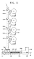
- FIGS. 5 and 6 are elevational views of a unit for screening a photosensitive medium according to exemplary embodiments of the present invention.
- FIG. 5 is an elevational view of a photosensitive medium in which the shutters are opened.
- FIG. 6 is an elevational view of a photosensitive medium in which the shutters are closed.
- FIG. 7 is an elevational view in cross section taken along line VII-VII of FIG. 6 of a guide protrusion of a first link received by a guide groove.
- an electrophotographic image forming apparatus 100 includes four developing units 110 placed inside a case 101, four light scanning units (LSUs) 165, a carrier belt 150, four transfer rollers 155, and a fusing unit 160.
- the electrophotographic image forming apparatus 100 further includes a cassette 157 on which paper is stacked, a pickup roller 158 that picks up a sheet of paper from the cassette 157, a feed roller 159 which feeds the picked-up paper, and a paper exiting roller 162 which discharges the paper on which an image is printed outside the case 101.
- the four developing units 110 are replaced with new ones when toner, which is used as a developing agent, is exhausted.
- the four developing units 110 include four developing units 110C, 110M, 110Y, and 110K, each of which respectively store a toner having a color such as cyan (C), magenta (M), yellow (Y), and black (K).
- C cyan
- M magenta
- Y yellow
- K black
- the carrier belt 150 and rollers 151 to 155 supporting the carrier belt 150 are arranged in a widthwise direction so that the developing units 110C, 110M, 110Y, and 110K in which a toner is exhausted may be replaced with new ones.
- the carrier belt 150 is supported by a plurality of support rollers 151 to 154 and circulates in a vertical direction.
- four LSUs 165C, 165M, 165Y, and 165K are installed to correspond to the four developing units 110C, 110M, 110Y, and 110K.
- Each of the LSUs 165C, 165M, 165Y, and 165K scans a beam corresponding to image information about cyan (C), magenta (M), yellow (Y), and black (K) colors onto each photosensitive drum 114 that is a photosensitive medium mounted in each housing 111 of each of the developing units 110C, 110M, 110Y, and 110K.
- the LSUs 165C, 165M, 165Y, and 165K may be laser scanning units that use a laser diode as a light source.
- Each of the developing units 110C, 110M, 110Y, and 110K has a photosensitive drum 114 disposed inside each housing 111 and a developing roller 115. To transfer an image onto a piece of paper, a portion of an outer circumference of each photosensitive drum 114 that faces the carrier belt 150 is exposed to an outside of each housing 111 when the image is printed. Additionally, each of the developing units 110C, 110M, 110Y, and 110K has a charging roller 119. A charging bias voltage is applied to each charging roller 119 so that an outer circumference of the photosensitive drum 114 is charged to a uniform electric potential. A corona discharger (not shown) instead of the charging roller 119 may be used.
- Each developing roller 115 supplies toner to the photosensitive drum 114 by adhering the toner to the outer circumference of the photosensitive drum 114.
- a development bias voltage is applied to each developing roller 115 to supply toner to the photosensitive drum 114.
- a supplying roller that supplies toner to each developing roller 115, a doctor blade that regulates the amount of toner adhered to each developing roller 115, and a conveyor-shaped agitator that transfers toner held in each housing 111 to the supplying roller are further provided inside the housing 111 of each of the developing units 110C, 110M, 110Y, and 110K.
- Each of the developing units 110C, 110M, 110Y, and 110K in an exemplary embodiment includes an opening 112 that forms a path so that the beam scanned by the LSUs 165C, 165M, 165Y, and 165K is irradiated onto the photosensitive drum 114.
- Each of the four transfer rollers 155 is disposed to face each photosensitive drum 114 of each of the developing units 110C, 110M, 110Y, and 110K when the carrier belt 150 is placed between each transfer roller 155 and each photosensitive drum 114.
- a transfer bias voltage is applied to the transfer roller 155.
- Each photosensitive drum 114 of each of the developing units 110C, 110M, 110Y, and 110K is charged to a uniform electric potential by the charging bias voltage applied to the charging roller 120.
- Each of the LSUs 165C, 165M, 165Y, and 165K scans a beam corresponding to image information about cyan (C), magenta (M), yellow (Y), and black (K) colors onto each photosensitive drum 114 of each of the developing units 110C, 110M, 110Y, and 110K through the opening 112 so that an electrostatic latent image is formed on the outer circumference of the photosensitive drum 114.
- a development bias voltage is applied to the developing roller 115.
- the toner moves from the developing roller 115 onto the outer circumference of the photosensitive drum 114 so that visible images having colors, such as cyan (C), magenta (M), yellow (Y), and black (K), are formed on the outer circumference of the photosensitive drum 114 of each of the developing units 110C, 110M, 110Y, and 110K.
- colors such as cyan (C), magenta (M), yellow (Y), and black (K)
- the paper is picked up by the pickup roller 158 from the cassette 157 and inserted into the carrier belt 150 by the feed roller 159.
- the paper is attached to the surface of the carrier belt 150 by an electrostatic force and fed at the same velocity as a traveling linear velocity of the carrier belt 150.
- the paper As the paper is transferred continuously, visible images of colors such as magenta (M), yellow (Y), and black (K) formed on the outer circumference of each photosensitive drum 114 of the other developing units 110M, 110Y, and 110K overlap with one another sequentially and are transferred onto the paper so that visible color images are formed on the paper.
- the fusing unit 160 fuses the visible color images on the paper by applying heat and pressure to the visible color images.
- the paper on which the visible color images are fused is discharged outside the case 101 by the paper exiting roller 162.
- the electrophotographic image forming apparatus 100 further includes a unit for screening a photosensitive medium to substantially prevent the photosensitive medium 114 from being exposed to external light when the door 102 is opened.
- the unit for screening the photosensitive medium includes a shutter 120 and first and second links 130 and 140 that make a reciprocating motion in a direction in which the first and second links 130 and 140 cross with each other.
- the shutter 120 is rotatably mounted in the housing 111 of the developing unit 110 and has a screen 127 for screening the photosensitive drum 114.
- the screen 127 is hingedly coupled with each end of a first arm 122 mounted on a side of the housing 111 to be rotated around a first hinge shaft 123.
- Each end of a second arm 124 is rotatably mounted to a second hinge shaft 125.
- the first and second hinge shafts 123 and 125 do not coincide with a rotational center 114a of the photosensitive drum 114.
- the rotational radius of the first arm 122 is preferably larger than that of the second arm 124.
- the screen 127 may be close to the photosensitive drum 114 along an outer circumference contour line of the photosensitive drum 114 when the screen 127 screens the photosensitive drum 114, as indicated by a double-dashed line, and light may be effectively prevented from being streamed on the photosensitive drum. Additionally, damage, such as scratching the photosensitive drum 114 caused by the screen 127, is substantially prevented even when the screen 127 descends so that the photosensitive drum 114 is exposed.
- a torsion spring is disposed in the vicinity of the first hinge shaft 123 to elastically bias the first arm 122 to rotate counterclockwise, that is, in a direction in which the screen 127 screens the photosensitive drum 114.
- a lever 129 is disposed in the vicinity of the first hinge shaft 123. The lever 129 extends in a direction substantially opposite to the first arm 122 from the first hinge shaft 123. Thus, if the lever 129 is pressed and pulled in an upward direction, the first arm 122 and the screen 127 coupled with the first arm 122 descend and the photosensitive drum 114 is exposed.
- the housing 111 of the developing unit 110 and the second arm 124 of the shutter 120 are not shown in FIGS. 5 and 6.
- the first link 130 is a bar-shaped member that extends in a first direction i, a substantially vertical line, and is mounted inside a case (see 101 of FIG. 3) to make a substantially straight reciprocating motion.
- Four pushers 131 which push each lever 129 of the shutters 120 arranged in a vertical direction together with the photosensitive drum 114, are arranged in the first link 130 in a line.
- Each of the four pushers 131 protrudes from a side of the first link 130 in a substantially horizontal direction and is disposed under each of the levers 129.
- a guide protrusion 134 is placed in a bottom end of the first link 130.
- a second link 140 is a bar-shaped member that extends in a second direction ii, a substantially horizontal line, and is mounted inside the case (see 101 of FIG. 3) to make a straight reciprocating motion.
- a guide groove 145 extends in a third direction iii, an oblique line, is disposed in one end of the second link 140.
- a guide protrusion 134 of the first link 130 is held in the guide groove 145.
- a straight reciprocating motion in the second direction ii of the second link 140 is changed into a straight reciprocating motion in the first direction i of the first link 130.
- a spring 142 is inserted in the second link 140.
- One end of the spring 142 is engaged with an engagement protrusion 143 fixedly connected to the second link 140, and the other end of the spring 142 is engaged with an engagement protrusion 105 fixedly connected to an inside of the case 101.
- the spring 142 is preferably a tension spring. In FIG. 6, the spring 142 is shown in a neutral state. In FIG. 5, the spring 142 is in an extended state.
- the second link 140 When the door 102 is closed, as shown in FIG. 5, the second link 140 is pushed by the protrusion 102a of the door 102 and the guide protrusion 134 is pushed on a slanted surface of the guide groove 145 and ascends. As such, the pusher 131 of the first link 130 ascends and pushes the lever 129. The screen 127 descends, and the photosensitive drum 114 is exposed. The image forming apparatus is now in a state where a printing operation may be performed.
- the second link 140 moves to the right by a restoration force generated by the tension spring 142, as shown in FIG. 6, and the guide protrusion 134 is pushed on a slanted surface of the guide groove 145 and descends again.
- the pusher 131 of the first link 130 descends again, the screen 127 ascends, and the photosensitive drum 114 is prevented from being exposed.
- the unit for screening the photosensitive medium has a reduced number of parts and a simple structure, and an operational reliability thereof is improved. Additionally, the size of the unit for screening the photosensitive medium is reduced.
Landscapes
- Physics & Mathematics (AREA)
- General Physics & Mathematics (AREA)
- Electrophotography Configuration And Component (AREA)
Applications Claiming Priority (1)
| Application Number | Priority Date | Filing Date | Title |
|---|---|---|---|
| KR1020040070794A KR100611990B1 (ko) | 2004-09-06 | 2004-09-06 | 감광매체 스크린 장치 및 이를 구비한 전자사진방식화상형성장치 |
Publications (2)
| Publication Number | Publication Date |
|---|---|
| EP1632818A2 true EP1632818A2 (fr) | 2006-03-08 |
| EP1632818A3 EP1632818A3 (fr) | 2006-09-20 |
Family
ID=36166360
Family Applications (1)
| Application Number | Title | Priority Date | Filing Date |
|---|---|---|---|
| EP05255008A Withdrawn EP1632818A3 (fr) | 2004-09-06 | 2005-08-12 | Unité de protection du photoconducteur et appareil de formation d'images |
Country Status (4)
| Country | Link |
|---|---|
| US (1) | US20060051127A1 (fr) |
| EP (1) | EP1632818A3 (fr) |
| KR (1) | KR100611990B1 (fr) |
| CN (1) | CN1746786A (fr) |
Cited By (1)
| Publication number | Priority date | Publication date | Assignee | Title |
|---|---|---|---|---|
| EP2743780A3 (fr) * | 2012-12-12 | 2017-12-13 | S-Printing Solution Co., Ltd. | Dispositif d'élimination de bourrage papier, appareil de formation d'image comprenant celui-ci et procédé d'élimination de bourrage papier |
Families Citing this family (5)
| Publication number | Priority date | Publication date | Assignee | Title |
|---|---|---|---|---|
| JP4586851B2 (ja) * | 2007-12-27 | 2010-11-24 | ブラザー工業株式会社 | 画像形成装置 |
| JP2010122465A (ja) * | 2008-11-19 | 2010-06-03 | Canon Inc | 画像形成装置 |
| JP6708443B2 (ja) * | 2016-03-01 | 2020-06-10 | キヤノン株式会社 | ロック機構及び画像形成装置 |
| JP2019090861A (ja) * | 2017-11-10 | 2019-06-13 | 富士ゼロックス株式会社 | リンク機構および画像形成装置 |
| JP2020160316A (ja) * | 2019-03-27 | 2020-10-01 | 日本電産コパル株式会社 | カメラモジュール遮蔽装置、電子機器 |
Family Cites Families (3)
| Publication number | Priority date | Publication date | Assignee | Title |
|---|---|---|---|---|
| JP4458642B2 (ja) * | 1999-08-31 | 2010-04-28 | キヤノン株式会社 | 画像形成装置 |
| KR100395522B1 (ko) * | 2000-08-25 | 2003-08-25 | 삼성전자주식회사 | 레이저 프린터 |
| JP3634807B2 (ja) * | 2002-02-20 | 2005-03-30 | キヤノン株式会社 | プロセスカートリッジおよび画像形成装置 |
-
2004
- 2004-09-06 KR KR1020040070794A patent/KR100611990B1/ko not_active Expired - Fee Related
-
2005
- 2005-06-03 US US11/143,627 patent/US20060051127A1/en not_active Abandoned
- 2005-08-12 EP EP05255008A patent/EP1632818A3/fr not_active Withdrawn
- 2005-08-15 CN CNA200510091952XA patent/CN1746786A/zh active Pending
Cited By (1)
| Publication number | Priority date | Publication date | Assignee | Title |
|---|---|---|---|---|
| EP2743780A3 (fr) * | 2012-12-12 | 2017-12-13 | S-Printing Solution Co., Ltd. | Dispositif d'élimination de bourrage papier, appareil de formation d'image comprenant celui-ci et procédé d'élimination de bourrage papier |
Also Published As
| Publication number | Publication date |
|---|---|
| CN1746786A (zh) | 2006-03-15 |
| US20060051127A1 (en) | 2006-03-09 |
| KR100611990B1 (ko) | 2006-08-11 |
| EP1632818A3 (fr) | 2006-09-20 |
| KR20060022034A (ko) | 2006-03-09 |
Similar Documents
| Publication | Publication Date | Title |
|---|---|---|
| JP3970274B2 (ja) | プロセスカートリッジ及び電子写真画像形成装置 | |
| KR100910692B1 (ko) | 전자사진 컬러 화상 형성 장치, 프로세스 카트리지 및 전자사진 화상 형성 장치용 이동 부재 | |
| JP5100468B2 (ja) | 画像形成装置 | |
| US5440373A (en) | Color image forming apparatus | |
| JP5910937B2 (ja) | 原稿搬送装置、画像読取装置及び画像形成装置 | |
| US8204422B2 (en) | Image forming apparatus and process cartridge having a charging unit | |
| US9182719B2 (en) | Moving device assembly and image forming apparatus including the moving device assembly | |
| JP4667106B2 (ja) | 画像形成装置 | |
| JP5721349B2 (ja) | 電子写真画像形成装置 | |
| EP1632818A2 (fr) | Unité de protection du photoconducteur et appareil de formation d'images | |
| JP4161246B2 (ja) | 画像形成装置 | |
| JP4621063B2 (ja) | 画像形成装置 | |
| US7286787B2 (en) | Shutter for a developing unit of an electrophotographic image forming apparatus | |
| US7555240B2 (en) | Cover members for an image forming apparatus | |
| JP2004066611A (ja) | 像担持体カートリッジ及びそれを用いた画像形成装置 | |
| JPH04296885A (ja) | 画像形成装置 | |
| JPH11295998A (ja) | 画像形成装置 | |
| JP3837003B2 (ja) | 画像形成装置 | |
| JP7229462B2 (ja) | クリーニング装置、及び、画像形成装置 | |
| JPH03111861A (ja) | カラー画像形成装置 | |
| JP2002214850A (ja) | 画像形成装置及び該画像形成装置を備えた画像形成システム | |
| JP2020134560A (ja) | 画像形成装置、及び、プロセスカートリッジ | |
| JP2006301173A (ja) | 現像装置、及び、プロセスカートリッジ | |
| JP2006251685A (ja) | カラー画像形成装置 | |
| JPH02284173A (ja) | 画像形成装置 |
Legal Events
| Date | Code | Title | Description |
|---|---|---|---|
| PUAI | Public reference made under article 153(3) epc to a published international application that has entered the european phase |
Free format text: ORIGINAL CODE: 0009012 |
|
| 17P | Request for examination filed |
Effective date: 20050812 |
|
| AK | Designated contracting states |
Kind code of ref document: A2 Designated state(s): AT BE BG CH CY CZ DE DK EE ES FI FR GB GR HU IE IS IT LI LT LU LV MC NL PL PT RO SE SI SK TR |
|
| AX | Request for extension of the european patent |
Extension state: AL BA HR MK YU |
|
| PUAL | Search report despatched |
Free format text: ORIGINAL CODE: 0009013 |
|
| AK | Designated contracting states |
Kind code of ref document: A3 Designated state(s): AT BE BG CH CY CZ DE DK EE ES FI FR GB GR HU IE IS IT LI LT LU LV MC NL PL PT RO SE SI SK TR |
|
| AX | Request for extension of the european patent |
Extension state: AL BA HR MK YU |
|
| RIC1 | Information provided on ipc code assigned before grant |
Ipc: G03G 21/16 20060101ALI20060817BHEP Ipc: G03G 15/00 20060101AFI20051213BHEP |
|
| 17Q | First examination report despatched |
Effective date: 20061215 |
|
| AKX | Designation fees paid |
Designated state(s): DE FR GB NL |
|
| 17Q | First examination report despatched |
Effective date: 20061215 |
|
| STAA | Information on the status of an ep patent application or granted ep patent |
Free format text: STATUS: THE APPLICATION IS DEEMED TO BE WITHDRAWN |
|
| 18D | Application deemed to be withdrawn |
Effective date: 20080711 |