EP1632681A2 - Verbundbauteil - Google Patents
Verbundbauteil Download PDFInfo
- Publication number
- EP1632681A2 EP1632681A2 EP05017682A EP05017682A EP1632681A2 EP 1632681 A2 EP1632681 A2 EP 1632681A2 EP 05017682 A EP05017682 A EP 05017682A EP 05017682 A EP05017682 A EP 05017682A EP 1632681 A2 EP1632681 A2 EP 1632681A2
- Authority
- EP
- European Patent Office
- Prior art keywords
- connecting element
- composite component
- component according
- elements
- polycarbonate
- Prior art date
- Legal status (The legal status is an assumption and is not a legal conclusion. Google has not performed a legal analysis and makes no representation as to the accuracy of the status listed.)
- Withdrawn
Links
Images
Classifications
-
- B—PERFORMING OPERATIONS; TRANSPORTING
- B62—LAND VEHICLES FOR TRAVELLING OTHERWISE THAN ON RAILS
- B62D—MOTOR VEHICLES; TRAILERS
- B62D25/00—Superstructure or monocoque structure sub-units; Parts or details thereof not otherwise provided for
- B62D25/06—Fixed roofs
-
- B—PERFORMING OPERATIONS; TRANSPORTING
- B62—LAND VEHICLES FOR TRAVELLING OTHERWISE THAN ON RAILS
- B62D—MOTOR VEHICLES; TRAILERS
- B62D29/00—Superstructures, understructures, or sub-units thereof, characterised by the material thereof
- B62D29/04—Superstructures, understructures, or sub-units thereof, characterised by the material thereof predominantly of synthetic material
- B62D29/048—Connections therefor, e.g. joints
-
- F—MECHANICAL ENGINEERING; LIGHTING; HEATING; WEAPONS; BLASTING
- F16—ENGINEERING ELEMENTS AND UNITS; GENERAL MEASURES FOR PRODUCING AND MAINTAINING EFFECTIVE FUNCTIONING OF MACHINES OR INSTALLATIONS; THERMAL INSULATION IN GENERAL
- F16B—DEVICES FOR FASTENING OR SECURING CONSTRUCTIONAL ELEMENTS OR MACHINE PARTS TOGETHER, e.g. NAILS, BOLTS, CIRCLIPS, CLAMPS, CLIPS OR WEDGES; JOINTS OR JOINTING
- F16B2200/00—Constructional details of connections not covered for in other groups of this subclass
- F16B2200/97—Constructional details of connections not covered for in other groups of this subclass having differing thermal expansion coefficients
-
- Y—GENERAL TAGGING OF NEW TECHNOLOGICAL DEVELOPMENTS; GENERAL TAGGING OF CROSS-SECTIONAL TECHNOLOGIES SPANNING OVER SEVERAL SECTIONS OF THE IPC; TECHNICAL SUBJECTS COVERED BY FORMER USPC CROSS-REFERENCE ART COLLECTIONS [XRACs] AND DIGESTS
- Y10—TECHNICAL SUBJECTS COVERED BY FORMER USPC
- Y10T—TECHNICAL SUBJECTS COVERED BY FORMER US CLASSIFICATION
- Y10T428/00—Stock material or miscellaneous articles
- Y10T428/12—All metal or with adjacent metals
- Y10T428/1234—Honeycomb, or with grain orientation or elongated elements in defined angular relationship in respective components [e.g., parallel, inter- secting, etc.]
-
- Y—GENERAL TAGGING OF NEW TECHNOLOGICAL DEVELOPMENTS; GENERAL TAGGING OF CROSS-SECTIONAL TECHNOLOGIES SPANNING OVER SEVERAL SECTIONS OF THE IPC; TECHNICAL SUBJECTS COVERED BY FORMER USPC CROSS-REFERENCE ART COLLECTIONS [XRACs] AND DIGESTS
- Y10—TECHNICAL SUBJECTS COVERED BY FORMER USPC
- Y10T—TECHNICAL SUBJECTS COVERED BY FORMER US CLASSIFICATION
- Y10T428/00—Stock material or miscellaneous articles
- Y10T428/12—All metal or with adjacent metals
- Y10T428/12347—Plural layers discontinuously bonded [e.g., spot-weld, mechanical fastener, etc.]
-
- Y—GENERAL TAGGING OF NEW TECHNOLOGICAL DEVELOPMENTS; GENERAL TAGGING OF CROSS-SECTIONAL TECHNOLOGIES SPANNING OVER SEVERAL SECTIONS OF THE IPC; TECHNICAL SUBJECTS COVERED BY FORMER USPC CROSS-REFERENCE ART COLLECTIONS [XRACs] AND DIGESTS
- Y10—TECHNICAL SUBJECTS COVERED BY FORMER USPC
- Y10T—TECHNICAL SUBJECTS COVERED BY FORMER US CLASSIFICATION
- Y10T428/00—Stock material or miscellaneous articles
- Y10T428/19—Sheets or webs edge spliced or joined
-
- Y—GENERAL TAGGING OF NEW TECHNOLOGICAL DEVELOPMENTS; GENERAL TAGGING OF CROSS-SECTIONAL TECHNOLOGIES SPANNING OVER SEVERAL SECTIONS OF THE IPC; TECHNICAL SUBJECTS COVERED BY FORMER USPC CROSS-REFERENCE ART COLLECTIONS [XRACs] AND DIGESTS
- Y10—TECHNICAL SUBJECTS COVERED BY FORMER USPC
- Y10T—TECHNICAL SUBJECTS COVERED BY FORMER US CLASSIFICATION
- Y10T428/00—Stock material or miscellaneous articles
- Y10T428/24—Structurally defined web or sheet [e.g., overall dimension, etc.]
- Y10T428/24744—Longitudinal or transverse tubular cavity or cell
-
- Y—GENERAL TAGGING OF NEW TECHNOLOGICAL DEVELOPMENTS; GENERAL TAGGING OF CROSS-SECTIONAL TECHNOLOGIES SPANNING OVER SEVERAL SECTIONS OF THE IPC; TECHNICAL SUBJECTS COVERED BY FORMER USPC CROSS-REFERENCE ART COLLECTIONS [XRACs] AND DIGESTS
- Y10—TECHNICAL SUBJECTS COVERED BY FORMER USPC
- Y10T—TECHNICAL SUBJECTS COVERED BY FORMER US CLASSIFICATION
- Y10T428/00—Stock material or miscellaneous articles
- Y10T428/24—Structurally defined web or sheet [e.g., overall dimension, etc.]
- Y10T428/24942—Structurally defined web or sheet [e.g., overall dimension, etc.] including components having same physical characteristic in differing degree
Definitions
- the invention relates to a composite component, at least consisting of two molded parts with different thermal expansion coefficients, which are connected by means of at least one connecting element made of an elastic material.
- DE 43 30 030 C discloses a structural unit for transmitting power in and between fiber-technical and other components, which ensures the best possible introduction of shearing force from the fiber-technical component.
- Object of the present invention is therefore to provide a composite element, at least consisting of two moldings with different thermal expansion coefficients, in particular a molded part made of metal and a molded plastic part, in which the moldings are connected to each other such that a length compensation of the two moldings possible is.
- This is intended to prevent unwanted deformations of the molded parts, in particular of the plastic molded part, due to the different thermal expansion of the molded parts.
- the external forces occurring such as Wind load in the case ofiserverscheibung be included so that the deformation is not deteriorated by mechanical loads and the natural frequency behavior.
- the invention relates to a composite component at least consisting of two molded parts with different thermal expansion coefficients, which are connected by means of at least one connecting element made of an elastic material, wherein the connecting element has at least one thrust element which is shear flexible deformable and has a height to thickness ratio of 2 to 60.
- the composite component according to the invention consists of at least two molded parts which have different thermal expansion coefficients.
- the difference in the coefficients of linear expansion is preferably at least 20 ⁇ 10 -6 K -1 and preferably at most 100 ⁇ 10 -6 K -1 .
- At least one of the moldings may e.g. of metal, preferably of steel, aluminum, magnesium, copper, titanium and / or an alloy of these metals. Particularly preferred is one of the moldings made of steel.
- At least one of the moldings may e.g. plastic, preferably PC, PMMA, ABS, ASA, PA, PBT, PP or blends of these plastics.
- plastic preferably PC, PMMA, ABS, ASA, PA, PBT, PP or blends of these plastics.
- one of the molded parts consists of polycarbonate.
- the moldings may have any geometric shapes. You can e.g. Plates, half-shells or frame elements.
- one of the molded parts is a vehicle roof made of steel with a recess for a window pane and, in the case of a further molded part, a plate made of polycarbonate for glazing the vehicle roof.
- the molded parts are connected by means of at least one connecting element made of an elastic material.
- the elastic material of the connecting element is preferably a plastic, in particular thermoplastic polyurethane (TPU), thermoplastic elastomer (TPE), rubber, unreinforced polyamide, PP and / or PE.
- the connecting element has at least one push element, which is deformable shear flexible and has a height to thickness ratio of 2 to 60.
- the height and thickness of the pusher refer to the resting state, i. without attacking thrust.
- the extension between the two connection points of the pusher with the moldings is considered as the height of the pusher.
- the pusher element is at right angles to the two mold parts, the height of the pusher element essentially corresponds to the distance between the two mold parts in the connection region.
- a thickness the lower of the two perpendicular to the height expansions of the pusher is considered. The thickness thus extends parallel to the displacement of the two mold parts to each other, i. to the direction of the attacking thrust.
- the molded parts can be connected to one another at any desired location via the connecting element, wherein they overlap one another in the connecting region. You can, for example for example, be arranged completely or partially above one another.
- the molded parts can be arranged one above the other, for example, in each case in an edge region, ie edge regions of the two molded parts overlap.
- the connecting element provides a push flexible connection of the two moldings, since the connecting element according to the invention of an elastic material and shear flexible deformable with a ratio of height to thickness of 2 to 60.
- a high height to thickness ratio of the thrust element allows compared to a connection by means of adhesive a higher thrust flexibility.
- the connecting element according to the invention makes it possible to compensate for the different longitudinal expansion of the two molded parts under heat load, without undesirable deformations, e.g. Bumps that occur moldings. This is done according to the invention by a relative movement between the two moldings with relatively little effort.
- the pusher may e.g. be lamellar or rod-shaped.
- the thickness corresponds to the wall thickness of the push element.
- the thickness of the pushing element corresponds to the diameter of the rod-shaped pushing element. If a rod-shaped pushing element has, for example, a square cross-section, then the thickness of the edge-length corresponds to a square cross-section. Other regular or irregular geometric shapes are possible, provided they have a height to thickness ratio of 2 to 60. If the connecting element consists of several push elements, the push elements can be the same or different.
- the connecting element on lamellar pushers which are flexibly deformable in the thrust direction, but at right angles, ie in the direction of the lamellae, forces can transfer well.
- the lamellar elements are flexible compared to the longitudinal forces which occur when the temperature changes, so that a displacement of the two mold parts relative to each other is possible. This prevents undesirable deformations of the molded parts due to the different linear expansion.
- This embodiment may for example be designed such that the lamellar thrust elements made of elastic material are connected to one another via end elements, wherein the end elements are respectively arranged at the upper and lower ends of the pushers. As the upper and lower ends of the pushers, the moldings facing ends are considered.
- end elements are strip-shaped, plate-shaped or the like.
- an end element is connected to one of the moldings in each case.
- the connection of an end element with a molded part can be done for example by means of gluing, screwing, riveting, clinching.
- the connecting element in addition to the connection of the two mold parts advantageously also allow a seal between the two moldings.
- the connecting element has rod-shaped pusher elements which are deformable in a flexible manner. Similar to the lamellar pushers, the elastic rod-shaped elements allow under shear stress due to heat stress, a displacement of the two moldings against each other.
- This embodiment may for example be designed such that the rod-shaped pushers are connected together at their ends via end members. In this case, an end element is in turn connected in each case with one of the moldings.
- the connection of an end element with a molded part can be done for example by means of gluing, screwing, riveting, clinching.
- Lamellar elements and rod-shaped elements can also occur in combination. Likewise, any modifications of the lamella shape or the bar shape are possible, as far as the elements allow sufficient stability and a push flexible connection.
- the connecting element must have sufficient stability to absorb the external forces (e.g., wind load, vibrations).
- a higher number of pusher elements can be provided.
- the thickness of the pushers also determine the stability. The thickness can also vary, for example, over the height of the elements.
- the number of pushers in particular the number of lamellar pushers, is preferably at least 2 and preferably at most 8.
- the distance between the two parts to be joined, and thus the height of a pusher is preferably at least 5 mm and preferably at most 30 mm.
- the thickness of a push element in particular a lamellar push element, is preferably at least 0.5 mm and preferably at most 2.5 mm.
- the thickness of an end element is preferably at least 0.5 mm and preferably at most 4 mm. If the connecting element is composed of thrust elements made up of end elements, the height of the thrust elements is correspondingly reduced by the thickness of the end elements.
- the height of the pushers and the thickness of the end elements together give the distance between the two mold parts to each other, i. E. the height of the entire connector.
- the connecting element of the composite component according to the invention can be produced for example by means of extrusion.
- the connecting element can also be produced from various injection-molded and / or extruded individual parts, which are connected by means of a welding or gluing process.
- a possible application of the composite component according to the invention lies in the glazing of vehicle roofs.
- the vehicle roof made of steel forms one of the moldings and the disc made of polycarbonate a second molding.
- the polycarbonate disc is inserted in the vehicle roof in a frame.
- the two molded parts are connected by means of the flexible, flexibly deformable connecting element made of elastic material according to the invention, in particular thermoplastic polyurethane (TPU), thermoplastic elastomer (TPE), rubber.
- TPU thermoplastic polyurethane
- TPE thermoplastic elastomer
- a connecting element is provided on all four outer edges of the polycarbonate disc.
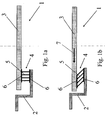
- FIG. 1a an embodiment of the composite component 1 according to the invention is shown schematically.
- a molding 2 e.g. a frame of a vehicle roof made of steel, and a molded part 3, e.g. a disc made of polycarbonate, are connected by means of a connecting element 4.
- the two mold parts 2, 3 have different coefficients of linear expansion.
- the connecting element 4 is made of elastic material, e.g. Thermoplastic polyurethane (TPU), and shear flexible deformable.
- TPU Thermoplastic polyurethane
- the connecting element 4 lamellar thrust elements 5, which are bendable when the temperature changes with respect to the longitudinal forces. Under tensile load, the lamellar Schublemente 5 are stable.
- the lamellar elements 5 are at their upper and lower ends, i. at the mold parts 2, 3 facing ends, connected to one another via end elements 6.
- the end elements 6 are each connected to one of the mold parts 2, 3.
- the deformation due to thermal expansion of a polycarbonate pane in a steel frame was calculated by means of a two-dimensional model of a motor vehicle roof module.
- the polycarbonate disc was adhered to a steel frame.
- the polycarbonate pane 3 was connected to a steel frame 2 by means of a connecting element 4 with 4 lamellar pushing elements 5.
- Table 1 summarizes the calculated deformation and stress values at a temperature difference of 100 K. ⁇ b> ⁇ u> Table 1 ⁇ / u> ⁇ /b> Type of connection Max. Deformation [mm] Max. Voltage [MPa] Gluing (comparative example) 38.8 1.7 Connecting element (exemplary embodiment) 0.4 0.06
- the deformation by thermal expansion of a polycarbonate disc in a steel frame was determined by calculation using a three-dimensional model of a motor vehicle roof module.
- the polycarbonate disc was adhered to a steel frame.
- the polycarbonate pane 3 was connected to a steel frame 2 by means of a connecting element 4 with 4 lamellar pushing elements 5.
- Table 2 summarizes the calculated maximum deformation values at a temperature difference of 100 K. ⁇ b> ⁇ u> Table 2 ⁇ / u> ⁇ /b> Type of connection Max.
Landscapes
- Engineering & Computer Science (AREA)
- Chemical & Material Sciences (AREA)
- Combustion & Propulsion (AREA)
- Transportation (AREA)
- Mechanical Engineering (AREA)
- Architecture (AREA)
- Structural Engineering (AREA)
- Body Structure For Vehicles (AREA)
- Connection Of Plates (AREA)
- Laminated Bodies (AREA)
- Springs (AREA)
- Compositions Of Macromolecular Compounds (AREA)
Abstract
Description
- Die Erfindung betrifft ein Verbundbauteil, wenigstens bestehend aus zwei Formteilen mit unterschiedlichen thermischen Längenausdehnungskoeffizienten, welche mittels wenigstens eines Verbindungselements aus einem elastischen Material verbunden sind.
- Bei Verbundbauteilen aus einem Metall-Formteil und einem Kunststoff-Formteil, welche miteinander verbunden sind, zeigt sich häufig das Problem, dass aufgrund der unterschiedlichen thermischen Längenausdehnungskoeffizienten der beiden Werkstoffe Spannungen oder Verformungen auftreten. Werden beispielsweise für die Verscheibung von Fahrzeugdächem anstelle von Glas Scheiben aus Polycarbonat eingesetzt, weisen Polycarbonatscheiben im Vergleich zu Glasscheiben eine wesentlich höhere Verformung bei Wärmebelastung durch die unterschiedlichen Längenausdehnungskoeffizienten von Polycarbonat zu Stahl auf. Die Scheiben aus Polycarbonat werden beispielsweise mittels Klebstoff mit dem Fahrzeugdach aus Stahl verbunden, während Glasscheiben üblicherweise mittels Klemmdichtungen oder Klebstoff befestigt werden. Wenn sich unter starker Erwärmung die Polycarbonatscheiben ausdehnen, kann der Klebstoff die Längenausdehnung nicht ausreichend ausgleichen, sodass die Scheiben verbeulen. Bei Glasscheiben besteht aufgrund der geringeren Unterschiede des Längenausdehnungskoeffizienten zum Stahl und der höheren Eigensteifigkeit im Vergleich zum Polycarbonat dieses Problem der Verformung nicht.
- DE 43 30 030 C offenbart eine Baueinheit zur Kraftübertragung in und zwischen fasertechnischen und anderen Bauteilen, das eine möglichst optimale Scherkrafteinleitung vom fasertechnischen Bauteil gewährleistet.
- Aufgabe der vorliegenden Erfindung ist es daher, ein Verbundelement, wenigstens bestehend aus zwei Formteilen mit unterschiedlichen thermischen Längenausdehnungskoeffizienten, insbesondere einem Formteil aus Metall und einem Formteil aus Kunststoff, bereitzustellen, bei dem die Formteile derart miteinander verbunden sind, dass ein Längenausgleich der beiden Formteile möglich ist. Dadurch sollen unerwünschte Verformungen der Formteile, insbesondere des Kunststoff-Formteils, aufgrund der unterschiedlichen thermischen Längenausdehnung der Formteile verhindert werden. Gleichzeitig sollen die auftretenden äußeren Kräfte, wie z.B. Windlast im Falle der Fahrzeugverscheibung, aufgenommen werden, sodass die Verformung durch mechanische Belastungen und das Eigenfrequenzverhalten nicht verschlechtert werden.
- Gegenstand der Erfindung ist ein Verbundbauteil wenigstens bestehend aus zwei Formteilen mit unterschiedlichen thermischen Längenausdehnungskoeffizienten, welche mittels wenigstens eines Verbindungselements aus einem elastischen Material verbunden sind, wobei das Verbindungselement wenigstens ein Schubelement aufweist, welches schubflexibel verformbar ist und ein Verhältnis von Höhe zu Dicke von 2 bis 60 aufweist.
- Das erfindungsgemäße Verbundbauteil besteht wenigstens aus zwei Formteilen, welche unterschiedliche thermische Längenausdehnungskoeffizienten besitzen. Der Unterschied der Längenausdehnungskoeffizienten beträgt bevorzugt mindestens 20·10-6 K-1 sowie bevorzugt maximal 100·10-6 K-1.
- Wenigstens eines der Formteile kann z.B. aus Metall, vorzugsweise aus Stahl, Aluminium, Magnesium, Kupfer, Titan und/oder einer Legierung dieser Metalle, sein. Besonders bevorzugt besteht eines der Formteile aus Stahl.
- Wenigstens eines der Formteile kann z.B. aus Kunststoff, vorzugsweise aus PC, PMMA, ABS, ASA, PA, PBT, PP oder Blends aus diesen Kunststoffen sein. Besonders bevorzugt besteht eines der Formteile aus Polycarbonat.
- Die Formteile können beliebige geometrische Formen aufweisen. Sie können z.B. Platten, Halbschalen oder Rahmenelemente sein. Vorzugsweise handelt es sich bei einem der Formteile um ein Fahrzeugdach aus Stahl mit einer Aussparung für eine Fensterscheibe und bei einem weiteren Formteil um ein Platte aus Polycarbonat zur Verscheibung des Fahrzeugdachs.
- Die Formteile sind mittels wenigstens eines Verbindungselements aus einem elastischen Material verbunden. Das elastische Material des Verbindungselements ist vorzugsweise ein Kunststoff, insbesondere Thermoplastisches Polyurethan (TPU), Thermoplastisches Elastomer (TPE), Kautschuk, unverstärktes Polyamid, PP und/oder PE.
- Das Verbindungselement weist wenigstens ein Schubelement auf, welches schubflexibel verformbar ist und ein Verhältnis von Höhe zu Dicke von 2 bis 60 aufweist. Höhe und Dicke des Schubelements beziehen sich auf den Ruhezustand, d.h. ohne angreifende Schubkraft. Dabei wird als Höhe des Schubelements die Ausdehnung zwischen den beiden Verbindungspunkten des Schubelements mit den Formteilen angesehen. Steht das Schubelement rechtwinklig zu den beiden Formteilen, so entspricht die Höhe des Schubelements im Wesentlichen dem Abstand zwischen den beiden Formteilen im Verbindungsbereich. Als Dicke wird die geringere der beiden senkrecht zur Höhe stehenden Ausdehnungen des Schubelements angesehen. Die Dicke erstreckt sich somit parallel zur Verschiebung der beiden Formteile zueinander, d.h. zur Richtung der angreifenden Schubkraft.
- Die Formteile können prinzipiell an beliebiger Stelle über das Verbindungselement miteinander verbunden sein, wobei sie in dem Verbindungsbereich einander überlappen. Sie können beispielsweise beispielsweise ganz oder teilweise übereinander angeordnet sein. Die Formteile können z.B. in jeweils einem Randbereich übereinander angeordnet sein, d.h. Randbereiche der beiden Formteile überlappen sich.
- In überlappenden Bereichen sorgt das Verbindungselement für eine schubflexible Verbindung der beiden Formteile, da das Verbindungselement erfindungsgemäß aus einem elastischen Material und schubflexibel verformbar ist mit einem Verhältnis von Höhe zu Dicke von 2 bis 60. Ein hohes Höhe zu Dicke Verhältnis des Schubelements ermöglicht im Vergleich zu einer Verbindung mittels Klebstoff eine höhere Schubflexibilität. Somit erlaubt das erfindungsgemäße Verbindungselement die unter Wärmebelastung unterschiedliche Längenausdehnung der beiden Formteile auszugleichen, ohne dass unerwünschte Verformungen, z.B. Beulen, der Formteile auftreten. Dies geschieht erfindungsgemäß durch eine Relativbewegung zwischen den beiden Formteilen mit verhältnismäßig geringem Kraftaufwand.
- Das Schubelement kann z.B. lamellenförmig oder stabförmig sein. Bei einem lamellenförmigen Schubelement entspricht die Dicke der Wanddicke des Schubelements. Bei einem stabförmigen Schubelement mit einem im Wesentlichen runden Querschnitt entspricht die Dicke des Schubelements dem Durchmesser des stabförmigen Schubelements. Weist ein stabförmiges Schubelement beispielsweise einen quadratischen Querschnitt auf, so entspricht die Dicke der Kantenlange quadratischen Querschnitts. Weitere regelmäßige oder unregelmäßige geometrische Formen sind möglich, sofern sie ein Verhältnis von Höhe zu Dicke von 2 bis 60 aufweisen. Ist das Verbindungselement aus mehreren Schubelementen aufgebaut, können die Schubelemente gleich oder verschieden sein.
- In einer ersten Ausführungsform weist das Verbindungselement lamellenförmige Schubelemente auf, welche in Schubrichtung flexibel verformbar sind, aber rechtwinklig dazu, d.h. in Richtung der Lamellen, Kräfte gut übertragen können. Die lamellenförmigen Elemente sind gegenüber den Längskräften, welche bei Temperaturänderung auftreten biegeweich, sodass eine Verschiebung der beiden Formteile relativ zueinander möglich ist. Dies verhindert unerwünschte Verformungen der Formteile aufgrund der unterschiedlichen Längenausdehnung. Diese Ausführungsform kann beispielsweise derart gestaltet sein, dass die lamellenförmigen Schubelemente aus elastischem Material über Endelemente miteinander verbunden sind, wobei die Endelemente jeweils an den oberen und unteren Enden der Schubelemente angeordnet sind. Als obere und untere Enden der Schubelemente werden die den Formteilen zugewandten Enden angesehen. Derartige Endelemente sind streifenförmig, plattenförmig o.dgl. Dabei ist jeweils ein Endelement mit jeweils einem der Formteile verbunden. Die Verbindung eines Endelements mit einem Formteil kann beispielsweise mittels Kleben, Schrauben, Nieten, Clinchen erfolgen.
- In dieser Ausführungsform kann das Verbindungselement neben der Verbindung der beiden Formteile vorteilhafterweise auch eine Dichtung zwischen den beiden Formteilen ermöglichen.
- In einer weiteren Ausführungsform weist das Verbindungselement stabförmige Schubelemente auf, welche schubflexibel verformbar sind. Ähnlich den lamellenförmigen Schubelementen erlauben die elastischen stabförmigen Elemente unter Schubspannung aufgrund von Wärmebelastung eine Verschiebung der beiden Formteile gegeneinander. Diese Ausführungsform kann beispielsweise derart gestaltet sein, dass die stabförmigen Schubelemente an ihren Enden über Endelemente miteinander verbunden sind. Dabei ist ein Endelement wiederum jeweils mit einem der Formteile verbunden. Die Verbindung eines Endelements mit einem Formteil kann beispielsweise mittels Kleben, Schrauben, Nieten, Clinchen erfolgen.
- Lamellenförmige Elemente und stabförmige Elemente können auch in Kombination auftreten. Ebenso sind beliebige Abwandlungen der Lamellenform oder der Stabform möglich, soweit die Elemente eine ausreichende Stabilität sowie eine schubflexible Verbindung erlauben. Je nach Form und Material der Formteile muss das Verbindungselement eine ausreichende Stabilität zur Aufnahme der äußeren Kräfte (z.B. Windlast, Schwingungen) aufweisen. Zur Erhöhung der Stabilität können beispielsweise eine höhere Anzahl von Schubelementen vorgesehen sein. Auch die Dicke der Schubelemente bestimmen die Stabilität. Die Dicke kann beispielsweise auch über die Höhe der Elemente variieren.
- Die Anzahl der Schubelemente, insbesondere die Anzahl von lamellenförmigen Schubelementen, beträgt bevorzugt mindestens 2 sowie bevorzugt maximal 8. Der Abstand der beiden zu verbindenden Formteile, und damit die Höhe eines Schubelements, beträgt bevorzugt mindestens 5 mm sowie bevorzugt maximal 30 mm. Die Dicke eines Schubelements, insbesondere eines lamellenförmigen Schubelements, beträgt bevorzugt mindestens 0,5 mm sowie bevorzugt maximal 2,5 mm. Die Dicke eines Endelementes beträgt bevorzugt mindestens 0,5 mm sowie bevorzugt maximal 4 mm. Ist das Verbindungselement neben Schubelementen aus Endelementen zusammengesetzt, reduziert sich die Höhe der Schubelemente entsprechend um die Dicke der Endelemente. Die Höhe der Schubelemente und die Dicke der Endelemente ergeben zusammen den Abstand der beiden Formteile zueinander, d.h. die Höhe des gesamten Verbindungselements.
- Das Verbindungselement des erfindungsgemäßen Verbundbauteils kann beispielsweise mittels Extrusion hergestellt werden. Das Verbindungselement kann aber auch aus verschiedenen spritzgegossenen und/oder extrudierten Einzelteilen, die mittels eines Schweiß- oder Klebeprozesses verbunden werden, hergestellt werden.
- Eine mögliche Anwendung des erfindungsgemäßen Verbundbauteils liegt in der Verscheibung von Fahrzeugdächern. Hierbei bildet das Fahrzeugdach aus Stahl eines der Formteile und die Scheibe aus Polycarbonat ein zweites Formteil. Die Polycarbonatscheibe ist in dem Fahrzeugdach in einen Rahmen eingelegt. In einem Randbereich, in dem sich der Stahlrahmen und die Polycarbonatscheibe überlappen, sind die beiden Formteile mittels des erfindungsgemäßen, schubflexibel verformbaren Verbindungselements aus elastischem Material, insbesondere Thermoplastisches Polyurethan (TPU), Thermoplastisches Elastomer (TPE), Kautschuk, verbunden. Bevorzugt ist an allen vier Außenkanten der Polycarbonatscheibe jeweils ein Verbindungselement vorgesehen.
- Nachfolgend wird die Erfindung anhand der beigefügten Zeichnungen näher erläutert. Es zeigen
- Figur 1a
- eine schematische Darstellung einer Ausführungsform des erfindungsgemäßen Verbindungselements zur Verbindung zweier Formteile
- Figur 1b
- eine schematische Darstellung des Verbindungselements aus Fig. 1a unter Schubspannung.
- In Figur 1a ist eine Ausführungsform des erfindungsgemäßen Verbundbauteils 1 schematisch dargestellt. Ein Formteil 2, z.B. ein Rahmen eines Fahrzeugdachs aus Stahl, und ein Formteil 3, z.B. eine Scheibe aus Polycarbonat, sind mittels eines Verbindungselements 4 verbunden. Die beiden Formteile 2, 3 besitzen unterschiedliche Längenausdehnungskoeffizienten. Das Verbindungselement 4 ist aus elastischem Material, z.B. Thermoplastisches Polyurethan (TPU), und schubflexibel verformbar. In der dargestellten Ausführungsform weist das Verbindungselement 4 lamellenförmige Schubelemente 5 auf, die bei Temperaturänderung gegenüber den Längskräften biegeweich sind. Unter Zugbelastung sind die lamellenförmigen Schublemente 5 stabil. Die lamellenförmigen Elemente 5 sind an ihren oberen und unteren Enden, d.h. an den der Formteile 2, 3 zugewandten Enden, über Endelemente 6 miteinander verbunden. Die Endelemente 6 sind jeweils mit einem der Formteile 2, 3 verbunden.
- Wie in Figur 1b schematisch dargestellt, treten unter Temperaturänderung Schubkräfte auf, die eine Verschiebung (durch den Pfeil 7 markiert) der beiden Formteile 2, 3 gegeneinander hervorrufen, ohne dass unerwünschte Verformungen der Formteile 2, 3 auftreten.
- Die Verformung durch Wärmedehnung einer Polycarbonatscheibe in einem Stahlrahmen wurde rechnerisch anhand eines zweidimensionalen Modells eines Kraftfahrzeug-Dachmoduls ermittelt. In dem Vergleichsbeispiel war die Polycarbonatscheibe auf einen Stahlrahmen aufgeklebt. In dem Ausführungsbeispiel war, ähnlich wie in Figur 1a dargestellt, die Polycarbonatscheibe 3 mit einem Stahlrahmen 2 mittels eines Verbindungselements 4 mit 4 lamellenförmigen Schubelementen 5 verbunden. Die nachfolgende Tabelle 1 fasst die rechnerisch ermittelten Verformungs- und Spannungswerte bei einer Temperaturdifferenz von 100 K zusammen.
Tabelle 1 Art der Verbindung max. Verformung [mm] max. Spannung [MPa] Kleben (Vergleichsbeispiel) 38,8 1,7 Verbindungselement (Ausführungsbeispiel) 0,4 0,06 - Die Verformung durch Wärmedehnung einer Polycarbonatscheibe in einem Stahlrahmen wurde rechnerisch anhand eines dreidimensionalen Modells eines Kraftfahrzeug-Dachmoduls ermittelt. In dem Vergleichsbeispiel war die Polycarbonatscheibe auf einen Stahlrahmen aufgeklebt. In dem Ausführungsbeispiel war, ähnlich wie in Figur 1a dargestellt, die Polycarbonatscheibe 3 mit einem Stahlrahmen 2 mittels eines Verbindungselements 4 mit 4 lamellenförmigen Schubelementen 5 verbunden. Die nachfolgende Tabelle 2 fasst die rechnerisch ermittelten maximalen Verformungswerte bei einer Temperaturdifferenz von 100 K zusammen.
Tabelle 2 Art der Verbindung max. Verformung [mm] Kleben (Vergleichsbeispiel) 9,7 Verbindungselement (Ausführungsbeispiel) 2,3
Claims (6)
- Verbundbauteil wenigstens bestehend aus zwei Formteilen mit unterschiedlichen thermischen Längenausdehnungskoeffizienten, welche mittels wenigstens eines Verbindungselements aus einem elastischen Material verbunden sind, dadurch gekennzeichnet, dass das Verbindungselement wenigstens ein Schubelement aufweist, welches schubflexibel verformbar ist und ein Verhältnis von Höhe zu Dicke von 2 bis 60 aufweist.
- Verbundbauteil nach Anspruch 1, dadurch gekennzeichnet, dass das Schubelement lamellenförmig ist.
- Verbundbauteil nach Anspruch 1, dadurch gekennzeichnet, dass das Schubelement stabförmig ist.
- Verbundbauteil nach einem der Ansprüche 1-3, dadurch gekennzeichnet, dass das elastische Material ein Kunststoff, insbesondere Thermoplastisches Polyurethan, Thermoplastisches Elastomer, Kautschuk, unverstärktes Polyamid, PP und/oder PE, ist.
- Verbundbauteil nach einem der Ansprüche 1-4, dadurch gekennzeichnet, dass ein Formteil aus einem Metall, insbesondere Stahl, Aluminium, Magnesium, Kupfer, Titan und/oder einer Legierung dieser Metalle, ist.
- Verbundbauteil nach einem der Ansprüche 1-5, dadurch gekennzeichnet, dass ein Formteil aus Kunststoff, insbesondere aus Polycarbonat, PMMA, ABS, ASA, PA, PBT, PP oder Blends aus diesen Kunststoffen, ist.
Applications Claiming Priority (1)
| Application Number | Priority Date | Filing Date | Title |
|---|---|---|---|
| DE102004041685A DE102004041685B3 (de) | 2004-08-26 | 2004-08-26 | Verbundbauteil |
Publications (2)
| Publication Number | Publication Date |
|---|---|
| EP1632681A2 true EP1632681A2 (de) | 2006-03-08 |
| EP1632681A3 EP1632681A3 (de) | 2006-09-06 |
Family
ID=35432821
Family Applications (1)
| Application Number | Title | Priority Date | Filing Date |
|---|---|---|---|
| EP05017682A Withdrawn EP1632681A3 (de) | 2004-08-26 | 2005-08-13 | Verbundbauteil |
Country Status (6)
| Country | Link |
|---|---|
| US (1) | US7622177B2 (de) |
| EP (1) | EP1632681A3 (de) |
| JP (1) | JP5273899B2 (de) |
| KR (1) | KR101322134B1 (de) |
| CN (1) | CN1740500B (de) |
| DE (1) | DE102004041685B3 (de) |
Cited By (1)
| Publication number | Priority date | Publication date | Assignee | Title |
|---|---|---|---|---|
| EP2588346B1 (de) * | 2010-07-02 | 2016-09-14 | Johnson Controls Interiors GmbH & Co. KG | Fahrzeuginnenausstattungsteil insbesondere türinnenverkleidung |
Families Citing this family (10)
| Publication number | Priority date | Publication date | Assignee | Title |
|---|---|---|---|---|
| WO2008002222A1 (en) * | 2006-06-30 | 2008-01-03 | Volvo Lastvagnar Ab | A panel mounting device and a panel mounting arrangement for attaching a panel onto a vehicle |
| DE102007050159A1 (de) * | 2007-10-19 | 2009-04-23 | Rolls-Royce Deutschland Ltd & Co Kg | Befestigungselement |
| US7828373B2 (en) * | 2008-09-24 | 2010-11-09 | Ford Global Technologies, Llc | Polycarbonate panel assembly for a vehicle |
| US9290261B2 (en) * | 2011-06-09 | 2016-03-22 | United Technologies Corporation | Method and assembly for attaching components |
| US10059431B2 (en) | 2011-06-09 | 2018-08-28 | United Technologies Corporation | Method and apparatus for attaching components having dissimilar rates of thermal expansion |
| JP2013010436A (ja) * | 2011-06-29 | 2013-01-17 | Toyota Auto Body Co Ltd | 自動車の車体に対する樹脂ガラスの接着構造 |
| DE202014004541U1 (de) * | 2014-05-28 | 2015-08-31 | GM Global Technology Operations, LLC (n.d. Ges. d. Staates Delaware) | Schwingungsabsorber für ein Kraftfahrzeug, insbesondere den Dachrahmen einer Fahrzeugkarosserie |
| FR3027580B1 (fr) * | 2014-10-24 | 2016-11-04 | Renault Sas | Gamme d'au moins deux types de vehicule automobile comprenant un pavillon en tole ou un pavillon en verre |
| JP7200903B2 (ja) * | 2019-10-09 | 2023-01-10 | 株式会社豊田自動織機 | 車両用接合構造体 |
| DE102023129866B3 (de) | 2023-10-30 | 2024-09-26 | Dr. Ing. H.C. F. Porsche Aktiengesellschaft | Verbundbauteil und Kraftfahrzeug |
Family Cites Families (20)
| Publication number | Priority date | Publication date | Assignee | Title |
|---|---|---|---|---|
| US4113905A (en) * | 1977-01-06 | 1978-09-12 | Gerald Kessler | D.i.g. foam spacer |
| US4272578A (en) * | 1979-05-31 | 1981-06-09 | Schegerin Robert J F | Ski apparatus |
| JPS62194980A (ja) * | 1986-02-19 | 1987-08-27 | Mazda Motor Corp | 自動車用プラスチツクル−フの取付構造 |
| JPH0520580Y2 (de) * | 1987-08-28 | 1993-05-27 | ||
| JPH06122837A (ja) * | 1991-12-27 | 1994-05-06 | Kuraray Co Ltd | 熱硬化型被覆用組成物 |
| JP3263697B2 (ja) * | 1992-01-10 | 2002-03-04 | 日産自動車株式会社 | 車両用サンルーフリッド構造 |
| JPH06312620A (ja) * | 1993-04-28 | 1994-11-08 | Toyoda Gosei Co Ltd | 自動車用ウインドモール |
| DE4330030C1 (de) * | 1993-09-06 | 1995-03-09 | Forschungskuratorium Maschinen | Baueinheit zur Kraftübertragung in und zwischen fasertechnischen und anderen Bauteilen und Verfahren zu seiner Herstellung |
| JP3323622B2 (ja) | 1994-01-12 | 2002-09-09 | 株式会社フジタ | 建築構造物の制振装置 |
| JPH0858392A (ja) * | 1994-08-26 | 1996-03-05 | Toyoda Gosei Co Ltd | サンルーフ |
| JPH0886044A (ja) * | 1994-09-20 | 1996-04-02 | Takenaka Komuten Co Ltd | 反り変形しない建築仕上用パネル |
| JPH09220793A (ja) * | 1996-02-16 | 1997-08-26 | Okura Ind Co Ltd | 積層化粧板 |
| DE19814275B4 (de) * | 1998-03-31 | 2008-11-13 | Jost-Werke Gmbh | Sattelkupplung |
| JP3957875B2 (ja) * | 1998-06-02 | 2007-08-15 | 株式会社アルティア橋本 | 窓組立体及びその組み立て方法 |
| JP2000096750A (ja) * | 1998-07-23 | 2000-04-04 | Sekisui Chem Co Ltd | バルコニー面構造体及びその製造方法 |
| JP2001018644A (ja) * | 1999-07-02 | 2001-01-23 | Komatsu Ltd | 車両の天窓透視部材の取付構造 |
| DE19943772C1 (de) * | 1999-09-13 | 2001-01-18 | Webasto Dachsysteme Gmbh | Fahrzeugdach mit unter Spiel gelagerter Führungsschiene für öffnungsfähiges Dachteil |
| DE10035912C2 (de) * | 2000-07-21 | 2003-05-15 | Webasto Vehicle Sys Int Gmbh | Kunststoffdeckel für Fahrzeuge |
| US6458301B1 (en) * | 2001-08-27 | 2002-10-01 | Schlegel Corporation | Method for forming weatherseals from an interchangeable insert die assembly |
| KR100519234B1 (ko) * | 2002-11-22 | 2005-10-06 | 한국건설기술연구원 | 프리캐스트 교량 바닥판과 거더의 연결구조 및 이를이용한 교량시공방법 |
-
2004
- 2004-08-26 DE DE102004041685A patent/DE102004041685B3/de not_active Expired - Fee Related
-
2005
- 2005-08-13 EP EP05017682A patent/EP1632681A3/de not_active Withdrawn
- 2005-08-23 US US11/210,188 patent/US7622177B2/en active Active
- 2005-08-24 KR KR1020050077679A patent/KR101322134B1/ko not_active Expired - Fee Related
- 2005-08-25 JP JP2005243782A patent/JP5273899B2/ja not_active Expired - Fee Related
- 2005-08-26 CN CN200510099459.2A patent/CN1740500B/zh not_active Expired - Fee Related
Cited By (1)
| Publication number | Priority date | Publication date | Assignee | Title |
|---|---|---|---|---|
| EP2588346B1 (de) * | 2010-07-02 | 2016-09-14 | Johnson Controls Interiors GmbH & Co. KG | Fahrzeuginnenausstattungsteil insbesondere türinnenverkleidung |
Also Published As
| Publication number | Publication date |
|---|---|
| US7622177B2 (en) | 2009-11-24 |
| DE102004041685B3 (de) | 2006-05-04 |
| JP5273899B2 (ja) | 2013-08-28 |
| EP1632681A3 (de) | 2006-09-06 |
| CN1740500B (zh) | 2014-09-03 |
| CN1740500A (zh) | 2006-03-01 |
| KR101322134B1 (ko) | 2013-10-25 |
| JP2006112621A (ja) | 2006-04-27 |
| KR20060050599A (ko) | 2006-05-19 |
| US20060046039A1 (en) | 2006-03-02 |
Similar Documents
| Publication | Publication Date | Title |
|---|---|---|
| EP2018999B1 (de) | Energieabsorber zur Verwendung als Aufprallschutz in einem Kraftfahrzeug | |
| DE102012023653A1 (de) | Kraftfahrzeugkarosserie mit Leichtbauteil | |
| DE60009227T2 (de) | Halterung für Fensterheber | |
| DE102004041685B3 (de) | Verbundbauteil | |
| EP1342625A1 (de) | Stossstange mit Halterungen | |
| EP2332810B1 (de) | Karosserie eines Kraftfahrzeugs | |
| EP1690780A2 (de) | Dachanordnung für Kraftfahrzeuge | |
| DE202014009832U1 (de) | Fronthaube für ein Kraftfahrzeug | |
| DE3241906A1 (de) | Fahrzeugkarosserie mit zumindest einer daran durch ein haftmittel befestigten zier- oder schutzleiste | |
| DE202007011147U1 (de) | Durchsichtiges Fahrzeugpaneel | |
| EP1488986B1 (de) | Kraftfahrzeug mit einer Verbindungsanordnung im Dachbereich | |
| DE102005011834B4 (de) | Seitlicher Dachrahmen für ein Kraftfahrzeug | |
| DE102005017981B4 (de) | Säule einer Karosserie eines Kraftfahrzeugs | |
| DE202008007706U1 (de) | Dichtungsprofil | |
| DE10239919A1 (de) | Schutzvorrichtung für ein Kraftfahrzeug | |
| DE102005039500B4 (de) | Verfahren zur Herstellung von Verbundbauteilen | |
| DE102017127935B4 (de) | Blattfeder mit einem Federkörper aus einem Faserverbundwerkstoff und einer Mittenklemmung | |
| DE19829354C1 (de) | Unterlegscheibe sowie Bauteilverbindung mit einer Unterlegscheibe | |
| EP1233136A1 (de) | Kunststoff-Abstandshalterrahmen und Verfahren zu seiner Herstellung | |
| EP0755838B1 (de) | Gerippestruktur mit Türrahmen und Wandelementen | |
| EP4275995B1 (de) | Kraftfahrzeug-dachkonstruktion eines nutzfahrzeugs mit mehreren dach-querträgern und einer dachverkleidung sowie montageverfahren | |
| DE10356465B3 (de) | Kraftfahrzeugtür mit einem Seitenaufprallträger und einem Türkörper | |
| DE10255999A1 (de) | Längsgesickter Dachlängsträger für ein Kraftfahrzeug | |
| DE102005033351A1 (de) | Herstellung von Kunststoffbaugruppen mit Dehnungselementen | |
| DE102014003199A1 (de) | Fronthaube für ein Kraftfahrzeug |
Legal Events
| Date | Code | Title | Description |
|---|---|---|---|
| PUAI | Public reference made under article 153(3) epc to a published international application that has entered the european phase |
Free format text: ORIGINAL CODE: 0009012 |
|
| AK | Designated contracting states |
Kind code of ref document: A2 Designated state(s): AT BE BG CH CY CZ DE DK EE ES FI FR GB GR HU IE IS IT LI LT LU LV MC NL PL PT RO SE SI SK TR |
|
| AX | Request for extension of the european patent |
Extension state: AL BA HR MK YU |
|
| PUAL | Search report despatched |
Free format text: ORIGINAL CODE: 0009013 |
|
| AK | Designated contracting states |
Kind code of ref document: A3 Designated state(s): AT BE BG CH CY CZ DE DK EE ES FI FR GB GR HU IE IS IT LI LT LU LV MC NL PL PT RO SE SI SK TR |
|
| AX | Request for extension of the european patent |
Extension state: AL BA HR MK YU |
|
| 17P | Request for examination filed |
Effective date: 20070306 |
|
| 17Q | First examination report despatched |
Effective date: 20070404 |
|
| AKX | Designation fees paid |
Designated state(s): AT BE BG CH CY CZ DE DK EE ES FI FR GB GR HU IE IS IT LI LT LU LV MC NL PL PT RO SE SI SK TR |
|
| STAA | Information on the status of an ep patent application or granted ep patent |
Free format text: STATUS: THE APPLICATION IS DEEMED TO BE WITHDRAWN |
|
| 18D | Application deemed to be withdrawn |
Effective date: 20070815 |