EP1632652B1 - Moteur à combustion interne avec au moins un arbre à cames avec au moins un conduit d'aération - Google Patents
Moteur à combustion interne avec au moins un arbre à cames avec au moins un conduit d'aération Download PDFInfo
- Publication number
- EP1632652B1 EP1632652B1 EP05450141A EP05450141A EP1632652B1 EP 1632652 B1 EP1632652 B1 EP 1632652B1 EP 05450141 A EP05450141 A EP 05450141A EP 05450141 A EP05450141 A EP 05450141A EP 1632652 B1 EP1632652 B1 EP 1632652B1
- Authority
- EP
- European Patent Office
- Prior art keywords
- internal combustion
- combustion engine
- camshaft
- engine according
- flyweight
- Prior art date
- Legal status (The legal status is an assumption and is not a legal conclusion. Google has not performed a legal analysis and makes no representation as to the accuracy of the status listed.)
- Expired - Lifetime
Links
Images

Classifications
-
- F—MECHANICAL ENGINEERING; LIGHTING; HEATING; WEAPONS; BLASTING
- F01—MACHINES OR ENGINES IN GENERAL; ENGINE PLANTS IN GENERAL; STEAM ENGINES
- F01L—CYCLICALLY OPERATING VALVES FOR MACHINES OR ENGINES
- F01L1/00—Valve-gear or valve arrangements, e.g. lift-valve gear
- F01L1/02—Valve drive
- F01L1/04—Valve drive by means of cams, camshafts, cam discs, eccentrics or the like
- F01L1/047—Camshafts
-
- B—PERFORMING OPERATIONS; TRANSPORTING
- B64—AIRCRAFT; AVIATION; COSMONAUTICS
- B64C—AEROPLANES; HELICOPTERS
- B64C1/00—Fuselages; Constructional features common to fuselages, wings, stabilising surfaces or the like
- B64C1/0009—Aerodynamic aspects
-
- B—PERFORMING OPERATIONS; TRANSPORTING
- B64—AIRCRAFT; AVIATION; COSMONAUTICS
- B64C—AEROPLANES; HELICOPTERS
- B64C1/00—Fuselages; Constructional features common to fuselages, wings, stabilising surfaces or the like
- B64C1/06—Frames; Stringers; Longerons ; Fuselage sections
- B64C1/064—Stringers; Longerons
-
- F—MECHANICAL ENGINEERING; LIGHTING; HEATING; WEAPONS; BLASTING
- F01—MACHINES OR ENGINES IN GENERAL; ENGINE PLANTS IN GENERAL; STEAM ENGINES
- F01M—LUBRICATING OF MACHINES OR ENGINES IN GENERAL; LUBRICATING INTERNAL COMBUSTION ENGINES; CRANKCASE VENTILATING
- F01M13/00—Crankcase ventilating or breathing
- F01M13/04—Crankcase ventilating or breathing having means for purifying air before leaving crankcase, e.g. removing oil
-
- F—MECHANICAL ENGINEERING; LIGHTING; HEATING; WEAPONS; BLASTING
- F01—MACHINES OR ENGINES IN GENERAL; ENGINE PLANTS IN GENERAL; STEAM ENGINES
- F01M—LUBRICATING OF MACHINES OR ENGINES IN GENERAL; LUBRICATING INTERNAL COMBUSTION ENGINES; CRANKCASE VENTILATING
- F01M13/00—Crankcase ventilating or breathing
- F01M13/04—Crankcase ventilating or breathing having means for purifying air before leaving crankcase, e.g. removing oil
- F01M2013/0422—Separating oil and gas with a centrifuge device
Definitions
- the invention relates to an internal combustion engine having at least one camshaft having at least one venting channel for venting a camshaft housing.
- WO 99/02824 shows a working device driven by an internal combustion engine, wherein the crankcase is connected to the camshaft housing via a venting line.
- the camshaft housing has a vent opening with an oil separator.
- US 4,651,704 A and US 6,502,565 B2 describe internal combustion engines with hollow camshafts, wherein the vent channel for venting the camshaft housing is disposed within the camshaft.
- Decompression means serve to reduce the compression pressure in internal combustion engines during the star phase in order to reduce the starting power to be applied.
- JP 2002-122012 A and US 5,711,264 A disclose decompression devices, each having a centrifugal weight, which can rotate a decompression element arranged in a recess of a cam. At low speed, a projection of the decompression element projects beyond the base circle of the cam, so that a decompression of the cylinder takes place. At a higher speed, a deflection causes the projection of the decompression element to be completely rotated within the base circle.
- the object of the invention is to avoid the disadvantages mentioned and to prevent oil leakage when the internal combustion engine turned off in the simplest possible way.
- vent channel is closed by a flyweight-controlled closure member at engine standstill.
- the shut-off member is integrated in a vorzugseise at least one flyweight having decompression device. It is particularly advantageous if the centrifugal weight forms a closure element of the shut-off member, which closes a preferably camshaft-fixed venting channel at standstill of the camshaft, wherein preferably the closable by Abschaltorgan portion of the Enttrelyungskanasl is arranged radially with respect to the camshaft axis.
- the centrifugal weight can advantageously cooperate with a decompression element of the decompression device in the region of the base circle of a cam in such a way that the decompression element projects beyond the base circle when the camshaft is at a standstill.
- the closable by the Abschaltorgan portion of the vent passage is formed in a fixedly connected to the camshaft steering wheel.
- the centrifugal weight is rotatably mounted on the steering wheel.
- the decompression element has a rotatably mounted in a recess of the cam pin, wherein the axis of rotation of the pin is approximately parallel to the camshaft axis, and wherein the pin in cross-section the shape of a circle segment with an opening angle> 180 ° , preferably between 200 ° and 240 °.
- the pin is rotatable by the flyweight, preferably with the pin an actuating lever is connected to which the flyweight attacks, preferably flyweight and operating lever via a preferably in a slot or a Fork guided actuating pin are interconnected.
- an elastic Seal element is arranged, which is preferably formed by a rubber coating on the closure part and / or around the opening of the ventilation channel.
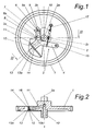
- a decompression device 3 is arranged at the steering wheel 1 of a camshaft 2, a decompression device 3 is arranged.
- the decompression device 3 has a flyweight 4 designed as a lever, which is mounted eccentrically on the steering wheel 1 about an axis 15 so as to be rotatable.
- the steering wheel 1 may be a pulley or a gear.
- the centrifugal weight 4 engages with its fork-like lever end 5 on an actuating pin 6 of an actuating lever 7, which is mounted by means of a pin 8 in a recess 9 of the cam 2b of the camshaft 2 pivotally.
- the actuating pin 6 is guided in the fork 5a of the lever end 5.
- the axis of rotation 8a of the pin 8 is arranged approximately parallel to the crankshaft axis 2a.
- the pin 8 has in cross-section the shape of a circular segment with an opening angle ⁇ > 180 °, for example between 200 ° and 240 °, as can be seen in Fig. 5, and forms the actual, a Dekompressionshub a gas exchange valve causing decompression element 3a.
- the flyweight 4 is brought by the return spring 17 in its drawn rest position, wherein the pin 8 is rotated so that a portion of the pin 8 projects beyond the base circle 2c of the cam 2b. If the internal combustion engine is put into operation, then the centrifugal weight 4 revolving with the camshaft 2 is deflected outward against the force of the restoring spring 17, whereby the journal is rotated into the position shown in FIG. 3, so that the journal 8 is entirely within the Base circle 2c comes to rest, creating an additional Exception of the outlet valve in the area of the base circle 2c is avoided.
- the camshaft 2 is hollow in the embodiment and has a, continuing in the steering wheel 1, axial venting channel 10, which is in communication with a radial venting channel 11 in the region of the steering wheel 1.
- the opening 12 of the radial venting channel 11 is closed by a closure member 13 in the rest position of the internal combustion engine, wherein the closure member 13 is actuated automatically in dependence on the rotational speed of the camshaft 2.
- the closure member 13 is formed as part of the decompression device 3. It is particularly advantageous if a closure element 13a of the closure member 13 is formed integrally with the flyweight 4 and is formed in the concrete embodiment by an angled lever portion 14 of the flyweight 4.
- the closure element 13a is pressed in the rest position of the centrifugal weight 4 against the opening 12 of the radial venting channel 11, as can be seen in Fig. 1.
- the closure element 13a is deflected by the flyweight 4, wherein the opening 12 of the radial venting channel 11 is released, as shown in FIG. 3.
- a sealing element 16 may be arranged in the region of the valve seat 13b of the closure member 13.
- the sealing element 16 may be formed by a vulcanized rubber coating on the closure part 13a or around the opening 12.
- closure member 13 is integrated into the decompression device 3, parts can be saved and a very compact design can be achieved.
- the closure member 13 the parked internal combustion engine can be transported in any position without leaking oil from the vent passage 10, 11.
Landscapes
- Engineering & Computer Science (AREA)
- Mechanical Engineering (AREA)
- General Engineering & Computer Science (AREA)
- Aviation & Aerospace Engineering (AREA)
- Physics & Mathematics (AREA)
- Fluid Mechanics (AREA)
- Valve Device For Special Equipments (AREA)
- Valve-Gear Or Valve Arrangements (AREA)
Claims (12)
- Moteur à combustion interne comportant au moins un arbre à cames (2) avec au moins un canal d'aération (10, 11) pour ventiler le carter d'arbre à cames,
caractérisé en ce que
le canal d'aération (11) est fermé à l'arrêt du moteur par un organe de fermeture (13) commandé par une masselotte centrifuge. - Moteur à combustion interne selon la revendication 1,
caractérisé en ce que
l'organe de fermeture (13) est intégré dans une installation de décompression (3) comportant au moins une masselotte centrifuge (4). - Moteur à combustion interne selon la revendication 1 ou 2,
caractérisé en ce que
la masselotte centrifuge (4) forme un élément de fermeture (13a) de l'organe de fermeture (13) qui, à l'arrêt de l'arbre à cames (2), ferme un canal d'aération (11), de préférence solidaire de l'arbre à cames. - Moteur à combustion interne selon la revendication 2 ou 3,
caractérisé en ce que
la masselotte centrifuge (4) coopère avec un élément de décompression (3a) au niveau du cercle primitif (2c) d'une came (2b) pour qu'à l'arrêt de l'arbre à cames (2); l'élément de décompression (3a) dépasse du cercle primitif (2c). - Moteur à combustion interne selon l'une des revendications 1 à 4,
caractérisé en ce que
le segment du canal d'aération (11) fermé par l'organe de fermeture (13) est installé radialement par rapport à l'axe de l'arbre à cames (2a). - Moteur à combustion interne selon l'une des revendications 1 à 5,
caractérisé en ce que
le segment du canal d'aération (11) fermé par l'organe d'obturation (13) est réalisé dans une roue de commande (1) solidaire de l'arbre à cames (2). - Moteur à combustion interne selon l'une des revendications 1 à 6,
caractérisé en ce que
la masselotte centrifuge (4) est montée à rotation sur la roue de commande (1). - Moteur à combustion interne selon l'une des revendications 4 à 7,
caractérisé en ce que
l'élément de décompression (3a) comporte un tourillon (8) tournant dans une cavité de la came (2b) et l'axe de rotation (8a) du tourillon (8) est sensiblement parallèle à l'axe de l'arbre à cames (2a). - Moteur à combustion interne selon la revendication 8,
caractérisé en ce que
le tourillon (8) a en coupe la forme d'un segment de cercle avec un angle d'ouverture (α) > 180° compris de préférence entre 200° et 240°. - Moteur à combustion interne selon la revendication 8 ou 9,
caractérisé en ce que
le tourillon (8) peut être tourné par la masselotte centrifuge (4) et un levier de manoeuvre (7) est de préférence relié au tourillon (8), la masselotte centrifuge (4) agissant sur ce levier. - Moteur à combustion interne selon la revendication 10,
caractérisé en ce que
la masselotte centrifuge (4) et le levier d'actionnement (7) sont reliés par une broche d'actionnement (6) guidée de préférence dans un trou oblong ou une fourchette (5a). - Moteur à combustion interne selon l'une des revendications 1 à 11,
caractérisé par
un élément d'étanchéité élastique (16) au niveau du siège de soupape (13b) de l'organe de fermeture (13), cet élément d'étanchéité étant formé de préférence par du caoutchouc prévu sur la pièce de fermeture (13a) et/ ou autour de l'ouverture (12) du canal d'aération (11).
Applications Claiming Priority (1)
| Application Number | Priority Date | Filing Date | Title |
|---|---|---|---|
| AT0147004A AT501031B1 (de) | 2004-09-02 | 2004-09-02 | Brennkraftmaschine mit zumindest einer mindestens einen entlüftungskanal aufweisenden nockenwelle |
Publications (2)
| Publication Number | Publication Date |
|---|---|
| EP1632652A1 EP1632652A1 (fr) | 2006-03-08 |
| EP1632652B1 true EP1632652B1 (fr) | 2007-03-14 |
Family
ID=35355239
Family Applications (1)
| Application Number | Title | Priority Date | Filing Date |
|---|---|---|---|
| EP05450141A Expired - Lifetime EP1632652B1 (fr) | 2004-09-02 | 2005-08-25 | Moteur à combustion interne avec au moins un arbre à cames avec au moins un conduit d'aération |
Country Status (3)
| Country | Link |
|---|---|
| EP (1) | EP1632652B1 (fr) |
| AT (2) | AT501031B1 (fr) |
| DE (1) | DE502005000474D1 (fr) |
Families Citing this family (1)
| Publication number | Priority date | Publication date | Assignee | Title |
|---|---|---|---|---|
| US20100006076A1 (en) * | 2008-07-08 | 2010-01-14 | Mavinahally Nagesh S | Breather System for a Four Stroke Engine |
Family Cites Families (11)
| Publication number | Priority date | Publication date | Assignee | Title |
|---|---|---|---|---|
| JPS61175213A (ja) * | 1985-01-30 | 1986-08-06 | Honda Motor Co Ltd | エンジンにおけるカムケ−スのブリ−ザ装置 |
| JPH03160107A (ja) * | 1989-11-15 | 1991-07-10 | Honda Motor Co Ltd | 頭上弁型エンジンにおけるブリーザ装置 |
| CZ285909B6 (cs) * | 1996-04-09 | 1999-11-17 | Motor Jikov A. S. | Dekompresní zařízení spalovacího motoru |
| AU3721197A (en) * | 1997-07-07 | 1999-02-08 | Ryobi North America, Inc. | Multi-position operable four-cycle engine |
| DE19803872C2 (de) * | 1998-01-31 | 2001-05-10 | Daimler Chrysler Ag | Entlüfungsvorrichtung für ein Kurbelgehäuse einer Brennkraftmaschine |
| DE19824041A1 (de) * | 1998-05-29 | 1999-12-02 | Stihl Maschf Andreas | Verbrennungsmotor |
| DE19931740C2 (de) * | 1999-07-08 | 2001-06-13 | Daimler Chrysler Ag | Hubkolbenbrennkraftmaschine mit einer Nockenwelle |
| DE19945948B4 (de) * | 1999-09-24 | 2004-04-08 | Ktm Sportmotorcycle Ag | Einzylinder-Verbrennungsmotor |
| AU2001290604A1 (en) * | 2000-09-01 | 2002-03-13 | Bombardier Inc. | Continuously variable transmission for an internal combustion engine |
| JP2002122012A (ja) * | 2000-10-13 | 2002-04-26 | Fuji Heavy Ind Ltd | エンジンのデコンプ装置 |
| US6584964B1 (en) * | 2002-08-13 | 2003-07-01 | Briggs & Stratton Corporation | Engine having a centrifugal oil separator |
-
2004
- 2004-09-02 AT AT0147004A patent/AT501031B1/de not_active IP Right Cessation
-
2005
- 2005-08-25 AT AT05450141T patent/ATE356922T1/de not_active IP Right Cessation
- 2005-08-25 EP EP05450141A patent/EP1632652B1/fr not_active Expired - Lifetime
- 2005-08-25 DE DE502005000474T patent/DE502005000474D1/de not_active Expired - Fee Related
Also Published As
| Publication number | Publication date |
|---|---|
| AT501031A1 (de) | 2006-05-15 |
| DE502005000474D1 (de) | 2007-04-26 |
| ATE356922T1 (de) | 2007-04-15 |
| AT501031B1 (de) | 2006-11-15 |
| EP1632652A1 (fr) | 2006-03-08 |
Similar Documents
| Publication | Publication Date | Title |
|---|---|---|
| DE60108703T2 (de) | Brennkraftmaschine mit einer zentral angeordneten Nockenwelle | |
| DE112011104525B4 (de) | Getriebeeinheit | |
| DE102016204779B4 (de) | Nockenwellenverstellsystem für eine Verbrennungskraftmaschine eines Kraftfahrzeuges | |
| DE102011076587A1 (de) | Abgasturbolader mit einem Kugelhahn-Wastegate-Ventil mit spannungsentlastetem Kurbelarm | |
| EP1493951A2 (fr) | Vanne papillon | |
| DE102008001078A1 (de) | Vorrichtung zum Verändern der Nockenwellenphasenlage | |
| AT505380A2 (de) | Dekompressor für einen verbrennungsmotor | |
| EP0894215B1 (fr) | Soupape pour liquides | |
| EP1336031B1 (fr) | Dispositif de reglage de l'angle de rotation de l'arbre a cames d'un moteur a combustion interne par rapport a une roue d'entrainement | |
| WO1998011330A1 (fr) | Dispositif automatique de decompression | |
| EP1632652B1 (fr) | Moteur à combustion interne avec au moins un arbre à cames avec au moins un conduit d'aération | |
| EP2172638B1 (fr) | Dispositif de ventilation pour la commande d'un flux de gaz d'échappement | |
| WO2005049976A1 (fr) | Dispositif de reglage hydraulique d'arbre a cames et procede permettant de faire fonctionner ledit dispositif | |
| DE10050606A1 (de) | Vorrichtung zum variablen Einstellen der Ventilöffnungs- und -schließzeiten für Brennkraftmaschinen | |
| DE102004058719A1 (de) | Abgasturbolader mit variabler Turbinengeometrie | |
| DE10220692A1 (de) | Ventilhubsteuerung für Verbrennungsmotoren von Kraftfahrzeugen | |
| DE102015205770B4 (de) | Nockenwellenbaugruppe | |
| DE102010060620B4 (de) | Schwenkmotorversteller | |
| WO2009138153A1 (fr) | Unité soupape de commande | |
| WO2014146625A1 (fr) | Déphaseur d'arbre a cames | |
| DE10253231B3 (de) | Automatische Dekompressionsvorrichtung für ventilgesteuerte Brennkraftmaschinen | |
| DE102004003210A1 (de) | Verdichter im Ansaugtrakt einer Brennkraftmaschine | |
| DE102005039315A1 (de) | Gemischgeschmierter Verbrennungsmotor | |
| DE102017124419B3 (de) | Nockenwellenversteller | |
| DE102005007942B4 (de) | Nockenwellenverstelleinrichtung für Brennkraftmaschinen von Kraftfahrzeugen |
Legal Events
| Date | Code | Title | Description |
|---|---|---|---|
| PUAI | Public reference made under article 153(3) epc to a published international application that has entered the european phase |
Free format text: ORIGINAL CODE: 0009012 |
|
| AK | Designated contracting states |
Kind code of ref document: A1 Designated state(s): AT BE BG CH CY CZ DE DK EE ES FI FR GB GR HU IE IS IT LI LT LU LV MC NL PL PT RO SE SI SK TR |
|
| AX | Request for extension of the european patent |
Extension state: AL BA HR MK YU |
|
| 17P | Request for examination filed |
Effective date: 20060824 |
|
| GRAP | Despatch of communication of intention to grant a patent |
Free format text: ORIGINAL CODE: EPIDOSNIGR1 |
|
| AKX | Designation fees paid |
Designated state(s): AT BE BG CH CY CZ DE DK EE ES FI FR GB GR HU IE IS IT LI LT LU LV MC NL PL PT RO SE SI SK TR |
|
| GRAS | Grant fee paid |
Free format text: ORIGINAL CODE: EPIDOSNIGR3 |
|
| GRAA | (expected) grant |
Free format text: ORIGINAL CODE: 0009210 |
|
| AK | Designated contracting states |
Kind code of ref document: B1 Designated state(s): AT BE BG CH CY CZ DE DK EE ES FI FR GB GR HU IE IS IT LI LT LU LV MC NL PL PT RO SE SI SK TR |
|
| PG25 | Lapsed in a contracting state [announced via postgrant information from national office to epo] |
Ref country code: FI Free format text: LAPSE BECAUSE OF FAILURE TO SUBMIT A TRANSLATION OF THE DESCRIPTION OR TO PAY THE FEE WITHIN THE PRESCRIBED TIME-LIMIT Effective date: 20070314 Ref country code: NL Free format text: LAPSE BECAUSE OF FAILURE TO SUBMIT A TRANSLATION OF THE DESCRIPTION OR TO PAY THE FEE WITHIN THE PRESCRIBED TIME-LIMIT Effective date: 20070314 Ref country code: PL Free format text: LAPSE BECAUSE OF FAILURE TO SUBMIT A TRANSLATION OF THE DESCRIPTION OR TO PAY THE FEE WITHIN THE PRESCRIBED TIME-LIMIT Effective date: 20070314 Ref country code: SI Free format text: LAPSE BECAUSE OF FAILURE TO SUBMIT A TRANSLATION OF THE DESCRIPTION OR TO PAY THE FEE WITHIN THE PRESCRIBED TIME-LIMIT Effective date: 20070314 |
|
| REG | Reference to a national code |
Ref country code: GB Ref legal event code: FG4D Free format text: NOT ENGLISH |
|
| REG | Reference to a national code |
Ref country code: CH Ref legal event code: EP |
|
| REF | Corresponds to: |
Ref document number: 502005000474 Country of ref document: DE Date of ref document: 20070426 Kind code of ref document: P |
|
| REG | Reference to a national code |
Ref country code: IE Ref legal event code: FG4D Free format text: LANGUAGE OF EP DOCUMENT: GERMAN |
|
| PG25 | Lapsed in a contracting state [announced via postgrant information from national office to epo] |
Ref country code: SE Free format text: LAPSE BECAUSE OF FAILURE TO SUBMIT A TRANSLATION OF THE DESCRIPTION OR TO PAY THE FEE WITHIN THE PRESCRIBED TIME-LIMIT Effective date: 20070614 |
|
| PG25 | Lapsed in a contracting state [announced via postgrant information from national office to epo] |
Ref country code: ES Free format text: LAPSE BECAUSE OF FAILURE TO SUBMIT A TRANSLATION OF THE DESCRIPTION OR TO PAY THE FEE WITHIN THE PRESCRIBED TIME-LIMIT Effective date: 20070625 |
|
| GBT | Gb: translation of ep patent filed (gb section 77(6)(a)/1977) |
Effective date: 20070619 |
|
| PG25 | Lapsed in a contracting state [announced via postgrant information from national office to epo] |
Ref country code: IS Free format text: LAPSE BECAUSE OF FAILURE TO SUBMIT A TRANSLATION OF THE DESCRIPTION OR TO PAY THE FEE WITHIN THE PRESCRIBED TIME-LIMIT Effective date: 20070714 |
|
| PG25 | Lapsed in a contracting state [announced via postgrant information from national office to epo] |
Ref country code: PT Free format text: LAPSE BECAUSE OF FAILURE TO SUBMIT A TRANSLATION OF THE DESCRIPTION OR TO PAY THE FEE WITHIN THE PRESCRIBED TIME-LIMIT Effective date: 20070814 |
|
| NLV1 | Nl: lapsed or annulled due to failure to fulfill the requirements of art. 29p and 29m of the patents act | ||
| EN | Fr: translation not filed | ||
| EN | Fr: translation not filed | ||
| PG25 | Lapsed in a contracting state [announced via postgrant information from national office to epo] |
Ref country code: SK Free format text: LAPSE BECAUSE OF FAILURE TO SUBMIT A TRANSLATION OF THE DESCRIPTION OR TO PAY THE FEE WITHIN THE PRESCRIBED TIME-LIMIT Effective date: 20070314 |
|
| REG | Reference to a national code |
Ref country code: IE Ref legal event code: FD4D |
|
| PG25 | Lapsed in a contracting state [announced via postgrant information from national office to epo] |
Ref country code: RO Free format text: LAPSE BECAUSE OF FAILURE TO SUBMIT A TRANSLATION OF THE DESCRIPTION OR TO PAY THE FEE WITHIN THE PRESCRIBED TIME-LIMIT Effective date: 20070314 Ref country code: CZ Free format text: LAPSE BECAUSE OF FAILURE TO SUBMIT A TRANSLATION OF THE DESCRIPTION OR TO PAY THE FEE WITHIN THE PRESCRIBED TIME-LIMIT Effective date: 20070314 |
|
| PLBE | No opposition filed within time limit |
Free format text: ORIGINAL CODE: 0009261 |
|
| STAA | Information on the status of an ep patent application or granted ep patent |
Free format text: STATUS: NO OPPOSITION FILED WITHIN TIME LIMIT |
|
| PG25 | Lapsed in a contracting state [announced via postgrant information from national office to epo] |
Ref country code: DK Free format text: LAPSE BECAUSE OF FAILURE TO SUBMIT A TRANSLATION OF THE DESCRIPTION OR TO PAY THE FEE WITHIN THE PRESCRIBED TIME-LIMIT Effective date: 20070314 Ref country code: IE Free format text: LAPSE BECAUSE OF FAILURE TO SUBMIT A TRANSLATION OF THE DESCRIPTION OR TO PAY THE FEE WITHIN THE PRESCRIBED TIME-LIMIT Effective date: 20070314 Ref country code: LV Free format text: LAPSE BECAUSE OF FAILURE TO SUBMIT A TRANSLATION OF THE DESCRIPTION OR TO PAY THE FEE WITHIN THE PRESCRIBED TIME-LIMIT Effective date: 20070314 |
|
| 26N | No opposition filed |
Effective date: 20071217 |
|
| BERE | Be: lapsed |
Owner name: AVL LIST GMBH Effective date: 20070831 |
|
| PG25 | Lapsed in a contracting state [announced via postgrant information from national office to epo] |
Ref country code: LT Free format text: LAPSE BECAUSE OF FAILURE TO SUBMIT A TRANSLATION OF THE DESCRIPTION OR TO PAY THE FEE WITHIN THE PRESCRIBED TIME-LIMIT Effective date: 20070314 |
|
| PG25 | Lapsed in a contracting state [announced via postgrant information from national office to epo] |
Ref country code: GR Free format text: LAPSE BECAUSE OF FAILURE TO SUBMIT A TRANSLATION OF THE DESCRIPTION OR TO PAY THE FEE WITHIN THE PRESCRIBED TIME-LIMIT Effective date: 20070615 Ref country code: FR Free format text: LAPSE BECAUSE OF FAILURE TO SUBMIT A TRANSLATION OF THE DESCRIPTION OR TO PAY THE FEE WITHIN THE PRESCRIBED TIME-LIMIT Effective date: 20071102 Ref country code: MC Free format text: LAPSE BECAUSE OF NON-PAYMENT OF DUE FEES Effective date: 20070831 |
|
| PG25 | Lapsed in a contracting state [announced via postgrant information from national office to epo] |
Ref country code: BE Free format text: LAPSE BECAUSE OF NON-PAYMENT OF DUE FEES Effective date: 20070831 |
|
| PGFP | Annual fee paid to national office [announced via postgrant information from national office to epo] |
Ref country code: DE Payment date: 20080825 Year of fee payment: 4 |
|
| PG25 | Lapsed in a contracting state [announced via postgrant information from national office to epo] |
Ref country code: FR Free format text: LAPSE BECAUSE OF FAILURE TO SUBMIT A TRANSLATION OF THE DESCRIPTION OR TO PAY THE FEE WITHIN THE PRESCRIBED TIME-LIMIT Effective date: 20070314 Ref country code: AT Free format text: LAPSE BECAUSE OF NON-PAYMENT OF DUE FEES Effective date: 20070825 |
|
| PG25 | Lapsed in a contracting state [announced via postgrant information from national office to epo] |
Ref country code: EE Free format text: LAPSE BECAUSE OF FAILURE TO SUBMIT A TRANSLATION OF THE DESCRIPTION OR TO PAY THE FEE WITHIN THE PRESCRIBED TIME-LIMIT Effective date: 20070314 |
|
| PG25 | Lapsed in a contracting state [announced via postgrant information from national office to epo] |
Ref country code: CY Free format text: LAPSE BECAUSE OF FAILURE TO SUBMIT A TRANSLATION OF THE DESCRIPTION OR TO PAY THE FEE WITHIN THE PRESCRIBED TIME-LIMIT Effective date: 20070314 |
|
| PG25 | Lapsed in a contracting state [announced via postgrant information from national office to epo] |
Ref country code: BG Free format text: LAPSE BECAUSE OF FAILURE TO SUBMIT A TRANSLATION OF THE DESCRIPTION OR TO PAY THE FEE WITHIN THE PRESCRIBED TIME-LIMIT Effective date: 20070614 Ref country code: LU Free format text: LAPSE BECAUSE OF NON-PAYMENT OF DUE FEES Effective date: 20070825 |
|
| PG25 | Lapsed in a contracting state [announced via postgrant information from national office to epo] |
Ref country code: TR Free format text: LAPSE BECAUSE OF FAILURE TO SUBMIT A TRANSLATION OF THE DESCRIPTION OR TO PAY THE FEE WITHIN THE PRESCRIBED TIME-LIMIT Effective date: 20070314 Ref country code: HU Free format text: LAPSE BECAUSE OF FAILURE TO SUBMIT A TRANSLATION OF THE DESCRIPTION OR TO PAY THE FEE WITHIN THE PRESCRIBED TIME-LIMIT Effective date: 20070915 |
|
| REG | Reference to a national code |
Ref country code: CH Ref legal event code: PL |
|
| GBPC | Gb: european patent ceased through non-payment of renewal fee |
Effective date: 20090825 |
|
| PG25 | Lapsed in a contracting state [announced via postgrant information from national office to epo] |
Ref country code: CH Free format text: LAPSE BECAUSE OF NON-PAYMENT OF DUE FEES Effective date: 20090831 Ref country code: LI Free format text: LAPSE BECAUSE OF NON-PAYMENT OF DUE FEES Effective date: 20090831 |
|
| PG25 | Lapsed in a contracting state [announced via postgrant information from national office to epo] |
Ref country code: DE Free format text: LAPSE BECAUSE OF NON-PAYMENT OF DUE FEES Effective date: 20100302 |
|
| PG25 | Lapsed in a contracting state [announced via postgrant information from national office to epo] |
Ref country code: GB Free format text: LAPSE BECAUSE OF NON-PAYMENT OF DUE FEES Effective date: 20070314 |
|
| PGFP | Annual fee paid to national office [announced via postgrant information from national office to epo] |
Ref country code: IT Payment date: 20080831 Year of fee payment: 4 |