EP1632318B1 - Steuerungsgerät zur Robotersinterferenzvermeidung - Google Patents
Steuerungsgerät zur Robotersinterferenzvermeidung Download PDFInfo
- Publication number
- EP1632318B1 EP1632318B1 EP05018886A EP05018886A EP1632318B1 EP 1632318 B1 EP1632318 B1 EP 1632318B1 EP 05018886 A EP05018886 A EP 05018886A EP 05018886 A EP05018886 A EP 05018886A EP 1632318 B1 EP1632318 B1 EP 1632318B1
- Authority
- EP
- European Patent Office
- Prior art keywords
- robot
- interference
- time
- stop
- control device
- Prior art date
- Legal status (The legal status is an assumption and is not a legal conclusion. Google has not performed a legal analysis and makes no representation as to the accuracy of the status listed.)
- Ceased
Links
Images




Classifications
-
- B—PERFORMING OPERATIONS; TRANSPORTING
- B25—HAND TOOLS; PORTABLE POWER-DRIVEN TOOLS; MANIPULATORS
- B25J—MANIPULATORS; CHAMBERS PROVIDED WITH MANIPULATION DEVICES
- B25J9/00—Program-controlled manipulators
- B25J9/16—Program controls
- B25J9/1674—Program controls characterised by safety, monitoring, diagnostic
-
- B—PERFORMING OPERATIONS; TRANSPORTING
- B25—HAND TOOLS; PORTABLE POWER-DRIVEN TOOLS; MANIPULATORS
- B25J—MANIPULATORS; CHAMBERS PROVIDED WITH MANIPULATION DEVICES
- B25J9/00—Program-controlled manipulators
- B25J9/16—Program controls
- B25J9/1656—Program controls characterised by programming, planning systems for manipulators
- B25J9/1664—Program controls characterised by programming, planning systems for manipulators characterised by motion, path, trajectory planning
- B25J9/1666—Avoiding collision or forbidden zones
-
- G—PHYSICS
- G05—CONTROLLING; REGULATING
- G05B—CONTROL OR REGULATING SYSTEMS IN GENERAL; FUNCTIONAL ELEMENTS OF SUCH SYSTEMS; MONITORING OR TESTING ARRANGEMENTS FOR SUCH SYSTEMS OR ELEMENTS
- G05B2219/00—Program-control systems
- G05B2219/30—Nc systems
- G05B2219/39—Robotics, robotics to robotics hand
- G05B2219/39097—Estimate own stop, brake time, then verify if in safe distance
-
- G—PHYSICS
- G05—CONTROLLING; REGULATING
- G05B—CONTROL OR REGULATING SYSTEMS IN GENERAL; FUNCTIONAL ELEMENTS OF SUCH SYSTEMS; MONITORING OR TESTING ARRANGEMENTS FOR SUCH SYSTEMS OR ELEMENTS
- G05B2219/00—Program-control systems
- G05B2219/30—Nc systems
- G05B2219/39—Robotics, robotics to robotics hand
- G05B2219/39098—Estimate stop, brake distance in predef time, then verify if in safe distance
-
- G—PHYSICS
- G05—CONTROLLING; REGULATING
- G05B—CONTROL OR REGULATING SYSTEMS IN GENERAL; FUNCTIONAL ELEMENTS OF SUCH SYSTEMS; MONITORING OR TESTING ARRANGEMENTS FOR SUCH SYSTEMS OR ELEMENTS
- G05B2219/00—Program-control systems
- G05B2219/30—Nc systems
- G05B2219/40—Robotics, robotics mapping to robotics vision
- G05B2219/40475—In presence of moving obstacles, dynamic environment
Definitions
- the present invention relates to an interference prevention control device for preventing interference between robots when simultaneously operating a plurality of robots in a manner in which their operating regions partially overlap.
- Document EP 1 366 867 A2 discloses a method and a control device for avoiding a collision between a robot and obstacles, e.g. another robot.
- Said control device comprises means for calculating a stopping time and therewith the current position of moving robot parts in case of a stop command. Further, the control device comprises means for determining a collision between parts of the robot and other objects in a calculated trajectory as well as means for stopping the robot and/or the other objects, if a collision is predicted.
- the described control device is also adapted for interacting with other control devices for controlling a plurality of robots in the same working area.
- JP-60-99591-A as a further method of checking for this interference between robots, a technique is known of expressing each link of a robot arm by a line segment, simulating robot operation, finding the distance between closest parts of two line segments, and judging that there is a possibility of corresponding robot arms interfering with each other when that distance becomes smaller than a predetermined distance D.
- the interference check method described in JP-60-99591-A simulates robot operation off line so as to check for interference and does not check for interference when actually driving robots. Along with the improvement in the capacity of current computers, performing similar calculations dynamically in real time has now become feasible. In this case, even if judging there is a possibility of interference immediately before that interference, it would be meaningless if the speed could not be reduced and interference ended up occurring anyway. Therefore, it is necessary to set a predetermined distance D of the above interference check to a value larger by the distance required for deceleration in advance and judge the possibility of interference earlier.
- the robot arms would pass each other at a high speed, even if judging the smallest distance between two line segments by a distance D predetermined with the distance required for deceleration in mind, while in practice the arms would not interfere with each other, they would end up being liable to be judged as interfering.
- an object of the present invention is to provide a robot interference prevention control device which checks for interference in the state of the robots being actually operated so as to prevent occurrence of interference and eliminates mistaken judgment of interference.
- a robot interference prevention control device which detects during operation the proximity among a plurality of robots placed in a state where operating regions thereof overlap and stops said robots before interference, which robot interference prevention control device includes a stop position calculating means for reading in advance a teaching program being executed by each robot covered and calculating a scheduled stop position in the case of executing a stop command for each robot after at least one predetermined interpolation period from the current time for each interpolation period; an interference judging means for judging the existence of the interference between robots at each calculated scheduled stop position; and a deceleration commanding means for commanding the robot to start deceleration when the interference judging means judges that there would be interference.
- the stop position calculating means reads in advance the teaching program being executed by each robot covered, expresses the position and orientation of each robot as a function of a time t, and uses the function to calculate a scheduled stop position in the case of executing a stop command for each robot after at least one predetermined interpolation period from the current time for each interpolation period.
- the stop position calculating means calculates a scheduled stop position from the value of the function at a time t+n* ⁇ t+T_stop, wherein t means the time at the current point of time, t+n* ⁇ t means the time after at least one interpolation period from said current time, and T_stop is the time required for stopping.
- t means the time at the current point of time
- t+n* ⁇ t means the time after at least one interpolation period from said current time
- T_stop is the time required for stopping.
- the position and orientation of the robot may be expressed by a linear sum of the function of the time t.
- the robot interference prevention control device preferably further includes a means for outputting the results of judgment of the interference judging means to the outside as a signal.
- shape and position data of peripherals at which interference is liable to occur is set in advance, and the interference judging means further judges interference between the robots and the peripherals.
- the robot interference prevention control device judges the existence of interference based on a scheduled position at which a robot would reach when outputting a stop command and, when judging that there would be interference, outputs a stop command at least one interpolation period before the position where the existence of interference is judged, so can reliably prevent interference and also will not mistakenly judge there would be interference in a case where interference would not occur. Even when robots pass each other at a high speed or when moving apart and where, in the prior art, interference would be judged, correct judgment becomes possible. Due to this, while guaranteeing that the robot would not interfere with each other, it becomes possible to use robots in a closer state than with the conventional interference prevention method.
- a robot interference prevention control device is provided with a stop position calculating means 12, an interference judging means 14, a deceleration commanding means 16, and a signal outputting means 18 for outputting the results of judgment of the interference judging means 14 to the outside as a signal.
- the stop position calculating means 12 calculates a position where a robot would decelerate to and stop at when a stop command is output to each robot at a certain instant during operation of the robot.
- the interference judging means 14 judges that no interference will be caused if there would be no interference with other robots, peripherals, etc. at that stop position. This judgment of interference is performed for every interpolation processing. When it is judged that there would be interference, the deceleration commanding means 16 immediately commands the robot to stop to make it decelerate and stop. However, in practice, even if starting deceleration after it is judged that there would be interference at a stop position, there would be interference at the stop position, so the stop position calculating means 12 calculates the stop position in advance by at least one interpolation period.
- the stop position calculating means 12 reads in advance the operating program of each robot when executing a certain interpolation processing and calculates in advance the position where the robot will stop when starting a stop operation from the time of interpolation processing a preset number of unit interpolation periods after the interpolation processing currently to be executed.
- the interference judging means 14 judges that no interference will be caused if there would be no interference with other robots, peripherals, etc. at that stop position and outputs an operation command moving to the current interpolated position.
- the deceleration commanding means 16 starts the stop processing from the time of the current interpolation processing. Due to this, the occurrence of interference can be prevented in advance.
- the trajectory of each robot is expressed as a function X(s).
- the vector value of the function X(s) expresses a six-dimensional vector able to specify the position and orientation in a three-dimensional space.
- the parameter s of the function X is the distance along the trajectory (amount of movement).
- FIG. 2 shows a relationship between the time t and the position on the curve s (amount of movement).
- the function s(t) is a monotonously increasing function and expresses movement of a robot along a trajectory.
- the derivative s'(t) of s for t corresponds to the linear speed at the time t, while the second derivative s"(t) corresponds to the acceleration.
- the function s(t) is a function the second derivative of which is a continuous function. If combining the function X(s) and function s(t), the position and orientation of a robot at the time t can be expressed as X(s(t)).
- the stop position becomes X (s(t0)+L_stop).
- the time (t0+T_stop) may be used to simply calculate the stop position X(s(t0+T_stop)) . In this way, the stop position for each robot is calculated and interference is checked for based on the calculated stop positions. When it is judged that interference would occur, a deceleration stop command is made to be output.
- the teaching program is read in advance, the stop position X(s(t0)+L_stop) or X(s(t0+T_stop)) when assuming that a deceleration stop command is output at the time of interpolation processing executed after the elapse of a predetermined number of unit interpolation periods from the current interpolation processing is calculated, and, when judging that there would be interference, a deceleration stop command is output at the current time to thereby prevent the occurrence of interference.
- the teaching program is read in advance and a function X(s) expressing the trajectory of the robot is obtained in advance.
- a function X(s) expressing the trajectory of the robot is obtained in advance.
- Bezier curve interpolation, spline interpolation, nonuniform rational B spline (NURBS) interpolation, and other methods are known.
- NURBS nonuniform rational B spline
- a fourth order (third degree) B-Spline is used to obtain a function X(t) expressing the position and orientation at a time t from a string of teaching points P 0 , P 1 , P 2 , . . . P N-1 sequentially supplied by the operating program being executed.
- the knot vector T [t 0 , t 1 , t 2 , ... t N+3 ] is any monotonously increasing numerical sequence comprised of N+M number of numbers. Even if the given string of teaching points P 0 , P 1 , P 2 , ... P N-1 is the same, it is known that the shape of the curve will differ depending on the definition of the knot vector.
- the elements t i of the knot vector are defined as in equation (3).
- the curve X(t) of equation (1) is defined in t 3 ⁇ t ⁇ t N excluding the three knots from the starting point side and the end point side, that is, the range of 0 ⁇ t ⁇ N-3.
- t is made an integer value at a knot, but is made a real value at other points.
- the B-Spline curve is defined by the following equation.
- X t N 0 , 4 t ⁇ P 0 + N 1 , 4 t ⁇ P 1 + N 2 , 4 t ⁇ P 2 + N 3 , 4 t ⁇ P 3 + N 4 , 4 t ⁇ P 4 + N 5 , 4 t ⁇ P 5
- Equation (1) the fourth order B-Spline basis function N j,4 (t) becomes zero except in the four-knot interval range. If utilizing this property, when calculating equation (1), there is no need to give in advance all of the teaching points P 0 , P 1 , P 2 , ... P N-1 . From the initial four points, the following equation (4) effective in the initial curve interval t 3 ⁇ t ⁇ t 4 , that is, 0 ⁇ t ⁇ 1, is obtained.
- the physical meaning of the function s(t) is the movement distance along the curve until the time t, so conversely if the distance s is given, the corresponding time t can be uniquely found. If expressing the function of the time t at the distance s as t(s), the relationship between s and X as a combined function of the functions X(t) and t(s), that is, the function X(s), is obtained as the following equation (6).
- X s X t s
- the position and orientation of the robot at the time t can be obtained by calculation as X(s(t)).
- the result of multiplying the speed s'(t) with the deceleration function u(t) is shown in FIG. 4C .
- the braking time T_stop required for deceleration is the length of time of transition of the deceleration function u(t)( FIG. 4B ) itself
- the braking distance L_stop is the integrated value of the interval from the deceleration start time t0 to the stop time t0+T_stop of FIG. 4C
- the function s(t) is obtained by equation (5). Therefore, if u(t) is predetermined, the braking time T_stop and the braking distance L_stop can both be obtained by calculation.
- the function u(t) of FIG. 4B may be any function so long as the graph of the result of multiplication shown in FIG. 4C is a continuous first order derivative (acceleration is a continuous function).
- a function w(t) inverting a triangular shape such as shown in FIG. 5A (isosceles triangle of width of T_stop and height of 2/T_stop) (function determined by T_stop)
- a deceleration function u(t) such as shown in FIG.
- the deceleration function (t-t0) having a fall start time of u(t) of t0 becomes as shown in FIG. 5C .
- the braking time length T_stop is made constant here for simplification, but more generally it can be made a suitable value determined in accordance with inertia of the motor at that time or the moment acting on the motor due to gravity so that the acceleration force acting on the motor at the time of deceleration becomes constant.
- t means the time at the current point of time and t+n ⁇ t means the time after n number of interpolation periods from the current point of time
- n is a constant of 1 or more.
- ⁇ t is a unit interpolation processing time (unit interpolation period).
- the stop position it is also possible to deem as the stop position the position X(s(t+n ⁇ t+T_stop)) obtained as a value of the function at the time t+n ⁇ t+T_stop after the elapse of the time T_stop required for stopping from predetermined time t+n ⁇ t after at least one interpolation period.
- the scheduled stop position when issuing a deceleration stop command at the time of interpolation processing (t+n ⁇ t) after n number of interpolation periods from this time t is determined at the point of time of the current time t for all robots covered by interference check. Further, it is judged whether or not interference would occur based on the scheduled stop positions of the robots.
- FIGS. 6A and 6B show the procedure for judgment of interface of a robot R1 and R2 comprised of a plurality of links in accordance with this interference check method.
- These robot links are formed into a model by line segments.
- the robot R1 is comprised of the line segments L11 and L12, while the robot R2 is comprised of the line segments L21 and L22.
- the distance d between the closest points of the line segments is determined for all pairs of the line segments forming the robot R1 and the line segments forming the robot R2.
- a predetermined threshold value D it is judged that there would be interference. Otherwise, it is judged that there would be no interference.
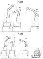
- FIG. 10 to FIG. 12 show embodiments of a system for control for prevention of interference between robots according to the present invention.
- a single robot control device 1 is used to control the drive operations of a plurality of robot mechanical parts R1 to Rn.
- the robot control device 1 is also provided with the functions of the robot interference control device according to the present invention.
- the robots R1 to Rn are provided with corresponding robot control devices 1-1 to 1-n, respectively.
- the robot control devices 1-1 to 1-n are connected by an Ethernet® or other network and transmit their internal variables through the network so as to enable the calculations for determining the scheduled stop positions and the judgment of the existence of interference to be performed in the robot control devices.
- the calculations for determining the scheduled stop positions and the judgment of the existence of occurrence of interference may also be performed all together at a single control device.
- FIG. 12 shows an embodiment designed for use with a personal computer or other outside computer 2.
- the computer 2 by connecting the computer 2 to a network of robot control devices 1-1 to 1-n and transmitting internal variables of the robot control devices 1-1 to 1-n to the computer 2, part or all of the calculations for determining the scheduled stop positions and the judgment of the existence of occurrence of interference can be performed at the computer 2.
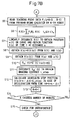
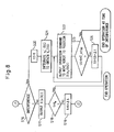
- FIGS. 7A and 7B and FIG. 8 are flow charts of the control processing for preventing interference between robots and show the processing at the embodiment shown in FIG. 10 .
- the robots (robot mechanical parts) for which an interference check is required is set in the robot control device 1, and data relating to the positions and shapes of the peripherals covered by the interference check is input and set in the robot control device 1. Further, the braking time T_stop is set in the robot control device 1.
- the processor of the robot control device 1 executes the interference check and interference prevention control processing shown in FIGS. 7A and 7B and FIG. 8 .
- the time t is set to "0" (step S1), the time t is set as the start time ta of the range for obtaining the B-spline curve from the string of teaching points, and "t+n ⁇ t+T_stop” is set as the end time tb of that range (step S2).
- n is an integer number of 1 or more and designates the number of interpolation periods for checking whether or not interference would occur after n number of interpolation periods from the current point of time. It is determined in advance. The "n” may be set before the start of operation.
- the counter K for counting the robots (robot mechanical parts) set for coverage by the check is set to "1" (step S4), and the teaching data P j between the knots t A to t B is read out from the programs being run by the robot indicated by the value of the counter K (step S5).
- the knots t A and t B as shown in equation (3), are integer values. The values correspond to the subscripts A and B of t A and t B , so the values of the knots are expressed by the subscripts A and B. Therefore, the teaching points P j read out from the program become P A-3 ,P A-2 ,... P B-1 .
- the obtained curve X(t) is linearly integrated by equation (5) to obtain the position s(t) on the curve.
- This position s(t) on the curve is the movement distance along the curve until the time t, so conversely if the distance s is given, the corresponding time t is uniquely determined. Therefore, the inverse function t(s) is obtained from the position function s(t) (step S7).
- the robot position and orientation are expressed by the function X(s), so the robot position and orientation at the time t are obtained as X(s(t)) (step S9) .
- the derived function of the function s(t) obtained at step S7 that is, the linear speed s'(t)
- the derived function s'(t) is multiplied by the function u(t-t0) to obtain the linear speed v t0 '(t) expressing the speed after deceleration based on the following equation (8) (step S10).
- v t ⁇ 0 ′ t s t ⁇ u ⁇ t ⁇ t ⁇ 0
- This linear speed V t0 '(t) is integrated from the deceleration start time t0 to the braking time T_stop to obtain the braking distance L_stop (step S11).
- step S15 when the scheduled stop position X (s(t+n ⁇ t)+L_stop) of the robot under check is determined, the interference between robots is checked and the interference with peripherals etc. is checked.
- This interference check as explained above, is performed by an already known method, so its explanation will be omitted.
- step S16 an operation command to move the robot to the interpolated position X(s(t)) at the time t obtained at step S9 for each robot is output to each robot (step S17). Further, it is judged whether or not the time t has reached the final time t N (step S18). If it has not reached it, the time t is incremented by exactly the unit interpolation period ⁇ t (step S19), then the procedure returns to step S2 where the processing of the above step S2 on is performed. After this, in so far as the occurrence of interference is not predicted, the above processing is repeated until the time t reaches the final time t N . When it reaches the final time t N , this interference prevention processing is ended.
- the current time t is set as the initial value for the tt showing the time at the time of deceleration (step S20), and the function v t ' (tt) expressing the speed obtained designating the deceleration start time as t and the time variable as tt from the function v t0 ' (t) expressing the speed at the time of the deceleration operation obtained at step S11 is integrated so as to obtain the amount of movement v t (tt) (step S21).
- step S23 it is judged whether or not the value of the time tt has reached the value of the deceleration start time t plus the braking time T_stop (step S23). If not reaching it, the time tt is incremented by the unit interpolation period ⁇ t (step S24). Then, the procedure returns to step S22, where the above processing is repeated until the value of the time tt reaches the value of the deceleration start time t plus the braking time T_stop and the robot stops.
- step S16 it is also possible to perform the signal output processing such as shown in FIG. 9 and output the results of judgment of the interference check to the peripherals etc.
- step S16 it is also possible to output a signal indicating that there would be interference to an outside device and jump to step S20 in the procedure.
- a single robot control device 1 of the system having the configuration shown in FIG. 10 is used to control a plurality of robots (robot mechanical parts) R1 to Rn and the interference prevention control device is formed by the robot control device 1.
- the processors of the robot control devices 11-1 to 1-n perform the processing shown in the above FIGS. 7A and 7B and FIG. 8 . Among them, the processing of step S4, S13, and S14 is not performed.
- the robot control devices collect the scheduled stop positions of the robots checked for interference through the network and use this robot control device for the interference check. When there would be interference, it is sufficient to stop the operation of the interfering robot or all of the robots in the system.
Landscapes
- Engineering & Computer Science (AREA)
- Robotics (AREA)
- Mechanical Engineering (AREA)
- Numerical Control (AREA)
- Manipulator (AREA)
- Safety Devices In Control Systems (AREA)
Claims (6)
- Roboterstörvermeidungs-Steuervorrichtung (10), die während eines Arbeitsvorgangs die Umgebung einer Vielzahl von Robotern erfasst, deren Arbeitsbereiche einander überlappen, und die die Roboter anhält, bevor sie einander behindern, wobei die Roboterstörverhinderungs-Steuervorrichtung gekennzeichnet ist durch:ein Haltepositionsberechnungsmittel (12) zum vorherigen Lesen eines durch jeden Roboter auszuführenden Anweisungsprogrammes und zum Berechnen einer geplanten Halteposition nach wenigstens einer vorbestimmten Interpolationsperiode von der Laufzeit jeder Interpolationsperiode für den Fall eines auszuführenden Haltebefehls für jeden Roboter;ein Störungserfassungsmittel (14) zum Erfassen einer vorliegenden Behinderung zwischen Robotern an jeder berechneten, geplanten Halteposition; undein Verzögerungsbefehlsmittel (16) zum Ausgeben des Befehls an den Roboter, eine Verzögerung zu beginnen, wenn das Störungserfassungsmittel feststellt, dass eine Behinderung vorliegt.
- Roboterstörvermeidungs-Steuervorrichtung gemäß Anspruch 1, wobei das Haltepositionsberechnungsmittel (12) im Voraus das durch jeden Roboter auszuführende Anweisungsprogramm liest, die Position und Orientierung jedes Roboters als eine Funktion der Zeit t ausdrückt und diese Funktion nutzt, um eine geplante Halteposition für den Fall zu berechnen, dass ein Haltebefehl für jeden Roboter nach wenigstens einer vorbestimmten Interpolationsperiode von der Laufzeit jeder Interpolationsperiode ausgeführt wird.
- Roboterstörvermeidungs-Steuervorrichtung gemäß Anspruch 2, wobei das Haltepositionsberechnungsmittel (12) eine geplante Halteposition von dem Wert der Funktion zur Zeit t+n*Δt+T_stop berechnet, wobei t die Zeit zu einem bestimmten Zeitpunkt, t+n*Δt die Zeit nach wenigstens einer Interpolationsperiode von der Laufzeit ausdrückt und T_stop die zum Anhalten benötigte Zeit angibt.
- Roboterstörverhinderungs-Steuervorrichtung gemäß Anspruch 2 oder 3, wobei die Position und Orientierung des Roboters durch eine lineare Summe der Funktion der Zeit t ausgedrückt wird.
- Roboterstörvermeidungs-Steuervorrichtung gemäß Anspruch 1 oder 2, mit einem Mittel (18) zum Ausgeben der Ergebnisse der Bewertung des Störerfassungsmittel (14) an die Umgebung in Form eines Signals.
- Roboterstörvermeidungs-Steuervorrichtung gemäß Anspruch 1 oder 2, wobei Form und Positionsdaten des Umfelds, in dem Behinderungen auftreten, im Voraus festgelegt werden, und das Störungserfassungsmittel (14) ferner Behinderungen zwischen den Robotern und dem Umfeld erfasst.
Applications Claiming Priority (1)
| Application Number | Priority Date | Filing Date | Title |
|---|---|---|---|
| JP2004255881A JP3907649B2 (ja) | 2004-09-02 | 2004-09-02 | ロボット間の干渉防止制御装置 |
Publications (3)
| Publication Number | Publication Date |
|---|---|
| EP1632318A2 EP1632318A2 (de) | 2006-03-08 |
| EP1632318A3 EP1632318A3 (de) | 2009-08-12 |
| EP1632318B1 true EP1632318B1 (de) | 2011-01-19 |
Family
ID=35431169
Family Applications (1)
| Application Number | Title | Priority Date | Filing Date |
|---|---|---|---|
| EP05018886A Ceased EP1632318B1 (de) | 2004-09-02 | 2005-08-31 | Steuerungsgerät zur Robotersinterferenzvermeidung |
Country Status (5)
| Country | Link |
|---|---|
| US (1) | US20060052901A1 (de) |
| EP (1) | EP1632318B1 (de) |
| JP (1) | JP3907649B2 (de) |
| CN (1) | CN100355540C (de) |
| DE (1) | DE602005025967D1 (de) |
Families Citing this family (44)
| Publication number | Priority date | Publication date | Assignee | Title |
|---|---|---|---|---|
| JP2008009588A (ja) * | 2006-06-28 | 2008-01-17 | Ihi Corp | シミュレーション装置、方法およびプログラム |
| JP4221016B2 (ja) | 2006-07-25 | 2009-02-12 | ファナック株式会社 | 干渉チェックを行う数値制御装置 |
| KR100863989B1 (ko) | 2007-04-24 | 2008-10-16 | 대우조선해양 주식회사 | 선체 소조립 용접로봇의 대기시간 최소화 및 충돌방지방법 |
| JP4298770B2 (ja) * | 2007-08-28 | 2009-07-22 | ファナック株式会社 | 干渉チェック機能を備えた数値制御装置 |
| JP5365524B2 (ja) * | 2007-12-07 | 2013-12-11 | 株式会社安川電機 | ロボット動作規制方法およびロボットシステム |
| JP4951783B2 (ja) * | 2008-02-01 | 2012-06-13 | 株式会社デンソーウェーブ | ロボット制御装置及びロボット制御方法 |
| JP5025598B2 (ja) * | 2008-08-29 | 2012-09-12 | 三菱電機株式会社 | 干渉チェック制御装置および干渉チェック制御方法 |
| JP5036661B2 (ja) * | 2008-08-29 | 2012-09-26 | 三菱電機株式会社 | 干渉チェック制御装置および干渉チェック制御方法 |
| DE102009023307A1 (de) * | 2009-05-29 | 2010-12-02 | Kuka Roboter Gmbh | Verfahren und Vorrichtung zur Steuerung eines Manipulators |
| JP5218524B2 (ja) * | 2010-03-15 | 2013-06-26 | 株式会社安川電機 | ロボットシステムおよびロボット動作規制方法 |
| DE102010063208A1 (de) * | 2010-12-16 | 2012-06-21 | Robert Bosch Gmbh | Verfahren zum Betreiben einer Sicherungseinrichtung für eine Handhabungsvorrichtung, Sicherungseinrichtung für eine Handhabungsvorrichtung und Handhabungsvorrichtung |
| JP2012216151A (ja) * | 2011-04-01 | 2012-11-08 | Mitsubishi Electric Corp | 干渉回避制御装置 |
| ITTO20110994A1 (it) * | 2011-10-31 | 2013-05-01 | Comau Spa | Metodo per il controllo di almeno due robot aventi rispettivi spazi di lavoro includenti almeno una regione in comune |
| JP5872894B2 (ja) * | 2011-12-28 | 2016-03-01 | 川崎重工業株式会社 | ロボット動作教示支援装置及び方法 |
| DE102014118001A1 (de) * | 2014-12-05 | 2016-06-09 | Broetje-Automation Gmbh | Verfahren zur Bewegungssimulation eines Manipulators |
| CN106181963A (zh) * | 2014-12-19 | 2016-12-07 | 库卡罗伯特有限公司 | 机器人系统 |
| DE102014226789A1 (de) | 2014-12-22 | 2016-07-07 | Kuka Roboter Gmbh | Verfahren und Manipulatoranordnung zum bedingten Anhalten zumindest eines Manipulators auf einer Bahn |
| US20160180860A1 (en) * | 2014-12-23 | 2016-06-23 | Qualcomm Incorporated | High order B-spline sampling rate conversion (SRC) |
| CN106182040B (zh) * | 2014-12-23 | 2021-10-15 | 库卡罗伯特有限公司 | 机器人系统 |
| JP6200456B2 (ja) * | 2015-06-29 | 2017-09-20 | ファナック株式会社 | 工作機械とロボット間の干渉チェックシステム |
| JP6411964B2 (ja) * | 2015-07-27 | 2018-10-24 | ファナック株式会社 | 工作機械とロボットのリアルタイム干渉確認システム |
| DE102015113110B4 (de) | 2015-08-10 | 2019-03-14 | MAQUET GmbH | Ansteuervorrichtung mindestens einer Antriebseinrichtung eines Operationstisches und Verfahren zum Ansteuern |
| JP6654926B2 (ja) * | 2016-02-24 | 2020-02-26 | 本田技研工業株式会社 | 処理時間の予測方法 |
| DE102016005026B3 (de) * | 2016-04-24 | 2017-05-18 | Sami Haddadin | System und Verfahren zum Steuern eines Roboters |
| JP6801333B2 (ja) * | 2016-09-27 | 2020-12-16 | 株式会社デンソーウェーブ | ロボット用の表示システム |
| JP6603255B2 (ja) | 2017-03-13 | 2019-11-06 | ファナック株式会社 | ロボットシステムおよびロボット制御方法 |
| DE102017005137B4 (de) * | 2017-05-30 | 2020-09-24 | Infineon Technologies Austria Ag | Stromleitungsgesteuerte elektrische Antriebsinverter |
| JP7013766B2 (ja) * | 2017-09-22 | 2022-02-01 | セイコーエプソン株式会社 | ロボット制御装置、ロボットシステム、及び制御方法 |
| DE102017123295A1 (de) * | 2017-10-06 | 2019-04-11 | Pilz Gmbh & Co. Kg | Sicherheitssystem zur Absicherung eines kooperativen Betriebs von Menschen, Robotern und Maschinen |
| CN108044624A (zh) * | 2017-12-11 | 2018-05-18 | 上海信耀电子有限公司 | 一种基于powerlink总线的机器人控制系统 |
| EP3498433A1 (de) | 2017-12-14 | 2019-06-19 | Universal Robots A/S | Dynamische sicherheitstrajektorien in einem robotersystem |
| WO2019238975A1 (en) | 2018-06-15 | 2019-12-19 | Universal Robots A/S | Dual mode free-drive of robot arm |
| DE102018133472B3 (de) * | 2018-12-21 | 2020-03-12 | Franka Emika Gmbh | Bewegungsüberwachung eines Robotermanipulators |
| CN110216675B (zh) * | 2019-06-20 | 2021-04-06 | 北京猎户星空科技有限公司 | 智能机器人的控制方法、装置、智能机器人及计算机设备 |
| EP4049104B1 (de) | 2019-10-22 | 2026-02-18 | Universal Robots A/S | Roboterarm mit adaptiver dreidimensionaler begrenzung im freilauf |
| WO2021078344A1 (en) | 2019-10-22 | 2021-04-29 | Universal Robots A/S | Safe activation of free-drive mode of robot arm |
| DK180508B1 (en) | 2019-10-22 | 2021-06-03 | Universal Robots As | Maintaining free-drive mode of robot arm for period of time |
| CN111015669B (zh) * | 2019-12-27 | 2022-03-11 | 南京埃斯顿机器人工程有限公司 | 一种工业机器人停止运动轨迹规划方法 |
| JP7484254B2 (ja) * | 2020-03-13 | 2024-05-16 | オムロン株式会社 | 干渉判定装置、方法、及びプログラム |
| DE112021001607B4 (de) * | 2020-05-25 | 2026-01-22 | Fanuc Corporation | Offlinelehrvorrichtung und bewegungsprogrammerzeugungsverfahren |
| TW202233369A (zh) * | 2021-02-18 | 2022-09-01 | 日商發那科股份有限公司 | 機器人控制裝置、機器人控制系統、及電腦程式 |
| CN113334392B (zh) * | 2021-08-06 | 2021-11-09 | 成都博恩思医学机器人有限公司 | 一种机械臂防碰撞方法、装置、机器人及存储介质 |
| CN116149340B (zh) * | 2023-04-23 | 2023-06-30 | 季华实验室 | 差速轮底盘机器人自适应路径跟随方法及其相关设备 |
| CN121338955B (zh) * | 2025-12-17 | 2026-03-17 | 国营洛阳丹城无线电厂 | 一种基于机器视觉引导的精密喷涂定位系统及方法 |
Family Cites Families (20)
| Publication number | Priority date | Publication date | Assignee | Title |
|---|---|---|---|---|
| JPS6099591A (ja) * | 1983-11-02 | 1985-06-03 | 株式会社日立製作所 | 協調作業におけるロボツト腕の干渉チエツク方式 |
| US4998206A (en) * | 1988-07-29 | 1991-03-05 | The Boeing Company | Automated method and apparatus for fabricating sheet metal parts and the like using multiple manufacturing stations |
| US4644237A (en) * | 1985-10-17 | 1987-02-17 | International Business Machines Corp. | Collision avoidance system |
| US5304906A (en) * | 1989-12-26 | 1994-04-19 | Fanuc Ltd. | Collision detecting method using an observer |
| FR2682905B1 (fr) * | 1991-10-28 | 1995-12-01 | Commissariat Energie Atomique | Procede de generation de trajectoire pour un systeme robotise. |
| JP2895672B2 (ja) * | 1992-01-28 | 1999-05-24 | ファナック株式会社 | 複数ロボット制御方法 |
| KR100257916B1 (ko) * | 1995-06-13 | 2002-04-17 | 다나베 히로까즈 | 산업용 로봇에 있어서의 간섭회피방법 |
| US5732194A (en) * | 1995-08-04 | 1998-03-24 | Ford Global Technologies, Inc. | Computer controlled reconfigurable part fixture mechanism |
| JPH103308A (ja) * | 1996-06-18 | 1998-01-06 | Fanuc Ltd | 産業用ロボットの干渉回避方法 |
| US6325749B1 (en) * | 1996-10-18 | 2001-12-04 | Kabushiki Kaisha Yaskawa Denki | Robot vehicle for hot-line job |
| JP2000190262A (ja) * | 1998-12-22 | 2000-07-11 | Denso Corp | ロボットの制御装置 |
| JP3842493B2 (ja) * | 1999-10-04 | 2006-11-08 | 富士通株式会社 | 3次元オブジェクト共有処理方法及び記憶媒体 |
| US6558803B1 (en) * | 2000-07-03 | 2003-05-06 | Adhesives Research Inc. | Ambifunctional perfluorinated polyethers |
| US7390458B2 (en) * | 2000-10-13 | 2008-06-24 | Irm Llc | High throughput processing system and method of using |
| US7114157B2 (en) * | 2001-11-27 | 2006-09-26 | Kuka Roboter Gmbh | System controlling exclusive access by control programs to system resources |
| US6817829B2 (en) * | 2001-12-25 | 2004-11-16 | Komatsu Ltd. | Work loading method for automatic palletizer, work loading method, work loading apparatus and attachment replacing method thereof |
| JP4295947B2 (ja) * | 2002-02-15 | 2009-07-15 | ソニー株式会社 | 脚式移動ロボット及びその移動制御方法 |
| US6678582B2 (en) * | 2002-05-30 | 2004-01-13 | Kuka Roboter Gmbh | Method and control device for avoiding collisions between cooperating robots |
| JP3975959B2 (ja) * | 2003-04-23 | 2007-09-12 | トヨタ自動車株式会社 | ロボット動作規制方法とその装置およびそれを備えたロボット |
| DE10361132B4 (de) * | 2003-06-18 | 2013-02-28 | Elan Schaltelemente Gmbh & Co. Kg | Verfahren zur Überwachung der Bewegung eines sich in mehreren Freiheitsgraden bewegenden Gefahr bringenden Objektes eines Handhabungsgerätes, wie Handhabungsmasse und/oder bewegliche Masse |
-
2004
- 2004-09-02 JP JP2004255881A patent/JP3907649B2/ja not_active Expired - Fee Related
-
2005
- 2005-08-31 EP EP05018886A patent/EP1632318B1/de not_active Ceased
- 2005-08-31 DE DE602005025967T patent/DE602005025967D1/de not_active Expired - Lifetime
- 2005-09-01 CN CNB2005100982453A patent/CN100355540C/zh not_active Expired - Fee Related
- 2005-09-02 US US11/217,413 patent/US20060052901A1/en not_active Abandoned
Also Published As
| Publication number | Publication date |
|---|---|
| EP1632318A2 (de) | 2006-03-08 |
| DE602005025967D1 (de) | 2011-03-03 |
| US20060052901A1 (en) | 2006-03-09 |
| JP3907649B2 (ja) | 2007-04-18 |
| CN1743148A (zh) | 2006-03-08 |
| CN100355540C (zh) | 2007-12-19 |
| EP1632318A3 (de) | 2009-08-12 |
| JP2006068857A (ja) | 2006-03-16 |
Similar Documents
| Publication | Publication Date | Title |
|---|---|---|
| EP1632318B1 (de) | Steuerungsgerät zur Robotersinterferenzvermeidung | |
| US8126585B2 (en) | Collision preventing device incorporated in numerical control apparatus | |
| Park et al. | ITOMP: Incremental trajectory optimization for real-time replanning in dynamic environments | |
| EP1901150B1 (de) | Verfahren und Vorrichtung zur Vermeidung von Kollisionen zwischen einem Industrieroboter und einem Objekt | |
| JP7262847B2 (ja) | 安全重視用途に関する産業ロボット動力学のシステム識別 | |
| EP2107392A1 (de) | Gegenstanderkennungssystem für autonomen beweglichen Körper | |
| EP2090407A1 (de) | Robotersteuergerät mit Komponentenschutzfunktion und Robotersteuerverfahren | |
| CN113710432A (zh) | 用于确定机器人的轨迹的方法 | |
| KR102003206B1 (ko) | 주변 환경과의 접촉을 고려한 로봇 액추에이터의 제어 및 조정 | |
| EP1517205A3 (de) | Steuerung für Machine | |
| JP2020097091A (ja) | ロボット干渉判定装置、ロボット干渉判定方法、ロボット制御装置、ロボット制御システム、人動作予測装置、および人動作予測方法 | |
| JP2010052116A (ja) | 干渉チェック制御装置および干渉チェック制御方法 | |
| JP2026009312A (ja) | ロボット制御装置、ロボット制御システム、及びロボット制御方法 | |
| JP2006215807A (ja) | ロボット制御装置および制御方法 | |
| CN119604824A (zh) | 用于多机器人环境的鲁棒运动规划和/或控制 | |
| CN120080323B (zh) | Cnc机床上下料机器人多模态运动控制系统及方法 | |
| EP4052864B1 (de) | Verfahren zur automatischen einstellung der kollisionsempfindlichkeit eines kollaborativen roboters | |
| JP2003076410A (ja) | 速度制御装置、速度制御方法およびその方法をコンピュータに実行させるプログラム | |
| JP2007257094A (ja) | 経路作成方法、移動体および移動体制御システム | |
| JP3975341B2 (ja) | ロボットの干渉チェック方法 | |
| JPH07210233A (ja) | ロボットの軌道の補間方法と補間装置 | |
| US12017372B2 (en) | Robot control device | |
| JPH09251320A (ja) | ロボット衝突防止システム | |
| JP3586874B2 (ja) | 加減速制御方法 | |
| US20240269836A1 (en) | Automatic machine control device and automatic machine control method |
Legal Events
| Date | Code | Title | Description |
|---|---|---|---|
| PUAI | Public reference made under article 153(3) epc to a published international application that has entered the european phase |
Free format text: ORIGINAL CODE: 0009012 |
|
| AK | Designated contracting states |
Kind code of ref document: A2 Designated state(s): AT BE BG CH CY CZ DE DK EE ES FI FR GB GR HU IE IS IT LI LT LU LV MC NL PL PT RO SE SI SK TR |
|
| AX | Request for extension of the european patent |
Extension state: AL BA HR MK YU |
|
| PUAL | Search report despatched |
Free format text: ORIGINAL CODE: 0009013 |
|
| AK | Designated contracting states |
Kind code of ref document: A3 Designated state(s): AT BE BG CH CY CZ DE DK EE ES FI FR GB GR HU IE IS IT LI LT LU LV MC NL PL PT RO SE SI SK TR |
|
| AX | Request for extension of the european patent |
Extension state: AL BA HR MK YU |
|
| 17P | Request for examination filed |
Effective date: 20100118 |
|
| AKX | Designation fees paid |
Designated state(s): DE |
|
| RIC1 | Information provided on ipc code assigned before grant |
Ipc: B25J 9/16 20060101AFI20100603BHEP |
|
| GRAC | Information related to communication of intention to grant a patent modified |
Free format text: ORIGINAL CODE: EPIDOSCIGR1 |
|
| GRAP | Despatch of communication of intention to grant a patent |
Free format text: ORIGINAL CODE: EPIDOSNIGR1 |
|
| GRAS | Grant fee paid |
Free format text: ORIGINAL CODE: EPIDOSNIGR3 |
|
| GRAA | (expected) grant |
Free format text: ORIGINAL CODE: 0009210 |
|
| AK | Designated contracting states |
Kind code of ref document: B1 Designated state(s): DE |
|
| RAP2 | Party data changed (patent owner data changed or rights of a patent transferred) |
Owner name: FANUC CORPORATION |
|
| REF | Corresponds to: |
Ref document number: 602005025967 Country of ref document: DE Date of ref document: 20110303 Kind code of ref document: P |
|
| REG | Reference to a national code |
Ref country code: DE Ref legal event code: R096 Ref document number: 602005025967 Country of ref document: DE Effective date: 20110303 |
|
| PLBE | No opposition filed within time limit |
Free format text: ORIGINAL CODE: 0009261 |
|
| STAA | Information on the status of an ep patent application or granted ep patent |
Free format text: STATUS: NO OPPOSITION FILED WITHIN TIME LIMIT |
|
| 26N | No opposition filed |
Effective date: 20111020 |
|
| REG | Reference to a national code |
Ref country code: DE Ref legal event code: R097 Ref document number: 602005025967 Country of ref document: DE Effective date: 20111020 |
|
| PGFP | Annual fee paid to national office [announced via postgrant information from national office to epo] |
Ref country code: DE Payment date: 20220621 Year of fee payment: 18 |
|
| REG | Reference to a national code |
Ref country code: DE Ref legal event code: R119 Ref document number: 602005025967 Country of ref document: DE |
|
| PG25 | Lapsed in a contracting state [announced via postgrant information from national office to epo] |
Ref country code: DE Free format text: LAPSE BECAUSE OF NON-PAYMENT OF DUE FEES Effective date: 20240301 |