EP1632312A2 - Dispositif de mise sous tension de vis ou boulons avec pièce pour absorber des forces de réaction - Google Patents
Dispositif de mise sous tension de vis ou boulons avec pièce pour absorber des forces de réaction Download PDFInfo
- Publication number
- EP1632312A2 EP1632312A2 EP05013262A EP05013262A EP1632312A2 EP 1632312 A2 EP1632312 A2 EP 1632312A2 EP 05013262 A EP05013262 A EP 05013262A EP 05013262 A EP05013262 A EP 05013262A EP 1632312 A2 EP1632312 A2 EP 1632312A2
- Authority
- EP
- European Patent Office
- Prior art keywords
- motor
- tightening
- nut
- bolt
- reaction force
- Prior art date
- Legal status (The legal status is an assumption and is not a legal conclusion. Google has not performed a legal analysis and makes no representation as to the accuracy of the status listed.)
- Withdrawn
Links
Images


Classifications
-
- B—PERFORMING OPERATIONS; TRANSPORTING
- B25—HAND TOOLS; PORTABLE POWER-DRIVEN TOOLS; MANIPULATORS
- B25B—TOOLS OR BENCH DEVICES NOT OTHERWISE PROVIDED FOR, FOR FASTENING, CONNECTING, DISENGAGING OR HOLDING
- B25B23/00—Details of, or accessories for, spanners, wrenches, screwdrivers
- B25B23/0078—Reaction arms
-
- B—PERFORMING OPERATIONS; TRANSPORTING
- B25—HAND TOOLS; PORTABLE POWER-DRIVEN TOOLS; MANIPULATORS
- B25B—TOOLS OR BENCH DEVICES NOT OTHERWISE PROVIDED FOR, FOR FASTENING, CONNECTING, DISENGAGING OR HOLDING
- B25B21/00—Portable power-driven screw or nut setting or loosening tools; Attachments for drilling apparatus serving the same purpose
-
- B—PERFORMING OPERATIONS; TRANSPORTING
- B25—HAND TOOLS; PORTABLE POWER-DRIVEN TOOLS; MANIPULATORS
- B25B—TOOLS OR BENCH DEVICES NOT OTHERWISE PROVIDED FOR, FOR FASTENING, CONNECTING, DISENGAGING OR HOLDING
- B25B23/00—Details of, or accessories for, spanners, wrenches, screwdrivers
- B25B23/14—Arrangement of torque limiters or torque indicators in wrenches or screwdrivers
- B25B23/147—Arrangement of torque limiters or torque indicators in wrenches or screwdrivers specially adapted for electrically operated wrenches or screwdrivers
Definitions
- the present invention relates to bolt or nut tightening devices having a reaction force receiving member.
- the present applicant has provided several kinds of bolt or nut tightening devices comprising a tightening socket and a reaction force receiving member, the socket being rotatingly drivable by a motor and reduction means which are incorporated in the device (see, for example, JP-A No. 7-88777 and JP-A No. 8-197345).
- the reaction force receiving member is brought into contact with a nut or like projection positioned in the vicinity of the nut to be tightened up for the projection to receive the reaction force of tightening.
- Conventional tightening devices having a reaction force receiving member are used for bolts and nuts having a large nominal diameter, and the devices are large-sized.
- Bolt and nuts having a small nominal diameter can be tightened up at a high speed by impact wrenches, which are therefore efficient to use.
- impact wrenches have the problem of releasing a loud noise during operation and impairing the work environment.
- the receiving member When a nut is completely tightened up by the tightening device having a reaction force receiving member, the receiving member, as positioned between the tightened-up nut and a projection receiving the reaction force, performs a propping action with a great force in the direction of rotation of the tightening socket, and the device including the reaction force receiving member elastically deforms although slightly, regardless of whether the device is large-sized or small. Further even if the motor is deenergized after the completion of tightening, the motor rotates through inertia, exerting a force to hold the device elastically deformed.
- the large tightening device has high rigidity in its entirety including the reaction force receiving member and therefore elastically restores itself effectively. Accordingly, if the motor is deenergized after the completion of tightening, the tightening device including the reaction force receiving member elastically restores itself, and the propping action of the receiving member as positioned between the tightened-up nut and the projection will be nullified automatically. Consequently, the tightening socket is smoothly removable from the nut.
- the device can not be removed from the bolt and nut even if pulled straight axially of the bolt and nut.
- the tightening device must be forcibly removed, as inclined with respect to the axis of the bolt and nut, from the bolt and nut.
- a forward-reverse changeover switch is manipulated for the motor, and the operation switch (trigger) is then pulled to reversely rotate the motor for a short period of time to nullify the propping action of the reaction force receiving member.
- the former case requires labor and is inefficient.
- An object of the present invention is to a small-sized tightening device which has a tightening socket and a reaction force receiving member, the socket being readily removable from the bolt or nut as completely tightened up although the device is compacted.
- the present invention provides a device for tightening a bolt or a nut and comprising a tightening socket and a reaction force receiving member, the tightening socket being rotatingly drivable upon a speed reduction by a motor and a reduction mechanism which are incorporated in the device, the motor being coupled to a controller, the controller being operable to deenergize the motor in response to a tightening completion signal of detecting means for detecting the completion of tightening of a bolt or nut and to reversely rotate the motor only for a moment upon lapse of a predetermined period of time taken for inertial rotation of the motor to reduce to an extent neglectable for the reverse rotation of the motor after the deenergization.
- the motor When the bolt or nut is completely tightened up, the motor is automatically rotated reversely, so that the reaction force receiving member is released from a propping action, and the tightening socket can be removed from the bolt or nut easily.
- the motor is reversely rotated with a slight time delay after the deenergization of the motor, that is, the motor is reversely rotated after the motor in inertial rotation is slowed down or after the motor is brought out of inertial rotation. This lessens the load on the motor and on the controller, preventing these components from damage.
- the bolt or nut is tightened and the motor is reversely rotated for a moment, with the operation switch (trigger) pulled, so that there is no need for a cumbersome manual procedure for changing over a switch, with the result that many bolts and nuts can be tightened up with a very high efficiency.
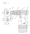
- FIG. 1 shows a bolt or nut tightening device which comprises a motor 2 provided in a rear portion of a casing 1, a planetary gear reduction mechanism 3 housed in a front tubular portion 12 of the casing and operable by the motor 2, and a handle 11 extending downward from the casing rear portion.
- a rechargeable battery 8 is removably installed in the lower end of the handle 11.
- An output shaft 31 and a reaction force receiving shaft 32 are coaxially coupled to the planetary gear reduction mechanism 3 so as to be rotatable in opposite directions to each other.
- the two shafts 31, 32 project forward from the forward end of the casing front tubular portion 12.
- the output shaft 31 has removably connected thereto a tightening socket 4 engageable with the head of a bolt or a nut (hereinafter referred to typically as a "nut N”) .
- the socket 4 of the embodiment is adapted for use with hexagonal nuts.
- the reaction force receiving shaft 32 is provided with a reaction force receiving member 5 projecting in a direction orthogonal to the axis of the shaft 32.
- the motor 2 of the embodiment is a brushless DC motor.
- the brushless DC motor 2 has a drive circuit 21.
- the handle 11 is provided with an operation switch (trigger) 6, rotation direction change switch 61 and controller 7.
- the rotation direction change switch 61 is used for changing the direction of rotation of the motor 2 when the nut N is loosened or when tightening up a nut which is reversely threaded.
- the controller 7 When detecting means 70 detects the tightening of the nut N by the rotation of the tightening socket 4, the controller 7 operates to momentarily reverse the rotation of the motor 2 (reversely rotate the motor for a moment) with a slight delay after the detection of completion of the tightening, with the operation switch 6 in the pulled state (for energization) .
- the detecting means 70 of the embodiment produces a detection signal upon the value of current to the motor 2 reaching a specified level. It is well known that the value of torque for tightening the nut N is substantially in proportion to the value of current to the motor 2, and it is conventional practice to detect the nut tightening torque from the current value.
- the handle 11 of the tightening device is provided with a torque setting dial 70a, by which the device can be set to an optimum tightening torque corresponding to the nominal diameter of the nut to be tightened up.
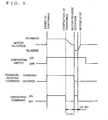
- the controller 7 comprises a tightening sequence circuit 71, and an operation command circuit 72 and a rotation direction command circuit 73 each adapted to feed a signal to the drive circuit of the brushless DC motor 2 in response to a command from the sequence circuit 71.
- the tightening sequence circuit 71 has a digital timer (not shown) and is capable of delaying the transmission of a signal to the operation command circuit 72 by a set period of time and setting the duration of reverse rotation of the motor 2.
- the time delay in transmitting the signal is a period of time required for the motor 2 in inertial rotation to slow down to such a speed that will not be objectionable to reverse the rotation of the motor 2 after the deenergization of the motor 2. It is desired that the time delay be within one second which is a period of time to be elapsed after the completion of tightening until the reverse rotation of the motor 2 without causing the worker to feel the delay as too great a retardation.
- the time delay of the embodiment is 0.5 second.
- the duration of reverse rotation of the motor 2 (stated precisely, the duration of energization of the motor 2 toward the direction of reverse rotation) is 0.01 second according to the embodiment; the motor 2 needs only to be reversely rotated for such a short period of time that will relieve the tightening device of the elastic deformation involved in the completion of tightening and that will not permit the nut N as tightened up to loosen.
- the operation switch 6 and the rotation direction change switch 61 are coupled to the tightening sequence circuit 71.
- the detecting means 70 feeds a signal to the tightening sequence circuit 71 to deenergize the motor 2.
- the reaction force receiving member 5 of the tightening device is in bearing contact with the projection M, preventing the device from rotating in a direction opposite to the tightening direction.
- a motor reverse rotation command and an operation command are sent to the motor 2, 0.5 second after the deenergization of the motor 2, the motor 2 reversely rotates for a moment, and the motor 2 is deenergized again.
- the reverse rotation of the motor 2 releases the tightening device 5 including the reaction force receiving member 5 from the elastic deformation due to the propping action of the member 5, nullifying the propping action of the reaction force receiving member 5.
- the tightening socket 4 can be removed from the nut N without any resistance by pulling the tightening device axially of the nut N.
- the operation switch 6 remains pulled after the start of the nut tightening operation until the motor 2 is brought out of rotation, hence no need for cumbersome switch manipulation.
- the brushless DC motor 2 has the drive circuit 21 incorporated therein, necessitates no additional switch circuit comprising a relay circuit or transistor circuit for reverse rotation control and therefore serves to make the controller 7 compact. For this reason, the present invention can be embodied favorably into a hand-held tightening device provided with a battery.
- the brushless DC motor 21 is easy to control, the rotational speed of the motor for tightening and the reverse rotation speed thereof can be altered as required.
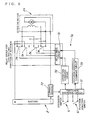
- FIG. 6 shows an embodiment of controller 7a comprising a series DC motor 2a which is increased in power even at a low speed.
- the controller 7a comprises four electromagnetic relays 74 for changing the flow of current through the motor 2a to a reverse direction and a relay drive circuit 75 for controlling the relays, in addition to the components already described, i.e., the tightening completion detecting means 70, tightening sequence circuit 71, operation command circuit 72 and rotation direction command circuit 73.
- the four relays 74 are bulky to make the entire controller large-sized, so that the controller is not suitable for hand-held tightening devices.
- FIG. 7 shows an embodiment wherein four semiconductor switches (transistors) 76 are used for rotating a series DC motor 2a forward and reversely.
- a controller 7b comprises four semiconductor switches 76 for changing the flow of current through the motor 2a to a reverse direction, a gate drive circuit 77 for controlling these switches and a radiator 78, in addition to the components already described, i.e., the tightening completion detecting means 70, tightening sequence circuit 71, operation command circuit 72 and rotation direction command circuit 73.
- the radiator 78 is bulky to make the controller 7b large-sized, so that the controller is not suitable for hand-held tightening devices.
- the tightening socket 4 of the embodiment is adapted for use with hexagonal nuts, the socket is not so limited.
- the socket 4 has a cavity or a polygonal rod engageable with the bolt or nut to be tightened, for example, if the socket 4 has a projecting hexagonal rod engageable in a hexagon-shaped socket head of a bolt, the socket corresponds to the socket of the tightening device of the invention.
Landscapes
- Engineering & Computer Science (AREA)
- Mechanical Engineering (AREA)
- Details Of Spanners, Wrenches, And Screw Drivers And Accessories (AREA)
Applications Claiming Priority (1)
| Application Number | Priority Date | Filing Date | Title |
|---|---|---|---|
| JP2004181994A JP2006000993A (ja) | 2004-06-21 | 2004-06-21 | 反力受け付き締付機 |
Publications (2)
| Publication Number | Publication Date |
|---|---|
| EP1632312A2 true EP1632312A2 (fr) | 2006-03-08 |
| EP1632312A3 EP1632312A3 (fr) | 2009-04-22 |
Family
ID=34979149
Family Applications (1)
| Application Number | Title | Priority Date | Filing Date |
|---|---|---|---|
| EP05013262A Withdrawn EP1632312A3 (fr) | 2004-06-21 | 2005-06-20 | Dispositif de mise sous tension de vis ou boulons avec pièce pour absorber des forces de réaction |
Country Status (3)
| Country | Link |
|---|---|
| US (1) | US7011000B2 (fr) |
| EP (1) | EP1632312A3 (fr) |
| JP (1) | JP2006000993A (fr) |
Cited By (5)
| Publication number | Priority date | Publication date | Assignee | Title |
|---|---|---|---|---|
| EP2199032A3 (fr) * | 2008-12-16 | 2011-06-22 | Techtronic Power Tools Technology Limited | Transmission automatique d'outil électrique |
| CN103507017A (zh) * | 2012-06-26 | 2014-01-15 | 广西玉柴机器股份有限公司 | 拧紧扳手反力矩机构 |
| TWI451944B (zh) * | 2009-08-14 | 2014-09-11 | Tai Her Yang | 遊星齒輪驅動式倍力驅動工具 |
| CN105500261A (zh) * | 2014-09-26 | 2016-04-20 | 苏州宝时得电动工具有限公司 | 动力工具及其操作方法 |
| FR3154028A1 (fr) * | 2023-10-17 | 2025-04-18 | Etablissements Georges Renault | Dispositif de vissage/dévissage à détorsion optimisée |
Families Citing this family (38)
| Publication number | Priority date | Publication date | Assignee | Title |
|---|---|---|---|---|
| US7225707B2 (en) * | 2005-09-14 | 2007-06-05 | Brian Knopp | Torque wrench with quick-release gear set |
| JP4974643B2 (ja) * | 2006-10-30 | 2012-07-11 | 前田金属工業株式会社 | ボルト・ナット締付装置 |
| US7735398B2 (en) * | 2007-02-13 | 2010-06-15 | Techway Industrial Co., Ltd. | Rechargeable motor-driven ratchet wrench having power-off protection |
| DE102007019408B3 (de) * | 2007-04-23 | 2008-11-27 | Lösomat Schraubtechnik Neef Gmbh | Kraftschrauber |
| DE102007019409B3 (de) * | 2007-04-23 | 2008-11-13 | Lösomat Schraubtechnik Neef Gmbh | Kraftschrauber |
| SE531646C2 (sv) * | 2007-10-17 | 2009-06-16 | Atlas Copco Tools Ab | Skruvdragare med organ för övervakning av en reaktionsarm |
| US11999516B2 (en) | 2008-04-23 | 2024-06-04 | Signode Industrial Group Llc | Strapping device |
| EP2271553B1 (fr) * | 2008-04-23 | 2013-04-10 | Orgapack GmbH | Dispositif de banderolage mobile |
| CN201411057Y (zh) * | 2008-04-23 | 2010-02-24 | 奥格派克有限公司 | 带有电子传动装置的捆扎设备 |
| US10518914B2 (en) | 2008-04-23 | 2019-12-31 | Signode Industrial Group Llc | Strapping device |
| CN201411059Y (zh) * | 2008-04-23 | 2010-02-24 | 奥格派克有限公司 | 带有储能器的捆扎设备 |
| EP2285691B1 (fr) | 2008-04-23 | 2015-03-11 | Premark Packaging LLC | Dispositif de banderolage comportant un dispositif tendeur |
| RU2462403C2 (ru) * | 2008-04-23 | 2012-09-27 | Оргапак Гмбх | Обвязочное устройство с передаточным механизмом |
| JP5561535B2 (ja) * | 2010-05-31 | 2014-07-30 | 日立工機株式会社 | 電動工具 |
| JP5559718B2 (ja) * | 2011-02-07 | 2014-07-23 | パナソニック株式会社 | 電動工具 |
| CH705743A2 (de) | 2011-11-14 | 2013-05-15 | Illinois Tool Works | Umreifungsvorrichtung. |
| US9108307B2 (en) | 2012-08-31 | 2015-08-18 | Honda Motor Co., Ltd. | Apparatus including powered tool configured to fasten fastener to assembly |
| US9938029B2 (en) | 2012-09-24 | 2018-04-10 | Signode Industrial Group Llc | Strapping device having a pivotable rocker |
| CN103846849A (zh) * | 2012-11-30 | 2014-06-11 | 奇力速工业股份有限公司 | 可侦测螺丝锁固的电动起子 |
| CH708294A2 (de) | 2013-05-05 | 2014-12-15 | Orgapack Gmbh | Umreifungsvorrichtung. |
| US20150107421A1 (en) * | 2013-10-17 | 2015-04-23 | Torq Fusion LLC | Quadrilobe connector for transmitting torque |
| CH709219A2 (de) | 2014-02-10 | 2015-08-14 | Orgapack Gmbh | Umreifungseinrichtung einer Umreifungsvorrichtung zur Umreifung von Packgut mit einem Umreifungsband. |
| US9440340B2 (en) * | 2014-06-11 | 2016-09-13 | Techway Industrial Co., Ltd. | Electric rivet nut tool and control device thereof |
| DE102015111570A1 (de) * | 2015-07-16 | 2017-01-19 | Jörg Hohmann | Drehschrauber |
| JP2015221494A (ja) * | 2015-09-08 | 2015-12-10 | 日東工器株式会社 | 螺合部材締め付け工具及びカウント装置 |
| DE102015115469B4 (de) * | 2015-09-14 | 2024-04-11 | Frank Hohmann | Werkzeugsystem mit Kraftschrauber und externem Bedienteil |
| AU2017308825B2 (en) * | 2016-08-08 | 2023-04-06 | HYTORC Division Unex Corporation | Apparatus for tightening threaded fasteners |
| USD864688S1 (en) | 2017-03-28 | 2019-10-29 | Signode Industrial Group Llc | Strapping device |
| US11097405B2 (en) | 2017-07-31 | 2021-08-24 | Ingersoll-Rand Industrial U.S., Inc. | Impact tool angular velocity measurement system |
| CN109015503B (zh) * | 2018-10-09 | 2023-06-30 | 东莞松山智能机器人有限公司 | 锂电直驱恒扭力扳手 |
| US11174051B2 (en) | 2019-02-15 | 2021-11-16 | Samuel, Son & Co. (Usa) Inc. | Hand held strapping tool |
| DE102020110537B4 (de) * | 2020-04-17 | 2024-04-11 | Alki Technik Gmbh Schraubsysteme Entwicklung-Produktion-Vertrieb | Drehmomentschrauber als Kraftschrauber |
| US12047028B2 (en) | 2020-12-15 | 2024-07-23 | Snap-On Incorporated | Method of braking a power tool |
| US12226884B2 (en) | 2021-11-29 | 2025-02-18 | Ingersoll-Rand Industrial U.S., Inc. | High resolution anvil angle sensor |
| GB2618338B (en) * | 2022-05-03 | 2024-07-24 | Mcmurtry Automotive Ltd | Wheel fastening system |
| TWI903109B (zh) * | 2022-09-06 | 2025-11-01 | 鑽全實業股份有限公司 | 電動工具及電動工具貼面停止控制方法 |
| US12397943B2 (en) | 2022-11-29 | 2025-08-26 | Samuel, Son & Co. (Usa) Inc. | Handheld strapping device |
| CN117359546B (zh) * | 2023-11-13 | 2026-01-09 | 浙江德硕科技股份有限公司 | 一种可调节式电动扭矩扳手 |
Family Cites Families (11)
| Publication number | Priority date | Publication date | Assignee | Title |
|---|---|---|---|---|
| US3892146A (en) * | 1973-08-31 | 1975-07-01 | Shibaura Engineering Works Ltd | Electric control for an electric motor operated nut fastening tool |
| US4155278A (en) * | 1977-09-06 | 1979-05-22 | Cooper Industries, Inc. | Swivel head reaction bar nut runner |
| US5014793A (en) * | 1989-04-10 | 1991-05-14 | Measurement Specialties, Inc. | Variable speed DC motor controller apparatus particularly adapted for control of portable-power tools |
| JP2690853B2 (ja) * | 1993-10-22 | 1997-12-17 | 前田金属工業 株式会社 | ネジ部材締付機 |
| JP2507862B2 (ja) * | 1993-09-20 | 1996-06-19 | 前田金属工業株式会社 | 締付機に取付けて使用する回転補助具 |
| JPH0731277U (ja) * | 1993-11-11 | 1995-06-13 | 前田金属工業株式会社 | ナット締付機 |
| USD360568S (en) * | 1994-05-20 | 1995-07-25 | Maeda Metal Industries, Ltd. | Bolt fastening device |
| JP2583029B2 (ja) * | 1995-01-20 | 1997-02-19 | 前田金属工業株式会社 | ボルト・ナット締付機用延長具 |
| JP3514034B2 (ja) * | 1996-05-10 | 2004-03-31 | 日立工機株式会社 | シャーレンチ |
| JP3261398B2 (ja) * | 1997-10-29 | 2002-02-25 | 前田金属工業株式会社 | ボルト・ナット締付機 |
| JP2003200363A (ja) * | 2001-12-26 | 2003-07-15 | Makita Corp | バッテリ式電動工具 |
-
2004
- 2004-06-21 JP JP2004181994A patent/JP2006000993A/ja active Pending
-
2005
- 2005-06-20 EP EP05013262A patent/EP1632312A3/fr not_active Withdrawn
- 2005-06-20 US US11/156,803 patent/US7011000B2/en not_active Expired - Lifetime
Cited By (9)
| Publication number | Priority date | Publication date | Assignee | Title |
|---|---|---|---|---|
| US8303449B2 (en) | 2006-08-01 | 2012-11-06 | Techtronic Power Tools Technology Limited | Automatic transmission for a power tool |
| EP2199032A3 (fr) * | 2008-12-16 | 2011-06-22 | Techtronic Power Tools Technology Limited | Transmission automatique d'outil électrique |
| TWI451944B (zh) * | 2009-08-14 | 2014-09-11 | Tai Her Yang | 遊星齒輪驅動式倍力驅動工具 |
| CN103507017A (zh) * | 2012-06-26 | 2014-01-15 | 广西玉柴机器股份有限公司 | 拧紧扳手反力矩机构 |
| CN103507017B (zh) * | 2012-06-26 | 2015-05-13 | 广西玉柴机器股份有限公司 | 拧紧扳手反力矩机构 |
| CN105500261A (zh) * | 2014-09-26 | 2016-04-20 | 苏州宝时得电动工具有限公司 | 动力工具及其操作方法 |
| CN105500261B (zh) * | 2014-09-26 | 2017-07-18 | 苏州宝时得电动工具有限公司 | 动力工具及其操作方法 |
| FR3154028A1 (fr) * | 2023-10-17 | 2025-04-18 | Etablissements Georges Renault | Dispositif de vissage/dévissage à détorsion optimisée |
| WO2025082860A1 (fr) * | 2023-10-17 | 2025-04-24 | Etablissements Georges Renault | Dispositif de vissage/dévissage à détorsion optimisée |
Also Published As
| Publication number | Publication date |
|---|---|
| US20050279198A1 (en) | 2005-12-22 |
| EP1632312A3 (fr) | 2009-04-22 |
| JP2006000993A (ja) | 2006-01-05 |
| US7011000B2 (en) | 2006-03-14 |
Similar Documents
| Publication | Publication Date | Title |
|---|---|---|
| US7011000B2 (en) | Bolt or nut tightening device having reaction force receiving member | |
| EP1510299B1 (fr) | Outil électrique à plusieurs modes de fonctionnement | |
| JP5550218B2 (ja) | 電動工具 | |
| EP3730246B1 (fr) | Clé électrique à action rapide et à couple réglable | |
| US6971454B2 (en) | Pulsed rotation screw removal and insertion device | |
| JP3261398B2 (ja) | ボルト・ナット締付機 | |
| JP5461937B2 (ja) | 自動車タイヤ交換用のホイールナットの締付け工具 | |
| EP2407274A1 (fr) | Outil d'impact rotatif | |
| JP5914841B2 (ja) | 電動工具 | |
| JP4891672B2 (ja) | ねじ部品締結機 | |
| JP2011126001A (ja) | 手持ち式工具機械の制御方法および手持ち式工具機械 | |
| EP4338889B1 (fr) | Outil de serrage à cisaillement | |
| JP3130851U (ja) | 反力受け付きハンディ型締付機 | |
| JP2001205575A (ja) | トルク制御式インパクトレンチ | |
| US20050247459A1 (en) | Method for operating a disengagable screwdriver, and a disengagable screwdriver | |
| KR20120091331A (ko) | 나사부품 체결해제장치 | |
| WO2018131577A1 (fr) | Outil de fixation | |
| CN106660197A (zh) | 螺母紧固机 | |
| EP3542966A1 (fr) | Procédé de protection du moteur de clé à rotation rapide et clé à rotation rapide | |
| JP2002224972A (ja) | 内部発熱温度検知機能を備えた電動回転工具 | |
| CN117718925A (zh) | 电动工具和电动工具中的马达的控制方法 | |
| JP7113264B2 (ja) | 電動工具 | |
| EP4397438B1 (fr) | Outil d'impact | |
| JP2001121442A (ja) | インパクト工具 | |
| JP2002160180A (ja) | 動作モード切替機能を備える電動工具 |
Legal Events
| Date | Code | Title | Description |
|---|---|---|---|
| PUAI | Public reference made under article 153(3) epc to a published international application that has entered the european phase |
Free format text: ORIGINAL CODE: 0009012 |
|
| AK | Designated contracting states |
Kind code of ref document: A2 Designated state(s): AT BE BG CH CY CZ DE DK EE ES FI FR GB GR HU IE IS IT LI LT LU MC NL PL PT RO SE SI SK TR |
|
| AX | Request for extension of the european patent |
Extension state: AL BA HR LV MK YU |
|
| PUAL | Search report despatched |
Free format text: ORIGINAL CODE: 0009013 |
|
| AK | Designated contracting states |
Kind code of ref document: A3 Designated state(s): AT BE BG CH CY CZ DE DK EE ES FI FR GB GR HU IE IS IT LI LT LU MC NL PL PT RO SE SI SK TR |
|
| AX | Request for extension of the european patent |
Extension state: AL BA HR LV MK YU |
|
| 17P | Request for examination filed |
Effective date: 20090908 |
|
| AKX | Designation fees paid |
Designated state(s): AT BE BG CH CY CZ DE DK EE ES FI FR GB GR HU IE IS IT LI LT LU MC NL PL PT RO SE SI SK TR |
|
| 17Q | First examination report despatched |
Effective date: 20101005 |
|
| STAA | Information on the status of an ep patent application or granted ep patent |
Free format text: STATUS: THE APPLICATION IS DEEMED TO BE WITHDRAWN |
|
| 18D | Application deemed to be withdrawn |
Effective date: 20110216 |