EP1631444B1 - Mit schwenkbaren stützen versehene vorrichtung zum formen einer optischen linse, insbesondere einer ophthalmischen linse und verfahren zur deren benutzung - Google Patents
Mit schwenkbaren stützen versehene vorrichtung zum formen einer optischen linse, insbesondere einer ophthalmischen linse und verfahren zur deren benutzung Download PDFInfo
- Publication number
- EP1631444B1 EP1631444B1 EP04767298A EP04767298A EP1631444B1 EP 1631444 B1 EP1631444 B1 EP 1631444B1 EP 04767298 A EP04767298 A EP 04767298A EP 04767298 A EP04767298 A EP 04767298A EP 1631444 B1 EP1631444 B1 EP 1631444B1
- Authority
- EP
- European Patent Office
- Prior art keywords
- support
- shell
- relative
- relative position
- moulding
- Prior art date
- Legal status (The legal status is an assumption and is not a legal conclusion. Google has not performed a legal analysis and makes no representation as to the accuracy of the status listed.)
- Expired - Lifetime
Links
- 238000000465 moulding Methods 0.000 title claims abstract description 39
- 230000003287 optical effect Effects 0.000 title claims description 7
- 238000000034 method Methods 0.000 title claims description 5
- 239000000463 material Substances 0.000 claims abstract description 37
- 238000000151 deposition Methods 0.000 description 7
- 238000006116 polymerization reaction Methods 0.000 description 6
- 230000005484 gravity Effects 0.000 description 5
- 240000008042 Zea mays Species 0.000 description 3
- 230000008021 deposition Effects 0.000 description 3
- 238000004519 manufacturing process Methods 0.000 description 3
- 201000009310 astigmatism Diseases 0.000 description 2
- 238000004891 communication Methods 0.000 description 2
- 239000011521 glass Substances 0.000 description 2
- 238000003754 machining Methods 0.000 description 2
- 238000005520 cutting process Methods 0.000 description 1
- 230000007547 defect Effects 0.000 description 1
- 230000032798 delamination Effects 0.000 description 1
- 238000007747 plating Methods 0.000 description 1
- 230000000284 resting effect Effects 0.000 description 1
- 230000002441 reversible effect Effects 0.000 description 1
- 238000011282 treatment Methods 0.000 description 1
Images



Classifications
-
- B—PERFORMING OPERATIONS; TRANSPORTING
- B29—WORKING OF PLASTICS; WORKING OF SUBSTANCES IN A PLASTIC STATE IN GENERAL
- B29D—PRODUCING PARTICULAR ARTICLES FROM PLASTICS OR FROM SUBSTANCES IN A PLASTIC STATE
- B29D11/00—Producing optical elements, e.g. lenses or prisms
- B29D11/00009—Production of simple or compound lenses
- B29D11/00413—Production of simple or compound lenses made by moulding between two mould parts which are not in direct contact with one another, e.g. comprising a seal between or on the edges
-
- B—PERFORMING OPERATIONS; TRANSPORTING
- B29—WORKING OF PLASTICS; WORKING OF SUBSTANCES IN A PLASTIC STATE IN GENERAL
- B29D—PRODUCING PARTICULAR ARTICLES FROM PLASTICS OR FROM SUBSTANCES IN A PLASTIC STATE
- B29D11/00—Producing optical elements, e.g. lenses or prisms
- B29D11/00009—Production of simple or compound lenses
- B29D11/00432—Auxiliary operations, e.g. machines for filling the moulds
-
- Y—GENERAL TAGGING OF NEW TECHNOLOGICAL DEVELOPMENTS; GENERAL TAGGING OF CROSS-SECTIONAL TECHNOLOGIES SPANNING OVER SEVERAL SECTIONS OF THE IPC; TECHNICAL SUBJECTS COVERED BY FORMER USPC CROSS-REFERENCE ART COLLECTIONS [XRACs] AND DIGESTS
- Y10—TECHNICAL SUBJECTS COVERED BY FORMER USPC
- Y10S—TECHNICAL SUBJECTS COVERED BY FORMER USPC CROSS-REFERENCE ART COLLECTIONS [XRACs] AND DIGESTS
- Y10S425/00—Plastic article or earthenware shaping or treating: apparatus
- Y10S425/808—Lens mold
Definitions
- the invention relates to the field of manufacturing optical lenses, in particular ophthalmic lenses for forming spectacle lenses.
- the invention relates more particularly to a device for obtaining such an optical lens from a polymerizable material, this device comprising molding shells.
- This support comprises, to put in position the shells, a series of shoulders for each shell, each shoulder being formed in a post protruding from an annular base.
- the annular support provides only a function of maintaining the shells. To bring the shells into a molded position and to evacuate the lens once molded, it is necessary to manipulate the shells directly by suitable means outside the device.
- the document DE 2 455 888 describes a device comprising them sets of shells, each set comprising a plurality of shells side by side interconnected, these two sets of shells being adapted to be superimposed so that the shells cooperate two by two, each vis-à-vis another to form a mold cavity.
- the device described requires direct manipulation of the shells to put them in position. Only one molding position is provided, in which position the lower set of shells rests on a support by means of protruding legs and the upper set of shells is clipped onto the lower set, the polymerizable material having been previously deposited in the shells. lower shells.
- EP A-941 829 and GB A-847 797 describe the device for lens molding.
- the invention relates to a molding device adapted to the use of sets of removable shells and provided to facilitate the loading and unloading operations of the shells, so as to be integrated in a production environment at high rates while remaining flexible.
- the subject of the invention is a device for obtaining an optical lens, according to claim 1 and a method according to claim 17.
- the molding device uses shell-holders and articulated supports allowing two levels of positioning of the shells: on the one hand, the supports are placed in position relative to each other and on the other hand, the shell holders are each positioned respectively relative to one of the supports.
- the assembly formed by the articulated supports to one another has the function of ensuring a precise positioning of the supports in their superimposed position and, independently, the role of the shell holders is to ensure a positioning precise of each shell with respect to its respective support.
- This arrangement allows large relative movements of the two supports, without influencing the accuracy of positioning shell holders (and therefore shells) relative to each other since they ensure their relative position from a precise position of the supports (the first relative position where they are superimposed).
- the movements allowed between the two supports allow the device according to the invention to be flexible and to adopt multiple configurations facilitating the loading and unloading of the shells and the material, as well as the molding itself.
- Said predetermined orientation may further be a flat orientation, the device according to the invention then being adapted to a flat molding, possibly by depositing the material by gravity.
- the first support and the second support may be arranged opposite each other in said second relative position.
- the device can admit an open configuration where the first support and the second support are in said second position relative and are each flat; and optionally, the faces respectively of the first support and the second support which face each other in said first relative position, can further each look upwards in said open configuration.
- the device has a first configuration where the first support and the second support are in said first relative position and are each oriented flat with the first support which is above the second support; and has a second configuration where the first support and the second support are in said first relative position and are each oriented flat with the second support which is located above the first support.
- the device according to the invention furthermore comprises two wheels perpendicular to the axis of articulation of the two supports and situated each on either side of this articulation so that the axis of each of the wheels coincides with said hinge axis of the two supports, a first of these wheels being rotatably connected to the first support and a second of these wheels being rotatably connected to the second support, so that the rotation of the first wheel causes a pivoting of the first support relative to the second support and that the rotation of the second wheel causes a pivoting of the second support relative to the first support.
- said wheels may be gear wheels capable of being each rotated by a pinion connected to a motor or a rack connected to a jack.
- each support being thus controlled by wheels, it is possible to automate and sequence the mutual movements necessary for a molding operation.
- the first shell-holder can cooperate slidingly with the first support to allow, when the first shell and the second shell are in said molding position, a movement away or mutual approximation of the first shell and the second shell
- the sliding of the first shell-holder relative to the first support can be controlled by a slave cylinder, said cylinder also making it possible to immobilize the first shell-holder relative to the first support, with the exception of a close-in movement. between the first shell-holder and the second shell-holder
- the use of a slave cylinder allows precise adjustment of the thickness to be molded and the automation of tasks.
- the ability to immobilize the first shell-holder except for a movement of approaching the second shell-holder allows for it to allow exclusively a movement of bringing the two shells together. This property is advantageous during the polymerization phase of the material, to allow the first shell to accompany the removal of the material and thus prevent the material from being detached from one of the shells.
- the second shell holder can also be rotatable relative to the second support.
- This feature makes it possible to use shells for the molding of astigmatism-correcting glasses, these shells requiring adjustment of their angular position before molding.
- said predetermined position of the first shell relative to the first shell holder is defined by an annular seat adapted to wedge the first shell in two orthogonal directions.
- the first shell holder may comprise at least one jack adapted to maintain the first shell against said ring seat.
- the ring seat and the locking cylinder ensure optimal positioning of the first shell relative to the first shell holder.
- said predetermined position of the second shell relative to the second shell holder is defined by a set of concentric jaws suitable for clamping the second shell by its circumference.
- the opening and closing of said jaws may be controlled by a cam ring.
- the concentric jaws allow to use shells of various sizes and ensure positioning of the second shell taking as reference its center.
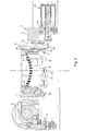
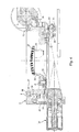
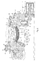
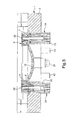
- FIGS. 1 to 6 show a molding device according to the invention, comprising their supports formed here by a first plate 1 'and a second plate 2 articulated with respect to each other.
- Each plate 1 and 2 comprises a body, respectively referenced 3 and 4, in which is formed a central recess.
- the two plates 1, 2 are articulated by means of a hinge 5 to allow the assembly formed by the two plates 1, 2 to fold on itself in a first position (see figure 1 on which the first plate 1 is above the second plate 2), to open like a book (see figures 3 and 4 which respectively represent the first plate 1 disposed to the right of the hinge 5 and the second plate disposed to the left of the hinge 5) or to fold on itself in a second position (see figure 5 on which the second plate 2 is above the first plate 1).
- the device further comprises a first shell holder 6.
- the latter comprises a body 7 having a central recess which is positioned vis-à-vis the central recess of the first plate 1.
- the first shell holder 6 further comprises an annular seat 8 forcibly fitted into the body 3 and surrounding said central recess, and an annular seal 9 attached to the body 7 so as to be positioned, in the absence of stress, against an internal surface of the seat 8.
- the seat 8 comprises a circular machining defining two surfaces 10, 11 (see FIG. figure 1 ) of wedging of a first shell 12, the annular seal 9 flush with one of said wedging surfaces 10, the one which is horizontal when the first plate 1 is in the position of the figure 1 (In the remainder of this description, the terms “horizontal” and “vertical” refer to the orientations as they are Figures 1 to 6 ).
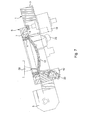
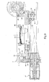
- the first shell holder 6 is disposed in the central recess of the first plate 1 and is mounted on a set of slides 42 (see figures 7 and 8 ) allowing the first shell holder 6 to move vertically relative to the first plate 1.
- This translational movement is controlled by a screw system 13 and nut 14.
- the screw 13 has a head 15 resting on a surface of the first shell holder 6 to be able to lift the latter, the head 15 being immobilized in rotation by a lug 16.
- the lug 16 stops only the rotation and does not prevent the holder-shell 6 to move away from the head 15 and therefore the first plate 1 according to the vertical.
- the nut 14 is mounted on bearings relative to the first plate 1 so as to rotate freely to raise or lower the screw 13.
- This nut 14 is further rotated by a gear 17 with concurrent axes for controlling the rotation of the nut 14 by a knob 18 manually operated.
- the translation of the first shell holder 6 can be controlled by a motor or a slave cylinder 19 (see figure 7 ).
- the first shell-holder 6 can thus take a position in which it bears against the first plate 1 ( figure 2 ) and a plurality of positions in which the first shell holder is away from the first plate 1 by a distance controlled by the knob 18 or the cylinder 19 ( figure 5 ).
- the annular seat 8 is intended to receive and put in position the first shell 12.
- the first shell holder 6 comprises for this purpose three clamping cylinders 20 (only two of these cylinders are visible in the sectional figures ) regularly arranged at 120 ° around the seat 8 and arranged obliquely so that their rods are able to urge the first shell 12 against the seat 8 ( figure 2 , 3 , 4 and 5 ) after deformation of the joint 9.
- the first shell holder 6 rests by gravity on the head 15 of the screw 13.
- the molding device comprises stop means constituted by a rod 21 protruding from the first shell holder 6 and having at its end a groove 22, and a cylinder 23 having a conical tip adapted to lock the rod 21 at the of its groove 22 ( figure 1 ).
- This locking position of the stop means corresponds to a stable position in which the first shell holder 6 is pressed against the first plate 1.
- these stop means are constituted by two double-acting cylinders 24 whose body 25 of each is integral with the first plate 1 and whose rod 26 of each is secured to the first shell-holder 6.
- These cylinders can be pressurized conventionally to ensure the function of plating of the first shell holder 6 against the first plate 1, in this case by placing in communication the small-section chamber of these cylinders with the source of pressure while the chamber with large section is put in communication with a return which is at atmospheric pressure.
- These cylinders can also be pressurized in the large-section chamber so as to play a role of compensation cylinder exposed later.
- the second stage 2 (visible more particularly to the figure 4 ), it also comprises a body 4 in which is formed a central recess occupied by a second shell holder 27, the second shell holder 27 itself having a central recess facing the central recess of the body 4, so that the second shell holder 27 is open from one side to the other, along its thickness.
- the second shell holder 27 comprises a set of three jaws 28 with concentric clamping intended for clamping and positioning a second shell 29, the positioning being performed, as for the first shell holder 6, by machining the jaws 28 defining for each of them two orthogonal surfaces 30, 31 (see FIG. figure 1 ). Note that when the plates 1 and 2 are vis-à-vis (right or left of the hinge 5), the surfaces 10 and 30 are parallel and the surfaces 11 and 31 are concentric.
- the rotation of the cam ring 32 is controlled by a jack 33 able to move, perpendicular to the plane of the drawing, a rod 34 attached to the cam ring 32 by a ball joint 35.
- the second shell holder 27 is mounted on bearings 36 so as to be rotatable relative to the body 4, about the vertical axis with respect to which the jaws 28 are concentric.
- This rotation of the second shell holder 27 relative to the second plate 2 can be controlled by a knob 37 which meshes with a conical wheel 38 secured to the second shell holder 27.
- the angular position of the second shell 29 around the vertical axis passing through its center (the center of concentricity of the jaws 28) can thus be precisely adjusted with the wheel 37.
- the stops 40, 41 define the horizontal rest positions of the first plate 1 when it is to the right of the hinge 5 and the second plate 2 when it is to the left of the hinge 5.
- the pivoting of the plates 1, 2 around the fixed hinge 5 is motorized, for example by respective wheels rotating about the axis of the hinge 5, the plates 1, 2 being each rotatably connected to one of said wheels .
- control means are provided for controlling the various members of the molding device that can be actuated automatically.
- a programmable logic controller or a microprocessor executing an appropriate program makes it possible to actuate in a precise order the pivoting of the two plates 1, 2, the movement of the concentric jaws 28, the translation of the first shell holder 6 with respect to the first plate 1 (in the case where a cylinder 19 is provided, figure 7 ), the control of the setting cylinders 20 and possibly double-acting cylinders 24.
- control means are also adapted to the control of any additional devices for gripping, depositing polymerizable material or polymerization, as described below.
- the molding device which has just been described operates as indicated below.
- the initial position of the device is that of the figure 1 , the two plates 1, 2 being superimposed on the right of the hinge 5.
- the stop means 21, 22, 23 (or the locking / compensation cylinders 24) being in their position where they retain the first shell holder 6 against the first plate 1, the first shell 12 is then loaded on the first plate 1 from above.
- This first shell 12 is brought by any gripping means, for example a suction cup, with its concavity facing downwards, that is to say towards the second plate 2, to be wedged in the annular seat 8, the cylinders of wedging 20 being retracted.
- the first shell 12 thus rests by gravity on the wedging surface 10 and is positioned laterally by the wedging surface 11.
- clamping cylinders 20 are then deployed and held in pressure so that their rods block the edges of the first shell 12 against the annular seat 8 thus deforming the seal 9.
- the first shell 12 having been put into position, the first plate 1 is pivoted to be placed to the right of the hinge 5 (see figure 2 ).
- the figure 3 represents the first plate 1 after the deposition of material.
- the second shell 29 is in fact brought from above, possibly by the same gripping means as the first shell 12, and is placed in position and clamped by the jaws 28, its face serving for molding, here its convex face, being turned to the top ( figure 4 ).
- the second shell 29 Once the second shell 29 is tightened, it may be necessary to adjust its angular position about a vertical axis, in the case where the second shell 29 is for molding a glass correcting astigmatism. This adjustment is made by an action on the wheel 37.
- the second plate 2 is then rotated to be superimposed on the first plate 1 on the right of the hinge 5.
- the second shell 29 is then facing and away from the bowl formed by the first shell 12.
- the first shell holder 6 is raised from the first plate by the action of the wheel 18 or the slave cylinder 19, so that the first shell 12 comes to contact the polymerizable material with the second shell 29, as shown in FIG. figure 5 .
- a napkin of material is formed by the surplus material at the periphery of the concave working surface of the first shell 12.
- the first and the second shell 12, 29 being in a predetermined position relative to the device, the rise of the first shell holder 6 can be controlled so that the spacing of the two shells 12, 29 corresponds precisely to the desired dimensions for the mold.
- a polymerization phase of the material is then carried out.
- projection means for example ultraviolet rays, are brought above and below the assembly formed by the two shells 12, 29 and the material.
- the shells 12, 29 are advantageously transparent for this purpose and the central recesses of the plates 1, 2 and shells 6, 27 allow wide accessibility to the rays, to ensure effective polymerization.
- the molding device is intended to accompany the removal of the material during the polymerization. Indeed, the material occupies less volume as it polymerizes, it exerts a force of attraction on the molding surfaces of the shells 12, 29.
- the first shell holder 6 being simply placed by gravity on the head 15 of the screw 13 (or on the rod of the slave cylinder 19), this attraction force is used to lift the first shell holder 6 so that the first shell 12 and the second shell 29 remain plated to the material during the withdrawal, and thus avoid delamination between the shells and the material.
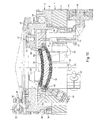
- the cylinders 24 of the figure 10 can also act as compensation jacks to facilitate the approximation of shells.
- the large-section chambers of these cylinders 24 are then pressurized so that the cylinders 24 exert on the first shell holder 6 a vertical force directed upwards and of an intensity slightly less than the weight of the first shell-holder 6, while the small section chambers are connected to a return that is at atmospheric pressure.
- a rigid block is formed by the shells 12, 29 and the solidified material.
- the concentric jaws 28 are then loosened and the second plate 2 is pivoted to its initial position while the first shell holder 6 is brought back and locked against the first plate 1.
- the first plate 1 is then also pivoted to its initial position, as shown in FIG. figure 6 , and the block formed of the shells 12, 29 and the solidified material is then evacuated from above, possibly by the same gripping means as for placing the shells 12, 29 in position and after the withdrawal of the clamping jacks 20.
- the ophthalmic lens thus molded and polymerized may follow other subsequent treatments where it will be demolded and prepared to be mounted on a support such as a spectacle frame.
- the figure 7 shows a variant of the step of depositing the polymerizable material in the bowl formed by the first shell 12 and the first shell holder 6.
- a material deposition nozzle 39 is schematically shown and, unlike the described step previously, the first plate 1 is inclined.
- the nozzle 39 begins by depositing a thread of material on an edge of the first shell 12 and, as the bowl is filled, the first plate 1 returns to its horizontal position, until the result of the figure 3 .
- This variant makes it possible to minimize the defects caused by the impact of the material against the first shell 12 during the pouring.
- the first plate 1 can also remain inclined for the following steps.
- the second plate 2 will then be superimposed on the first plate 1 so as to be itself inclined, which allows the second shell 29, during the step of bringing the first shell 12 and the second shell 29 closer to each other. come into contact with the material starting with an edge rather than the center.
- the figures 9 and 10 represent a variant in which the molding is performed with an annular seal 40, fixed on the second shell 29 beforehand or just after being clamped by the concentric jaws 28 (see figure 9 ).
- the molding can be performed other than flat, for example vertically.
- the two plates are then in their relative molding position and in a vertical orientation, an annular seal of the type shown in FIGS. figures 9 and 10 being provided between the two shells.
- the material is injected through an orifice in the seal, while a vent is provided, also in the seal, on the upper part thereof.
- the supports are constituted by elements other than plates.
- the molding of other types of optical lenses may be considered, for example binocular lenses or the like.
Landscapes
- Engineering & Computer Science (AREA)
- Health & Medical Sciences (AREA)
- Manufacturing & Machinery (AREA)
- Ophthalmology & Optometry (AREA)
- Mechanical Engineering (AREA)
- Casting Or Compression Moulding Of Plastics Or The Like (AREA)
- Eyeglasses (AREA)
- Moulds For Moulding Plastics Or The Like (AREA)
- Prostheses (AREA)
Claims (17)
- Vorrichtung zum Erhalten einer optischen Linse, insbesondere einer ophthalmischen Linse, ausgehend von einem polymerisierbaren Material, umfassend eine erste Gusskokille (12), einer zweite Gusskokille (29) und Haltemittel der ersten (12) und zweiten (29) Gusskokille in einer vorbestimmten Gussposition, in welcher sie in einem Abstand zueinander in einer vorbestimmten relativen Position und entlang einer vorbestimmten Ausrichtung angeordnet sind; dadurch gekennzeichnet, dass die Haltemittel umfassen:- einen ersten Kokillenträger (6), dazu ausgelegt die erste Kokille (12) in einer vorbestimmten Position bezüglich des ersten Kokillenträgers (6) zu immobilisieren; und einen zweiten Kokillenträger (27), dazu ausgelegt die zweite Kokille (29) in einer vorbestimmten Position bezüglich des zweiten Kokillenträgers (27) zu immobilisieren;- eine erste Halterung (1), an welcher der erste Kokillenträger (6) angeordnet ist, und eine zweite Halterung (2), an welcher der zweite Kokillenträger (27) angeordnet ist, wobei die erste Halterung (1) und die zweite Halterung (2) bezüglich einander um ein festes Gelenk (5) gelenkig verbunden sind, gegenüber dem jede der ersten Halterung (1) und der zweiten Halterung (2) schwenken kann;mit der ersten Halterung (1) und der zweite Halterung (2), welche eine erste relative Position ermöglichen, in welcher sie aneinander anliegend sind, während die erste Kokille (12) und die zweite Kokille (29) in der vorbestimmten relativen Position sind, und welche eine zweite relative Position ermöglichen, in welcher die erste Halterung (1) und die zweite Halterung (2) sich bezüglich der ersten relativen Position voneinander durch eine relative Schwenkbewegung entfernt haben, wobei die Vorrichtung eine Gusskonfiguration ermöglicht, in welcher die erste Halterung (1) und die zweite Halterung (2) in der ersten relativen Position sind, während die ersten Kokille (12) und die zweite Kokille (29) gemäß der vorbestimmten Ausrichtung sind;
wobei die Vorrichtung zudem ermöglicht:
eine erste Konfiguration, in welcher die erste Halterung (1) und die zweite Halterung (2) in der ersten relativen Position sind und jeweils flach bezüglich der ersten Halterung (1) ausgerichtet sind, welche oberhalb der zweiten Halterung (2) ist; und eine zweite Konfiguration, in welcher die erste Halterung (1) und die zweite Halterung (2) in der ersten relativen Position sind und jeweils flach bezüglich der zweiten Halterung (2), welche über der ersten Halterung (1) befindlich ist, ausgerichtet sind. - Vorrichtung nach Anspruch 1, dadurch gekennzeichnet, dass die vorbestimmte Ausrichtung eine flache Ausrichtung ist.
- Vorrichtung nach Anspruch 1 oder 2, dadurch gekennzeichnet, dass die erste Halterung (1) und die zweite Halterung (2) in der zweiten relativen Position einander entgegengesetzt sind.
- Vorrichtung nach einem der Ansprüche 1 bis 3, dadurch gekennzeichnet, dass sie einer offene Konfiguration ermöglicht, in welcher die ersten Halterung (1) und die zweite Halterung (2) in der zweiten relativen Position jeweils flach sind.
- Vorrichtung nach Anspruch 4, dadurch gekennzeichnet, dass die jeweiligen Seiten der ersten Halterung (1) und der zweiten Halterung (2), welcher in der ersten relativen Position einander gegenüber stehen, in der offen Konfiguration jeweils nach oben schauen.
- Vorrichtung nach einem der Ansprüche 1 bis 5, dadurch gekennzeichnet, dass die erste Halterung (1) und die zweite Halterung (2) jeweils eine Referenzfläche aufweisen,
wobei die Referenzflächen aneinander anliegend angeordnet sind, wenn die ersten Halterung (1) und die zweite Halterung (2) in der ersten relativen Position aneinander anliegend sind. - Vorrichtung nach einem der Ansprüche 1 bis 6, dadurch gekennzeichnet, dass die erste Halterung (1) und die zweite Halterung (2) mit einem Scharnier (5) verbunden sind.
- Vorrichtung nach einem der Ansprüche 1 bis 7, dadurch gekennzeichnet, dass sie zudem zwei Rollen umfasst, welche zu der Gelenkachse der beiden Halterungen (1,2) senkrecht sind und welche jeweils beiderseits dieses Gelenks befindlich sind, derart, dass die Achse jeder der Rollen mit der Gelenkachse der beiden Halterungen (1,2) zusammenfällt, wobei eine erste der Rollen drehbar mit der ersten Halterung (1) verbunden ist und eine zweite der Rollen drehbar mit er zweiten Halterung (2) verbunden ist, so dass die Drehung der ersten Rolle ein Schwenken der ersten Halterung (1) relativ zu der zweiten Halterung (2) antreibt und dass die Drehung der zweiten Rolle eine Schwenken der zweiten Halterung (2) relativ zu der ersten Halterung (1) antreibt.
- Vorrichtung nach Anspruch 8, dadurch gekennzeichnet, dass die Rollen gezahnte Rollen sind, die dazu geeignet sind, jeweils durch ein mit einem Motor verbundenes Ritzel oder eine mit einem Spindel verbundene Zahnstange angetrieben zu werden.
- Vorrichtung nach einem der Ansprüche 1 bis 9, dadurch gekennzeichnet, dass der erste Kokillenträger (6) gleitend mit der ersten Halterung (1) zusammenwirkt, um, wenn die erste Kokille (12) und die zweite Kokille (29) in der Gussposition sind, eine gegenseitige Entfernungs- oder Annäherungs-Bewegung der ersten Kokille (12) und der zweiten Kokille (29) zu ermöglichen.
- Vorrichtung nach Anspruch 10, dadurch gekennzeichnet, dass das Gleiten des ersten Kokillenträgers (6) bezüglich der ersten Halterung (1) durch eine Spindelantrieb (19) gesteuert ist, wobei der Spindelantrieb (19) zudem ermöglicht, den ersten Kokillenträger (6) relativ zu der ersten Halterung (1) zu immobilisieren, mit Ausnahme der Annäherungsbewegung zwischen dem ersten Kokillenträger und dem zweiten Kokillenträger (27).
- Vorrichtung nach einem der Ansprüche 1 bis 11, dadurch gekennzeichnet, dass der zweite Kokillenträger (27) drehbar beweglich bezüglich der zweiten Halterung (2) ist.
- Vorrichtung nach einem der Ansprüche 1 bis 12, dadurch gekennzeichnet, dass die vorbestimmte Position der ersten Kokille (12) bezüglich des ersten Kokillenträgers (6) durch einen ringförmigen Sitz (8) definiert ist, welcher dazu ausgelegt ist, die erste Kokille (12) entlang zweie orthogonaler Richtungen zu verkanten.
- Vorrichtung nach Anspruch 13, dadurch gekennzeichnet, dass der erste Kokillenträger (6) zumindest eine Spindel (24) umfasst, welche dazu ausgelegt ist, die erste Kokille (12) gegen der ringförmigen Sitz (8) zu halten.
- Vorrichtung nach einem der Ansprüche 1 bis 14, dadurch gekennzeichnet, dass die vorbestimmte Position der zweiten Kokille (29) bezüglich des zweiten Kokilleträgers (27) durch einen Satz konzentrischen Spannbacken (28) definiert ist, welche zum Einspannen der zweiten Kokille (29) an ihrem Umfang ausgelegt sind.
- Vorrichtung nach Anspruch 15, dadurch gekennzeichnet, dass das Öffnen und Schlie-ßen der Spannbacken (28) durch einen Nockenkranz (32) gesteuert wird.
- Verfahren zum Erhalten einer optischen Linse, insbesondere einer ophthalmischen Linse, ausgehend von einem polymerisierbaren Material, welches die Vorrichtung nach einem der Ansprüche 1 bis 16 verwendet, wobei das Verfahren dadurch gekennzeichnet ist, dass es umfasst:- einen Polymerisierungsschritt des zwischen der ersten Kokille (12) und der zweiten Kokille (29) befindlichen polymerisierbaren Materials, wenn die Vorrichtung in der zweiten Konfiguration ist, so dass durch die Kokillen (12, 29) und das erhärtete Material ein starrer Block ausgebildet wird;- einen Übergangsschritt von der zweiten Konfiguration in die erste Konfiguration der Vorrichtung; danach- einen Entnahmeschritt des starren Blocks, wenn die Vorrichtung in der ersten Konfiguration ist.
Applications Claiming Priority (2)
| Application Number | Priority Date | Filing Date | Title |
|---|---|---|---|
| FR0306988A FR2856006B1 (fr) | 2003-06-11 | 2003-06-11 | Dispositif a supports articules pour le moulage d'une lentille optique, en particulier une lentille ophtalmique |
| PCT/FR2004/001432 WO2004110730A1 (fr) | 2003-06-11 | 2004-06-09 | Dispositif a supports articules pour le moulage d’une lentille optique, en particulier une lentille ophtalmique |
Publications (2)
| Publication Number | Publication Date |
|---|---|
| EP1631444A1 EP1631444A1 (de) | 2006-03-08 |
| EP1631444B1 true EP1631444B1 (de) | 2008-03-26 |
Family
ID=33484330
Family Applications (1)
| Application Number | Title | Priority Date | Filing Date |
|---|---|---|---|
| EP04767298A Expired - Lifetime EP1631444B1 (de) | 2003-06-11 | 2004-06-09 | Mit schwenkbaren stützen versehene vorrichtung zum formen einer optischen linse, insbesondere einer ophthalmischen linse und verfahren zur deren benutzung |
Country Status (7)
| Country | Link |
|---|---|
| US (1) | US7607910B2 (de) |
| EP (1) | EP1631444B1 (de) |
| JP (1) | JP4477633B2 (de) |
| AT (1) | ATE390268T1 (de) |
| DE (1) | DE602004012742T2 (de) |
| FR (1) | FR2856006B1 (de) |
| WO (1) | WO2004110730A1 (de) |
Families Citing this family (3)
| Publication number | Priority date | Publication date | Assignee | Title |
|---|---|---|---|---|
| US7585167B2 (en) * | 2004-12-30 | 2009-09-08 | Bausch + Lomb Incorporated | Core locking assembly and method for orientation of asymmetric tooling |
| TWI263067B (en) * | 2005-02-18 | 2006-10-01 | Asia Optical Co Inc | Fusion method of transparent body and light shield sheet thereof |
| CN102744899B (zh) * | 2012-07-12 | 2014-08-13 | 临海市劳尔机械有限公司 | 镜片自动制模机的自动纠正装置 |
Family Cites Families (15)
| Publication number | Priority date | Publication date | Assignee | Title |
|---|---|---|---|---|
| GB847797A (en) * | 1955-12-30 | 1960-09-14 | Combined Optical Ind Ltd | Improvements in or relating to the casting of synthetic resins |
| DE2455888A1 (de) * | 1974-11-16 | 1976-05-26 | Ludwig Dr Kamlander | Verfahren und form zur kontinuierlichen herstellung von linsenrohlingen |
| US4474355A (en) * | 1977-06-27 | 1984-10-02 | Martin Greshes | Apparatus for molding optical plastic lenses of the standard and bifocal type |
| FR2465562A1 (fr) * | 1979-09-26 | 1981-03-27 | Essilor Int | Appareil de blocage pour fixer un bloc metallique sur la face finie d'une ebauche semi-finie de lentille ophtalmique |
| US6800225B1 (en) * | 1994-07-14 | 2004-10-05 | Novartis Ag | Process and device for the manufacture of mouldings and mouldings manufactured in accordance with that process |
| JP3368022B2 (ja) * | 1993-12-01 | 2003-01-20 | キヤノン株式会社 | カメラ |
| US5548352A (en) * | 1994-01-19 | 1996-08-20 | Coherent, Inc. | Anti-astigmatic ophthalmic contact lens for use in performing laser surgery |
| JP2001512383A (ja) * | 1997-02-20 | 2001-08-21 | テクノロジー リソース インターナショナル コーポレイション | レンズ形成のためのガスケット |
| JP3607493B2 (ja) * | 1998-03-02 | 2005-01-05 | 山本光学株式会社 | レンズの製造方法及びレンズの製造装置 |
| EP0941829B1 (de) * | 1998-03-10 | 2002-12-11 | Novartis AG | Formwerkzeug zur Herstellung von Präzisionsteilen, insbesondere von Kontaktlinsen |
| WO2000059713A1 (en) * | 1999-03-31 | 2000-10-12 | Novartis Ag | Mold for forming contact lenses |
| US6918267B2 (en) * | 2001-08-27 | 2005-07-19 | Hoya Corporation | Press molding apparatus and press molding method |
| US6872335B2 (en) * | 2002-03-12 | 2005-03-29 | Technology Resource International Corporation | Method and apparatus for holding a mold assembly and molding an optical lens using the same |
| FR2837419B1 (fr) * | 2002-03-19 | 2006-11-24 | Essilor Int | Procede pour l'obtention d'une lentille optique ainsi que joint et dispositif pour sa mise en oeuvre |
| FR2856005B1 (fr) * | 2003-06-11 | 2007-03-23 | Essilor Int | Procede et dispositif de moulage d'une lentille optique, en particulier une lentille ophtalmique |
-
2003
- 2003-06-11 FR FR0306988A patent/FR2856006B1/fr not_active Expired - Fee Related
-
2004
- 2004-06-09 EP EP04767298A patent/EP1631444B1/de not_active Expired - Lifetime
- 2004-06-09 AT AT04767298T patent/ATE390268T1/de not_active IP Right Cessation
- 2004-06-09 DE DE602004012742T patent/DE602004012742T2/de not_active Expired - Lifetime
- 2004-06-09 US US10/558,399 patent/US7607910B2/en not_active Expired - Fee Related
- 2004-06-09 JP JP2006516275A patent/JP4477633B2/ja not_active Expired - Lifetime
- 2004-06-09 WO PCT/FR2004/001432 patent/WO2004110730A1/fr not_active Ceased
Also Published As
| Publication number | Publication date |
|---|---|
| WO2004110730A1 (fr) | 2004-12-23 |
| FR2856006A1 (fr) | 2004-12-17 |
| US7607910B2 (en) | 2009-10-27 |
| US20070013091A1 (en) | 2007-01-18 |
| FR2856006B1 (fr) | 2007-03-23 |
| EP1631444A1 (de) | 2006-03-08 |
| ATE390268T1 (de) | 2008-04-15 |
| DE602004012742D1 (de) | 2008-05-08 |
| DE602004012742T2 (de) | 2009-04-16 |
| JP2006527108A (ja) | 2006-11-30 |
| JP4477633B2 (ja) | 2010-06-09 |
| WO2004110730B1 (fr) | 2005-03-17 |
Similar Documents
| Publication | Publication Date | Title |
|---|---|---|
| EP2723529A1 (de) | Vorrichtung zum halten einer turbomaschinenschaufel zur bearbeitung | |
| EP2661352B1 (de) | Vorrichtung zum blasformen von behältern | |
| WO2014068247A2 (fr) | Procédé de fabrication de lentilles optiques et ensemble pour la fabrication de telles lentilles | |
| EP2914400A2 (de) | Verfahren zur maschinellen herstellung von kontaktlinsen | |
| EP1636018B1 (de) | Verfahren und vorrichtung zum formen einer optischen linse, insbesondere einer ophthalmischen linse | |
| EP1631444A1 (de) | Mit schwenkbaren stützen versehene vorrichtung zum formen einer optischen linse, insbesondere einer ophthalmischen linse | |
| EP2624985B1 (de) | Form zur herstellung von teilen mittels wachsinjektion | |
| FR2720679A1 (fr) | Bras de transfert et machine de fabrication de bouteilles à partir de préforme utilisant un tel bras. | |
| EP0094881B1 (de) | Bandsäge und Kasten für die Unterstützung des Blattes einer solchen Säge | |
| FR3081747A1 (fr) | Outil de moulage comprenant une cale de maintien actionnee par du gaz comprime | |
| BE1005071A5 (fr) | Appareil de moulage de resine synthetique. | |
| FR2938505A1 (fr) | Outillage a elements articules equipe d'un dispositif de verrouillage | |
| CH339528A (fr) | Lentille multifocale, procédé pour sa fabrication et installation pour la mise en oeuvre de ce procédé | |
| EP0594475B1 (de) | Ausstellschere für Kippfenster | |
| CH330531A (fr) | Procédé pour contrôler le profil d'une pièce et installation pour la mise en oeuvre de ce procédé | |
| FR3041293A1 (fr) | Dispositif d'articulation d'un siege | |
| FR2925886A1 (fr) | Dispositif de prehension de recipient par le col et application a un remplissage ponderal | |
| FR3081373A1 (fr) | Machine de pliage de decoupe a butees inferieures motorisees | |
| FR2705605A1 (fr) | Dispositif de démontage d'une porte de véhicule automobile, par soulèvement axial à l'aide d'un robot. | |
| EP1679170A1 (de) | Schleudergussvorrichtung zur Herstellung von Formstücken aus Kunststoff, mit einem Drehtisch für Formwerkzeuge und einem Drehtisch für Pulverbehälter | |
| FR2458366A1 (fr) | Machine pour l'ecorcage de billes de bois | |
| CH392402A (fr) | Dispositif pour mettre un mobile d'horlogerie en place entre deux paliers coaxiaux | |
| FR3063446A1 (fr) | Ouvreur de moule pour la fabrication de modeles pour procede de moulage a modele perdu | |
| BE421726A (de) | ||
| FR2555473A1 (fr) | Mecanisme de bridage et de positionnement pour une machine de renforcement a poudre |
Legal Events
| Date | Code | Title | Description |
|---|---|---|---|
| PUAI | Public reference made under article 153(3) epc to a published international application that has entered the european phase |
Free format text: ORIGINAL CODE: 0009012 |
|
| 17P | Request for examination filed |
Effective date: 20051031 |
|
| AK | Designated contracting states |
Kind code of ref document: A1 Designated state(s): AT BE BG CH CY CZ DE DK EE ES FI FR GB GR HU IE IT LI LU MC NL PL PT RO SE SI SK TR |
|
| 17Q | First examination report despatched |
Effective date: 20060706 |
|
| DAX | Request for extension of the european patent (deleted) | ||
| RTI1 | Title (correction) |
Free format text: DEVICE PROVIDED WITH PIVOTABLE SUPPORTS FOR MOULDING AN OPTICAL LENS, IN PARTICULAR AN OPHTHALMIC LENS AND METHOD FOR ITS USE |
|
| GRAP | Despatch of communication of intention to grant a patent |
Free format text: ORIGINAL CODE: EPIDOSNIGR1 |
|
| GRAS | Grant fee paid |
Free format text: ORIGINAL CODE: EPIDOSNIGR3 |
|
| GRAA | (expected) grant |
Free format text: ORIGINAL CODE: 0009210 |
|
| AK | Designated contracting states |
Kind code of ref document: B1 Designated state(s): AT BE BG CH CY CZ DE DK EE ES FI FR GB GR HU IE IT LI LU MC NL PL PT RO SE SI SK TR |
|
| REG | Reference to a national code |
Ref country code: GB Ref legal event code: FG4D Free format text: NOT ENGLISH |
|
| REG | Reference to a national code |
Ref country code: CH Ref legal event code: EP Ref country code: IE Ref legal event code: FG4D Free format text: LANGUAGE OF EP DOCUMENT: FRENCH |
|
| REF | Corresponds to: |
Ref document number: 602004012742 Country of ref document: DE Date of ref document: 20080508 Kind code of ref document: P |
|
| PG25 | Lapsed in a contracting state [announced via postgrant information from national office to epo] |
Ref country code: FI Free format text: LAPSE BECAUSE OF FAILURE TO SUBMIT A TRANSLATION OF THE DESCRIPTION OR TO PAY THE FEE WITHIN THE PRESCRIBED TIME-LIMIT Effective date: 20080326 |
|
| PG25 | Lapsed in a contracting state [announced via postgrant information from national office to epo] |
Ref country code: AT Free format text: LAPSE BECAUSE OF FAILURE TO SUBMIT A TRANSLATION OF THE DESCRIPTION OR TO PAY THE FEE WITHIN THE PRESCRIBED TIME-LIMIT Effective date: 20080326 |
|
| NLV1 | Nl: lapsed or annulled due to failure to fulfill the requirements of art. 29p and 29m of the patents act | ||
| PG25 | Lapsed in a contracting state [announced via postgrant information from national office to epo] |
Ref country code: SI Free format text: LAPSE BECAUSE OF FAILURE TO SUBMIT A TRANSLATION OF THE DESCRIPTION OR TO PAY THE FEE WITHIN THE PRESCRIBED TIME-LIMIT Effective date: 20080326 Ref country code: PL Free format text: LAPSE BECAUSE OF FAILURE TO SUBMIT A TRANSLATION OF THE DESCRIPTION OR TO PAY THE FEE WITHIN THE PRESCRIBED TIME-LIMIT Effective date: 20080326 |
|
| REG | Reference to a national code |
Ref country code: IE Ref legal event code: FD4D |
|
| PG25 | Lapsed in a contracting state [announced via postgrant information from national office to epo] |
Ref country code: CZ Free format text: LAPSE BECAUSE OF FAILURE TO SUBMIT A TRANSLATION OF THE DESCRIPTION OR TO PAY THE FEE WITHIN THE PRESCRIBED TIME-LIMIT Effective date: 20080326 Ref country code: SK Free format text: LAPSE BECAUSE OF FAILURE TO SUBMIT A TRANSLATION OF THE DESCRIPTION OR TO PAY THE FEE WITHIN THE PRESCRIBED TIME-LIMIT Effective date: 20080326 Ref country code: SE Free format text: LAPSE BECAUSE OF FAILURE TO SUBMIT A TRANSLATION OF THE DESCRIPTION OR TO PAY THE FEE WITHIN THE PRESCRIBED TIME-LIMIT Effective date: 20080626 Ref country code: ES Free format text: LAPSE BECAUSE OF FAILURE TO SUBMIT A TRANSLATION OF THE DESCRIPTION OR TO PAY THE FEE WITHIN THE PRESCRIBED TIME-LIMIT Effective date: 20080707 Ref country code: PT Free format text: LAPSE BECAUSE OF FAILURE TO SUBMIT A TRANSLATION OF THE DESCRIPTION OR TO PAY THE FEE WITHIN THE PRESCRIBED TIME-LIMIT Effective date: 20080901 |
|
| PG25 | Lapsed in a contracting state [announced via postgrant information from national office to epo] |
Ref country code: NL Free format text: LAPSE BECAUSE OF FAILURE TO SUBMIT A TRANSLATION OF THE DESCRIPTION OR TO PAY THE FEE WITHIN THE PRESCRIBED TIME-LIMIT Effective date: 20080326 Ref country code: RO Free format text: LAPSE BECAUSE OF FAILURE TO SUBMIT A TRANSLATION OF THE DESCRIPTION OR TO PAY THE FEE WITHIN THE PRESCRIBED TIME-LIMIT Effective date: 20080326 |
|
| BERE | Be: lapsed |
Owner name: ESSILOR INTERNATIONAL (COMPAGNIE GENERALE D'OPTIQ Effective date: 20080630 |
|
| PG25 | Lapsed in a contracting state [announced via postgrant information from national office to epo] |
Ref country code: IE Free format text: LAPSE BECAUSE OF FAILURE TO SUBMIT A TRANSLATION OF THE DESCRIPTION OR TO PAY THE FEE WITHIN THE PRESCRIBED TIME-LIMIT Effective date: 20080326 Ref country code: DK Free format text: LAPSE BECAUSE OF FAILURE TO SUBMIT A TRANSLATION OF THE DESCRIPTION OR TO PAY THE FEE WITHIN THE PRESCRIBED TIME-LIMIT Effective date: 20080326 Ref country code: MC Free format text: LAPSE BECAUSE OF NON-PAYMENT OF DUE FEES Effective date: 20080630 |
|
| PLBE | No opposition filed within time limit |
Free format text: ORIGINAL CODE: 0009261 |
|
| REG | Reference to a national code |
Ref country code: CH Ref legal event code: PL |
|
| STAA | Information on the status of an ep patent application or granted ep patent |
Free format text: STATUS: NO OPPOSITION FILED WITHIN TIME LIMIT |
|
| 26N | No opposition filed |
Effective date: 20081230 |
|
| PG25 | Lapsed in a contracting state [announced via postgrant information from national office to epo] |
Ref country code: BE Free format text: LAPSE BECAUSE OF NON-PAYMENT OF DUE FEES Effective date: 20080630 |
|
| PG25 | Lapsed in a contracting state [announced via postgrant information from national office to epo] |
Ref country code: EE Free format text: LAPSE BECAUSE OF FAILURE TO SUBMIT A TRANSLATION OF THE DESCRIPTION OR TO PAY THE FEE WITHIN THE PRESCRIBED TIME-LIMIT Effective date: 20080326 Ref country code: BG Free format text: LAPSE BECAUSE OF FAILURE TO SUBMIT A TRANSLATION OF THE DESCRIPTION OR TO PAY THE FEE WITHIN THE PRESCRIBED TIME-LIMIT Effective date: 20080626 |
|
| PG25 | Lapsed in a contracting state [announced via postgrant information from national office to epo] |
Ref country code: CH Free format text: LAPSE BECAUSE OF NON-PAYMENT OF DUE FEES Effective date: 20080630 Ref country code: LI Free format text: LAPSE BECAUSE OF NON-PAYMENT OF DUE FEES Effective date: 20080630 |
|
| PG25 | Lapsed in a contracting state [announced via postgrant information from national office to epo] |
Ref country code: IT Free format text: LAPSE BECAUSE OF FAILURE TO SUBMIT A TRANSLATION OF THE DESCRIPTION OR TO PAY THE FEE WITHIN THE PRESCRIBED TIME-LIMIT Effective date: 20080326 |
|
| PG25 | Lapsed in a contracting state [announced via postgrant information from national office to epo] |
Ref country code: CY Free format text: LAPSE BECAUSE OF FAILURE TO SUBMIT A TRANSLATION OF THE DESCRIPTION OR TO PAY THE FEE WITHIN THE PRESCRIBED TIME-LIMIT Effective date: 20080326 |
|
| PG25 | Lapsed in a contracting state [announced via postgrant information from national office to epo] |
Ref country code: LU Free format text: LAPSE BECAUSE OF NON-PAYMENT OF DUE FEES Effective date: 20080609 Ref country code: HU Free format text: LAPSE BECAUSE OF FAILURE TO SUBMIT A TRANSLATION OF THE DESCRIPTION OR TO PAY THE FEE WITHIN THE PRESCRIBED TIME-LIMIT Effective date: 20080927 |
|
| PG25 | Lapsed in a contracting state [announced via postgrant information from national office to epo] |
Ref country code: TR Free format text: LAPSE BECAUSE OF FAILURE TO SUBMIT A TRANSLATION OF THE DESCRIPTION OR TO PAY THE FEE WITHIN THE PRESCRIBED TIME-LIMIT Effective date: 20080326 |
|
| PG25 | Lapsed in a contracting state [announced via postgrant information from national office to epo] |
Ref country code: GR Free format text: LAPSE BECAUSE OF FAILURE TO SUBMIT A TRANSLATION OF THE DESCRIPTION OR TO PAY THE FEE WITHIN THE PRESCRIBED TIME-LIMIT Effective date: 20080627 |
|
| PGFP | Annual fee paid to national office [announced via postgrant information from national office to epo] |
Ref country code: GB Payment date: 20120619 Year of fee payment: 9 |
|
| GBPC | Gb: european patent ceased through non-payment of renewal fee |
Effective date: 20130609 |
|
| PG25 | Lapsed in a contracting state [announced via postgrant information from national office to epo] |
Ref country code: GB Free format text: LAPSE BECAUSE OF NON-PAYMENT OF DUE FEES Effective date: 20130609 |
|
| REG | Reference to a national code |
Ref country code: FR Ref legal event code: PLFP Year of fee payment: 13 |
|
| REG | Reference to a national code |
Ref country code: FR Ref legal event code: PLFP Year of fee payment: 14 |
|
| REG | Reference to a national code |
Ref country code: DE Ref legal event code: R082 Ref document number: 602004012742 Country of ref document: DE Representative=s name: 24IP LAW GROUP SONNENBERG FORTMANN, DE Ref country code: DE Ref legal event code: R081 Ref document number: 602004012742 Country of ref document: DE Owner name: ESSILOR INTERNATIONAL, FR Free format text: FORMER OWNER: ESSILOR INTERNATIONAL (COMPAGNIE GENERALE D'OPTIQUE), CHARENTON-LE-PONT, FR |
|
| REG | Reference to a national code |
Ref country code: FR Ref legal event code: PLFP Year of fee payment: 15 |
|
| REG | Reference to a national code |
Ref country code: FR Ref legal event code: TP Owner name: ESSILOR INTERNATIONAL, FR Effective date: 20180601 |
|
| P01 | Opt-out of the competence of the unified patent court (upc) registered |
Effective date: 20230525 |
|
| PGFP | Annual fee paid to national office [announced via postgrant information from national office to epo] |
Ref country code: FR Payment date: 20230626 Year of fee payment: 20 Ref country code: DE Payment date: 20230626 Year of fee payment: 20 |
|
| REG | Reference to a national code |
Ref country code: DE Ref legal event code: R071 Ref document number: 602004012742 Country of ref document: DE |