EP1631358B1 - Dauerbrandsichere flammensperre - Google Patents
Dauerbrandsichere flammensperre Download PDFInfo
- Publication number
- EP1631358B1 EP1631358B1 EP04738609A EP04738609A EP1631358B1 EP 1631358 B1 EP1631358 B1 EP 1631358B1 EP 04738609 A EP04738609 A EP 04738609A EP 04738609 A EP04738609 A EP 04738609A EP 1631358 B1 EP1631358 B1 EP 1631358B1
- Authority
- EP
- European Patent Office
- Prior art keywords
- flame arrester
- flame
- section
- concentric
- passage gaps
- Prior art date
- Legal status (The legal status is an assumption and is not a legal conclusion. Google has not performed a legal analysis and makes no representation as to the accuracy of the status listed.)
- Expired - Lifetime
Links
Images
Classifications
-
- A—HUMAN NECESSITIES
- A62—LIFE-SAVING; FIRE-FIGHTING
- A62C—FIRE-FIGHTING
- A62C4/00—Flame traps allowing passage of gas but not of flame or explosion wave
-
- A—HUMAN NECESSITIES
- A62—LIFE-SAVING; FIRE-FIGHTING
- A62C—FIRE-FIGHTING
- A62C4/00—Flame traps allowing passage of gas but not of flame or explosion wave
- A62C4/02—Flame traps allowing passage of gas but not of flame or explosion wave in gas-pipes
Definitions
- the invention relates to a flameproof flame arrestor having a flow-restricting cross-sectional area in which there is a flame arrester insert having a flame arrestor assembly having a plurality of passageway securing passageways ensuring continuous fire safety formed by a corrugated metal strip co-wound with a smooth metal strip.
- Durable flame arresters of this type are used to vent potentially explosive systems. They must be designed so that it can withstand fires in the event of ignition of the effluent gas or product / vapor / air mixtures, thus permitting flaring of the mixtures for an indefinite period of time, without it being possible for a flashover to occur in the part of the plant to be protected.
- a flame-retardant flame arrester of this kind is, for example, by DE 1 041 423 known.
- the flow cross-section is annular and encloses a hollow core piece, flows through the ambient air, which is sucked by the flame during flaring of the gas or vapor from the environment and used to cool a serving as a flame barrier ring grate.
- disk-shaped flame arresters can only be used up to a certain maximum diameter and ring-shaped flame arresters must not exceed a certain width of the ring. Therefore, in many cases, the size of the flame arrester can be difficult because the flame arrestor has to be adapted to the connection of the pipe and for mixtures with high ignitability (explosion group IIB or IIC), where very narrow flame-extinguishing gaps in the flame arrester are necessary.
- the width or the inner and / or outer diameter of the flame arrester is dimensioned so that a desired flow rate is achieved.
- US 5,336,083 discloses a detonation arrestor assembly constructed in multiple parts. As seen in the flow direction, it consists of a flame-extinguishing material which has a multiplicity of passage gaps effecting flame extinction. This material is formed by suitable bulk materials. In the direction of flow on both sides of the flame-extinguishing material are detonation brakes in the form of stacked plates having slit-shaped spaces through which the flame front must pass in order to get to the flame-extinguishing material in the middle. In a variant of the detonation brakes they do not consist of rectilinear plates, but spirally wound bands, the slot-shaped intermediate spaces required for the gas passage are ensured by an interposed wavy band as a spacer.
- the detonation brakes have the function of intercepting the detonation front and dividing it into individual detonation fronts.
- the disclosed detonation detent order is not endurance-proof but is designed to provide only temporary fire safety. This function takes over the center arranged bulk material with the flame-extinguishing fine gaps, which is evenly distributed over the entire flow area.
- AT 250 544 disclose a flame arrester having passageways formed by co-winding helically a smooth metal strip with a metal strip provided with bent tabs. This results in a uniform structure of the flame arrester with the passage columns.
- the region of the flame arrester with the passage gaps is bounded radially outwardly by a ring which may be solid or is formed by the fact that the smooth metal strip is longer than the metal strip provided with the bent-out tongues, so that the smooth metal strip penetrates the radially outer ring tightly adjacent turns without passage column forms the reinforcing ring 7 of a fuse body.
- the problem of endurance safety and heat dissipation is not addressed.
- the invention has for its object to provide a flameproof flame arrester in the form of a disc-shaped or annular flame arrester, with the endurance of a fire endangered heating of the flame arrester can be avoided in a simple manner.
- a flameproof barrier of the type mentioned above is inventively characterized in that within the modaquerites at least two Flammensperran extract are arranged with the passage gaps, between which there is a cooling ring forming a concentric section, which is solid without passage gaps.
- the concentric portion may be formed as an annular portion and thus the flow area in a plurality of annular Divide flow areas.
- a centrally arranged core can be provided.
- the cross-sectional area of the flame arrester insert formed with the passage gaps is larger than the cross-sectional area without passage gaps.
- the area without through-gaps is between 35 and 40% of the total area of a ring flame arrester and between 25 and 35% of the cross-sectional area of a disc flame arrester.
- the inventively provided at least one concentric section thus divides the surface of the disk-shaped flame arrester, whereby an inadmissible heating in the radially inner region of the flame arrestor is avoided.
- the at least one concentric portion may be formed of a heat-insulating material to limit the area in which forms a flame on the surface of the flame arrester, and to reduce heating in this area. But it is also possible and in many cases preferred to form the concentric portion of a good heat conductive material to accomplish in the concentric region improved heat dissipation within the flow area of the flame arrester.
- a centrally arranged core as a concentric section which is formed of good heat conducting material, cause improved heat dissipation in the center of fürströmquerschnits and let, for example, a disc-shaped flame arrest to a flame arrester, whose passage gaps are arranged on an annular surface.
- the concentric portion may be formed from a smoothly wound tightly wound smooth metal strip. This is particularly advantageous if the passage gaps of the flow cross-section are formed in a manner known per se by a corrugated metal strip spirally wound together with a smooth metal strip. While maintaining the winding operation, the supply of the corrugated metal strip to the winding device can be stopped to form a concentric section according to the invention and only the smooth metal strip are wound until regularly after a certain thickness of the resulting concentric section of the corrugated metal strip is fed back to the smooth metal strip , around to form an outer annular portion around the concentric portion.
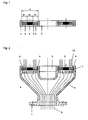
- FIG. 1 shows a first embodiment of a flame arrester according to the invention, which is annular. Accordingly, a housing 1 is provided which has an annular cage for cage forms an annular flow area 2. A middle part 3 is left free by the housing 1.
- annular flame barrier arrangements 4 are arranged, which are radially separated from each other by a concentric section 5.
- the flame arrestor assemblies 4 have passage gaps, while the concentric portion 5 is formed without passage gaps and consists of a good heat-conducting material, in particular metal.
- the flame barrier arrangements 4 together with the concentric section 5 form a flame barrier insert 4, 5 with a width B.
- the radial width B2 of the concentric section 5 forming a cooling ring is approximately the same as the equal widths B1 of the flame barrier arrangements 4.
- FIG. 2 shows a fitting 6, with the flame arrester according to FIG. 1 Is provided.
- the fitting 6 has a connection flange 7 for a line coming from a container or a corresponding connection flange of a container. Gas flowing out of the container (which also means product vapors) flows in the direction of the in FIG. 2 shown flow arrows 8.
- the fitting 6 has a funnel-shaped widening housing 9, which is completed by the housing 1 of the flame arrester. The gas flows through the flame barrier sections 4 and, after passing through the flame barrier, can be burned by ignition into a flame 10 and thus made harmless.
- the annular concentric portion 5 causes a limitation of the annular surfaces of the flame trap sections 4 and causes due to its massive formation without passage gaps a good heat dissipation, so a Cooling the flame barrier sections 4. This prevents the flame barrier sections 4 from heating up on the side facing the housing 9 of the fitting 6 until the ignition temperature for the outflowing gas is reached.
- concentric portions 5 may be formed of solid metal, to effect a good heat dissipation. However, it must be ensured that at the transition between the flame trap sections 4 and the concentric sections 5 no too large gap widths arise.
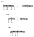
- a simplification of the production can be according to FIG. 4 indicated embodiment achieved in that the flame barrier sections 4 - as is known per se - is formed by a common spiral winding of a respective corrugated and a smooth metal strip.
- the concentric section 5 can be carried out in a simple manner by further winding the smooth metal strip, which thus wound tightly sealed without passage gaps forms a quasi-massive concentric section 5 in the form of a cooling ring.
- the housing 1 forms a containment cage for a disk-shaped flame arrester, such as they are suitable for smaller device dimensions. Similar to the embodiment according to FIG. 1 two annular flame trap sections 4 are radially separated from each other by a concentric section 5 in the form of a ring. In addition, however, another concentric portion 11 is provided in the form of a central core, around which the radially inner flame trap is annular.
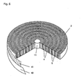
- FIG. 6 shows an embodiment of a spiral winding of a flame arrester, which is formed from a common winding of a corrugated metal strip 41 with a smooth metal strip 42.
- a plurality, here five annular concentric portions 5 are formed, which are produced in that in the areas of the concentric portions 5, the smooth metal strip 42 alone, that is, without corrugated metal strip 41, has been wound.
- each flame barrier sections 4 form with für spalten whose surfaces are limited, so that an excessive heating of the flame barrier sections 4 can be safely avoided.
Landscapes
- Public Health (AREA)
- Business, Economics & Management (AREA)
- Emergency Management (AREA)
- Health & Medical Sciences (AREA)
- Gas Burners (AREA)
- Fireproofing Substances (AREA)
- Insulated Conductors (AREA)
- Building Environments (AREA)
- Fire-Extinguishing By Fire Departments, And Fire-Extinguishing Equipment And Control Thereof (AREA)
- Gas Separation By Absorption (AREA)
- Iron Core Of Rotating Electric Machines (AREA)
- Rigid Pipes And Flexible Pipes (AREA)
- Exhaust Gas After Treatment (AREA)
- Installation Of Indoor Wiring (AREA)
- Sink And Installation For Waste Water (AREA)
- Sealing Material Composition (AREA)
- Furnace Housings, Linings, Walls, And Ceilings (AREA)
- Gasket Seals (AREA)
- Heat-Exchange Devices With Radiators And Conduit Assemblies (AREA)
Description
- Die Erfindung betrifft eine dauerbrandsichere Flammensperre mit einem eine Leitung abschließenden Durchströmquerschnitt, in dem sich ein Flammensperreinsatz mit einer Flammensperranordnung befindet, die eine Vielzahl von die Dauerbrandsicherheit sicherstellenden Durchtrittsspalten aufweist, die durch einen gemeinsam mit einem glatten Metallstreifen gewickelten gewellten Metallstreifen gebildet sind.
- Dauerbrandsichere Flammensperren dieser Art dienen der Entlüftung explosionsgefährdeter Anlagen. Sie müssen bei einer Entzündung der ausströmenden Gas- bzw. Produktdampf-Luft-Gemische dauerbrandsicher ausgelegt sein, also ein Abfackeln der Gemische über einen unbegrenzten Zeitraum ermöglichen, ohne dass es zu einem Flammendurchschlag in das zu schützende Anlagenteil kommen kann. Eine-dauerbrandsichere Flammensperre dieser Art ist beispielsweise durch
DE 1 041 423 bekannt. Der Durchströmquerschnitt ist dabei ringförmig ausgebildet und umschließt ein hohles Kernstück, durch das Umgebungsluft strömt, die durch die Flamme beim Abfackeln des Gases oder Dampfs aus der Umgebung angesaugt wird und zur Kühlung eines als Flammensperre dienenden Ringrostes dient. Es hat sich herausgestellt, dass bei einer scheibenförmigen Flammensperre oder bei einer ringförmigen Flammensperre die freie Fläche der zum Durchtritt des Gases dienenden Flammensperre nicht zu groß sein darf, um eine unzulässige hohe Aufheizung im Zentrum der Flammensperre zu vermeiden, die zu einem Flammendurchschlag führen könnte. Daher können scheibenförmige Flammensperren nur bis zu einem bestimmten maximalen Durchmesser eingesetzt werden und dürfen ringförmige Flammensperren eine bestimmte Breite des Rings nicht überschreiten. Daher kommt es bei der Dimensionierung der Flammensperre in vielen Fällen zu Schwierigkeiten, da die Flammensperre jeweils der Anschlussweite der Leitung anzupassen ist und bei Gemischen mit großen Zünddurchschlagsvermögen (Explosionsgruppe IIB bzw. IIC), bei denen sehr enge flammenlöschende Spalte in der Flammensperre notwendig sind, die Breite bzw. der innere und/oder äußere Durchmesser der Flammensperre so zu dimensionierten ist, dass eine gewünschte Durchströmmenge erzielt wird. -
US 5,336,083 offenbart eine Detonationssperranordnung, die mehrteilig aufgebaut ist. In Strömungsrichtung gesehen besteht sie aus einem flammenlöschenden Material, das eine Vielzahl von die Flammenlöschung bewirkenden Durchtrittsspalten aufweist. Dieses Material wird durch geeignete Schüttmaterialien gebildet. In Strömungsrichtung beiderseits des flammenlöschenden Materials befinden sich Detonationsbremsen in Form von aufeinander gestapelten Platten, die schlitzförmige Zwischenräume aufweisen, durch die die Flammenfront hindurchtreten muss, um zu dem flammenlöschenden Material in der Mitte zu gelangen. In einer Variante der Detonationsbremsen bestehen diese nicht aus geradlinigen Platten, sondern aus spirelförmig aufgewickelten Bändern, wobei die zum Gastritt benötigten schlitzförmigen Zwischenräume durch ein zwischengelegtes gewelltes Band als Abstandshalter sichergestellt werden. Die Detonantionsbremsen haben die Funktion, die Detonationsfront abzufangen und in Einzel-Detonationsfronten aufzuteilen. Die offenbarte Detonationssperranordnung ist nicht dauerbrandsicher sondern dazu ausgelegt, nur für eine zeitlich begrenzte Brandsicherheit zu sorgen. Diese Funktion übernimmt das mittig angeordnete Schüttmaterial mit den flammenlöschenden feinen Spalten, das über den gesamten Durchströmquerschnitt gleichmäßig verteilt ist. -
FR 1 466 440 AT 250 544 - Der Erfindung liegt die Aufgabe zugrunde, eine dauerbrandsichere Flammensperre in Form einer scheibenförmigen oder ringförmigen Flammensperre anzugeben, mit der eine die Dauerbrandsicherheit gefährdende Aufheizung der Flammensperre in einfacher Weise vermieden werden kann.
- Zur Lösung dieser Aufgabe ist erfindungsgemäß eine dauerbrandsichere Flammensperre der eingangs erwähnten Art dadurch gekennzeichnet, dass innerhalb des Durchströmquerschnitts wenigstens zwei Flammensperranordnungen mit den Durchtrittsspalten angeordnet sind, zwischen denen sich ein einen Kühlring bildender konzentrischer Abschnitt befindet, der massiv ohne Durchtrittsspalte ausgebildet ist.
- Der konzentrische Abschnitt kann als ringförmiger Abschnitt ausgebildet sein und somit den Durchströmquerschnitt in mehrere ringförmige Durchströmflächen unterteilen. Ergänzend dazu kann ein zentrisch angeordneter Kern vorgesehen sein.
- Zweckmäßigerweise ist die mit den Durchtrittsspalten ausgebildete Querschnittsfläche des Flammensperreinsatzes größer als die Querschnittsfläche ohne Durchtrittsspalte. In einer bevorzugten Ausführungsform der Erfindung beträgt die Fläche ohne Durchtrittsspalte zwischen 35 und 40 % der Gesamtfläche einer Ringflammensperre und zwischen 25 und 35 % der Querschnittsfläche einer Scheiben-Flammensperre.
- Der erfindungsgemäß vorgesehene wenigstens eine konzentrische Abschnitt unterteilt somit die Fläche der scheibenförmigen Flammensperre, wodurch eine unzulässige Aufheizung im radialen Innenbereich der Flammensperre vermieden wird. Hierzu kann der wenigstens eine konzentrische Abschnitt aus einem wärmeisolierenden Material gebildet sein, um den Bereich, in dem sich eine Flamme auf der Fläche der Flammensperre ausbildet, zu begrenzen und eine Aufheizung in diesem Bereich zu verringern. Es ist aber auch möglich und in vielen Fällen bevorzugt, den konzentrischen Abschnitt aus einem gut Wärme leitenden Material auszubilden, um im konzentrischen Bereich eine verbesserte Wärmeabfuhr innerhalb des Durchströmquerschnitts der Flammensperre zu bewerkstelligen. So kann beispielsweise ein zentrisch angeordneter Kern als konzentrischer Abschnitt, der aus gut Wärme leitenden Material gebildet ist, eine verbesserte Wärmeableitung im Zentrum des Durchströmquerschnits bewirken und beispielsweise eine scheibenförmige Flammensperre zu einer Flammensperre werden lassen, deren Durchtrittsspalte auf einer ringförmigen Fläche angeordnet sind.
- In einer besonders bevorzugten Ausführungsform der Erfindung kann der konzentrische Abschnitt aus einem spiralförmig dicht an dicht gewickelten glatten Metallstreifen gebildet sein. Dies ist besonders vorteilhaft, wenn die Durchtrittsspalte des Durchströmquerschnitts in an sich bekannter Weise durch einen gemeinsam mit einem glatten Metallstreifen spiralförmig gewickelten gewellten Metallstreifen gebildet sind. Unter Beibehaltung des Wickelvorganges kann zur Bildung eines erfindungsgemäßen konzentrischen Abschnittes die Zufuhr des gewellten Metallstreifens zu der Wickelvorrichtung gestoppt und nur noch der glatte Metallstreifen gewickelt werden, bis regelmäßig nach einer gewissen Dicke des so entstandenen konzentrischen Abschnitts der gewellte Metallstreifen wieder mit dem glatten Metallstreifen zugeführt wird, um einen äußeren ringförmigen Abschnitt um den konzentrischen Abschnitt herum zu bilden.
- Die Erfindung soll im Folgenden anhand von in der Zeichnung dargestellten Ausführungsbeispielen näher erläutert werden. Es zeigen:
- Figur 1
- einen Schnitt durch ein erstes Ausführungsbeispiel einer ringförmigen Flammensperre
- Figur 2
- die Flammensperre gemäß
Figur 1 als Teil einer Armatur - Figur 3
- einen Schnitt gemäß
Figur 1 durch ein zweites Ausführungsbeispiel einer erfindungsgemäßen Flammensperre - Figur 4
- eine Flammensperre gemäß
Figur 1 mit einem gewickelten konzentrischen Abschnitt - Figur 5
- einen Schnitt durch eine gemäß einem weiteren Ausführungsbeispiel der Erfindung ausgebildeten scheibenförmigen Flammensperre
- Figur 6
- eine perspektivische schematische, teilweise weg gebrochene Darstellung einer weiteren Ausführungsform der Erfindung, bei der innerhalb einer spiralförmigen Wicklung der Flammensperre mehrere konzentrische Abschnitt 5 vorgesehen sind.
-
Figur 1 zeigt ein erstes Ausführungsbeispiel einer erfindungsgemäßen Flammensperre, die ringförmig ausgebildet ist. Demgemäß ist ein Gehäuse 1 vorgesehen, das einen ringförmigen Umfassungskäfig für einen ringförmigen Durchströmquerschnitt 2 bildet. Ein Mittelteil 3 wird durch das Gehäuse 1 frei gelassen. - In den Durchströmquerschnitt 2 sind zwei ringförmige Flammensperranordnungen 4 angeordnet, die radial durch einen konzentrischen Abschnitt 5 voneinander getrennt sind. Die Flammensperranordnungen 4 weisen Durchtrittsspalte auf, während der konzentrische Abschnitt 5 ohne Durchtrittsspalte ausgebildet ist und aus einem gut Wärme leitenden Material, insbesondere Metall, besteht.
- Die Flammensperranordnungen 4 bilden zusammen mit dem konzentrischen Abschnitt 5 einen Flammensperreinsatz 4, 5 mit einer Breite B. Die radiale Breite B2 des einen Kühlring bildenden konzentrischen Abschnitts 5 ist etwa gleich groß wie die gleich groß ausgebildeten Breiten B1 der Flammensperranordnungen 4.
-
Figur 2 zeigt eine Armatur 6, die mit der Flammensperre gemäßFigur 1 ausgestattet ist. Die Armatur 6 weist einen Anschlussflansch 7 für eine von einem Behälter kommende Leitung oder einen entsprechenden Anschlussflansch eines Behälters auf. Aus dem Behälter ausströmendes Gas (worunter auch Produktdämpfe verstanden werden) strömt in Richtung der inFigur 2 dargestellten Strömungspfeile 8. Die Armatur 6 weist ein sich trichterförmig erweiterndes Gehäuse 9 auf, das von dem Gehäuse 1 der Flammensperre abgeschlossen wird. Das Gas durchströmt die Flammensperrabschnitte 4 und kann nach dem Durchtritt durch die Flammensperre durch Entzündung zu einer Flamme 10 verbrannt und damit unschädlich gemacht werden. Der ringförmige konzentrische Abschnitt 5 bewirkt eine Begrenzung der ringförmigen Flächen der Flammensperrabschnitte 4 und bewirkt aufgrund seiner massiven Ausbildung ohne Durchtrittsspalte eine gute Wärmeableitung, also eine Kühlung der Flammensperrabschnitte 4. Dadurch wird verhindert, dass die Flammensperrabschnitte 4 sich auf der zum Gehäuse 9 der Armatur 6 zeigenden Seite soweit aufheizen, dass die Entzündungstemperatur für das ausströmende Gas erreicht wird. - Bei der in
Figur 3 dargestellten zweiten Ausführungsform sind konzentrisch zueinander drei Flammensperrabschnitte 4 angeordnet, die durch zwei konzentrische Abschnitte 5 in Ringform radial voneinander getrennt sind. Auf diese Weise lässt sich eine Flammensperre mit einem größeren Durchströmquerschnitt realisieren, ohne die Gefahr einer zu großen Aufheizung der Flammensperrabschnitte 4 eingehen zu müssen. - Die in den
Figuren 1 bis 3 dargestellten konzentrischen Abschnitte 5 können aus massiven Metall gebildet sein, um eine gute Wärmeableitung zu bewirken. Dabei muss jedoch sichergestellt werden, dass am Übergang zwischen den Flammensperrabschnitten 4 und den konzentrischen Abschnitten 5 keine zu großen Spaltweiten entstehen. - Eine Vereinfachung der Fertigung lässt sich gemäß den
Figur 4 angedeuteten Ausführungsbeispiel dadurch erzielen, dass die Flammensperrabschnitte 4 - wie an sich bekannt - durch ein gemeinsames spiralförmiges Aufwickeln von jeweils einem gewellten und einem glatten Metallband gebildet wird. Der konzentrische Abschnitt 5 kann in einfacher Weise durch Weiterwickeln des glatten Metallbandes erfolgen, das somit dicht an dicht ohne Durchtrittsspalte gewickelt einen quasi massive konzentrischen Abschnitt 5 in Form eines Kühlringes ausbildet. - Bei dem in
Figur 5 dargestellten Ausführungsbeispiel bildet das Gehäuse 1' einen Umfassungskäfig für eine scheibenförmige Flammensperre, wie sie für kleinere Geräteabmessungen verwendbar sind. Ähnlich wie in der Ausführungsform gemäßFigur 1 werden zwei ringförmige Flammensperrabschnitte 4 durch einen konzentrischen Abschnitt 5 in Form eines Ringes radial voneinander getrennt. Zusätzlich ist jedoch ein weiterer konzentrischer Abschnitt 11 in Form eines zentrischen Kerns vorgesehen, um den herum der radial innere Flammensperrabschnitt ringförmig ausgebildet ist. - Die insbesondere zum Querschnittszentrum hin kritische Aufheizung einer scheibenförmigen Flammensperre wird somit einerseits durch den ringförmigen konzentrischen Abschnitt 5 ("Kühlring") und andererseits durch den im Zentrum angeordneten konzentrischen Abschnitt 11 ("Kühlkern") verhindert.
-
Figur 6 zeigt ein Ausführungsbeispiel einer spiralförmigen Wicklung einer Flammensperre, die aus einer gemeinsamen Aufwicklung eines gewellten Metallbandes 41 mit einem glatten Metallband 42 gebildet ist. Innerhalb der kreisförmigen Fläche des Durchströmquerschnitts 2 sind mehrere, hier fünf ringförmige konzentrische Abschnitte 5 ausgebildet, die dadurch hergestellt sind, dass in den Bereichen der konzentrischen Abschnitte 5 das glatte Metallband 42 allein, d.h. ohne dass gewellte Metallband 41, aufgewickelt worden ist. - Im Zentrum des Durchströmquerschnitts 2 befindet sich ein konzentrischer Abschnitt 11 in Form eines zentrischen Kerns, der vorzugsweise ein massiver Einsatz aus einem gut Wärme leitenden Material ist. Somit bilden sich im Durchströmquerschnitt benachbart zu den konzentrischen ringförmigen Abschnitten 5 jeweils Flammensperrabschnitte 4 mit Durchströmspalten aus, deren Flächen begrenzt sind, sodass eine zu große Aufheizung der Flammensperrabschnitte 4 sicher vermieden werden kann.
Claims (8)
- Dauerbrandsichere Flammensperre mit einem eine Leitung abschließenden Durchströmquerschnitt (2), in dem sich ein Flammensperreinsatz (4, 5) mit einer Flammensperranordnung (4) befindet, die eine Vielzahl von die Dauerbrandsicherheit sicherstellenden Durchtrittsspalten aufweist, die durch einen gemeinsam mit einem glatten Metallstreifen (42) gewickelten gewellten Metallstreifen (41) gebildet sind, dadurch gekennzeichnet, dass innerhalb des Durchströmquerschnitts (2) wenigstens zwei Flammensperranordnungen (4) mit den Durchtrittsspalten angeordnet sind, zwischen denen sich ein einen Kühlring bildender konzentrischer Abschnitt (5) befindet, der massiv ohne Durchtrittsspalte ausgebildet ist.
- Dauerbrandsichere Flammensperre nach Anspruch 1, dadurch gekennzeichnet, dass die mit den Durchtrittsspalten ausgebildete Querschnittsfläche des Flammensperreinsatzes (4, 5) größer als die Querschnittsfläche ohne Durchtrittsspalte ist.
- Dauerbrandsichere Flammensperre nach Anspruch 1 oder 2, dadurch gekennzeichnet, dass ein zentrisch angeordneter Kern als konzentrischer Abschnitt (11) vorgesehen ist.
- Dauerbrandsichere Flammensperre nach einem der Ansprüche 1 bis 3, dadurch gekennzeichnet, dass der konzentrische Abschnitt (5, 11) aus einem gut Wärme leitenden Material gebildet ist.
- Dauerbrandsichere Flammensperrech nach einem der Ansprüche 1 bis 4, dadurch gekennzeichnet, dass innerhalb des Durchströmquerschnitts (2) mehrere ringförmige Abschnitte als konzentrische Abschnitte (5) vorgesehen sind, an die sich in radialer Richtung jeweils Flammensperranordnungen (4) mit Durchtrittsspalten anschließen.
- Dauerbrandsichere Flammensperre nach einem der Ansprüche 1 bis 5, dadurch gekennzeichnet, dass der konzentrische Abschnitt (5, 11) aus einem spiralförmig dicht an dicht gewickelten glatten Metallstreifen (42) gebildet ist.
- Dauerbrandsichere Flammensperre nach Anspruch 6, dadurch gekennzeichnet, dass die Durchtrittsspalte des Durchströmquerschnitts (2) durch einen gemeinsam mit einem glatten Metallstreifen (42) spiralförmig gewickelten gewellten Metallstreifen (41) gebildet sind.
- Dauerbrandsichere Flammensperre nach einem der Ansprüche 1 bis 7, dadurch gekennzeichnet, dass der Durchströmquerschnitt (2) eine Ringform aufweist.
Priority Applications (3)
| Application Number | Priority Date | Filing Date | Title |
|---|---|---|---|
| PL04738609T PL1631358T3 (pl) | 2003-06-06 | 2004-06-03 | Trwała ognioodporna zapora płomieni |
| SI200431237T SI1631358T1 (sl) | 2003-06-06 | 2004-06-03 | Trajna ognjevarna plamenska zapora |
| CY20091101146T CY1109571T1 (el) | 2003-06-06 | 2009-11-05 | Ανθεκτικη σε συνεχη καυση φλογοπαγιδα |
Applications Claiming Priority (2)
| Application Number | Priority Date | Filing Date | Title |
|---|---|---|---|
| DE10326150A DE10326150B4 (de) | 2003-06-06 | 2003-06-06 | Dauerbrandsichere Flammensperre |
| PCT/DE2004/001155 WO2004108219A1 (de) | 2003-06-06 | 2004-06-03 | Dauerbrandsichere flammensperre |
Publications (2)
| Publication Number | Publication Date |
|---|---|
| EP1631358A1 EP1631358A1 (de) | 2006-03-08 |
| EP1631358B1 true EP1631358B1 (de) | 2009-09-02 |
Family
ID=33494929
Family Applications (1)
| Application Number | Title | Priority Date | Filing Date |
|---|---|---|---|
| EP04738609A Expired - Lifetime EP1631358B1 (de) | 2003-06-06 | 2004-06-03 | Dauerbrandsichere flammensperre |
Country Status (17)
| Country | Link |
|---|---|
| US (1) | US7918664B2 (de) |
| EP (1) | EP1631358B1 (de) |
| JP (1) | JP4226628B2 (de) |
| KR (1) | KR100904126B1 (de) |
| AT (1) | ATE441463T1 (de) |
| BR (1) | BRPI0411014A (de) |
| CA (1) | CA2526788C (de) |
| CY (1) | CY1109571T1 (de) |
| DE (2) | DE10326150B4 (de) |
| DK (1) | DK1631358T3 (de) |
| ES (1) | ES2329372T3 (de) |
| NO (1) | NO20055065L (de) |
| PL (1) | PL1631358T3 (de) |
| PT (1) | PT1631358E (de) |
| SI (1) | SI1631358T1 (de) |
| TW (1) | TWI325481B (de) |
| WO (1) | WO2004108219A1 (de) |
Cited By (1)
| Publication number | Priority date | Publication date | Assignee | Title |
|---|---|---|---|---|
| EP4350916A1 (de) | 2022-10-05 | 2024-04-10 | ALSTOM Holdings | Flammendichte kabeldurchführung, container und schienenfahrzeug mit einer flammendichten kabeldurchführung, sowie verwendung einer schaumstoffdichtung |
Families Citing this family (24)
| Publication number | Priority date | Publication date | Assignee | Title |
|---|---|---|---|---|
| DK200701284A (da) * | 2007-09-07 | 2009-03-08 | Hansen Lars | Fakkel med betjenings-anordning |
| US9512998B2 (en) * | 2008-02-28 | 2016-12-06 | Lamplight Farms Incorporated | Twin wick torch |
| US8550813B2 (en) | 2008-02-28 | 2013-10-08 | Lamplight Farms Incorporated | No touch pour torch top |
| US8435029B2 (en) * | 2008-02-28 | 2013-05-07 | Lamplight Farms Incorporated | Touchless fill large flame torch |
| US20100112503A1 (en) * | 2008-10-13 | 2010-05-06 | Daniel Masterson | Large flame torch with textured flame bowl |
| KR101008402B1 (ko) * | 2008-12-19 | 2011-01-14 | 삼성에스디아이 주식회사 | 개질장치 |
| CH701405A1 (de) * | 2009-07-03 | 2011-01-14 | Johannes Schwarz | Brandhemmender Körper und Band zur Herstellung desselben. |
| DE102010016782B4 (de) * | 2010-05-04 | 2016-12-08 | R.Stahl Schaltgeräte GmbH | Druckentlastungsvorrichtung für druckfest gekapselte Gehäuse |
| DE102010056590A1 (de) * | 2010-12-30 | 2012-07-05 | Leinemann Gmbh & Co. Kg | Flammendurchschlagsicherung |
| US20120189966A1 (en) * | 2011-01-21 | 2012-07-26 | Brooker Dwight E | Detonation flame arrestor including a transition point/attenuation matrix and torturous path media |
| USD670415S1 (en) | 2011-01-24 | 2012-11-06 | Lamplight Farms Incorporated | Twin wick top for a torch |
| US9702549B2 (en) | 2012-05-29 | 2017-07-11 | Lamplight Farms Incorporated | Torch with twist open fire bowl |
| DE102013208081A1 (de) * | 2013-05-02 | 2014-11-06 | Robert Bosch Gmbh | Fluidverteiler, Elektrolyseur sowie Verfahren zur Funktion eines Fluidverteilers |
| USD733199S1 (en) | 2013-12-09 | 2015-06-30 | Lamplight Farms Incorporated | Liquid fuel torch burner with indented top |
| US9612010B1 (en) | 2013-12-09 | 2017-04-04 | Lamplight Farms Incorporated | Enhanced torch top burner |
| GB2522476A (en) * | 2014-01-28 | 2015-07-29 | Elmac Technologies Ltd | Flame arrester |
| BR112016017471A2 (pt) | 2014-01-28 | 2018-05-15 | Elmac Tech Limited | corta-chamas |
| CN105334305B (zh) * | 2014-07-14 | 2020-10-16 | 霍尼韦尔国际公司 | 多孔构件 |
| US9987508B2 (en) * | 2016-08-31 | 2018-06-05 | Emerson Process Management Regulator Technologies Tulsa, Llc | Hybrid composite flame cell |
| US20180056100A1 (en) | 2016-08-31 | 2018-03-01 | Emerson Process Management Regulator Technologies Tulsa, Llc | Method for Manufacturing a Flame Arrestor |
| KR102002521B1 (ko) * | 2017-12-28 | 2019-10-01 | 주식회사 탑세이프 | 화염 차단 장치 |
| KR102002522B1 (ko) * | 2017-12-28 | 2019-07-22 | 주식회사 탑세이프 | 화염 차단 장치 |
| GB201816489D0 (en) | 2018-10-10 | 2018-11-28 | Elmac Tech Limited | Flame Arrester Element |
| CN111097118B (zh) * | 2019-12-19 | 2020-11-27 | 山东双枭机电科技有限公司 | 流量分散型低压降大口径阻火器 |
Family Cites Families (17)
| Publication number | Priority date | Publication date | Assignee | Title |
|---|---|---|---|---|
| US2420599A (en) * | 1944-02-04 | 1947-05-13 | Shand And Jurs Company | Flame arrester |
| DE922756C (de) * | 1952-06-19 | 1955-01-24 | Wilke Werke Ag | Sicherung zum Aufhalten von Flammen und Explosionen |
| DE1041423B (de) * | 1957-04-04 | 1958-10-16 | Leinemann Co Flammenfilter | Explosionssichere Lueftungsvorrichtung fuer Behaelter zur Lagerung und zum Transport von feuergefaehrlichen Fluessigkeiten und Gasen |
| US3227241A (en) * | 1964-03-16 | 1966-01-04 | Corning Glass Works | Ceramic mufflers |
| AT250544B (de) * | 1964-06-17 | 1966-11-10 | Johann Ing Auer | Rückschlagsicherung gegen den Durchtritt von Flammen in Leitungen für brennbare Flüssigkeiten oder Gase, insbesondere flüssige oder gasförmige Brenn- oder Treibstoffe |
| US3748111A (en) * | 1971-06-11 | 1973-07-24 | W Klose | Flame arrestor |
| GB2019718B (en) * | 1977-12-09 | 1982-08-04 | Chalmers & Mitchell Ltd | Enclosures for electrical equipment |
| JPS59163724U (ja) * | 1983-04-15 | 1984-11-02 | 金子産業株式会社 | フレ−ムアレスタ |
| US4909730A (en) * | 1989-01-23 | 1990-03-20 | Westech Industrial Ltd. | Flame arrester having detonation-attenuating means |
| US5336083A (en) * | 1991-02-22 | 1994-08-09 | Rajewski Robert K | Detonation arrestor with cooling section and quenching section |
| SG49198A1 (en) * | 1992-06-30 | 1998-05-18 | Chem Mech Engineering | Flame arrestor apparatus |
| JPH0814509A (ja) | 1994-07-01 | 1996-01-19 | Paloma Ind Ltd | パルス燃焼器 |
| US5752812A (en) * | 1996-02-28 | 1998-05-19 | Delaware Capital Formation, Inc. | Vapor recovery pump |
| DE19818572C1 (de) * | 1998-04-25 | 1999-11-11 | Leinemann Gmbh & Co | Verfahren zum Unschädlichmachen einer Detonationsfront und Detonationssicherung |
| US6179608B1 (en) * | 1999-05-28 | 2001-01-30 | Precision Combustion, Inc. | Swirling flashback arrestor |
| US6338319B1 (en) * | 1999-11-12 | 2002-01-15 | Water Heater Industry Joint Research & Development | Water heater with flammable vapor flame arrestor and method of operation |
| DE10336530B3 (de) * | 2003-08-05 | 2005-02-17 | Leinemann Gmbh & Co. | Flammendurchschlagsicherung |
-
2003
- 2003-06-06 DE DE10326150A patent/DE10326150B4/de not_active Expired - Fee Related
-
2004
- 2004-05-31 TW TW093115494A patent/TWI325481B/zh not_active IP Right Cessation
- 2004-06-03 WO PCT/DE2004/001155 patent/WO2004108219A1/de not_active Ceased
- 2004-06-03 DE DE502004010006T patent/DE502004010006D1/de not_active Expired - Lifetime
- 2004-06-03 US US10/559,761 patent/US7918664B2/en not_active Expired - Fee Related
- 2004-06-03 EP EP04738609A patent/EP1631358B1/de not_active Expired - Lifetime
- 2004-06-03 DK DK04738609T patent/DK1631358T3/da active
- 2004-06-03 CA CA2526788A patent/CA2526788C/en not_active Expired - Fee Related
- 2004-06-03 JP JP2006508120A patent/JP4226628B2/ja not_active Expired - Fee Related
- 2004-06-03 ES ES04738609T patent/ES2329372T3/es not_active Expired - Lifetime
- 2004-06-03 KR KR1020057023459A patent/KR100904126B1/ko not_active Expired - Fee Related
- 2004-06-03 PT PT04738609T patent/PT1631358E/pt unknown
- 2004-06-03 SI SI200431237T patent/SI1631358T1/sl unknown
- 2004-06-03 AT AT04738609T patent/ATE441463T1/de active
- 2004-06-03 PL PL04738609T patent/PL1631358T3/pl unknown
- 2004-06-03 BR BRPI0411014-5A patent/BRPI0411014A/pt not_active IP Right Cessation
-
2005
- 2005-10-31 NO NO20055065A patent/NO20055065L/no not_active Application Discontinuation
-
2009
- 2009-11-05 CY CY20091101146T patent/CY1109571T1/el unknown
Cited By (2)
| Publication number | Priority date | Publication date | Assignee | Title |
|---|---|---|---|---|
| EP4350916A1 (de) | 2022-10-05 | 2024-04-10 | ALSTOM Holdings | Flammendichte kabeldurchführung, container und schienenfahrzeug mit einer flammendichten kabeldurchführung, sowie verwendung einer schaumstoffdichtung |
| WO2024074463A1 (de) | 2022-10-05 | 2024-04-11 | Alstom Holdings | Flammendichte kabeldurchführung, container und schienenfahrzeug mit einer flammendichten kabeldurchführung, sowie verwendung einer schaumstoffdichtung |
Also Published As
| Publication number | Publication date |
|---|---|
| JP2006526754A (ja) | 2006-11-24 |
| CY1109571T1 (el) | 2014-08-13 |
| KR20060009386A (ko) | 2006-01-31 |
| ES2329372T3 (es) | 2009-11-25 |
| DK1631358T3 (da) | 2009-11-23 |
| US7918664B2 (en) | 2011-04-05 |
| PT1631358E (pt) | 2009-09-29 |
| EP1631358A1 (de) | 2006-03-08 |
| US20060144599A1 (en) | 2006-07-06 |
| JP4226628B2 (ja) | 2009-02-18 |
| KR100904126B1 (ko) | 2009-06-24 |
| PL1631358T3 (pl) | 2010-02-26 |
| DE10326150A1 (de) | 2005-02-17 |
| NO20055065L (no) | 2005-10-31 |
| SI1631358T1 (sl) | 2009-12-31 |
| ATE441463T1 (de) | 2009-09-15 |
| CA2526788C (en) | 2011-11-01 |
| TW200506277A (en) | 2005-02-16 |
| WO2004108219A1 (de) | 2004-12-16 |
| DE10326150B4 (de) | 2005-12-15 |
| BRPI0411014A (pt) | 2006-07-04 |
| CA2526788A1 (en) | 2004-12-16 |
| DE502004010006D1 (de) | 2009-10-15 |
| TWI325481B (en) | 2010-06-01 |
Similar Documents
| Publication | Publication Date | Title |
|---|---|---|
| EP1631358B1 (de) | Dauerbrandsichere flammensperre | |
| EP1528948B1 (de) | Flammendurchschlagsicherung | |
| EP2260906B1 (de) | Flammensperranordnung | |
| EP2842609B1 (de) | Druckentlastungsvorrichtung für druckfest gekapselte Gehäuse mit einem porösen Körper mit Übermaßpassung | |
| DE69305351T3 (de) | Flammen- und explosionsschutzsicherung | |
| EP1240923B1 (de) | Flammensperrbauteil | |
| DE2020062B2 (de) | Flammenschranke zum verhindern des flammenaustritts aus explosions-entlastungsventilen | |
| CH654440A5 (de) | Ueberspannungsableiter. | |
| DE2337743C3 (de) | Funkenstrecke | |
| EP2658612B1 (de) | Flammendurchschlagsicherung | |
| DE20321089U1 (de) | Dauerbrandsichere Flammensperre | |
| DE2162269C3 (de) | Strombegrenzungsvorrichtung | |
| DE102018116576B3 (de) | Flammen-Sperreinheit sowie Verfahren zu ihrer Herstellung | |
| DE19506057B4 (de) | Löschfunkenstreckenanordnung | |
| AT504898B1 (de) | Flammfilter | |
| AT507409B1 (de) | Flammfilter | |
| EP2332617A1 (de) | Flammensperre für Absauganlagen | |
| EP0668463B1 (de) | Abstandhalter | |
| EP3149814B1 (de) | Überspannungsableiter | |
| EP0048424B1 (de) | Elektrische Überstromsicherung | |
| DE661801C (de) | Trockene Gasrueckschlagsicherung | |
| EP3127199B1 (de) | Überspannungsableiter | |
| DE1152715B (de) | Waermeaustauscher mit jeweils einen Stroemungskanal begrenzenden, radial durch Stirnleisten im Abstand gehaltenen Blechen | |
| DE3873796T2 (de) | Flammenrueckschlagsicherung und verfahren zu deren herstellung. | |
| DE2850618A1 (de) | Entlueftung fuer flugzeugtanks |
Legal Events
| Date | Code | Title | Description |
|---|---|---|---|
| PUAI | Public reference made under article 153(3) epc to a published international application that has entered the european phase |
Free format text: ORIGINAL CODE: 0009012 |
|
| 17P | Request for examination filed |
Effective date: 20051102 |
|
| AK | Designated contracting states |
Kind code of ref document: A1 Designated state(s): AT BE BG CH CY CZ DE DK EE ES FI FR GB GR HU IE IT LI LU MC NL PL PT RO SE SI SK TR |
|
| GBC | Gb: translation of claims filed (gb section 78(7)/1977) | ||
| DAX | Request for extension of the european patent (deleted) | ||
| 17Q | First examination report despatched |
Effective date: 20060609 |
|
| EL | Fr: translation of claims filed | ||
| GRAP | Despatch of communication of intention to grant a patent |
Free format text: ORIGINAL CODE: EPIDOSNIGR1 |
|
| GRAS | Grant fee paid |
Free format text: ORIGINAL CODE: EPIDOSNIGR3 |
|
| GRAA | (expected) grant |
Free format text: ORIGINAL CODE: 0009210 |
|
| AK | Designated contracting states |
Kind code of ref document: B1 Designated state(s): AT BE BG CH CY CZ DE DK EE ES FI FR GB GR HU IE IT LI LU MC NL PL PT RO SE SI SK TR |
|
| REG | Reference to a national code |
Ref country code: CH Ref legal event code: NV Representative=s name: BRAUNPAT BRAUN EDER AG Ref country code: CH Ref legal event code: EP |
|
| REG | Reference to a national code |
Ref country code: PT Ref legal event code: SC4A Free format text: AVAILABILITY OF NATIONAL TRANSLATION Effective date: 20090923 |
|
| REG | Reference to a national code |
Ref country code: IE Ref legal event code: FG4D Free format text: LANGUAGE OF EP DOCUMENT: GERMAN |
|
| REF | Corresponds to: |
Ref document number: 502004010006 Country of ref document: DE Date of ref document: 20091015 Kind code of ref document: P |
|
| REG | Reference to a national code |
Ref country code: SE Ref legal event code: TRGR |
|
| REG | Reference to a national code |
Ref country code: DK Ref legal event code: T3 |
|
| REG | Reference to a national code |
Ref country code: RO Ref legal event code: EPE Ref country code: ES Ref legal event code: FG2A Ref document number: 2329372 Country of ref document: ES Kind code of ref document: T3 |
|
| REG | Reference to a national code |
Ref country code: GR Ref legal event code: EP Ref document number: 20090402815 Country of ref document: GR |
|
| REG | Reference to a national code |
Ref country code: EE Ref legal event code: FG4A Ref document number: E003789 Country of ref document: EE Effective date: 20091130 |
|
| REG | Reference to a national code |
Ref country code: PL Ref legal event code: T3 |
|
| REG | Reference to a national code |
Ref country code: SK Ref legal event code: T3 Ref document number: E 6351 Country of ref document: SK |
|
| REG | Reference to a national code |
Ref country code: HU Ref legal event code: AG4A Ref document number: E007133 Country of ref document: HU |
|
| PLBE | No opposition filed within time limit |
Free format text: ORIGINAL CODE: 0009261 |
|
| STAA | Information on the status of an ep patent application or granted ep patent |
Free format text: STATUS: NO OPPOSITION FILED WITHIN TIME LIMIT |
|
| 26N | No opposition filed |
Effective date: 20100603 |
|
| PGFP | Annual fee paid to national office [announced via postgrant information from national office to epo] |
Ref country code: CH Payment date: 20110623 Year of fee payment: 8 Ref country code: MC Payment date: 20110621 Year of fee payment: 8 Ref country code: IE Payment date: 20110621 Year of fee payment: 8 Ref country code: PT Payment date: 20110525 Year of fee payment: 8 Ref country code: SE Payment date: 20110622 Year of fee payment: 8 Ref country code: GR Payment date: 20110627 Year of fee payment: 8 Ref country code: LU Payment date: 20110622 Year of fee payment: 8 |
|
| PGFP | Annual fee paid to national office [announced via postgrant information from national office to epo] |
Ref country code: BG Payment date: 20110622 Year of fee payment: 8 Ref country code: EE Payment date: 20110627 Year of fee payment: 8 Ref country code: FI Payment date: 20110620 Year of fee payment: 8 Ref country code: SI Payment date: 20110524 Year of fee payment: 8 Ref country code: RO Payment date: 20110530 Year of fee payment: 8 Ref country code: SK Payment date: 20110527 Year of fee payment: 8 |
|
| PGFP | Annual fee paid to national office [announced via postgrant information from national office to epo] |
Ref country code: CY Payment date: 20110504 Year of fee payment: 8 |
|
| PGFP | Annual fee paid to national office [announced via postgrant information from national office to epo] |
Ref country code: DK Payment date: 20120625 Year of fee payment: 9 Ref country code: CZ Payment date: 20120523 Year of fee payment: 9 Ref country code: NL Payment date: 20120628 Year of fee payment: 9 Ref country code: HU Payment date: 20120525 Year of fee payment: 9 Ref country code: TR Payment date: 20120529 Year of fee payment: 9 |
|
| PGFP | Annual fee paid to national office [announced via postgrant information from national office to epo] |
Ref country code: GB Payment date: 20120621 Year of fee payment: 9 Ref country code: FR Payment date: 20120705 Year of fee payment: 9 Ref country code: PL Payment date: 20120511 Year of fee payment: 9 |
|
| PGFP | Annual fee paid to national office [announced via postgrant information from national office to epo] |
Ref country code: IT Payment date: 20120623 Year of fee payment: 9 |
|
| PGFP | Annual fee paid to national office [announced via postgrant information from national office to epo] |
Ref country code: BE Payment date: 20120622 Year of fee payment: 9 |
|
| REG | Reference to a national code |
Ref country code: PT Ref legal event code: MM4A Free format text: LAPSE DUE TO NON-PAYMENT OF FEES Effective date: 20121203 |
|
| PGFP | Annual fee paid to national office [announced via postgrant information from national office to epo] |
Ref country code: DE Payment date: 20120710 Year of fee payment: 9 Ref country code: ES Payment date: 20120628 Year of fee payment: 9 |
|
| REG | Reference to a national code |
Ref country code: SE Ref legal event code: EUG |
|
| PG25 | Lapsed in a contracting state [announced via postgrant information from national office to epo] |
Ref country code: CY Free format text: LAPSE BECAUSE OF NON-PAYMENT OF DUE FEES Effective date: 20120603 Ref country code: MC Free format text: LAPSE BECAUSE OF NON-PAYMENT OF DUE FEES Effective date: 20120630 Ref country code: FI Free format text: LAPSE BECAUSE OF NON-PAYMENT OF DUE FEES Effective date: 20120603 |
|
| REG | Reference to a national code |
Ref country code: CH Ref legal event code: PL |
|
| REG | Reference to a national code |
Ref country code: EE Ref legal event code: MM4A Ref document number: E003789 Country of ref document: EE Effective date: 20120630 Ref country code: CH Ref legal event code: PL |
|
| PG25 | Lapsed in a contracting state [announced via postgrant information from national office to epo] |
Ref country code: SI Free format text: LAPSE BECAUSE OF NON-PAYMENT OF DUE FEES Effective date: 20120604 Ref country code: PT Free format text: LAPSE BECAUSE OF NON-PAYMENT OF DUE FEES Effective date: 20121203 Ref country code: SE Free format text: LAPSE BECAUSE OF NON-PAYMENT OF DUE FEES Effective date: 20120604 |
|
| REG | Reference to a national code |
Ref country code: SI Ref legal event code: KO00 Effective date: 20130109 |
|
| REG | Reference to a national code |
Ref country code: SK Ref legal event code: MM4A Ref document number: E 6351 Country of ref document: SK Effective date: 20120603 Ref country code: GR Ref legal event code: ML Ref document number: 20090402815 Country of ref document: GR Effective date: 20130104 |
|
| REG | Reference to a national code |
Ref country code: IE Ref legal event code: MM4A |
|
| PGFP | Annual fee paid to national office [announced via postgrant information from national office to epo] |
Ref country code: AT Payment date: 20120620 Year of fee payment: 9 |
|
| PG25 | Lapsed in a contracting state [announced via postgrant information from national office to epo] |
Ref country code: LI Free format text: LAPSE BECAUSE OF NON-PAYMENT OF DUE FEES Effective date: 20120630 Ref country code: EE Free format text: LAPSE BECAUSE OF NON-PAYMENT OF DUE FEES Effective date: 20120630 Ref country code: IE Free format text: LAPSE BECAUSE OF NON-PAYMENT OF DUE FEES Effective date: 20120603 Ref country code: RO Free format text: LAPSE BECAUSE OF NON-PAYMENT OF DUE FEES Effective date: 20120603 Ref country code: CH Free format text: LAPSE BECAUSE OF NON-PAYMENT OF DUE FEES Effective date: 20120630 |
|
| PG25 | Lapsed in a contracting state [announced via postgrant information from national office to epo] |
Ref country code: SK Free format text: LAPSE BECAUSE OF NON-PAYMENT OF DUE FEES Effective date: 20120603 Ref country code: GR Free format text: LAPSE BECAUSE OF NON-PAYMENT OF DUE FEES Effective date: 20130104 |
|
| PG25 | Lapsed in a contracting state [announced via postgrant information from national office to epo] |
Ref country code: BG Free format text: LAPSE BECAUSE OF NON-PAYMENT OF DUE FEES Effective date: 20121231 |
|
| BERE | Be: lapsed |
Owner name: LEINEMANN G.M.B.H. & CO. KG Effective date: 20130630 |
|
| REG | Reference to a national code |
Ref country code: NL Ref legal event code: V1 Effective date: 20140101 |
|
| PG25 | Lapsed in a contracting state [announced via postgrant information from national office to epo] |
Ref country code: CZ Free format text: LAPSE BECAUSE OF NON-PAYMENT OF DUE FEES Effective date: 20130603 |
|
| REG | Reference to a national code |
Ref country code: DK Ref legal event code: EBP Effective date: 20130630 |
|
| REG | Reference to a national code |
Ref country code: AT Ref legal event code: MM01 Ref document number: 441463 Country of ref document: AT Kind code of ref document: T Effective date: 20130603 |
|
| GBPC | Gb: european patent ceased through non-payment of renewal fee |
Effective date: 20130603 |
|
| REG | Reference to a national code |
Ref country code: DE Ref legal event code: R119 Ref document number: 502004010006 Country of ref document: DE Effective date: 20140101 |
|
| REG | Reference to a national code |
Ref country code: FR Ref legal event code: ST Effective date: 20140228 |
|
| PG25 | Lapsed in a contracting state [announced via postgrant information from national office to epo] |
Ref country code: BE Free format text: LAPSE BECAUSE OF NON-PAYMENT OF DUE FEES Effective date: 20130630 |
|
| PG25 | Lapsed in a contracting state [announced via postgrant information from national office to epo] |
Ref country code: HU Free format text: LAPSE BECAUSE OF NON-PAYMENT OF DUE FEES Effective date: 20130604 Ref country code: NL Free format text: LAPSE BECAUSE OF NON-PAYMENT OF DUE FEES Effective date: 20140101 Ref country code: GB Free format text: LAPSE BECAUSE OF NON-PAYMENT OF DUE FEES Effective date: 20130603 Ref country code: DE Free format text: LAPSE BECAUSE OF NON-PAYMENT OF DUE FEES Effective date: 20140101 |
|
| PG25 | Lapsed in a contracting state [announced via postgrant information from national office to epo] |
Ref country code: FR Free format text: LAPSE BECAUSE OF NON-PAYMENT OF DUE FEES Effective date: 20130701 Ref country code: AT Free format text: LAPSE BECAUSE OF NON-PAYMENT OF DUE FEES Effective date: 20130603 Ref country code: IT Free format text: LAPSE BECAUSE OF NON-PAYMENT OF DUE FEES Effective date: 20130603 Ref country code: LU Free format text: LAPSE BECAUSE OF NON-PAYMENT OF DUE FEES Effective date: 20120603 |
|
| REG | Reference to a national code |
Ref country code: ES Ref legal event code: FD2A Effective date: 20140707 |
|
| PG25 | Lapsed in a contracting state [announced via postgrant information from national office to epo] |
Ref country code: DK Free format text: LAPSE BECAUSE OF NON-PAYMENT OF DUE FEES Effective date: 20130630 |
|
| REG | Reference to a national code |
Ref country code: PL Ref legal event code: LAPE |
|
| PG25 | Lapsed in a contracting state [announced via postgrant information from national office to epo] |
Ref country code: ES Free format text: LAPSE BECAUSE OF NON-PAYMENT OF DUE FEES Effective date: 20130604 Ref country code: PL Free format text: LAPSE BECAUSE OF NON-PAYMENT OF DUE FEES Effective date: 20130603 |
|
| PG25 | Lapsed in a contracting state [announced via postgrant information from national office to epo] |
Ref country code: TR Free format text: LAPSE BECAUSE OF NON-PAYMENT OF DUE FEES Effective date: 20130603 |