EP1631343B1 - Gaine d'introducteur souple a durometre variable - Google Patents
Gaine d'introducteur souple a durometre variable Download PDFInfo
- Publication number
- EP1631343B1 EP1631343B1 EP04760386A EP04760386A EP1631343B1 EP 1631343 B1 EP1631343 B1 EP 1631343B1 EP 04760386 A EP04760386 A EP 04760386A EP 04760386 A EP04760386 A EP 04760386A EP 1631343 B1 EP1631343 B1 EP 1631343B1
- Authority
- EP
- European Patent Office
- Prior art keywords
- sheath
- catheter
- distal end
- durometer
- inner tube
- Prior art date
- Legal status (The legal status is an assumption and is not a legal conclusion. Google has not performed a legal analysis and makes no representation as to the accuracy of the status listed.)
- Expired - Lifetime
Links
- 210000005166 vasculature Anatomy 0.000 claims description 11
- 238000003780 insertion Methods 0.000 claims description 8
- 230000037431 insertion Effects 0.000 claims description 8
- 230000003247 decreasing effect Effects 0.000 claims description 6
- 150000002433 hydrophilic molecules Chemical class 0.000 claims 2
- 230000000063 preceeding effect Effects 0.000 claims 1
- 230000006835 compression Effects 0.000 abstract description 5
- 238000007906 compression Methods 0.000 abstract description 5
- 239000000463 material Substances 0.000 description 12
- 230000007704 transition Effects 0.000 description 9
- 230000002792 vascular Effects 0.000 description 9
- 238000000034 method Methods 0.000 description 8
- 239000004677 Nylon Substances 0.000 description 6
- 239000011248 coating agent Substances 0.000 description 6
- 238000000576 coating method Methods 0.000 description 6
- 229920001778 nylon Polymers 0.000 description 6
- 239000012530 fluid Substances 0.000 description 5
- 239000003550 marker Substances 0.000 description 5
- 238000010438 heat treatment Methods 0.000 description 4
- 239000010935 stainless steel Substances 0.000 description 4
- 229910001220 stainless steel Inorganic materials 0.000 description 4
- 210000003484 anatomy Anatomy 0.000 description 3
- 210000000709 aorta Anatomy 0.000 description 3
- 238000010276 construction Methods 0.000 description 3
- 238000013152 interventional procedure Methods 0.000 description 3
- 229920001343 polytetrafluoroethylene Polymers 0.000 description 3
- 239000004810 polytetrafluoroethylene Substances 0.000 description 3
- 229910045601 alloy Inorganic materials 0.000 description 2
- 239000000956 alloy Substances 0.000 description 2
- 210000002376 aorta thoracic Anatomy 0.000 description 2
- 230000037361 pathway Effects 0.000 description 2
- 239000004033 plastic Substances 0.000 description 2
- 229920003023 plastic Polymers 0.000 description 2
- BASFCYQUMIYNBI-UHFFFAOYSA-N platinum Chemical compound [Pt] BASFCYQUMIYNBI-UHFFFAOYSA-N 0.000 description 2
- 239000004812 Fluorinated ethylene propylene Substances 0.000 description 1
- 239000004952 Polyamide Substances 0.000 description 1
- 208000007536 Thrombosis Diseases 0.000 description 1
- 210000001367 artery Anatomy 0.000 description 1
- 238000010009 beating Methods 0.000 description 1
- 230000015572 biosynthetic process Effects 0.000 description 1
- 230000000740 bleeding effect Effects 0.000 description 1
- 239000008280 blood Substances 0.000 description 1
- 210000004369 blood Anatomy 0.000 description 1
- 210000001715 carotid artery Anatomy 0.000 description 1
- 230000002490 cerebral effect Effects 0.000 description 1
- 239000002131 composite material Substances 0.000 description 1
- 238000000502 dialysis Methods 0.000 description 1
- 230000000916 dilatatory effect Effects 0.000 description 1
- 230000000694 effects Effects 0.000 description 1
- HQQADJVZYDDRJT-UHFFFAOYSA-N ethene;prop-1-ene Chemical group C=C.CC=C HQQADJVZYDDRJT-UHFFFAOYSA-N 0.000 description 1
- NBVXSUQYWXRMNV-UHFFFAOYSA-N fluoromethane Chemical compound FC NBVXSUQYWXRMNV-UHFFFAOYSA-N 0.000 description 1
- 239000002654 heat shrinkable material Substances 0.000 description 1
- 238000002615 hemofiltration Methods 0.000 description 1
- 239000011159 matrix material Substances 0.000 description 1
- 239000000155 melt Substances 0.000 description 1
- 229910052751 metal Inorganic materials 0.000 description 1
- 239000002184 metal Substances 0.000 description 1
- 150000002739 metals Chemical class 0.000 description 1
- 230000003278 mimic effect Effects 0.000 description 1
- 229920009441 perflouroethylene propylene Polymers 0.000 description 1
- 229910052697 platinum Inorganic materials 0.000 description 1
- 229920002647 polyamide Polymers 0.000 description 1
- 229920000642 polymer Polymers 0.000 description 1
- -1 polytetrafluoroethylene Polymers 0.000 description 1
- WFKWXMTUELFFGS-UHFFFAOYSA-N tungsten Chemical compound [W] WFKWXMTUELFFGS-UHFFFAOYSA-N 0.000 description 1
- 229910052721 tungsten Inorganic materials 0.000 description 1
- 239000010937 tungsten Substances 0.000 description 1
- 229920002554 vinyl polymer Polymers 0.000 description 1
- 230000009278 visceral effect Effects 0.000 description 1
- 238000004804 winding Methods 0.000 description 1
Images
Classifications
-
- A—HUMAN NECESSITIES
- A61—MEDICAL OR VETERINARY SCIENCE; HYGIENE
- A61M—DEVICES FOR INTRODUCING MEDIA INTO, OR ONTO, THE BODY; DEVICES FOR TRANSDUCING BODY MEDIA OR FOR TAKING MEDIA FROM THE BODY; DEVICES FOR PRODUCING OR ENDING SLEEP OR STUPOR
- A61M25/00—Catheters; Hollow probes
- A61M25/0017—Catheters; Hollow probes specially adapted for long-term hygiene care, e.g. urethral or indwelling catheters to prevent infections
-
- A—HUMAN NECESSITIES
- A61—MEDICAL OR VETERINARY SCIENCE; HYGIENE
- A61M—DEVICES FOR INTRODUCING MEDIA INTO, OR ONTO, THE BODY; DEVICES FOR TRANSDUCING BODY MEDIA OR FOR TAKING MEDIA FROM THE BODY; DEVICES FOR PRODUCING OR ENDING SLEEP OR STUPOR
- A61M25/00—Catheters; Hollow probes
- A61M25/0043—Catheters; Hollow probes characterised by structural features
- A61M25/005—Catheters; Hollow probes characterised by structural features with embedded materials for reinforcement, e.g. wires, coils, braids
-
- A—HUMAN NECESSITIES
- A61—MEDICAL OR VETERINARY SCIENCE; HYGIENE
- A61M—DEVICES FOR INTRODUCING MEDIA INTO, OR ONTO, THE BODY; DEVICES FOR TRANSDUCING BODY MEDIA OR FOR TAKING MEDIA FROM THE BODY; DEVICES FOR PRODUCING OR ENDING SLEEP OR STUPOR
- A61M25/00—Catheters; Hollow probes
- A61M25/0043—Catheters; Hollow probes characterised by structural features
- A61M25/0054—Catheters; Hollow probes characterised by structural features with regions for increasing flexibility
-
- A—HUMAN NECESSITIES
- A61—MEDICAL OR VETERINARY SCIENCE; HYGIENE
- A61M—DEVICES FOR INTRODUCING MEDIA INTO, OR ONTO, THE BODY; DEVICES FOR TRANSDUCING BODY MEDIA OR FOR TAKING MEDIA FROM THE BODY; DEVICES FOR PRODUCING OR ENDING SLEEP OR STUPOR
- A61M25/00—Catheters; Hollow probes
- A61M25/01—Introducing, guiding, advancing, emplacing or holding catheters
- A61M25/06—Body-piercing guide needles or the like
- A61M25/0662—Guide tubes
-
- A—HUMAN NECESSITIES
- A61—MEDICAL OR VETERINARY SCIENCE; HYGIENE
- A61M—DEVICES FOR INTRODUCING MEDIA INTO, OR ONTO, THE BODY; DEVICES FOR TRANSDUCING BODY MEDIA OR FOR TAKING MEDIA FROM THE BODY; DEVICES FOR PRODUCING OR ENDING SLEEP OR STUPOR
- A61M25/00—Catheters; Hollow probes
- A61M25/0043—Catheters; Hollow probes characterised by structural features
- A61M25/005—Catheters; Hollow probes characterised by structural features with embedded materials for reinforcement, e.g. wires, coils, braids
- A61M25/0053—Catheters; Hollow probes characterised by structural features with embedded materials for reinforcement, e.g. wires, coils, braids having a variable stiffness along the longitudinal axis, e.g. by varying the pitch of the coil or braid
Definitions
- This invention relates generally to medical devices and, in particular, to a delivery catheter or sheath and, more particularly, to a flexible, kink-resistant introducer sheath having a plurality of distal segments that are of decreasing durometer.
- An introducer sheath according to the preamble of claim 1 is disclosed in WO-A-01/70321 .
- Introducer catheters or sheaths are widely used to provide a conduit for percutaneous access to the vascular system.
- Such sheaths are generally of thin-wall construction, and thus, have a tendency to kink when traversing within the narrow confines of the vascular system.
- Increasing the thickness of the sheath wall minimally improves the level of kink resistance, however this level is still often considered unacceptable.
- increasing the thickness of the sheath wall is generally considered undesirable, because it necessitates the use of a larger entry hole than would otherwise be required.
- Sheaths used in certain medical procedures wherein a fluid is to be introduced and/or removed from the vasculature of a patient, such as hemofiltration and dialysis, are particularly prone to kinking, since such sheaths remain positioned in a patient's body for an extended period of time. While positioned in a patient, the sheath may be bent or pinched off and, as a result, kink due to repeated use or patient movement. A kinked sheath is unusable and cannot be straightened while positioned in the body of a patient. Consequently, the sheath must be removed, leaving an enlarged, bleeding opening which typically cannot be reused. Vascular access must then be re-attempted at an alternative site, and the procedure is restarted. Restarting the procedure causes a time delay, which is inconvenient, and at times may be life threatening. In addition, in some cases, an acceptable alternative site is not available for introducing another sheath.
- introducer sheaths may kink when a physician attempts to insert an interventional device, such as a catheter or a stent, through the sheath during an emergency procedure.
- an interventional device such as a catheter or a stent
- Small diameter introducer sheaths are particularly prone to being bent and kinked under the time constraints that arise during an emergency situation. If kinking occurs, the sheath becomes unusable and a new sheath must be introduced at the same or another access site.
- Introducer sheaths are widely used for delivering an implantable medical device, such as a stent or a stent graft, to a deployment site well within the vasculature of the patient.
- catheters or sheaths used to deliver such devices are susceptible to kinking, particularly when the implantable medical device or pusher does not have a uniform diameter to reinforce the delivery catheter or sheath along its entire length.
- the possibility of kinking is increased when the sheath is to be used to introduce an implantable device into one of the many smaller vessels that branch off from major vessels, such as the aorta. In this event, the sheath may not have enough flexibility at the very point where such flexibility is required in order to enable proper positioning of the device.
- an introducer sheath that has sufficient stiffness to permit it to be introduced into the vascular system to perform an interventional procedure, and yet is sufficiently flexible at designated areas of the sheath to permit it to be directed to one or more small branch vessels.
- the present invention has been accomplished in view of the above-mentioned technical background, and it is an object of the present invention to provide a sheath that allows a user to readily traverse vessels in a patient's vasculature to contact small tortuous vessels and deliver or remove materials without causing undue damage to any part of the patient's body.
- the invention comprises a flexible, kink-resistant introducer sheath.
- the introducer sheath includes an inner tube having a passageway extending longitudinally therethrough, a coil comprising a plurality of turns positioned longitudinally around the inner tube, and an outer tube positioned longitudinally around the coil and inner tube and connected to the inner tube through spaces between the coil turns.
- the outer tube comprises a plurality of tube segments aligned in order of decreasing durometer from the proximal end of the sheath to the distal end.
- the invention comprises a sheath and catheter assembly.
- the assembly comprises a sheath having an inner tube having a passageway extending longitudinally therethrough, a coil comprising a plurality of turns positioned longitudinally around the inner tube, and an outer tube positioned longitudinally around the coil and connected to the inner tube through the spaces between the turns.
- the outer tube comprises a plurality of tube segments aligned in order of decreasing durometer toward the distal end of the sheath.
- the catheter is sized for insertion into the inner passageway of the tube, and is further sized such that at least a portion of the distal end of the catheter extends beyond the distal end of the sheath when the catheter is inserted into the passageway.
- the catheter has an outer diameter that is 0.0005 to 0.004 inch (0.013 to 0.10 mm) less than the diameter of the passageway.
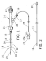
- Fig. 1 depicts an illustrative sheath of the present invention, shown in combination with a dilator and a manifold;
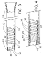
- Fig. 2 depicts the dilator of Fig. 1 removed from the sheath
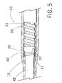
- Fig. 3 depicts a partially sectioned view of sheath of Figure 1, with the dilator removed;
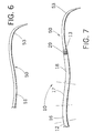
- Fig. 4 depicts a partially sectioned view of the inventive sheath enveloped by a heat shrink tube, prior to heating of the sheath;
- Fig. 5 depicts a partially sectioned view of the sheath of Fig. 4 after the sheath outer layer has been melted and prior to removal of the heat shrink tube;
- Fig. 6 depicts a catheter that may be used with the inventive sheath.
- Fig. 7 depicts the catheter and sheath in combination.
- Fig. 1 depicts an illustrative flexible, kink-resistant, introducer sheath 10, according to an embodiment of the present invention. Sheath 10 is shown in combination with a dilator 11 and a connector valve 14.
- sheath 10 includes an outer tube 20, which is provided with a proximal end 15 and a distal end 13.
- Proximal end 15 may be formed into either a straight or a flared configuration in conventional fashion.
- Distal end 13 may be tapered, and may have a straight shape, a curved shape, a J-shape or any other shape that will facilitate the entry of the distal end 13 into a vascular anatomy.
- Outer tube 20 comprises a plurality of discrete segments 12, 16, 17, 18 of different durometer.
- connector valve 14 comprises a well-known Tuohy-Borst Side-Arm Adapter.
- the Tuohy-Borst Adapter includes a valve seal (not shown) for minimizing blood loss during insertion of the sheath.
- Adapters of this type are available from Cook Incorporated, of Bloomington, IN.
- Connector valve 14 allows a user to inject fluid through the sheath 10 into the vascular anatomy.
- the connector valve shown includes a "Y"- connector 21. Arm 28 of Y-connector 21 is coupled to a suitable second connector 22, which is coupled to a third connector 23.
- a suitable polymeric tube such as polyvinyl tube 24, extends from connector 23 to a high-flow three-way stopcock connector 25, for use in introducing and aspirating fluids therethrough.
- the high-flow three-way stopcock connector 25 includes a plug 25a for selectively allowing and preventing fluids from flowing through the stopcock connector.
- connector valve 14 need not be of the exact configuration shown, and that any manifold of the type commonly used in the art for such purposes may be substituted for connector valve shown. If desired, such manifolds may be provided with additional side-arms to enhance the utility of the device, such as the introduction and/or aspiration of additional fluids.
- dilator 11 has a proximal end 27 and a distal end 19. Distal end 19 is tapered for accessing and dilating a vascular access site.
- Dilator 11 includes a lumen therethrough for passage of a wire guide using, for example, the well-known Seldinger technique.
- Dilator 11 is sized such that when its proximal end 27 abuts against the proximal end of connector valve 14, approximately 10-15 cm of dilator distal end 19 protrudes from the distal end of sheath 10.
- the dilator has an outside diameter of about 4-8 French.
- a preferred dilator is a Coons dilator, available from Cook Incorporated, of Bloomington, IN.
- Fig. 3 depicts an enlarged, partially sectioned view of introducer sheath 10 of Fig. 1, with dilator 11 and connector valve 14 removed for clarity.
- Sheath 10 comprises an inner tube 31, a flat wire coil 33 wound or compression fitted around inner tube 31, and an outer tube 20.
- outer tube 20 is mechanically connected to a roughened outer surface 32 of the inner tube 31 through the spacings of the coil 33.
- Outer surface 32 of the inner tube 31 may be chemically etched in well-known manner for forming the roughened outer surface.
- inner tube 31 comprises a lubricious material, preferably a fluorocarbon such as polytetrafluoroethylene (PTFE).
- PTFE polytetrafluoroethylene
- inner tube 31 has a uniform inside diameter having an inside diameter ranging from about 4 to 10 French, more preferably, from 5 to 8 French.
- the wall thickness of inner tube 31 is generally about 0.0015 inch (0.038 mm). These dimensions are exemplary only, and the inner diameter may be constructed to be of any size necessary to accomplish the purposes for which the sheath is to be employed.
- the lubricious PTFE material presents a slippery inner surface 34 to allow easy insertion and withdrawal of the dilator 11 as well as other catheters and medical apparatus. Inner surface 34 is also smooth and nonporous for minimizing the formation of blood clots and other thrombi thereon.
- the uniform inner diameter of inner tube 31 extends the entire length of passageway 30 to enable passage of the largest possible diameter catheter or other interventional device therethrough.
- the wall of the inner tube 31 has sufficient radial rigidity to prevent the turns of compression-fitted coil 33 from protruding into inner tube passageway 30.
- Coil 33 may be compression fitted or wound around inner tube 31.
- the coil includes a plurality of turns, and preferably includes uniform spacings between the coil turns.
- coil 33 is stainless steel flat wire, although other biologically compatible metals, alloys (including super-elastic alloys), and composite materials may also be utilized.
- a flat wire coil is preferred, coils of other cross-sectional dimensions, such as round wire, may also be utilized.
- coil 33 is preferably formed from wire that is about 0.003 inch thick by 0.012 inch wide (0.076 mm by 0.30 mm).
- the ends of coil 33 are spaced approximately 5 mm from the distal end of inner tube 31 and approximately 1.4 cm from the proximal end.
- the turns of coil 33 are uniformly spaced apart by approximately 0.3 mm. Although it is preferred to use coils having uniformly spaced turns and a constant pitch, this is not required and coils spaced non-uniform distances, or at a varying coil turn pitch may also be used.
- Sheath 10 may be constructed to have any length required to fulfill its intended purposes. In most cases, the sheath will have a length between about 50 and 125 cm, and most generally, between about 70 and 100 cm. Generally, the lengths of inner tube 31 and outer tube 20 are the same, and the length of coil 33 will be less than the length of the inner and outer tubes, for the purposes recited in the previous paragraph.
- the distal portion for example the distal 60 cm, cm may be covered with a hydrophilic coating, such as AQ® hydrophilic coating.
- Outer tube 20 is formed of any well-known polymer commonly used for such purpose.
- outer tube 20 comprises a heat formable polyamide material, such as nylon. This heat formable material melts upon heating, such that portions flow between the turns of the coil and bond to the roughened outer surface of the inner tube.
- the pre-melt thickness of the wall of the nylon tube is approximately 0.0065 inch (0.17 mm) for exemplary sheaths of 5-8 French.
- inner tube 31 is positioned over a stainless steel mandril 42 as shown in Fig. 4, such that the inner diameter (ID) of the inner tube 31 substantially matches the outer diameter (OD) of the mandril.
- ID inner diameter
- OD outer diameter
- a flat wire coil 33 having an ID less than the OD of inner tube 31 is compression fitted or wound around the inner tube. Suitable techniques for compression fitting and winding coils are well known in the art.
- a long, or "major” segment 12, such as a segment having a length of e.g. 50-100 cm , or even more preferably 55-85 cm, of the outer tube 20 is longitudinally positioned around inner tube 31 and flat wire coil 33.
- major segment 12 has a durometer in the range of about 70 to 80 on the Shore D scale, most preferably about 75.
- durometer as used herein is a common term of art that is normally used to refer to the resistance of materials such as rubber or plastics to deformation, typically to deformation by an indenter of specific size and shape under a load.
- the Shore D scale is a common measure of hardness of plastic materials. A high durometer material is one that is relatively inflexible (e.g. harder), whereas a low durometer material is one that is relatively flexible (e.g. softer). All durometer readings herein are measured on the Shore D scale.
- a plurality of smaller, or "minor”, tube segments 16, 17, 18 of decreasing durometer, to be described in greater detail, extend from major segment 12 to the distal end of the sheath.
- the length of the major segment comprises at least 50% of the length of the outer tube, more preferably at least 75%, and even more preferably at least 80-85%.
- segment 16 is then positioned such that it abuts the distal end of segment 12.
- segment 16 has a length of about 3 cm, and a durometer in the range of about 53-63, preferably 58.
- Segment 17 is positioned to abut the distal end of segment 16.
- Segment 17 has a length of about 5 cm, and a durometer of about 35 to 45, preferably 40.
- segment 18 is positioned to abut the distal end of segment 17. Segment 18 has a length of about 3.2 cm, and a durometer of about 20 to 30, preferably 25.
- segments 16, 17 and 18 are also longitudinally positioned around the inner tube 31 and flat wire coil 33, in the same manner as segment 12, although if desired, coil 33 may be sized to terminate prior to one or more of the distal-most segments.
- a radiopaque marker band 29 may be slid under distal segment 18. Marker bands are well known in the art, and a band formed of any conventional materials may be utilized. Preferably, marker band 29 is formed of platinum.
- the reduction in durometer of segments 12, 16, 17, 18 provides a gradual step-down at the distal end of sheath 10 from a relatively stiff shaft portion 12 to a relatively soft distal tip portion 18 without abrupt transitions.
- the stiff shaft portion 12 provides the shaft with trackability and non-kinking support over a rather long portion of the sheath, and the flexible distal tip enables the tip to be as benign as possible. An abrupt transition may otherwise prevent tracking of the sheath into remote areas of the vasculature, e.g., the common carotid from the aorta.
- heat shrink tube 40 is positioned such that it envelopes inner tube 31, flat wire coil 33, and outer tube segments 12, 16, 17, 18, as shown in Fig. 4.
- Heat shrink tube 40 is somewhat longer than outer tube 20, and is preferably formed of a fluorinated ethylene propylene heat shrinkable material.
- heat shrinkable tubing 40 shrinks and causes outer tube segments 12, 16, 17, 18 to melt.
- the melted segments flow between the uniform spacings of the turns of coil 33 and mechanically connect to roughened outer surface 32 of inner tube 31, as shown in Fig. 5.
- the shrink tube is then cut off, and the mandril is removed.
- the heat formable nylon tube is self-leveling, which provides a uniform outer diameter surface for outer tube 20.
- Distal end 13 may be tapered to provide a smooth transition to inner dilator 11 or to a catheter.
- the respective longitudinal ends of the four segments 12, 16, 17, 18 of different durometer nylon tubing bond/melt together to form a single sheath with three transitions, namely the transition between segments 12 and 16, the transition between segments 16 and 17, and the transition between segments 17 and 18.
- the varying durometers of the segments of outer tube 20 transition the sheath from a rigid shaft at outer tube segment 12 to a soft tip at segment 18.
- Other details of the construction of sheath 10 are conventional and need not be repeated here. Such details are discussed, among others, in U.S. Patent No. 5,380,304 .
- sheath 10 is used for placing an interventional device, such as a stent, into a patient's carotid artery.
- an interventional device such as a stent
- a needle puncture is made through the patient's skin into a target vessel.
- a wire guide is then inserted through a bore in the needle into the vessel in accordance with the Seldinger technique, and the needle is withdrawn.
- a dilator and sheath combination as shown in Fig. 1 is then threaded over the wire guide.
- the dilator dilates the opening and provides a path to the desired area of the vasculature, in this case the aortic arch.
- a dilator may be inserted followed by introduction of the sheath. In either case, once the distal end of the dilator reaches the aortic arch, the dilator is withdrawn from the sheath.
- FIG. 6 illustrates one example of a catheter that may be used to access a smaller branch vessel in the patient's vasculature.
- Catheter 50 has a proximal end 51 and a distal end 53. If desired, distal end 53 may be formed of a radiopaque material.
- catheter 50 comprises a nylon construction having a stainless steel braid within the nylon to provide enhanced torque.
- Distal end 53 of catheter 50 may include a curve or angle of a pre-selected configuration, to enable distal end 53 to mimic the vascular pattern at the target site to the extent feasible, and thereby facilitate insertion of the catheter and wire guide into the selected smaller vessel site.
- Catheter 50 may be constructed or formed to have virtually any shape that may be desired for a particular purpose.
- Fig. 7 shows catheter 50 inserted into sheath 10. As shown, the distal end 53 of catheter 50 extends in the distal direction beyond the distal end 13 of sheath 10.
- Conventional marker band 29 may be provided at the distal end of sheath 10.
- the smaller neurocirculation vessels that may be a target of the technician comprise a tortuous pathway that branches off from the aorta.
- the neurocirculation target vessels include arch vessels like the subclavian vessels, the left common carotid and the innominate/brachiocephalic arteries.
- the curved distal end 53 of catheter 50 can be manipulated to enter into the desired area.
- the sheath can then be telescoped over the catheter that previously protruded from the end of the sheath inside the desired remote vessel, and catheter 50 can be removed.
- An interventional procedure such as the placement of a stent (with or without a balloon), may now be performed.
- the flexibility of the sheath at the distal tip enables it to be benign in, e.g., the common carotid as the beating heart causes it to bob up and down.
- a particularly preferred catheter that may be used with the inventive sheath is a selected one of the family of catheters known as SLIP-CATH® catheters, manufactured by Cook Incorporated, of Bloomington, IN.
- SLIP-CATH® catheters are provided in a variety of sizes and distal-end configurations, to enable the physician to select an optimally-shaped catheter for a particular application.
- SLIP-CATH® catheters are provided in configurations particularly suitable for cerebral or visceral use.
- the catheter shown in Fig. 6 includes merely one example of a distal tip configuration that may be utilized. Those skilled in the art will recognize that many other tip configurations may be utilized for a particular application.
- the catheters may be provided in any convenient length from about 40 to 150 cm. When utilized in combination with a sheath having a length of from about 70 to 100 cm, the optimal lengths of such catheters are about 120 to 140 cm, preferably 125 cm.
- the catheter be sized such that its outer diameter is between about 0.0005 and 0.004 inch (0.013 and 0.10 mm), less than the inner diameter of the sheath 10.
- the outer diameter of the catheter is in range of about 0.0995 inch (2.53 mm) to about 0.096 inch (2.44 mm). More preferably, the difference in inner diameter of the sheath 10 to the catheter is about 0.001 inch (0.025 mm) to about 0.003 inch (0.076 mm).
- the close tolerance between the sheath and the catheter prevents the catheter from knocking loose any plaque that may be lining the inside of the vessels traversed by the sheath and the catheter. This is often referred to as the "snowplowing" effect. Having a diameter difference is this range is also advantageous because it provides a smooth transition between the catheter and the sheath as the catheter is advanced through the sheath to a vessel within the vasculature of the patient. If the diameter difference is much greater than about 0.004 inch (0.10 mm), a ledge-type surface may be created. Upon insertion of the catheter or sheath into the vasculature, the presence of such a ledge could damage the anatomy of any vessel that is traversed by the component as it is being advanced.
- At least the distal portion of the catheter include a hydrophilic coating, such as the AQ® hydrophilic coating.
- a hydrophilic coating greatly increases the lubricity of the catheter when compared to non-coated catheters, and provides for ease of insertion and/or removal of the catheter.
- the hydrophilic coating will comprise about the distal 60 cm of the catheter.
- a dilator 11 it is not necessary to use a dilator 11 in all applications.
- the combination of sheath and catheter 50 can be used to dilate the initial opening, and the step of using a separate dilator 11 may be omitted.
- the durometer ranges recited above are preferred because they provide a sheath that has the versatility to be used for a wide variety of applications. However, those skilled in the art will recognize that other durometer ranges may be substituted, and indeed, may be preferred for any specific application.
- the scope of the invention includes any sheath having a gradual decrease in durometer at the distal end to permit manipulation of the sheath such that it can be introduced into small diameter tortuous passages in the vasculature. Preferably, it is only the extreme distal end of the sheath, such as the distal 25 to 30 cm, preferably 10 to 15 cm, that is varied in durometer from the main body 12 of the sheath, although additional variations are possible.
- Decreasing the durometer over a plurality of segments, such as the three segments 16, 17, 18 over the distal 11.2 cm of the exemplary sheath described, provides a gradual decrease in stiffness, such as the described durometer decrease from 75 to 25, in precisely the area of the sheath that is often most in need of such variation.
- those skilled in the art may prefer a sheath having a more gradual decrease in durometer over a greater, or lesser, length of the sheath, which variation is also within the scope of the invention.
- a sheath can be constructed according to the teachings of the present invention to conform specifically to virtually any particular vascular configuration.
- the dimensions provided above are only exemplary, but are believed to provide a sheath having sufficient versatility to be useful in a multitude of applications.
Claims (10)
- Gaine d'introducteur souple résistant au pliage (10) comprenant une extrémité proximale (15) et une extrémité distale (13) conçues pour être introduites dans le système vasculaire d'un patient ; un tube intérieur (31) possédant un passage (30) s'étendant longitudinalement dans celui-ci, ledit passage présentant un diamètre essentiellement uniforme ; un serpentin (33) comprenant une pluralité de spires positionnées longitudinalement autour dudit tube intérieur (31), lesdites spires présentant un espace prédéterminé entre celles-ci ; et un tube extérieur (20) positionné longitudinalement autour dudit serpentin (33) et dudit tube intérieur (31) et raccordé audit tube intérieur (31) à travers des espaces (39) entre lesdites spires, ledit tube extérieur (20) comprenant une pluralité de segments de tube (12, 16, 17, 18), lesdits segments étant alignés en ordre décroissant de dureté à partir de ladite extrémité proximale (15) jusqu'à ladite extrémité distale (13) et comprenant un segment principal d'une dureté supérieure, caractérisée en ce que ledit tube extérieur (20) comprend trois segments secondaires d'une dureté inférieure, dans lequel chacun desdits segments secondaires n'excède pas 5 cm en longueur.
- Gaine d'introducteur selon la revendication 1, dans laquelle la dureté dudit segment principal se situe entre environ 70 et 80, et dans laquelle les duretés des segments secondaires se situent entre environ 20 et 65.
- Gaine d'introducteur selon la revendication 2, dans laquelle lesdits segments secondaires ont des duretés situées entre 53 et 63, 35 et 45, et 20 et 30, respectivement.
- Gaine d'introducteur selon la revendication 3, dans laquelle la dureté dudit segment principal est d'environ 75, et les duretés des segments secondaires sont d'environ 58, 40 et 25, respectivement.
- Gaine d'introducteur selon l'une des revendications 3 et 4, dans laquelle les longueurs desdits segments secondaires, mesurées en séquence à partir du segment principal, sont d'environ 3 cm, 5 cm et 3,2 cm, respectivement.
- Assemblage d'une gaine et d'un cathéter, comprenant une gaine d'introducteur selon l'une quelconque des revendications précédentes et un cathéter (50) possédant une extrémité proximale (51) et une extrémité distale (53), ledit cathéter étant dimensionné pour être inséré dans ledit passage (30) du tube intérieur et dimensionné en outre de sorte qu'au moins une partie de ladite extrémité distale (53) du cathéter s'étend au-delà de l'extrémité distale (13) de ladite gaine (10) lorsque ledit cathéter (50) est inséré dans ledit passage (30) ; ledit cathéter (50) ayant un diamètre extérieur qui est de 0,013 à 0,10 mm inférieur au diamètre dudit passage (30).
- Assemblage selon la revendication 6, dans lequel ledit diamètre extérieur est de 0,025 à 0,076 mm inférieur au diamètre dudit passage.
- Assemblage selon l'une des revendications 6 et 7, dans lequel au moins l'extrémité distale de la surface extérieure de ladite gaine (10) est recouverte d'un composé hydrophile.
- Assemblage selon l'une des revendications 6, 7 et 8, dans lequel au moins l'extrémité distale de la surface extérieure du cathéter est recouverte d'un composé hydrophile.
- Assemblage selon l'une quelconque des revendications 6 à 9, dans lequel l'extrémité distale dudit cathéter possède une forme qui permet d'accéder à un vaisseau du corps.
Priority Applications (2)
| Application Number | Priority Date | Filing Date | Title |
|---|---|---|---|
| EP07018179.7A EP1872820B1 (fr) | 2003-04-28 | 2004-04-26 | Gaine d'intubateur flexible avec duromètre variable |
| DK07018179.7T DK1872820T3 (en) | 2003-04-28 | 2004-04-26 | Flexible insertion sheath with varying durometer |
Applications Claiming Priority (2)
| Application Number | Priority Date | Filing Date | Title |
|---|---|---|---|
| US46638403P | 2003-04-28 | 2003-04-28 | |
| PCT/US2004/012795 WO2004096338A1 (fr) | 2003-04-28 | 2004-04-26 | Gaine d'introducteur souple a durometre variable |
Related Child Applications (1)
| Application Number | Title | Priority Date | Filing Date |
|---|---|---|---|
| EP07018179.7A Division EP1872820B1 (fr) | 2003-04-28 | 2004-04-26 | Gaine d'intubateur flexible avec duromètre variable |
Publications (2)
| Publication Number | Publication Date |
|---|---|
| EP1631343A1 EP1631343A1 (fr) | 2006-03-08 |
| EP1631343B1 true EP1631343B1 (fr) | 2007-11-14 |
Family
ID=33418371
Family Applications (2)
| Application Number | Title | Priority Date | Filing Date |
|---|---|---|---|
| EP07018179.7A Expired - Lifetime EP1872820B1 (fr) | 2003-04-28 | 2004-04-26 | Gaine d'intubateur flexible avec duromètre variable |
| EP04760386A Expired - Lifetime EP1631343B1 (fr) | 2003-04-28 | 2004-04-26 | Gaine d'introducteur souple a durometre variable |
Family Applications Before (1)
| Application Number | Title | Priority Date | Filing Date |
|---|---|---|---|
| EP07018179.7A Expired - Lifetime EP1872820B1 (fr) | 2003-04-28 | 2004-04-26 | Gaine d'intubateur flexible avec duromètre variable |
Country Status (9)
| Country | Link |
|---|---|
| US (1) | US11000670B2 (fr) |
| EP (2) | EP1872820B1 (fr) |
| JP (1) | JP4579910B2 (fr) |
| AT (1) | ATE378085T1 (fr) |
| AU (1) | AU2004233877B2 (fr) |
| CA (1) | CA2523487C (fr) |
| DE (1) | DE602004010104T2 (fr) |
| DK (2) | DK1872820T3 (fr) |
| WO (1) | WO2004096338A1 (fr) |
Cited By (1)
| Publication number | Priority date | Publication date | Assignee | Title |
|---|---|---|---|---|
| US11793977B2 (en) | 2018-05-16 | 2023-10-24 | Abiomed, Inc. | Peel-away sheath assembly |
Families Citing this family (36)
| Publication number | Priority date | Publication date | Assignee | Title |
|---|---|---|---|---|
| US20060207604A1 (en) * | 2003-06-06 | 2006-09-21 | Radlyn Llc | Intubation device and method of use |
| JP2008531213A (ja) * | 2005-03-02 | 2008-08-14 | クック インコーポレイテッド | 挿入器シース |
| US8177741B2 (en) * | 2005-04-12 | 2012-05-15 | Cook Medical Technologies Llc | Catheter with superelastic retention device |
| US7674240B2 (en) * | 2005-12-20 | 2010-03-09 | Abbott Cardiovascular Systems Inc. | Method and apparatus for controlled vessel occlusion |
| US8246574B2 (en) * | 2006-04-21 | 2012-08-21 | Abbott Laboratories | Support catheter |
| US20090030400A1 (en) * | 2007-07-25 | 2009-01-29 | Arani Bose | System and method for intracranial access |
| US20100160862A1 (en) * | 2008-12-22 | 2010-06-24 | Cook Incorporated | Variable stiffness introducer sheath with transition zone |
| WO2010075445A1 (fr) | 2008-12-23 | 2010-07-01 | Silk Road Medical, Inc. | Méthodes et systèmes pour le traitement d'un accident cérébral ischémique aigu |
| US20110238041A1 (en) * | 2010-03-24 | 2011-09-29 | Chestnut Medical Technologies, Inc. | Variable flexibility catheter |
| US9327096B2 (en) | 2011-06-02 | 2016-05-03 | Atrium Medical Corporation | Body lumen fluid delivery device |
| US20130150767A1 (en) * | 2011-06-21 | 2013-06-13 | Eduard Tsyrulnykov | Vascular access device for hemodialysis |
| US10779855B2 (en) | 2011-08-05 | 2020-09-22 | Route 92 Medical, Inc. | Methods and systems for treatment of acute ischemic stroke |
| JP2014521462A (ja) | 2011-08-05 | 2014-08-28 | シルク・ロード・メディカル・インコーポレイテッド | 急性虚血性脳卒中を治療するための方法及びシステム |
| US8986226B2 (en) | 2011-10-05 | 2015-03-24 | Coeur, Inc. | Guidewire positioning tool |
| US9072624B2 (en) | 2012-02-23 | 2015-07-07 | Covidien Lp | Luminal stenting |
| US9522257B2 (en) | 2012-03-30 | 2016-12-20 | Abbott Cardiovascular Systems Inc. | Integrated controlled volume inflator device, components, and methods of use |
| US9364603B2 (en) | 2013-06-21 | 2016-06-14 | Eduard Tsyrulnykov | Multiple layer dilator single point vascular access device |
| US8968383B1 (en) | 2013-08-27 | 2015-03-03 | Covidien Lp | Delivery of medical devices |
| US9782186B2 (en) | 2013-08-27 | 2017-10-10 | Covidien Lp | Vascular intervention system |
| US9265512B2 (en) | 2013-12-23 | 2016-02-23 | Silk Road Medical, Inc. | Transcarotid neurovascular catheter |
| US9241699B1 (en) | 2014-09-04 | 2016-01-26 | Silk Road Medical, Inc. | Methods and devices for transcarotid access |
| US11027104B2 (en) | 2014-09-04 | 2021-06-08 | Silk Road Medical, Inc. | Methods and devices for transcarotid access |
| US11065019B1 (en) | 2015-02-04 | 2021-07-20 | Route 92 Medical, Inc. | Aspiration catheter systems and methods of use |
| AU2016215229B2 (en) | 2015-02-04 | 2020-05-07 | Route 92 Medical, Inc. | Rapid aspiration thrombectomy system and method |
| US10582914B2 (en) | 2016-01-15 | 2020-03-10 | Covidien Lp | Navigable endobronchial tool to access tissue outside a bronchus |
| CN212038548U (zh) | 2016-12-08 | 2020-12-01 | 阿比奥梅德公司 | 导入器毂制造组件 |
| US10376396B2 (en) | 2017-01-19 | 2019-08-13 | Covidien Lp | Coupling units for medical device delivery systems |
| AU2018359898A1 (en) | 2017-11-06 | 2020-04-23 | Abiomed, Inc. | Peel away hemostasis valve |
| US11413176B2 (en) | 2018-04-12 | 2022-08-16 | Covidien Lp | Medical device delivery |
| US11123209B2 (en) | 2018-04-12 | 2021-09-21 | Covidien Lp | Medical device delivery |
| US11071637B2 (en) | 2018-04-12 | 2021-07-27 | Covidien Lp | Medical device delivery |
| US10786377B2 (en) | 2018-04-12 | 2020-09-29 | Covidien Lp | Medical device delivery |
| EP3793660A2 (fr) | 2018-05-17 | 2021-03-24 | Route 92 Medical, Inc. | Systèmes de cathéter d'aspiration et procédés d'utilisation |
| US11413174B2 (en) | 2019-06-26 | 2022-08-16 | Covidien Lp | Core assembly for medical device delivery systems |
| US20220161003A1 (en) | 2020-11-26 | 2022-05-26 | Avia Vascular, Llc | Blood collection devices, systems, and methods |
| US11944558B2 (en) | 2021-08-05 | 2024-04-02 | Covidien Lp | Medical device delivery devices, systems, and methods |
Family Cites Families (200)
| Publication number | Priority date | Publication date | Assignee | Title |
|---|---|---|---|---|
| US2437542A (en) * | 1944-05-05 | 1948-03-09 | American Catheter Corp | Catheter-type instrument |
| US2857915A (en) | 1956-04-02 | 1958-10-28 | David S Sheridan | X-ray catheter |
| US3174851A (en) * | 1961-12-01 | 1965-03-23 | William J Buehler | Nickel-base alloys |
| US3370587A (en) * | 1962-07-17 | 1968-02-27 | Fernando R. Vizcarra | Method of introducing a catheter into a body vessel |
| US3228894A (en) * | 1962-12-24 | 1966-01-11 | Us Catheter & Instr Corp | Fluorocarbon tungsten members |
| US3416531A (en) | 1964-01-02 | 1968-12-17 | Edwards Miles Lowell | Catheter |
| US3351463A (en) | 1965-08-20 | 1967-11-07 | Alexander G Rozner | High strength nickel-base alloys |
| US3485234A (en) | 1966-04-13 | 1969-12-23 | Cordis Corp | Tubular products and method of making same |
| US3568660A (en) * | 1967-11-20 | 1971-03-09 | Battelle Development Corp | Pacemaker catheter |
| US3608555A (en) | 1968-12-31 | 1971-09-28 | Chemplast Inc | Radio opaque and optically transparent tubing |
| US3612038A (en) | 1969-02-03 | 1971-10-12 | Becton Dickinson Co | Preformable catheter package assembly and method of preforming |
| US3618614A (en) | 1969-05-06 | 1971-11-09 | Scient Tube Products Inc | Nontoxic radiopaque multiwall medical-surgical tubings |
| US3634924A (en) | 1970-04-20 | 1972-01-18 | American Hospital Supply Corp | Method of making multilumen balloon catheter |
| US3753700A (en) | 1970-07-02 | 1973-08-21 | Raychem Corp | Heat recoverable alloy |
| US3866599A (en) * | 1972-01-21 | 1975-02-18 | Univ Washington | Fiberoptic catheter |
| US3749134A (en) | 1972-02-02 | 1973-07-31 | Sunlite Plastics Inc | Radiographically opaque plastic tubing |
| US3890976A (en) * | 1972-10-26 | 1975-06-24 | Medical Products Corp | Catheter tip assembly |
| US3924632A (en) | 1972-12-07 | 1975-12-09 | William A Cook | Fiber glass reinforced catheter |
| US3890977A (en) * | 1974-03-01 | 1975-06-24 | Bruce C Wilson | Kinetic memory electrodes, catheters and cannulae |
| US3935857A (en) * | 1974-07-31 | 1976-02-03 | Co Eddy D | Cardiac catheter |
| US3995623A (en) | 1974-12-23 | 1976-12-07 | American Hospital Supply Corporation | Multipurpose flow-directed catheter |
| US4361152A (en) | 1975-05-27 | 1982-11-30 | The Kendall Company | Catheter |
| SE390886B (sv) | 1975-06-23 | 1977-01-31 | Siemens Elema Ab | Kateter for selektiv coronar arteriografi av venster coronararter |
| US4015601A (en) * | 1975-10-14 | 1977-04-05 | General Atomic Company | Blood access device |
| US4029104A (en) * | 1976-03-08 | 1977-06-14 | Kerber Charles W | Calibrated leak balloon micro-catheter |
| US4024873A (en) * | 1976-05-24 | 1977-05-24 | Becton, Dickinson And Company | Balloon catheter assembly |
| US4099425A (en) | 1976-06-01 | 1978-07-11 | Samuel Moore And Company | Method of making push-pull cable conduit and product |
| US4184497A (en) * | 1977-08-26 | 1980-01-22 | University Of Utah | Peritoneal dialysis catheter |
| JPS5456672A (en) * | 1977-10-14 | 1979-05-07 | Toray Ind Inc | High polymer tube having modified inner surface |
| US4169464A (en) | 1977-12-16 | 1979-10-02 | Cordis Corporation | Catheter for selective catheterization of aortic branches |
| US4196731A (en) * | 1978-03-17 | 1980-04-08 | Baxter Travenol Laboratories, Inc. | Silicone-containing thermoplastic polymers for medical uses |
| DE2813276C2 (de) | 1978-03-28 | 1985-10-03 | Dr. Eduard Fresenius, Chemisch-pharmazeutische Industrie KG Apparatebau KG, 6380 Bad Homburg | Mandrin für Katheter |
| US4306566A (en) | 1978-06-07 | 1981-12-22 | Gesco International, Inc. | Cholangiogram catheter |
| US4276874A (en) | 1978-11-15 | 1981-07-07 | Datascope Corp. | Elongatable balloon catheter |
| CA1153264A (fr) | 1979-02-08 | 1983-09-06 | Hidenaga Yoshimura | Fil guide et catheter vasculaire |
| US4248234A (en) * | 1979-03-08 | 1981-02-03 | Critikon, Inc. | Catheter with variable flexural modulus and method of using same |
| US4279252A (en) | 1979-08-24 | 1981-07-21 | Martin Michael T | X-ray scaling catheter |
| US4385635A (en) * | 1980-04-25 | 1983-05-31 | Ruiz Oscar F | Angiographic catheter with soft tip end |
| US4329993A (en) * | 1980-06-18 | 1982-05-18 | American Hospital Supply Corporation | Catheter with trans-luminal electrical conductor |
| US4368730A (en) * | 1981-02-12 | 1983-01-18 | Nigel Sharrock | Intravenous catheter |
| US4425919A (en) * | 1981-07-27 | 1984-01-17 | Raychem Corporation | Torque transmitting catheter apparatus |
| DE8132839U1 (de) * | 1981-11-10 | 1982-03-11 | B. Braun Melsungen Ag, 3508 Melsungen | Versteifungskern fuer einen katheterschlauch |
| JPS5886129A (ja) * | 1981-11-17 | 1983-05-23 | 旭光学工業株式会社 | 内視鏡の可撓管及びその製造方法 |
| US4516972A (en) * | 1982-01-28 | 1985-05-14 | Advanced Cardiovascular Systems, Inc. | Guiding catheter and method of manufacture |
| US4484586A (en) | 1982-05-27 | 1984-11-27 | Berkley & Company, Inc. | Hollow conductive medical tubing |
| US4464176A (en) | 1982-06-04 | 1984-08-07 | Mallinckrodt, Inc. | Blood vessel catheter for medicine delivery and method of manufacture |
| US4498473A (en) * | 1982-12-07 | 1985-02-12 | Gereg Gordon A | Variable stiffness tracheal tube |
| US4563181A (en) * | 1983-02-18 | 1986-01-07 | Mallinckrodt, Inc. | Fused flexible tip catheter |
| US4596563A (en) * | 1983-06-09 | 1986-06-24 | Cordis Corporation | Thin-walled multi-layered catheter having a fuseless tip |
| US4531943A (en) | 1983-08-08 | 1985-07-30 | Angiomedics Corporation | Catheter with soft deformable tip |
| US4571240A (en) * | 1983-08-12 | 1986-02-18 | Advanced Cardiovascular Systems, Inc. | Catheter having encapsulated tip marker |
| US4577543A (en) * | 1983-08-18 | 1986-03-25 | American Hospital Supply Corporation | Construction of a monolithic reinforced catheter with flexible portions |
| JPS60126170A (ja) * | 1983-12-14 | 1985-07-05 | テルモ株式会社 | カテ−テルとその製造方法 |
| US4694838A (en) | 1984-01-30 | 1987-09-22 | Mallinckrodt, Inc. | Loop coronary catheter |
| US4636346A (en) * | 1984-03-08 | 1987-01-13 | Cordis Corporation | Preparing guiding catheter |
| US4551292A (en) | 1984-04-05 | 1985-11-05 | Angiomedics, Inc. | Method for making a catheter with a soft, deformable tip |
| US4547193A (en) | 1984-04-05 | 1985-10-15 | Angiomedics Incorporated | Catheter having embedded multi-apertured film |
| US4696304A (en) | 1984-09-10 | 1987-09-29 | Thomas J. Fogarty | Thermodilution flow-directed catheter assembly and method |
| JPS6171065A (ja) | 1984-09-13 | 1986-04-11 | テルモ株式会社 | カテ−テルイントロデユ−サ |
| US4705511A (en) | 1985-05-13 | 1987-11-10 | Bipore, Inc. | Introducer sheath assembly |
| US4639246A (en) * | 1985-09-09 | 1987-01-27 | Animal Healthcare Products | Catheter |
| US4806182A (en) * | 1985-10-15 | 1989-02-21 | Schneider-Shiley (U.S.A.) Inc. | Method of bonding a hub to a Teflon-lined catheter body |
| US4627844A (en) | 1985-10-30 | 1986-12-09 | High Voltage Engineering Corporation | Tri-layer tubing |
| JPH025799Y2 (fr) * | 1986-02-07 | 1990-02-13 | ||
| US4758221A (en) | 1986-02-18 | 1988-07-19 | St. Louis University | Catheter with a tip manipulation feature |
| US4721115A (en) * | 1986-02-27 | 1988-01-26 | Cardiac Pacemakers, Inc. | Diagnostic catheter for monitoring cardiac output |
| US4739768B2 (en) * | 1986-06-02 | 1995-10-24 | Target Therapeutics Inc | Catheter for guide-wire tracking |
| US4775371A (en) | 1986-09-02 | 1988-10-04 | Advanced Cardiovascular Systems, Inc. | Stiffened dilatation catheter and method of manufacture |
| US4747840A (en) * | 1986-09-17 | 1988-05-31 | Ladika Joseph E | Selective pulmonary arteriograph catheter |
| FR2608037A1 (fr) * | 1986-12-10 | 1988-06-17 | Lenck Lucien | Methode d'intubation destinee a permettre la transplantation de l'oeuf ou de la matiere embryonnaire, et moyens pour sa mise en oeuvre |
| US4886506A (en) | 1986-12-23 | 1989-12-12 | Baxter Travenol Laboratories, Inc. | Soft tip catheter |
| US4762130A (en) | 1987-01-15 | 1988-08-09 | Thomas J. Fogarty | Catheter with corkscrew-like balloon |
| US4817613A (en) * | 1987-07-13 | 1989-04-04 | Devices For Vascular Intervention, Inc. | Guiding catheter |
| US4863442A (en) | 1987-08-14 | 1989-09-05 | C. R. Bard, Inc. | Soft tip catheter |
| US4840622A (en) * | 1987-10-06 | 1989-06-20 | Menlo Care, Inc. | Kink resistant catheter |
| US4883058A (en) | 1988-01-06 | 1989-11-28 | Sherwood Medical Company | Right coronary angiographic method |
| US5078702A (en) * | 1988-03-25 | 1992-01-07 | Baxter International Inc. | Soft tip catheters |
| US4884579A (en) | 1988-04-18 | 1989-12-05 | Target Therapeutics | Catheter guide wire |
| US4963306A (en) | 1988-07-14 | 1990-10-16 | Novoste Corporation | Method for making fuseless soft tip angiographic catheter |
| US5088991A (en) * | 1988-07-14 | 1992-02-18 | Novoste Corporation | Fuseless soft tip angiographic catheter |
| US4898591A (en) * | 1988-08-09 | 1990-02-06 | Mallinckrodt, Inc. | Nylon-PEBA copolymer catheter |
| US4994069A (en) * | 1988-11-02 | 1991-02-19 | Target Therapeutics | Vaso-occlusion coil and method |
| US5037404A (en) | 1988-11-14 | 1991-08-06 | Cordis Corporation | Catheter having sections of variable torsion characteristics |
| US4985022A (en) | 1988-11-23 | 1991-01-15 | Med Institute, Inc. | Catheter having durable and flexible segments |
| US4960410A (en) * | 1989-03-31 | 1990-10-02 | Cordis Corporation | Flexible tubular member for catheter construction |
| US5045072A (en) | 1989-06-13 | 1991-09-03 | Cordis Corporation | Catheter having highly radiopaque, flexible tip |
| US5057083A (en) | 1989-07-25 | 1991-10-15 | C. R. Bard, Inc. | Vascular dilator with truncated tip |
| US5248305A (en) | 1989-08-04 | 1993-09-28 | Cordis Corporation | Extruded tubing and catheters having helical liquid crystal fibrils |
| US5156785A (en) | 1991-07-10 | 1992-10-20 | Cordis Corporation | Extruded tubing and catheters having increased rotational stiffness |
| US5116652A (en) * | 1989-10-13 | 1992-05-26 | Abbott Laboratories | Kink-resistant medical tubing and catheters |
| US5176660A (en) * | 1989-10-23 | 1993-01-05 | Cordis Corporation | Catheter having reinforcing strands |
| US5019057A (en) * | 1989-10-23 | 1991-05-28 | Cordis Corporation | Catheter having reinforcing strands |
| JP2528011B2 (ja) * | 1989-12-20 | 1996-08-28 | テルモ株式会社 | カテ―テル |
| US5221255A (en) * | 1990-01-10 | 1993-06-22 | Mahurkar Sakharam D | Reinforced multiple lumen catheter |
| US5069673A (en) | 1990-02-07 | 1991-12-03 | Cordis Corporation | Catheter with double step-down bore |
| US5108369A (en) * | 1990-03-15 | 1992-04-28 | Diagnostic Devices Group, Limited | Dual-diameter multifunction catheter |
| US5057092A (en) | 1990-04-04 | 1991-10-15 | Webster Wilton W Jr | Braided catheter with low modulus warp |
| NL9000833A (nl) | 1990-04-09 | 1991-11-01 | Cordis Europ | Angiografie-catheter. |
| US5180376A (en) * | 1990-05-01 | 1993-01-19 | Cathco, Inc. | Non-buckling thin-walled sheath for the percutaneous insertion of intraluminal catheters |
| US5279596A (en) * | 1990-07-27 | 1994-01-18 | Cordis Corporation | Intravascular catheter with kink resistant tip |
| US5217482A (en) * | 1990-08-28 | 1993-06-08 | Scimed Life Systems, Inc. | Balloon catheter with distal guide wire lumen |
| JP2830440B2 (ja) * | 1990-09-21 | 1998-12-02 | 東洋紡績株式会社 | カニューレ |
| US5178158A (en) * | 1990-10-29 | 1993-01-12 | Boston Scientific Corporation | Convertible guidewire-catheter with soft tip |
| US5160559A (en) | 1990-10-31 | 1992-11-03 | Scimed Life Systems, Inc. | Method for forming a guide catheter tip bond |
| US5085649A (en) * | 1990-11-21 | 1992-02-04 | Flynn Vincent J | Torque controlled tubing |
| US5254107A (en) | 1991-03-06 | 1993-10-19 | Cordis Corporation | Catheter having extended braid reinforced transitional tip |
| JPH0564660A (ja) * | 1991-05-21 | 1993-03-19 | Sumitomo Bakelite Co Ltd | 医療用カテーテルおよびその作製方法 |
| US5306342A (en) * | 1991-06-06 | 1994-04-26 | Ciba-Geigy Corporation | Production of pigments |
| US5234416A (en) | 1991-06-06 | 1993-08-10 | Advanced Cardiovascular Systems, Inc. | Intravascular catheter with a nontraumatic distal tip |
| US5221270A (en) | 1991-06-28 | 1993-06-22 | Cook Incorporated | Soft tip guiding catheter |
| US5769830A (en) | 1991-06-28 | 1998-06-23 | Cook Incorporated | Soft tip guiding catheter |
| US5795325A (en) * | 1991-07-16 | 1998-08-18 | Heartport, Inc. | Methods and apparatus for anchoring an occluding member |
| US5306252A (en) * | 1991-07-18 | 1994-04-26 | Kabushiki Kaisha Kobe Seiko Sho | Catheter guide wire and catheter |
| US5222949A (en) | 1991-07-23 | 1993-06-29 | Intermed, Inc. | Flexible, noncollapsible catheter tube with hard and soft regions |
| US5308342A (en) | 1991-08-07 | 1994-05-03 | Target Therapeutics, Inc. | Variable stiffness catheter |
| US5380304A (en) | 1991-08-07 | 1995-01-10 | Cook Incorporated | Flexible, kink-resistant, introducer sheath and method of manufacture |
| US5195990A (en) * | 1991-09-11 | 1993-03-23 | Novoste Corporation | Coronary catheter |
| US5226911A (en) | 1991-10-02 | 1993-07-13 | Target Therapeutics | Vasoocclusion coil with attached fibrous element(s) |
| US5304194A (en) * | 1991-10-02 | 1994-04-19 | Target Therapeutics | Vasoocclusion coil with attached fibrous element(s) |
| DK0617594T3 (da) * | 1991-12-12 | 1998-02-02 | Target Therapeutics Inc | Adskillelig udstøderkarokklusionsspiralkonstruktion med sammenlåsningskobling |
| US5261916A (en) | 1991-12-12 | 1993-11-16 | Target Therapeutics | Detachable pusher-vasoocclusive coil assembly with interlocking ball and keyway coupling |
| US5342383A (en) | 1992-03-27 | 1994-08-30 | Thomas Medical Products, Inc. | Soft tip obturator |
| US5290230A (en) * | 1992-05-11 | 1994-03-01 | Advanced Cardiovascular Systems, Inc. | Intraluminal catheter with a composite shaft |
| US5334169A (en) | 1992-05-11 | 1994-08-02 | American Interventional Technologies, Inc. | Reinforced catheter with thin monolithic walls |
| US5531721A (en) | 1992-07-02 | 1996-07-02 | Scimed Life Systems, Inc. | Multiple member intravascular guide catheter |
| US5294325A (en) * | 1992-07-09 | 1994-03-15 | World Precision Instruments, Inc. | Miniaturized fluid conveying device and methods of use thereof |
| JPH06190052A (ja) * | 1992-09-18 | 1994-07-12 | Cordis Corp | 繊維強化したカテーテル挿入器 |
| US5356388A (en) | 1992-09-22 | 1994-10-18 | Target Therapeutics, Inc. | Perfusion catheter system |
| US5312415A (en) * | 1992-09-22 | 1994-05-17 | Target Therapeutics, Inc. | Assembly for placement of embolic coils using frictional placement |
| US5250071A (en) | 1992-09-22 | 1993-10-05 | Target Therapeutics, Inc. | Detachable embolic coil assembly using interlocking clasps and method of use |
| US5342386A (en) | 1992-10-26 | 1994-08-30 | Cordis Corporation | Catheter with multiple flexibilities along the shaft |
| US5336205A (en) | 1993-02-25 | 1994-08-09 | Target Therapeutics, Inc. | Flow directed catheter |
| US5531715A (en) * | 1993-05-12 | 1996-07-02 | Target Therapeutics, Inc. | Lubricious catheters |
| US5472435A (en) | 1993-05-21 | 1995-12-05 | Navarre Biomedical, Ltd. | Drainage catheter |
| US5545149A (en) | 1993-06-25 | 1996-08-13 | Medtronic, Inc. | Method of catheter segment attachment |
| US5348536A (en) | 1993-08-02 | 1994-09-20 | Quinton Instrument Company | Coextruded catheter and method of forming |
| US6027779A (en) * | 1993-08-18 | 2000-02-22 | W. L. Gore & Associates, Inc. | Thin-wall polytetrafluoroethylene tube |
| US6159565A (en) | 1993-08-18 | 2000-12-12 | W. L. Gore & Associates, Inc. | Thin-wall intraluminal graft |
| US6025044A (en) * | 1993-08-18 | 2000-02-15 | W. L. Gore & Associates, Inc. | Thin-wall polytetrafluoroethylene tube |
| US5954651A (en) | 1993-08-18 | 1999-09-21 | Scimed Life Systems, Inc. | Catheter having a high tensile strength braid wire constraint |
| US5951495A (en) | 1993-12-22 | 1999-09-14 | Scimed Life Systems, Inc. | Catheter having an adhesive braid wire constraint and method of manufacture |
| DE4428914C2 (de) | 1993-08-18 | 2000-09-28 | Scimed Life Systems Inc | Dünnwandiger mehrschichtiger Katheter |
| NL9301642A (nl) | 1993-09-22 | 1995-04-18 | Cordis Europ | Microcatheter. |
| US5342295A (en) | 1993-09-24 | 1994-08-30 | Cardiac Pathways Corporation | Catheter assembly, catheter and multi-port introducer for use therewith |
| US5489269A (en) * | 1993-11-10 | 1996-02-06 | Cook, Incorporated | Hard tip drainage catheter |
| WO1995013110A1 (fr) | 1993-11-12 | 1995-05-18 | Micro Interventional Systems | Catheter de petit diametre a couple eleve |
| DE69412638T2 (de) * | 1993-12-10 | 1998-12-24 | Schneider Usa Inc | Führungskatheter |
| CA2135143C (fr) * | 1993-12-22 | 2006-01-03 | Todd A. Berg | Joint de catheter a dispositif de retenue |
| US5423773A (en) | 1994-01-21 | 1995-06-13 | Exonix Research Corp. | Catheter with gear body and progressively compliant tip |
| US5911715A (en) | 1994-02-14 | 1999-06-15 | Scimed Life Systems, Inc. | Guide catheter having selected flexural modulus segments |
| US5569218A (en) * | 1994-02-14 | 1996-10-29 | Scimed Life Systems, Inc. | Elastic guide catheter transition element |
| US5403292A (en) * | 1994-05-18 | 1995-04-04 | Schneider (Usa) Inc. | Thin wall catheter having enhanced torqueability characteristics |
| US5496294A (en) * | 1994-07-08 | 1996-03-05 | Target Therapeutics, Inc. | Catheter with kink-resistant distal tip |
| US5599326A (en) * | 1994-12-20 | 1997-02-04 | Target Therapeutics, Inc. | Catheter with multi-layer section |
| DE69504104T2 (de) | 1995-01-04 | 1999-05-06 | Medtronic Inc | Verbessertes verfahren zur herstellung einer weichen spitze |
| US5601538A (en) * | 1995-03-07 | 1997-02-11 | Medtronic, Inc. | Flow directed catheter with hydrophilic distal end |
| US5702373A (en) | 1995-08-31 | 1997-12-30 | Target Therapeutics, Inc. | Composite super-elastic alloy braid reinforced catheter |
| US5658263A (en) | 1995-05-18 | 1997-08-19 | Cordis Corporation | Multisegmented guiding catheter for use in medical catheter systems |
| JPH11506369A (ja) | 1995-06-01 | 1999-06-08 | サイムド ライフ システム インコーポレイテッド | 液流推進式カテーテル |
| US5766160A (en) | 1995-06-06 | 1998-06-16 | Target Therapeutics, Inc. | Variable stiffness coils |
| US5807350A (en) | 1995-11-03 | 1998-09-15 | Cordis Corporation | Kink resistant catheter sheath introducer |
| US5951929A (en) | 1995-12-12 | 1999-09-14 | Medi-Dyne Inc. | Method for forming a catheter having overlapping welds |
| US5772641A (en) | 1995-12-12 | 1998-06-30 | Medi-Dyne Inc. | Overlapping welds for catheter constructions |
| US6103037A (en) | 1995-12-12 | 2000-08-15 | Medi-Dyne Inc. | Method for making a catheter having overlapping welds |
| AUPN766296A0 (en) | 1996-01-22 | 1996-02-15 | Endogad Research Pty Limited | Trocar and introducing kit |
| US5836925A (en) | 1996-04-03 | 1998-11-17 | Soltesz; Peter P. | Catheter with variable flexibility properties and method of manufacture |
| US6042578A (en) * | 1996-05-13 | 2000-03-28 | Schneider (Usa) Inc. | Catheter reinforcing braids |
| US6090099A (en) | 1996-05-24 | 2000-07-18 | Target Therapeutics, Inc. | Multi-layer distal catheter section |
| US5971975A (en) | 1996-10-09 | 1999-10-26 | Target Therapeutics, Inc. | Guide catheter with enhanced guidewire tracking |
| US5755704A (en) * | 1996-10-29 | 1998-05-26 | Medtronic, Inc. | Thinwall guide catheter |
| RU2121729C1 (ru) * | 1996-11-18 | 1998-11-10 | Татьяна Борисовна Антонова | Газоразрядное устройство |
| US5791036A (en) | 1996-12-23 | 1998-08-11 | Schneider (Usa) Inc | Catheter transition system |
| US5906605A (en) * | 1997-01-10 | 1999-05-25 | Cardiac Pathways Corporation | Torquable guiding catheter for basket deployment and method |
| US5976120A (en) | 1997-05-05 | 1999-11-02 | Micro Therapeutics, Inc. | Single segment microcatheter |
| US5938653A (en) | 1997-06-09 | 1999-08-17 | Scimed Life Systems, Inc. | Catheter having controlled flexibility and method of manufacture |
| US5951539A (en) * | 1997-06-10 | 1999-09-14 | Target Therpeutics, Inc. | Optimized high performance multiple coil spiral-wound vascular catheter |
| US6152912A (en) | 1997-06-10 | 2000-11-28 | Target Therapeutics, Inc. | Optimized high performance spiral-wound vascular catheter |
| US6077258A (en) | 1997-10-03 | 2000-06-20 | Scimed Life Systems, Inc. | Braided angiography catheter having full length radiopacity and controlled flexibility |
| US6186986B1 (en) * | 1998-01-21 | 2001-02-13 | St. Jude Medical Cardiovascular Group, Inc. | Micro-catheters and methods of their manufacture |
| US6171296B1 (en) * | 1998-04-28 | 2001-01-09 | Microtherapeutics, Inc. | Flow directed catheter |
| US6368316B1 (en) * | 1998-06-11 | 2002-04-09 | Target Therapeutics, Inc. | Catheter with composite stiffener |
| DE69937683D1 (de) * | 1998-07-16 | 2008-01-17 | Mark Cohen | Verstärktes rohr mit veränderlicher steifheit |
| US6059769A (en) * | 1998-10-02 | 2000-05-09 | Medtronic, Inc. | Medical catheter with grooved soft distal segment |
| US6165165A (en) | 1998-10-02 | 2000-12-26 | Genx International, Inc. | Embryo-implanting catheter assembly and method for making the same |
| JP3637216B2 (ja) | 1998-10-09 | 2005-04-13 | ペンタックス株式会社 | 内視鏡用処置具 |
| US6193705B1 (en) * | 1998-10-28 | 2001-02-27 | Scimed Life Systems, Inc. | Flow assisted catheter |
| US6197015B1 (en) * | 1998-12-09 | 2001-03-06 | Medi-Dyne Inc. | Angiography catheter with sections having different mechanical properties |
| US6171295B1 (en) * | 1999-01-20 | 2001-01-09 | Scimed Life Systems, Inc. | Intravascular catheter with composite reinforcement |
| US6887235B2 (en) * | 1999-03-24 | 2005-05-03 | Micrus Corporation | Variable stiffness heating catheter |
| US6355027B1 (en) * | 1999-06-09 | 2002-03-12 | Possis Medical, Inc. | Flexible microcatheter |
| US6398791B1 (en) | 1999-06-11 | 2002-06-04 | Scimed Life Systems Inc | Variable composite sheath with interrupted sections |
| EP1212185A1 (fr) * | 1999-07-23 | 2002-06-12 | TFX Medical Extrusion Products | Dispositif introducteur a flexibilite variable et resistant au vrillage et procede de fabrication |
| US6508804B2 (en) * | 1999-07-28 | 2003-01-21 | Scimed Life Systems, Inc. | Catheter having continuous lattice and coil reinforcement |
| JP3915862B2 (ja) | 2000-02-09 | 2007-05-16 | テルモ株式会社 | カテーテル |
| JP5030358B2 (ja) * | 2000-03-23 | 2012-09-19 | クック メディカル テクノロジーズ エルエルシー | 導入シース |
| DE60106260T2 (de) * | 2000-07-14 | 2005-10-27 | Cook Inc., Bloomington | Medizinische vorrichtung mit geflecht und spule |
| US6524303B1 (en) * | 2000-09-08 | 2003-02-25 | Stereotaxis, Inc. | Variable stiffness magnetic catheter |
| US6533751B2 (en) * | 2001-01-09 | 2003-03-18 | Andrew Cragg | Micro catheter and guidewire system having improved pushability and control |
| US6652508B2 (en) | 2001-11-09 | 2003-11-25 | Scimed Life Systems, Inc. | Intravascular microcatheter having hypotube proximal shaft with transition |
| ATE451135T1 (de) * | 2002-10-10 | 2009-12-15 | Micro Therapeutics Inc | Mit drahtgeflecht verstärkter mikrokatheter |
-
2004
- 2004-04-26 AT AT04760386T patent/ATE378085T1/de not_active IP Right Cessation
- 2004-04-26 WO PCT/US2004/012795 patent/WO2004096338A1/fr active IP Right Grant
- 2004-04-26 EP EP07018179.7A patent/EP1872820B1/fr not_active Expired - Lifetime
- 2004-04-26 DE DE602004010104T patent/DE602004010104T2/de not_active Expired - Lifetime
- 2004-04-26 DK DK07018179.7T patent/DK1872820T3/en active
- 2004-04-26 AU AU2004233877A patent/AU2004233877B2/en active Active
- 2004-04-26 JP JP2006513325A patent/JP4579910B2/ja not_active Expired - Lifetime
- 2004-04-26 DK DK04760386T patent/DK1631343T3/da active
- 2004-04-26 CA CA002523487A patent/CA2523487C/fr not_active Expired - Lifetime
- 2004-04-26 US US10/831,813 patent/US11000670B2/en active Active
- 2004-04-26 EP EP04760386A patent/EP1631343B1/fr not_active Expired - Lifetime
Cited By (1)
| Publication number | Priority date | Publication date | Assignee | Title |
|---|---|---|---|---|
| US11793977B2 (en) | 2018-05-16 | 2023-10-24 | Abiomed, Inc. | Peel-away sheath assembly |
Also Published As
| Publication number | Publication date |
|---|---|
| EP1872820A2 (fr) | 2008-01-02 |
| JP4579910B2 (ja) | 2010-11-10 |
| WO2004096338A1 (fr) | 2004-11-11 |
| DE602004010104T2 (de) | 2008-09-11 |
| EP1631343A1 (fr) | 2006-03-08 |
| JP2006524554A (ja) | 2006-11-02 |
| DK1631343T3 (da) | 2008-01-28 |
| AU2004233877A1 (en) | 2004-11-11 |
| CA2523487C (fr) | 2008-11-25 |
| EP1872820B1 (fr) | 2015-06-17 |
| DE602004010104D1 (de) | 2007-12-27 |
| EP1872820A3 (fr) | 2008-08-06 |
| US20050090802A1 (en) | 2005-04-28 |
| AU2004233877B2 (en) | 2010-03-11 |
| CA2523487A1 (fr) | 2004-11-11 |
| US11000670B2 (en) | 2021-05-11 |
| DK1872820T3 (en) | 2015-09-07 |
| ATE378085T1 (de) | 2007-11-15 |
Similar Documents
| Publication | Publication Date | Title |
|---|---|---|
| EP1631343B1 (fr) | Gaine d'introducteur souple a durometre variable | |
| EP1620159B1 (fr) | Catheter/ gaine d'administration a large diametre | |
| EP1265667B1 (fr) | Gaine d'introduction de catheter | |
| US7815762B2 (en) | Method of forming an introducer sheath | |
| US20110245775A1 (en) | Tapered sheath | |
| US20060095050A1 (en) | Large diameter sheath | |
| US20130304030A1 (en) | Medical guidewire system with plural parallel guidewires | |
| AU2001249420A1 (en) | Catheter introducer sheath | |
| EP3536371B1 (fr) | Cathéter avec embase de cathéter | |
| US5830156A (en) | Slip resistant guidewire | |
| WO2010060889A1 (fr) | Microcathéter |
Legal Events
| Date | Code | Title | Description |
|---|---|---|---|
| PUAI | Public reference made under article 153(3) epc to a published international application that has entered the european phase |
Free format text: ORIGINAL CODE: 0009012 |
|
| 17P | Request for examination filed |
Effective date: 20051128 |
|
| AK | Designated contracting states |
Kind code of ref document: A1 Designated state(s): AT BE BG CH CY CZ DE DK EE ES FI FR GB GR HU IE IT LI LU MC NL PL PT RO SE SI SK TR |
|
| DAX | Request for extension of the european patent (deleted) | ||
| GRAP | Despatch of communication of intention to grant a patent |
Free format text: ORIGINAL CODE: EPIDOSNIGR1 |
|
| GRAS | Grant fee paid |
Free format text: ORIGINAL CODE: EPIDOSNIGR3 |
|
| GRAA | (expected) grant |
Free format text: ORIGINAL CODE: 0009210 |
|
| AK | Designated contracting states |
Kind code of ref document: B1 Designated state(s): AT BE BG CH CY CZ DE DK EE ES FI FR GB GR HU IE IT LI LU MC NL PL PT RO SE SI SK TR |
|
| REG | Reference to a national code |
Ref country code: GB Ref legal event code: FG4D |
|
| REG | Reference to a national code |
Ref country code: CH Ref legal event code: EP |
|
| REG | Reference to a national code |
Ref country code: IE Ref legal event code: FG4D |
|
| REF | Corresponds to: |
Ref document number: 602004010104 Country of ref document: DE Date of ref document: 20071227 Kind code of ref document: P |
|
| REG | Reference to a national code |
Ref country code: DK Ref legal event code: T3 |
|
| PG25 | Lapsed in a contracting state [announced via postgrant information from national office to epo] |
Ref country code: SE Free format text: LAPSE BECAUSE OF FAILURE TO SUBMIT A TRANSLATION OF THE DESCRIPTION OR TO PAY THE FEE WITHIN THE PRESCRIBED TIME-LIMIT Effective date: 20080214 Ref country code: LI Free format text: LAPSE BECAUSE OF FAILURE TO SUBMIT A TRANSLATION OF THE DESCRIPTION OR TO PAY THE FEE WITHIN THE PRESCRIBED TIME-LIMIT Effective date: 20071114 Ref country code: ES Free format text: LAPSE BECAUSE OF FAILURE TO SUBMIT A TRANSLATION OF THE DESCRIPTION OR TO PAY THE FEE WITHIN THE PRESCRIBED TIME-LIMIT Effective date: 20080225 Ref country code: CH Free format text: LAPSE BECAUSE OF FAILURE TO SUBMIT A TRANSLATION OF THE DESCRIPTION OR TO PAY THE FEE WITHIN THE PRESCRIBED TIME-LIMIT Effective date: 20071114 |
|
| PG25 | Lapsed in a contracting state [announced via postgrant information from national office to epo] |
Ref country code: BG Free format text: LAPSE BECAUSE OF FAILURE TO SUBMIT A TRANSLATION OF THE DESCRIPTION OR TO PAY THE FEE WITHIN THE PRESCRIBED TIME-LIMIT Effective date: 20080214 Ref country code: PL Free format text: LAPSE BECAUSE OF FAILURE TO SUBMIT A TRANSLATION OF THE DESCRIPTION OR TO PAY THE FEE WITHIN THE PRESCRIBED TIME-LIMIT Effective date: 20071114 Ref country code: FI Free format text: LAPSE BECAUSE OF FAILURE TO SUBMIT A TRANSLATION OF THE DESCRIPTION OR TO PAY THE FEE WITHIN THE PRESCRIBED TIME-LIMIT Effective date: 20071114 Ref country code: SI Free format text: LAPSE BECAUSE OF FAILURE TO SUBMIT A TRANSLATION OF THE DESCRIPTION OR TO PAY THE FEE WITHIN THE PRESCRIBED TIME-LIMIT Effective date: 20071114 |
|
| REG | Reference to a national code |
Ref country code: CH Ref legal event code: PL |
|
| PG25 | Lapsed in a contracting state [announced via postgrant information from national office to epo] |
Ref country code: AT Free format text: LAPSE BECAUSE OF FAILURE TO SUBMIT A TRANSLATION OF THE DESCRIPTION OR TO PAY THE FEE WITHIN THE PRESCRIBED TIME-LIMIT Effective date: 20071114 |
|
| PG25 | Lapsed in a contracting state [announced via postgrant information from national office to epo] |
Ref country code: CZ Free format text: LAPSE BECAUSE OF FAILURE TO SUBMIT A TRANSLATION OF THE DESCRIPTION OR TO PAY THE FEE WITHIN THE PRESCRIBED TIME-LIMIT Effective date: 20071114 |
|
| EN | Fr: translation not filed | ||
| PG25 | Lapsed in a contracting state [announced via postgrant information from national office to epo] |
Ref country code: SK Free format text: LAPSE BECAUSE OF FAILURE TO SUBMIT A TRANSLATION OF THE DESCRIPTION OR TO PAY THE FEE WITHIN THE PRESCRIBED TIME-LIMIT Effective date: 20071114 Ref country code: BE Free format text: LAPSE BECAUSE OF FAILURE TO SUBMIT A TRANSLATION OF THE DESCRIPTION OR TO PAY THE FEE WITHIN THE PRESCRIBED TIME-LIMIT Effective date: 20071114 Ref country code: RO Free format text: LAPSE BECAUSE OF FAILURE TO SUBMIT A TRANSLATION OF THE DESCRIPTION OR TO PAY THE FEE WITHIN THE PRESCRIBED TIME-LIMIT Effective date: 20071114 |
|
| PLBE | No opposition filed within time limit |
Free format text: ORIGINAL CODE: 0009261 |
|
| STAA | Information on the status of an ep patent application or granted ep patent |
Free format text: STATUS: NO OPPOSITION FILED WITHIN TIME LIMIT |
|
| PG25 | Lapsed in a contracting state [announced via postgrant information from national office to epo] |
Ref country code: PT Free format text: LAPSE BECAUSE OF FAILURE TO SUBMIT A TRANSLATION OF THE DESCRIPTION OR TO PAY THE FEE WITHIN THE PRESCRIBED TIME-LIMIT Effective date: 20080414 |
|
| 26N | No opposition filed |
Effective date: 20080815 |
|
| PG25 | Lapsed in a contracting state [announced via postgrant information from national office to epo] |
Ref country code: FR Free format text: LAPSE BECAUSE OF FAILURE TO SUBMIT A TRANSLATION OF THE DESCRIPTION OR TO PAY THE FEE WITHIN THE PRESCRIBED TIME-LIMIT Effective date: 20080829 |
|
| PG25 | Lapsed in a contracting state [announced via postgrant information from national office to epo] |
Ref country code: MC Free format text: LAPSE BECAUSE OF NON-PAYMENT OF DUE FEES Effective date: 20080430 |
|
| PG25 | Lapsed in a contracting state [announced via postgrant information from national office to epo] |
Ref country code: EE Free format text: LAPSE BECAUSE OF FAILURE TO SUBMIT A TRANSLATION OF THE DESCRIPTION OR TO PAY THE FEE WITHIN THE PRESCRIBED TIME-LIMIT Effective date: 20071114 Ref country code: GR Free format text: LAPSE BECAUSE OF FAILURE TO SUBMIT A TRANSLATION OF THE DESCRIPTION OR TO PAY THE FEE WITHIN THE PRESCRIBED TIME-LIMIT Effective date: 20080215 |
|
| PG25 | Lapsed in a contracting state [announced via postgrant information from national office to epo] |
Ref country code: CY Free format text: LAPSE BECAUSE OF FAILURE TO SUBMIT A TRANSLATION OF THE DESCRIPTION OR TO PAY THE FEE WITHIN THE PRESCRIBED TIME-LIMIT Effective date: 20071114 |
|
| PG25 | Lapsed in a contracting state [announced via postgrant information from national office to epo] |
Ref country code: LU Free format text: LAPSE BECAUSE OF NON-PAYMENT OF DUE FEES Effective date: 20080426 Ref country code: HU Free format text: LAPSE BECAUSE OF FAILURE TO SUBMIT A TRANSLATION OF THE DESCRIPTION OR TO PAY THE FEE WITHIN THE PRESCRIBED TIME-LIMIT Effective date: 20080515 |
|
| PG25 | Lapsed in a contracting state [announced via postgrant information from national office to epo] |
Ref country code: TR Free format text: LAPSE BECAUSE OF FAILURE TO SUBMIT A TRANSLATION OF THE DESCRIPTION OR TO PAY THE FEE WITHIN THE PRESCRIBED TIME-LIMIT Effective date: 20071114 |
|
| REG | Reference to a national code |
Ref country code: GB Ref legal event code: 732E Free format text: REGISTERED BETWEEN 20110804 AND 20110810 |
|
| PGFP | Annual fee paid to national office [announced via postgrant information from national office to epo] |
Ref country code: IE Payment date: 20230327 Year of fee payment: 20 Ref country code: DK Payment date: 20230328 Year of fee payment: 20 |
|
| PGFP | Annual fee paid to national office [announced via postgrant information from national office to epo] |
Ref country code: GB Payment date: 20230315 Year of fee payment: 20 |
|
| PGFP | Annual fee paid to national office [announced via postgrant information from national office to epo] |
Ref country code: NL Payment date: 20230323 Year of fee payment: 20 |
|
| P01 | Opt-out of the competence of the unified patent court (upc) registered |
Effective date: 20230602 |
|
| PGFP | Annual fee paid to national office [announced via postgrant information from national office to epo] |
Ref country code: IT Payment date: 20230419 Year of fee payment: 20 Ref country code: DE Payment date: 20230320 Year of fee payment: 20 |