EP1630408B1 - Injecteur de carburant pour moteur à combustion interne et procédé de montage de cet injecteur - Google Patents
Injecteur de carburant pour moteur à combustion interne et procédé de montage de cet injecteur Download PDFInfo
- Publication number
- EP1630408B1 EP1630408B1 EP20050103817 EP05103817A EP1630408B1 EP 1630408 B1 EP1630408 B1 EP 1630408B1 EP 20050103817 EP20050103817 EP 20050103817 EP 05103817 A EP05103817 A EP 05103817A EP 1630408 B1 EP1630408 B1 EP 1630408B1
- Authority
- EP
- European Patent Office
- Prior art keywords
- connecting part
- piezoactuator
- fuel injector
- contacts
- piezoelectric actuator
- Prior art date
- Legal status (The legal status is an assumption and is not a legal conclusion. Google has not performed a legal analysis and makes no representation as to the accuracy of the status listed.)
- Not-in-force
Links
- 239000000446 fuel Substances 0.000 title claims description 47
- 238000002485 combustion reaction Methods 0.000 title claims description 5
- 238000000034 method Methods 0.000 title description 2
- 238000002347 injection Methods 0.000 claims description 9
- 239000007924 injection Substances 0.000 claims description 9
- 238000007373 indentation Methods 0.000 claims description 7
- 239000002991 molded plastic Substances 0.000 claims 1
- 210000002105 tongue Anatomy 0.000 description 10
- 230000002093 peripheral effect Effects 0.000 description 8
- 238000003466 welding Methods 0.000 description 6
- 238000003780 insertion Methods 0.000 description 5
- 230000037431 insertion Effects 0.000 description 5
- 238000010276 construction Methods 0.000 description 4
- 238000009434 installation Methods 0.000 description 3
- 230000006978 adaptation Effects 0.000 description 2
- 239000004020 conductor Substances 0.000 description 2
- 229910000639 Spring steel Inorganic materials 0.000 description 1
- 239000002131 composite material Substances 0.000 description 1
- 230000001419 dependent effect Effects 0.000 description 1
- 238000011161 development Methods 0.000 description 1
- 230000018109 developmental process Effects 0.000 description 1
- 230000000694 effects Effects 0.000 description 1
- 238000007765 extrusion coating Methods 0.000 description 1
- WABPQHHGFIMREM-UHFFFAOYSA-N lead(0) Chemical compound [Pb] WABPQHHGFIMREM-UHFFFAOYSA-N 0.000 description 1
- 238000004519 manufacturing process Methods 0.000 description 1
- 239000000463 material Substances 0.000 description 1
Images

Classifications
-
- F—MECHANICAL ENGINEERING; LIGHTING; HEATING; WEAPONS; BLASTING
- F02—COMBUSTION ENGINES; HOT-GAS OR COMBUSTION-PRODUCT ENGINE PLANTS
- F02M—SUPPLYING COMBUSTION ENGINES IN GENERAL WITH COMBUSTIBLE MIXTURES OR CONSTITUENTS THEREOF
- F02M51/00—Fuel-injection apparatus characterised by being operated electrically
- F02M51/005—Arrangement of electrical wires and connections, e.g. wire harness, sockets, plugs; Arrangement of electronic control circuits in or on fuel injection apparatus
-
- F—MECHANICAL ENGINEERING; LIGHTING; HEATING; WEAPONS; BLASTING
- F02—COMBUSTION ENGINES; HOT-GAS OR COMBUSTION-PRODUCT ENGINE PLANTS
- F02M—SUPPLYING COMBUSTION ENGINES IN GENERAL WITH COMBUSTIBLE MIXTURES OR CONSTITUENTS THEREOF
- F02M51/00—Fuel-injection apparatus characterised by being operated electrically
- F02M51/06—Injectors peculiar thereto with means directly operating the valve needle
- F02M51/0603—Injectors peculiar thereto with means directly operating the valve needle using piezoelectric or magnetostrictive operating means
-
- F—MECHANICAL ENGINEERING; LIGHTING; HEATING; WEAPONS; BLASTING
- F02—COMBUSTION ENGINES; HOT-GAS OR COMBUSTION-PRODUCT ENGINE PLANTS
- F02M—SUPPLYING COMBUSTION ENGINES IN GENERAL WITH COMBUSTIBLE MIXTURES OR CONSTITUENTS THEREOF
- F02M61/00—Fuel-injectors not provided for in groups F02M39/00 - F02M57/00 or F02M67/00
- F02M61/16—Details not provided for in, or of interest apart from, the apparatus of groups F02M61/02 - F02M61/14
- F02M61/167—Means for compensating clearance or thermal expansion
Definitions
- the present invention relates to a fuel injector for an internal combustion engine according to the preamble of claim 1.
- a fuel injector is for example from the DE 198 44 743 C1 known.
- This publication is concerned with the design of a contact tongue carrier, which is connected by a weld with contacts of a piezoelectric actuator and thus provides a line arrangement for electrical contacting of the piezoelectric actuator.
- the known contact tongue carrier is suitable for direct welding only for fuel injectors, in which the contacts of the piezoelectric actuator viewed in the axial direction extend into the region of the contact assembly (eg plug connector). This is the case, in particular, when the piezoactuator inside the injector housing, viewed in the axial direction, is arranged relatively close to the contact subassembly.
- the known contact tongue carrier is unsuitable for making electrical contact with a piezoelectric actuator provided with relatively short contacts, which is arranged in the axial direction in a more or less large distance from the contact module in the injector housing.
- the effort for welding the contacts of the piezoelectric actuator is disadvantageous in a mounted by means of the contact tongue carrier fuel injector.
- a fuel injector with an electromagnetic actuator is known.
- the electrical contacting of the actuator is carried out by inserting a relatively complex trained connection arrangement (with two approximately conical connecting legs) in two obliquely extending through a Injektorgepatdung connection passages.
- a fuel injector according to the preamble of claim 1 is for example from the EP 0 222 097 A1 , of the DE 38 00 203 A1 and the DE 102 05 909 A1 known.
- the line arrangement is formed by a connecting part inserted axially between the contact module and the piezoactuator, at whose end facing the piezoelectric actuator spring contacts are arranged, which abut against the contacts of the piezoactuator with contact surfaces which can be deflected.
- the electrical contacting of the piezoelectric actuator is thus considerably simplified. In particular, it is not necessary to weld the contacts of the piezoelectric actuator with the line arrangement.
- the invention allows a fuel injector, in which the electrical contacting of a piezo actuator already mounted in the injector in a very simple manner by inserting a prefabricated unit (connecting part) takes place during assembly.
- the sleeve-shaped injector housing in the region of the connecting part has an annularly closed, axially extending housing inner wall which encloses the connecting part formed with an axially extending peripheral surface with slight play.
- This structural adaptation of the connecting part to the housing inner wall results in a simple insertion of the connecting part and at the same time a certain guidance of the connecting part during insertion.
- the housing inner wall provided in the region of the connecting part and the peripheral surface of the connecting part guided therefrom can, for example, be substantially cylindrical.
- other cross-sectional shapes of these mutually facing surfaces are conceivable as long as the design makes it possible for the connecting part to be pushed into this housing section in the axial direction.
- conical surfaces are also conceivable in principle.
- connection part provided according to the invention can advantageously be adapted to the distance of the relevant injector design.
- spring contacts eg made of spring steel
- This vibration resistance is often superior in practice to the corresponding strength of a welded joint.
- the spring contacts of the connecting part can reliably reach the contacts of the piezoelectric actuator for engagement or engaged.
- automated assembly steps can be simplified by such an anti-rotation device.
- the line ends at the other end of the connection part should be considered, in particular, at the position which is well defined by a rotation lock. The electrical continuity occurring there can then be automated without any problems with regard to the angular position of the connecting part.
- the axially extending housing inner wall has at least one radial indentation and / or indentation, which engages in a rotationally locking manner in engagement with a corresponding indentation or indentation of the axially extending peripheral surface of the connecting part is.
- an end face of the connecting part facing the piezoactuator has at least one axial sublime and / or recess which engages in a rotationally locking manner in engagement with a corresponding recess or grandeur of an end face of the piezoactuator facing the connecting part.
- the piezoelectric actuator at its end facing the connecting part to a so-called head plate, which is provided with axial passages, so that axially projecting contacts of the piezoelectric actuator can pass through these passages.
- a per se known top plate may have at least one of the above-mentioned axial recesses or sublime in order to provide an anti-rotation device for the connecting part in the context of the invention.
- connecting part A simple production of the connecting part is obtained, for example, if this is designed as a plastic molded part, wherein for the realization of the line arrangement between the two axial ends of the connecting part extending lines and / or the spring contacts can be formed in such a connecting part in a simple manner.
- lead wires electrically connected (eg, welded) to spring contact units may be molded into the plastic material.
- the electrical connection between the spring contacts of the connecting part and the contacts of the piezoelectric actuator - in a sense "automatically” - simply by inserting the connecting part in the axial direction in the relevant Injektorgepurabites.
- the contacts of the piezoelectric actuator as axially projecting from the piezoelectric actuator contacts, in particular contact pins are formed, which come when inserting the connecting part with its spring contacts to the system or in engagement.
- the spring contacts may, for example, have contact surfaces which extend substantially orthogonally to the axial direction and spring down in the axial direction, which run against the end faces of the contacts of the piezoactuator, which are designed, for example, as axially projecting pins, during assembly of the connection part.
- axially projecting contact pins of the piezoelectric actuator at their peripheral surfaces with suitably formed (radially resilient) spring contact surfaces come into contact.
- the spring contacts are designed as spring terminal contacts for clamping the contacts projecting from the piezoelectric actuator.
- the contact pins are each loaded on their peripheral surface of at least two sides radially by spring contact surfaces of a spring contact.
- Such a contact pin radially contacting contact surfaces can be achieved, for example, by extending obliquely to the axial spring contact tongues, which are displaced in the assembly of the connecting part by the axially projecting pins of the piezo actuator slightly in the radial direction and then radially load the relevant contact pin due to their spring action.
- Such spring contact tongues can be distributed individually in the circumferential direction and / or annularly closed (in total, for example, conical). Due to the oblique course of (for example, compared to the transverse extent of the pins thin) spring contact tongues it is possible by such an inclination to achieve a "barb effect" of the spring terminal contact, through which a once inserted into the spring terminal contact pin of the piezoelectric actuator is reliably engaged.
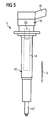
- Fig. 5 illustrates the known per se, basic structure of a piezobetätigten fuel injector 1 for an internal combustion engine.
- the illustrated fuel injector 1 is a diesel injector for use in a reservoir injection system for the internal combustion engine of a motor vehicle.
- the fuel injector 1 includes a fuel injection valve 12 disposed at a lower end of an injector housing 10 elongated in an axial direction A, a piezoactuator 14 for actuating the fuel injection valve 12 disposed in a middle portion of the injector housing 10, and a contact assembly 16 disposed at an upper end of the injector housing 10 electrical connection of the fuel injector 1 via a connector 18 to an injection control unit.
- Essential for the present invention is the realization of the electrical contacting of the piezoelectric actuator 14, ie the Producing an electrical connection between contacts of the piezoelectric actuator 14 and arranged at an axial distance to the contact assembly 16.
- this connecting part 20 is arranged directly above the piezoactuator 14 during assembly of the fuel injector 1.
- Fig. 1 shows the total cylindrical connecting part 20 in AxiallCodesterrorism. It is formed as a plastic molded part comprising a connecting sleeve body 22 made of plastic with therein molded lead wires 24 and also molded, electrically connected to the lead wires spring contacts 26.
- a pair of these wires 24 having a uniform cross section extends parallel to each other in the axial direction A.
- z. B. in adaptation to the further Mulltechniksverlauf in the region of the contact assembly 16, the emerging at the upper end ends of the lead wires 24 have a changing in the course of cross-section and / or mutual distance.
- the emerging at the upper end of the connecting part 20 lead wire ends can be welded, for example, in the region of the contact assembly, z. B. using a contact tongue carrier, as in the aforementioned DE 198 44 743 C1 described. In this case, although a welding process remains during the assembly of the fuel injector. However, this step can then be carried out very comfortably be, especially without a space shortage caused by the injector.
- the connecting part 20 then has, as it were, the function of an "extension" of the contacts of the piezoelectric actuator upwards.
- the conductor wire ends emerging at the upper end of the connecting part 20 can be contacted via a plug connection on the contact module 16.
- connection part 20 at the other end with spring contacts, which are also electrically connected to the molded lines.
- additional spring contacts can z. B. be designed as the intended for contacting the piezoelectric actuator towards spring contacts (eg., For insertion of contact pins of the contact assembly).
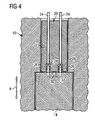
- Each of spring contact 26 is formed by an approximately cylindrical, elongated in the axial direction A cavity for receiving contact pins 28, as shown in the assembled state of FIG. 4 can be seen in the assembled state ,
- one of two positioning pins 30 can also be seen, which are arranged at a lower end face of the connecting part 20 in the axial direction A, diametrically opposite one another (see also FIG. 2).
- the two positioning pins 30 are arranged in this embodiment such that their connection line is orthogonal to a corresponding connecting line between the two spring contacts 26 and thus there are two equivalent mounting positions for the connecting part 20, in which the connecting part 20 introduced from above into the Injektorgeophuse 10 and over the Spring contacts 26 can be brought into electrical contact with the piezoelectric actuator 14.
- the positioning pins 30 are in engagement with positioning pin receptacles 32 provided correspondingly on the upper side of the piezoactuator 14.
- Such recesses 32 can be easily attached be formed of the top facing a top plate, which is usually present anyway at this point of the piezoelectric actuator 14.
- a top plate Corresponding to the arrangement of the spring contacts 26, such a top plate with axial openings or bushings for the passage of the projecting in the axial direction of the contact pins 28 of the piezoelectric actuator 14 may be provided.
- the connecting part 20 has a cylindrical circumferential or lateral surface whose diameter is dimensioned slightly smaller than the diameter of the housing inner wall also in this section of the injector 10, the peripheral surface of the connecting part 20 and corresponding thereto, the housing inner wall the injector 10 are designed such that the desired rotational position of the connecting part 20 is already ensured when inserted into the corresponding housing portion.
- This measure also simplifies the assembly of the fuel injector and can be realized for example by at least one radial bulge of the housing inner wall, which engages in a corresponding recess of an axially extending peripheral surface of the connecting part 20.
- Such an alternative design of the peripheral surface of the connecting part 20 is shown in dashed lines in the plan view of FIG. 3 (indentations 34).
- the spring contacts 26 each have three pairs of such obliquely to the axial direction A provided spring tongues that after the arrival of the contact pins 28 of the piezoelectric actuator 14 in the spring contact receiving spaces these pins 28 are clamped between the individual pairs of spring tongues and prevented from re-emergence.
- the spring contacts 26 thus provide a mechanically and electrically reliable spring clamp connection between the lead wires 24 and the contact pins 28.
- the connecting part 20 provided for electrical contacting of the piezoactuator 14 is inserted from above into the sleeve-shaped injector housing 10 and thus electrically connected to the piezoactuator 14 after installation of the piezoactuator 14 in the injector housing 10. Subsequently, in one or more working steps (eg with a plastic extrusion coating), the contact assembly 16 is formed at the upper end of the fuel injector.
- the connecting part 20 is first attached to the top of the piezoelectric actuator 14 and the thus formed composite is installed in the injector housing 10.
Claims (8)
- Injecteur de carburant pour un moteur à combustion interne, comportant une soupape d'injection de carburant (12), agencée au niveau d'une extrémité inférieure d'un boîtier d'injecteur (10) allongé dans un sens axial (A), un actionneur piézoélectrique (14), monté dans une zone centrale du boîtier d'injecteur (10) et destiné à actionner la soupape d'injection de carburant (12), et un module de contact (16), qui est monté sur une extrémité supérieure du boîtier d'injecteur (10) et est destiné au raccordement électrique de l'injecteur de carburant et qui est relié à des contacts (28) de l'actionneur piézoélectrique (14) pour la mise en contact électrique de l'actionneur piézoélectrique (14) par l'intermédiaire d'un système conducteur s'étendant dans le sens axial entre le module de contact (16) et l'actionneur piézoélectrique (14), le système conducteur étant formé par un élément de liaison (20) inséré dans le sens axial entre le module de contact (16) et l'actionneur piézoélectrique (14), caractérisé en ce que le boîtier d'injecteur (10) comporte, dans la zone de l'élément de liaison (20), une paroi intérieure circulaire fermée, orientée dans le sens axial, laquelle enserre avec un faible jeu l'élément de liaison (20) réalisé avec une surface périphérique orientée dans le sens axial, et en ce que sur l'extrémité de l'élément de liaison (20), orientée vers l'actionneur piézoélectrique (14), sont agencés des contacts flexibles (26) qui sont en appui avec des surfaces de contact flexibles contre les contacts (28) de l'actionneur piézoélectrique (14).
- Injecteur de carburant selon la revendication 1, dans lequel la paroi intérieure de boîtier, orientée dans le sens axial, comporte au moins un creux radial et/ou une bosse radiale, qui est en prise de manière immobile en rotation avec une bosse ou un creux (34) correspondants sur la surface périphérique axiale de l'élément de liaison (20).
- Injecteur de carburant selon l'une quelconque des revendications précédentes, dans lequel une face frontale de l'élément de liaison (20), orientée vers l'actionneur piézoélectrique (14), possède au moins une bosse (30) axiale et/ou un évidement axial qui est en prise de manière immobile en rotation avec une bosse ou un évidement (32) correspondants sur une face frontale de l'actionneur piézoélectrique (14), orientée vers l'élément de liaison (20).
- Injecteur de carburant selon l'une quelconque des revendications précédentes, dans lequel l'actionneur piézoélectrique (14) comporte, sur son extrémité orientée vers l'élément de liaison (20), une plaque supérieure munie de trous débouchants axiaux pour le passage des contacts (28) de l'actionneur piézoélectrique (14), en saillie dans le sens axial.
- Injecteur de carburant selon l'une quelconque des revendications précédentes, dans lequel des conducteurs (24), qui s'étendent entre les deux extrémités axiales de l'élément de liaison (20), sont moulés à l'intérieur de l'élément de liaison (20).
- Injecteur de carburant selon la revendication 5, dans lequel des fils conducteurs (24) s'étendant entre les deux extrémités axiales de l'élément de liaison (20) sont moulés dans l'élément de liaison (20).
- Injecteur de carburant selon la revendication 5 ou 6, dans lequel les contacts flexibles (26) sont moulés dans l'élément de liaison (20).
- Injecteur de carburant selon l'une quelconque des revendications précédentes, dans lequel les contacts flexibles (26) sont réalisés sous forme de contacts de serrage flexibles pour bloquer les contacts (28) en saillie sur l'actionneur piézoélectrique (14).
Applications Claiming Priority (1)
| Application Number | Priority Date | Filing Date | Title |
|---|---|---|---|
| DE200410041170 DE102004041170A1 (de) | 2004-08-25 | 2004-08-25 | Kraftstoffinjektor für eine Brennkraftmaschine sowie Verfahren zur Montage eines derartigen Kraftstoffinjektors |
Publications (3)
| Publication Number | Publication Date |
|---|---|
| EP1630408A1 EP1630408A1 (fr) | 2006-03-01 |
| EP1630408B1 true EP1630408B1 (fr) | 2008-01-02 |
| EP1630408B8 EP1630408B8 (fr) | 2008-05-07 |
Family
ID=34939737
Family Applications (1)
| Application Number | Title | Priority Date | Filing Date |
|---|---|---|---|
| EP20050103817 Not-in-force EP1630408B8 (fr) | 2004-08-25 | 2005-05-09 | Injecteur de carburant pour moteur à combustion interne et procédé de montage de cet injecteur |
Country Status (2)
| Country | Link |
|---|---|
| EP (1) | EP1630408B8 (fr) |
| DE (2) | DE102004041170A1 (fr) |
Families Citing this family (4)
| Publication number | Priority date | Publication date | Assignee | Title |
|---|---|---|---|---|
| DE102005024196B4 (de) * | 2005-05-25 | 2013-05-23 | Continental Automotive Gmbh | Kraftstoffinjektor für eine Brennkraftmaschine sowie Verfahren zur Montage eines derartigen Kraftstoffinjektors |
| DE102007027665A1 (de) * | 2007-06-15 | 2008-12-18 | Robert Bosch Gmbh | Piezoaktormodul mit Kabeldurchführungen und ein Verfahren zu dessen Herstellung |
| DE102010005158A1 (de) * | 2010-01-20 | 2011-04-21 | Continental Automotive Gmbh | Elektrische Anschlussvorrichtung, Aktoreinheit und Einspritzventil |
| DE102013221515A1 (de) * | 2013-10-23 | 2015-04-23 | Continental Automotive Gmbh | Injektor und Kontaktelement für diesen |
Family Cites Families (5)
| Publication number | Priority date | Publication date | Assignee | Title |
|---|---|---|---|---|
| DE3532660A1 (de) * | 1985-09-13 | 1987-03-26 | Atlas Fahrzeugtechnik Gmbh | Kraftstoffeinspritzventil |
| DE3800203C2 (de) * | 1988-01-07 | 1997-08-14 | Atlas Fahrzeugtechnik Gmbh | Kraftstoffeinspritzventil |
| GB2332476B (en) * | 1997-12-19 | 2002-01-16 | Caterpillar Inc | Fuel injector with solenoid and terminal assemblies |
| DE19844743C1 (de) * | 1998-09-29 | 2000-06-08 | Siemens Ag | Kontaktzungenträger zur Abdichtung und Positionierung von Kontaktstiften |
| DE10205909B4 (de) * | 2002-02-13 | 2005-11-10 | Siemens Ag | Dichtungselement für den Piezoaktor eines Kraftstoff-Einspritzventils |
-
2004
- 2004-08-25 DE DE200410041170 patent/DE102004041170A1/de not_active Withdrawn
-
2005
- 2005-05-09 EP EP20050103817 patent/EP1630408B8/fr not_active Not-in-force
- 2005-05-09 DE DE200550002380 patent/DE502005002380D1/de active Active
Also Published As
| Publication number | Publication date |
|---|---|
| EP1630408B8 (fr) | 2008-05-07 |
| DE102004041170A1 (de) | 2006-03-09 |
| EP1630408A1 (fr) | 2006-03-01 |
| DE502005002380D1 (de) | 2008-02-14 |
Similar Documents
| Publication | Publication Date | Title |
|---|---|---|
| DE602005003441T2 (de) | Piezoelektrischer Aktor | |
| EP1558844A1 (fr) | Contact d'actionneur piezo-electrique pour soupape d'injection | |
| WO2006056520A1 (fr) | Pontage electrique dans des injecteurs de carburant | |
| EP0477520B1 (fr) | Bande de contact pour un contact commun d'une pluralité d'aggregats qui sont excités électriquement pour moteurs à moteurs à combustion interne | |
| EP1630408B1 (fr) | Injecteur de carburant pour moteur à combustion interne et procédé de montage de cet injecteur | |
| DE602004012677T2 (de) | Ein Kraftstoffsystem mit integriertem Einspritzventil und Common Rail und Herstellungsvefahren dafür | |
| DE19936534A1 (de) | Kraftstoffhochdruckspeicher | |
| EP2440770B1 (fr) | Soupape d'injection avec unité de transmission | |
| DE3125884A1 (de) | Kraftstoff-einspritzduese fuer brennkraftmaschinen | |
| EP2428672A2 (fr) | Injecteur de carburant | |
| DE102005024196B4 (de) | Kraftstoffinjektor für eine Brennkraftmaschine sowie Verfahren zur Montage eines derartigen Kraftstoffinjektors | |
| DE102004058715B4 (de) | Kraftstoffinjektor für eine Brennkraftmaschine sowie Verfahren zur Herstellung eines Kraftstoffinjektors | |
| WO2004047191A2 (fr) | Metallisation d'actionneur piezo-electrique destinee a une soupape d'injection et procede de fabrication | |
| EP3109911A1 (fr) | Module de piezoacteur, procede de production d'un module de piezoacteur et piezoinjecteur | |
| EP1920477A1 (fr) | Ensemble comprenant un actionneur piezoelectrique | |
| WO2007023041A1 (fr) | Actionneur piezoelectrique pourvu d'un corps de retenue en deux parties | |
| DE102004063293B4 (de) | Kraftstoffinjektor für eine Brennkraftmaschine | |
| EP1712773A1 (fr) | Transmission du courant électrique dans un injecteur de carburant | |
| DE102006036106A1 (de) | Kontaktvorrichtung und Verfahren zum Herstellen einer Kontaktvorrichtung zur elektrischen Kontaktierung eines Piezo-Aktors eines Injektors | |
| DE102004058643B4 (de) | Kraftstoffinjektor für eine Brennkraftmaschine | |
| WO2006058901A1 (fr) | Injecteur de carburant pour moteur a combustion interne | |
| WO2013000695A1 (fr) | Injecteur de carburant | |
| DE102005019806A1 (de) | Einspritzventil für eine Brennkraftmaschine | |
| EP1417406B1 (fr) | Actionneur servant d'unite d'entrainement a un injecteur et procede de fabrication de l'injecteur | |
| DE102004060179B4 (de) | Einspritzventil mit einem verbesserten Anschluss eines Anschlusssteckers |
Legal Events
| Date | Code | Title | Description |
|---|---|---|---|
| PUAI | Public reference made under article 153(3) epc to a published international application that has entered the european phase |
Free format text: ORIGINAL CODE: 0009012 |
|
| AK | Designated contracting states |
Kind code of ref document: A1 Designated state(s): AT BE BG CH CY CZ DE DK EE ES FI FR GB GR HU IE IS IT LI LT LU MC NL PL PT RO SE SI SK TR |
|
| AX | Request for extension of the european patent |
Extension state: AL BA HR LV MK YU |
|
| 17P | Request for examination filed |
Effective date: 20060821 |
|
| AKX | Designation fees paid |
Designated state(s): DE FR GB IT |
|
| 17Q | First examination report despatched |
Effective date: 20070308 |
|
| GRAP | Despatch of communication of intention to grant a patent |
Free format text: ORIGINAL CODE: EPIDOSNIGR1 |
|
| GRAS | Grant fee paid |
Free format text: ORIGINAL CODE: EPIDOSNIGR3 |
|
| GRAA | (expected) grant |
Free format text: ORIGINAL CODE: 0009210 |
|
| RAP1 | Party data changed (applicant data changed or rights of an application transferred) |
Owner name: SIEMENS VDO AUTOMOTIVE AG |
|
| AK | Designated contracting states |
Kind code of ref document: B1 Designated state(s): DE FR GB IT |
|
| REG | Reference to a national code |
Ref country code: GB Ref legal event code: FG4D Free format text: NOT ENGLISH |
|
| REF | Corresponds to: |
Ref document number: 502005002380 Country of ref document: DE Date of ref document: 20080214 Kind code of ref document: P |
|
| RAP2 | Party data changed (patent owner data changed or rights of a patent transferred) |
Owner name: VDO AUTOMOTIVE AG |
|
| RAP2 | Party data changed (patent owner data changed or rights of a patent transferred) |
Owner name: CONTINENTAL AUTOMOTIVE GMBH |
|
| ET | Fr: translation filed | ||
| GBV | Gb: ep patent (uk) treated as always having been void in accordance with gb section 77(7)/1977 [no translation filed] | ||
| PLBE | No opposition filed within time limit |
Free format text: ORIGINAL CODE: 0009261 |
|
| STAA | Information on the status of an ep patent application or granted ep patent |
Free format text: STATUS: NO OPPOSITION FILED WITHIN TIME LIMIT |
|
| 26N | No opposition filed |
Effective date: 20081003 |
|
| PG25 | Lapsed in a contracting state [announced via postgrant information from national office to epo] |
Ref country code: GB Free format text: LAPSE BECAUSE OF FAILURE TO SUBMIT A TRANSLATION OF THE DESCRIPTION OR TO PAY THE FEE WITHIN THE PRESCRIBED TIME-LIMIT Effective date: 20080102 |
|
| PG25 | Lapsed in a contracting state [announced via postgrant information from national office to epo] |
Ref country code: IT Free format text: LAPSE BECAUSE OF FAILURE TO SUBMIT A TRANSLATION OF THE DESCRIPTION OR TO PAY THE FEE WITHIN THE PRESCRIBED TIME-LIMIT Effective date: 20080102 |
|
| REG | Reference to a national code |
Ref country code: FR Ref legal event code: TP Owner name: CONTINENTAL AUTOMOTIVE GMBH, DE Effective date: 20111104 Ref country code: FR Ref legal event code: CD Owner name: CONTINENTAL AUTOMOTIVE GMBH, DE Effective date: 20111104 |
|
| PGFP | Annual fee paid to national office [announced via postgrant information from national office to epo] |
Ref country code: DE Payment date: 20130531 Year of fee payment: 9 |
|
| PGFP | Annual fee paid to national office [announced via postgrant information from national office to epo] |
Ref country code: FR Payment date: 20130603 Year of fee payment: 9 |
|
| REG | Reference to a national code |
Ref country code: DE Ref legal event code: R119 Ref document number: 502005002380 Country of ref document: DE |
|
| REG | Reference to a national code |
Ref country code: DE Ref legal event code: R119 Ref document number: 502005002380 Country of ref document: DE Effective date: 20141202 |
|
| REG | Reference to a national code |
Ref country code: FR Ref legal event code: ST Effective date: 20150130 |
|
| PG25 | Lapsed in a contracting state [announced via postgrant information from national office to epo] |
Ref country code: DE Free format text: LAPSE BECAUSE OF NON-PAYMENT OF DUE FEES Effective date: 20141202 |
|
| PG25 | Lapsed in a contracting state [announced via postgrant information from national office to epo] |
Ref country code: FR Free format text: LAPSE BECAUSE OF NON-PAYMENT OF DUE FEES Effective date: 20140602 |