EP1630408B1 - Fuel injector for an internal combustion engine and method for mounting such an injector - Google Patents
Fuel injector for an internal combustion engine and method for mounting such an injector Download PDFInfo
- Publication number
- EP1630408B1 EP1630408B1 EP20050103817 EP05103817A EP1630408B1 EP 1630408 B1 EP1630408 B1 EP 1630408B1 EP 20050103817 EP20050103817 EP 20050103817 EP 05103817 A EP05103817 A EP 05103817A EP 1630408 B1 EP1630408 B1 EP 1630408B1
- Authority
- EP
- European Patent Office
- Prior art keywords
- connecting part
- piezoactuator
- fuel injector
- contacts
- piezoelectric actuator
- Prior art date
- Legal status (The legal status is an assumption and is not a legal conclusion. Google has not performed a legal analysis and makes no representation as to the accuracy of the status listed.)
- Not-in-force
Links
- 239000000446 fuel Substances 0.000 title claims description 47
- 238000002485 combustion reaction Methods 0.000 title claims description 5
- 238000000034 method Methods 0.000 title description 2
- 238000002347 injection Methods 0.000 claims description 9
- 239000007924 injection Substances 0.000 claims description 9
- 238000007373 indentation Methods 0.000 claims description 7
- 239000002991 molded plastic Substances 0.000 claims 1
- 210000002105 tongue Anatomy 0.000 description 10
- 230000002093 peripheral effect Effects 0.000 description 8
- 238000003466 welding Methods 0.000 description 6
- 238000003780 insertion Methods 0.000 description 5
- 230000037431 insertion Effects 0.000 description 5
- 238000010276 construction Methods 0.000 description 4
- 238000009434 installation Methods 0.000 description 3
- 230000006978 adaptation Effects 0.000 description 2
- 239000004020 conductor Substances 0.000 description 2
- 229910000639 Spring steel Inorganic materials 0.000 description 1
- 239000002131 composite material Substances 0.000 description 1
- 230000001419 dependent effect Effects 0.000 description 1
- 238000011161 development Methods 0.000 description 1
- 230000018109 developmental process Effects 0.000 description 1
- 230000000694 effects Effects 0.000 description 1
- 238000007765 extrusion coating Methods 0.000 description 1
- WABPQHHGFIMREM-UHFFFAOYSA-N lead(0) Chemical compound [Pb] WABPQHHGFIMREM-UHFFFAOYSA-N 0.000 description 1
- 238000004519 manufacturing process Methods 0.000 description 1
- 239000000463 material Substances 0.000 description 1
Images

Classifications
-
- F—MECHANICAL ENGINEERING; LIGHTING; HEATING; WEAPONS; BLASTING
- F02—COMBUSTION ENGINES; HOT-GAS OR COMBUSTION-PRODUCT ENGINE PLANTS
- F02M—SUPPLYING COMBUSTION ENGINES IN GENERAL WITH COMBUSTIBLE MIXTURES OR CONSTITUENTS THEREOF
- F02M51/00—Fuel-injection apparatus characterised by being operated electrically
- F02M51/005—Arrangement of electrical wires and connections, e.g. wire harness, sockets, plugs; Arrangement of electronic control circuits in or on fuel injection apparatus
-
- F—MECHANICAL ENGINEERING; LIGHTING; HEATING; WEAPONS; BLASTING
- F02—COMBUSTION ENGINES; HOT-GAS OR COMBUSTION-PRODUCT ENGINE PLANTS
- F02M—SUPPLYING COMBUSTION ENGINES IN GENERAL WITH COMBUSTIBLE MIXTURES OR CONSTITUENTS THEREOF
- F02M51/00—Fuel-injection apparatus characterised by being operated electrically
- F02M51/06—Injectors peculiar thereto with means directly operating the valve needle
- F02M51/0603—Injectors peculiar thereto with means directly operating the valve needle using piezoelectric or magnetostrictive operating means
-
- F—MECHANICAL ENGINEERING; LIGHTING; HEATING; WEAPONS; BLASTING
- F02—COMBUSTION ENGINES; HOT-GAS OR COMBUSTION-PRODUCT ENGINE PLANTS
- F02M—SUPPLYING COMBUSTION ENGINES IN GENERAL WITH COMBUSTIBLE MIXTURES OR CONSTITUENTS THEREOF
- F02M61/00—Fuel-injectors not provided for in groups F02M39/00 - F02M57/00 or F02M67/00
- F02M61/16—Details not provided for in, or of interest apart from, the apparatus of groups F02M61/02 - F02M61/14
- F02M61/167—Means for compensating clearance or thermal expansion
Definitions
- the present invention relates to a fuel injector for an internal combustion engine according to the preamble of claim 1.
- a fuel injector is for example from the DE 198 44 743 C1 known.
- This publication is concerned with the design of a contact tongue carrier, which is connected by a weld with contacts of a piezoelectric actuator and thus provides a line arrangement for electrical contacting of the piezoelectric actuator.
- the known contact tongue carrier is suitable for direct welding only for fuel injectors, in which the contacts of the piezoelectric actuator viewed in the axial direction extend into the region of the contact assembly (eg plug connector). This is the case, in particular, when the piezoactuator inside the injector housing, viewed in the axial direction, is arranged relatively close to the contact subassembly.
- the known contact tongue carrier is unsuitable for making electrical contact with a piezoelectric actuator provided with relatively short contacts, which is arranged in the axial direction in a more or less large distance from the contact module in the injector housing.
- the effort for welding the contacts of the piezoelectric actuator is disadvantageous in a mounted by means of the contact tongue carrier fuel injector.
- a fuel injector with an electromagnetic actuator is known.
- the electrical contacting of the actuator is carried out by inserting a relatively complex trained connection arrangement (with two approximately conical connecting legs) in two obliquely extending through a Injektorgepatdung connection passages.
- a fuel injector according to the preamble of claim 1 is for example from the EP 0 222 097 A1 , of the DE 38 00 203 A1 and the DE 102 05 909 A1 known.
- the line arrangement is formed by a connecting part inserted axially between the contact module and the piezoactuator, at whose end facing the piezoelectric actuator spring contacts are arranged, which abut against the contacts of the piezoactuator with contact surfaces which can be deflected.
- the electrical contacting of the piezoelectric actuator is thus considerably simplified. In particular, it is not necessary to weld the contacts of the piezoelectric actuator with the line arrangement.
- the invention allows a fuel injector, in which the electrical contacting of a piezo actuator already mounted in the injector in a very simple manner by inserting a prefabricated unit (connecting part) takes place during assembly.
- the sleeve-shaped injector housing in the region of the connecting part has an annularly closed, axially extending housing inner wall which encloses the connecting part formed with an axially extending peripheral surface with slight play.
- This structural adaptation of the connecting part to the housing inner wall results in a simple insertion of the connecting part and at the same time a certain guidance of the connecting part during insertion.
- the housing inner wall provided in the region of the connecting part and the peripheral surface of the connecting part guided therefrom can, for example, be substantially cylindrical.
- other cross-sectional shapes of these mutually facing surfaces are conceivable as long as the design makes it possible for the connecting part to be pushed into this housing section in the axial direction.
- conical surfaces are also conceivable in principle.
- connection part provided according to the invention can advantageously be adapted to the distance of the relevant injector design.
- spring contacts eg made of spring steel
- This vibration resistance is often superior in practice to the corresponding strength of a welded joint.
- the spring contacts of the connecting part can reliably reach the contacts of the piezoelectric actuator for engagement or engaged.
- automated assembly steps can be simplified by such an anti-rotation device.
- the line ends at the other end of the connection part should be considered, in particular, at the position which is well defined by a rotation lock. The electrical continuity occurring there can then be automated without any problems with regard to the angular position of the connecting part.
- the axially extending housing inner wall has at least one radial indentation and / or indentation, which engages in a rotationally locking manner in engagement with a corresponding indentation or indentation of the axially extending peripheral surface of the connecting part is.
- an end face of the connecting part facing the piezoactuator has at least one axial sublime and / or recess which engages in a rotationally locking manner in engagement with a corresponding recess or grandeur of an end face of the piezoactuator facing the connecting part.
- the piezoelectric actuator at its end facing the connecting part to a so-called head plate, which is provided with axial passages, so that axially projecting contacts of the piezoelectric actuator can pass through these passages.
- a per se known top plate may have at least one of the above-mentioned axial recesses or sublime in order to provide an anti-rotation device for the connecting part in the context of the invention.
- connecting part A simple production of the connecting part is obtained, for example, if this is designed as a plastic molded part, wherein for the realization of the line arrangement between the two axial ends of the connecting part extending lines and / or the spring contacts can be formed in such a connecting part in a simple manner.
- lead wires electrically connected (eg, welded) to spring contact units may be molded into the plastic material.
- the electrical connection between the spring contacts of the connecting part and the contacts of the piezoelectric actuator - in a sense "automatically” - simply by inserting the connecting part in the axial direction in the relevant Injektorgepurabites.
- the contacts of the piezoelectric actuator as axially projecting from the piezoelectric actuator contacts, in particular contact pins are formed, which come when inserting the connecting part with its spring contacts to the system or in engagement.
- the spring contacts may, for example, have contact surfaces which extend substantially orthogonally to the axial direction and spring down in the axial direction, which run against the end faces of the contacts of the piezoactuator, which are designed, for example, as axially projecting pins, during assembly of the connection part.
- axially projecting contact pins of the piezoelectric actuator at their peripheral surfaces with suitably formed (radially resilient) spring contact surfaces come into contact.
- the spring contacts are designed as spring terminal contacts for clamping the contacts projecting from the piezoelectric actuator.
- the contact pins are each loaded on their peripheral surface of at least two sides radially by spring contact surfaces of a spring contact.
- Such a contact pin radially contacting contact surfaces can be achieved, for example, by extending obliquely to the axial spring contact tongues, which are displaced in the assembly of the connecting part by the axially projecting pins of the piezo actuator slightly in the radial direction and then radially load the relevant contact pin due to their spring action.
- Such spring contact tongues can be distributed individually in the circumferential direction and / or annularly closed (in total, for example, conical). Due to the oblique course of (for example, compared to the transverse extent of the pins thin) spring contact tongues it is possible by such an inclination to achieve a "barb effect" of the spring terminal contact, through which a once inserted into the spring terminal contact pin of the piezoelectric actuator is reliably engaged.
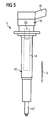
- Fig. 5 illustrates the known per se, basic structure of a piezobetätigten fuel injector 1 for an internal combustion engine.
- the illustrated fuel injector 1 is a diesel injector for use in a reservoir injection system for the internal combustion engine of a motor vehicle.
- the fuel injector 1 includes a fuel injection valve 12 disposed at a lower end of an injector housing 10 elongated in an axial direction A, a piezoactuator 14 for actuating the fuel injection valve 12 disposed in a middle portion of the injector housing 10, and a contact assembly 16 disposed at an upper end of the injector housing 10 electrical connection of the fuel injector 1 via a connector 18 to an injection control unit.
- Essential for the present invention is the realization of the electrical contacting of the piezoelectric actuator 14, ie the Producing an electrical connection between contacts of the piezoelectric actuator 14 and arranged at an axial distance to the contact assembly 16.
- this connecting part 20 is arranged directly above the piezoactuator 14 during assembly of the fuel injector 1.
- Fig. 1 shows the total cylindrical connecting part 20 in AxiallCodesterrorism. It is formed as a plastic molded part comprising a connecting sleeve body 22 made of plastic with therein molded lead wires 24 and also molded, electrically connected to the lead wires spring contacts 26.
- a pair of these wires 24 having a uniform cross section extends parallel to each other in the axial direction A.
- z. B. in adaptation to the further Mulltechniksverlauf in the region of the contact assembly 16, the emerging at the upper end ends of the lead wires 24 have a changing in the course of cross-section and / or mutual distance.
- the emerging at the upper end of the connecting part 20 lead wire ends can be welded, for example, in the region of the contact assembly, z. B. using a contact tongue carrier, as in the aforementioned DE 198 44 743 C1 described. In this case, although a welding process remains during the assembly of the fuel injector. However, this step can then be carried out very comfortably be, especially without a space shortage caused by the injector.
- the connecting part 20 then has, as it were, the function of an "extension" of the contacts of the piezoelectric actuator upwards.
- the conductor wire ends emerging at the upper end of the connecting part 20 can be contacted via a plug connection on the contact module 16.
- connection part 20 at the other end with spring contacts, which are also electrically connected to the molded lines.
- additional spring contacts can z. B. be designed as the intended for contacting the piezoelectric actuator towards spring contacts (eg., For insertion of contact pins of the contact assembly).
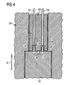
- Each of spring contact 26 is formed by an approximately cylindrical, elongated in the axial direction A cavity for receiving contact pins 28, as shown in the assembled state of FIG. 4 can be seen in the assembled state ,
- one of two positioning pins 30 can also be seen, which are arranged at a lower end face of the connecting part 20 in the axial direction A, diametrically opposite one another (see also FIG. 2).
- the two positioning pins 30 are arranged in this embodiment such that their connection line is orthogonal to a corresponding connecting line between the two spring contacts 26 and thus there are two equivalent mounting positions for the connecting part 20, in which the connecting part 20 introduced from above into the Injektorgeophuse 10 and over the Spring contacts 26 can be brought into electrical contact with the piezoelectric actuator 14.
- the positioning pins 30 are in engagement with positioning pin receptacles 32 provided correspondingly on the upper side of the piezoactuator 14.
- Such recesses 32 can be easily attached be formed of the top facing a top plate, which is usually present anyway at this point of the piezoelectric actuator 14.
- a top plate Corresponding to the arrangement of the spring contacts 26, such a top plate with axial openings or bushings for the passage of the projecting in the axial direction of the contact pins 28 of the piezoelectric actuator 14 may be provided.
- the connecting part 20 has a cylindrical circumferential or lateral surface whose diameter is dimensioned slightly smaller than the diameter of the housing inner wall also in this section of the injector 10, the peripheral surface of the connecting part 20 and corresponding thereto, the housing inner wall the injector 10 are designed such that the desired rotational position of the connecting part 20 is already ensured when inserted into the corresponding housing portion.
- This measure also simplifies the assembly of the fuel injector and can be realized for example by at least one radial bulge of the housing inner wall, which engages in a corresponding recess of an axially extending peripheral surface of the connecting part 20.
- Such an alternative design of the peripheral surface of the connecting part 20 is shown in dashed lines in the plan view of FIG. 3 (indentations 34).
- the spring contacts 26 each have three pairs of such obliquely to the axial direction A provided spring tongues that after the arrival of the contact pins 28 of the piezoelectric actuator 14 in the spring contact receiving spaces these pins 28 are clamped between the individual pairs of spring tongues and prevented from re-emergence.
- the spring contacts 26 thus provide a mechanically and electrically reliable spring clamp connection between the lead wires 24 and the contact pins 28.
- the connecting part 20 provided for electrical contacting of the piezoactuator 14 is inserted from above into the sleeve-shaped injector housing 10 and thus electrically connected to the piezoactuator 14 after installation of the piezoactuator 14 in the injector housing 10. Subsequently, in one or more working steps (eg with a plastic extrusion coating), the contact assembly 16 is formed at the upper end of the fuel injector.
- the connecting part 20 is first attached to the top of the piezoelectric actuator 14 and the thus formed composite is installed in the injector housing 10.
Description
Die vorliegende Erfindung betrifft einen Kraftstoffinjektor für eine Brennkraftmaschine nach dem Oberbegriff des Anspruchs 1.The present invention relates to a fuel injector for an internal combustion engine according to the preamble of claim 1.
Ein Kraftstoffinjektor ist beispielsweise aus der
Der bekannte Kontaktzungenträger ist zum unmittelbaren Anschweißen lediglich für Kraftstoffinjektoren geeignet, bei welchen sich die Kontakte des Piezoaktors in Axialrichtung betrachtet bis hin in den Bereich der Kontaktbaugruppe (z. B. Steckverbinder) erstrecken. Dies ist insbesondere dann der Fall, wenn der Piezoaktor innerhalb des Injektorgehäuses in Axialrichtung betrachtet relativ nahe der Kontaktbaugruppe angeordnet ist. Ungeeignet ist der bekannte Kontaktzungenträger jedoch zur elektrischen Kontaktierung eines mit relativ kurzen Kontakten versehenen Piezoaktors, der in Axialrichtung betrachtet in einem mehr oder weniger großen Abstand zur Kontaktbaugruppe im Injektorgehäuse angeordnet ist. Außerdem ist bei einem mittels des Kontaktzungenträgers montierten Kraftstoffinjektor der Aufwand zum Verschweißen der Kontakte des Piezoaktors nachteilig.The known contact tongue carrier is suitable for direct welding only for fuel injectors, in which the contacts of the piezoelectric actuator viewed in the axial direction extend into the region of the contact assembly (eg plug connector). This is the case, in particular, when the piezoactuator inside the injector housing, viewed in the axial direction, is arranged relatively close to the contact subassembly. However, the known contact tongue carrier is unsuitable for making electrical contact with a piezoelectric actuator provided with relatively short contacts, which is arranged in the axial direction in a more or less large distance from the contact module in the injector housing. In addition, the effort for welding the contacts of the piezoelectric actuator is disadvantageous in a mounted by means of the contact tongue carrier fuel injector.
Gemäß eines auf internen betrieblichen Kenntnissen der Anmelderin beruhenden Stands der Technik ist vorgesehen, vergleichsweise kurze Kontakte des Piezoaktors vor einem Einschieben des Piezoaktors in das Injektorgehäuse durch Anschweißen von Leitungsdrähten in Axialrichtung zu verlängern. Auch hierbei entsteht ein bei der Montage des Kraftstoffinjektors nicht zu vernachlässigender Aufwand für eine zusätzliche Verschweißung.According to a prior art based on internal operational knowledge of the Applicant, it is provided comparatively To extend short contacts of the piezoelectric actuator before inserting the piezoelectric actuator in the injector by welding conductor wires in the axial direction. Here, too, arises during the installation of the fuel injector not negligible effort for additional welding.
Aus der
Ein Kraftstoffinjektor nach dem Oberbegriff des Anspruchs 1 ist beispielsweise aus der
Bei dem aus den Veröffentlichungen
Bei dem aus der
Es ist eine Aufgabe der vorliegenden Erfindung, die elektrische Kontaktierung eines Piezoaktors in einem Kraftstoffinjektor zu vereinfachen.It is an object of the present invention to simplify the electrical contacting of a piezoactuator in a fuel injector.
Diese Aufgabe wird gelöst durch einen Kraftstoffinjektor nach Anspruch 1. Die abhängigen Ansprüche betreffen vorteilhafte Weiterbildungen der Erfindung.This object is achieved by a fuel injector according to claim 1. The dependent claims relate to advantageous developments of the invention.
Bei dem erfindungsgemäßen Kraftstoffinjektor ist vorgesehen, dass die Leitungsanordnung von einem axial zwischen der Kontaktbaugruppe und dem Piezoaktor eingefügten Verbindungsteil ausgebildet ist, an dessen dem Piezoaktor zugewandten Ende Federkontakte angeordnet sind, die mit einfederbaren Kontaktflächen an den Kontakten des Piezoaktors anliegen.In the case of the fuel injector according to the invention, it is provided that the line arrangement is formed by a connecting part inserted axially between the contact module and the piezoactuator, at whose end facing the piezoelectric actuator spring contacts are arranged, which abut against the contacts of the piezoactuator with contact surfaces which can be deflected.
Die elektrische Kontaktierung des Piezoaktors ist damit erheblich vereinfacht. Insbesondere ist es nicht erforderlich, die Kontakte des Piezoaktors mit der Leitungsanordnung zu verschweißen.The electrical contacting of the piezoelectric actuator is thus considerably simplified. In particular, it is not necessary to weld the contacts of the piezoelectric actuator with the line arrangement.
Darüber hinaus ermöglicht die Erfindung einen Kraftstoffinjektor, bei welchem im Rahmen der Montage die elektrische Kontaktierung eines bereits im Injektorgehäuse montierten Piezoaktors in sehr einfacher Weise durch Einfügen einer vorgefertigten Einheit (Verbindungsteil) erfolgt.In addition, the invention allows a fuel injector, in which the electrical contacting of a piezo actuator already mounted in the injector in a very simple manner by inserting a prefabricated unit (connecting part) takes place during assembly.
Gemäß der Erfindung ist ferner vorgesehen, dass das hülsenförmige Injektorgehäuse im Bereich des Verbindungsteils eine ringförmig geschlossene, axial sich erstreckende Gehäuseinnenwand aufweist, welche das mit einer axial sich erstreckenden Umfangsfläche ausgebildete Verbindungsteil mit geringfügigem Spiel umschließt. Durch diese konstruktive Anpassung des Verbindungsteils an die Gehäuseinnenwand ergibt sich eine einfache Einschiebbarkeit des Verbindungsteils und gleichzeitig eine gewisse Führung des Verbindungsteils beim Einschieben. Die im Bereich des Verbindungsteils vorgesehene Gehäuseinnenwand sowie die davon geführte Umfangsfläche des Verbindungsteils können beispielsweise im wesentlichen zylindrisch ausgebildet sein. Es sind jedoch auch andere Querschnittsformen dieser einander zugewandten Flächen denkbar, solange die Gestaltung es ermöglicht, dass das Verbindungsteil in Axialrichtung in diesen Gehäuseabschnitt eingeschoben werden kann. In dieser Hinsicht sind auch konische Flächen prinzipiell denkbar.According to the invention, it is further provided that the sleeve-shaped injector housing in the region of the connecting part has an annularly closed, axially extending housing inner wall which encloses the connecting part formed with an axially extending peripheral surface with slight play. This structural adaptation of the connecting part to the housing inner wall results in a simple insertion of the connecting part and at the same time a certain guidance of the connecting part during insertion. The housing inner wall provided in the region of the connecting part and the peripheral surface of the connecting part guided therefrom can, for example, be substantially cylindrical. However, other cross-sectional shapes of these mutually facing surfaces are conceivable as long as the design makes it possible for the connecting part to be pushed into this housing section in the axial direction. In this regard, conical surfaces are also conceivable in principle.
Diese vereinfachte Montage ist insbesondere für Konstruktionen von Vorteil, bei welchen im eingebauten Zustand des Piezoaktors dessen Kontakte vergleichsweise schwer zugänglich sind. Dies kann beispielsweise dann der Fall sein, wenn in Axialrichtung betrachtet ein vergleichsweise großer Abstand zwischen dem Piezoaktor und der Kontaktbaugruppe durch die Leitungsanordnung bzw. das Verbindungsteil zu überbrücken ist. Das gemäß der Erfindung hierfür vorgesehene Verbindungsteil kann vorteilhaft an den Abstand der betreffenden Injektorkonstruktion angepasst werden.This simplified assembly is particularly advantageous for constructions in which the contacts are relatively difficult to access in the installed state of the piezoelectric actuator. This can be the case, for example, when viewed in the axial direction to bridge a comparatively large distance between the piezoelectric actuator and the contact assembly through the line assembly or the connecting part is. The connection part provided according to the invention can advantageously be adapted to the distance of the relevant injector design.
Durch die Verwendung von Federkontakten (z. B. aus Federstahl) ergibt sich eine verbesserte Vibrationsfestigkeit der elektrischen Kontaktierung. Diese Vibrationsfestigkeit ist in der Praxis der entsprechenden Festigkeit einer Schweißverbindung oftmals überlegen. Bislang bei der oben erwähnten Verlängerung der Kontakte des Piezoaktors durch Anschweißen von Verlängerungsdrähten abhängig von der Konstruktion notwendige Maßnahmen zum Ausgleich von Längenänderungen (z. B. thermisch bedingt) und/oder Maßnahmen zur Zug- und Druckentlastung der Schweißnähte können bei dem erfindungsgemäßen Kraftstoffinjektor vorteilhaft entfallen.The use of spring contacts (eg made of spring steel) results in an improved vibration resistance of the electrical contact. This vibration resistance is often superior in practice to the corresponding strength of a welded joint. So far, in the above-mentioned extension of the contacts of the piezoelectric actuator by welding extension wires depending on the construction necessary measures to compensate for changes in length (eg thermally induced) and / or measures for tension and pressure relief of the welds can advantageously be omitted in the fuel injector according to the invention ,
Es ist von Vorteil, Maßnahmen zur Verdrehsicherung betreffend das in das Injektorgehäuse einzufügende Verbindungsteil vorzusehen. Beispielsweise können dann die Federkontakte des Verbindungsteils zuverlässig an den Kontakten des Piezoaktors zur Anlage bzw. in Eingriff gelangen. Ferner können durch eine solche Verdrehsicherung automatisierte Montageschritte vereinfacht werden. Hierbei ist insbesondere an die durch eine Verdrehsicherung gut definierte Lage auch der Leitungsenden am anderen Ende des Verbindungsteils (zur Kontaktbaugruppe hin) zu denken. Die dort erfolgende elektrische Weiterverbindung kann dann ohne Probleme hinsichtlich der Winkelstellung des Verbindungsteils automatisiert erfolgen.It is advantageous to provide measures for preventing rotation in relation to the connecting part to be inserted into the injector housing. For example, then the spring contacts of the connecting part can reliably reach the contacts of the piezoelectric actuator for engagement or engaged. Furthermore, automated assembly steps can be simplified by such an anti-rotation device. In this case, the line ends at the other end of the connection part (towards the contact module) should be considered, in particular, at the position which is well defined by a rotation lock. The electrical continuity occurring there can then be automated without any problems with regard to the angular position of the connecting part.
In einer Ausführungsform ist daher vorgesehen, dass die axial sich erstreckende Gehäuseinnenwand wenigstens eine radiale Einbuchtung und/oder Ausbuchtung aufweist, die verdrehsichernd im Eingriff mit einer korrespondierenden Ausbuchtung bzw. Einbuchtung der axial sich erstreckenden Umfangsfläche des Verbindungsteils steht. Alternativ oder zusätzlich kann vorgesehen sein, dass eine dem Piezoaktor zugewandte Stirnfläche des Verbindungsteils wenigstens eine axiale Erhabenheit und/oder Aussparung aufweist, die verdrehsichernd im Eingriff mit einer korrespondierenden Aussparung bzw. Erhabenheit einer dem Verbindungsteil zugewandten Stirnfläche des Piezoaktors steht.In one embodiment, it is therefore provided that the axially extending housing inner wall has at least one radial indentation and / or indentation, which engages in a rotationally locking manner in engagement with a corresponding indentation or indentation of the axially extending peripheral surface of the connecting part is. Alternatively or additionally, it may be provided that an end face of the connecting part facing the piezoactuator has at least one axial sublime and / or recess which engages in a rotationally locking manner in engagement with a corresponding recess or grandeur of an end face of the piezoactuator facing the connecting part.
Bevorzugt weist der Piezoaktor an seinem dem Verbindungsteil zugewandten Ende eine so genannte Kopfplatte auf, die mit axialen Durchführungen versehen ist, so dass in Axialrichtung abstehende Kontakte des Piezoaktors durch diese Durchführungen durchtreten können. Eine solche an sich bekannte Kopfplatte kann im Rahmen der Erfindung wenigstens eine der oben erwähnten axialen Aussparungen bzw. Erhabenheiten aufweisen, um eine Verdrehsicherung für das Verbindungsteil vorzusehen.Preferably, the piezoelectric actuator at its end facing the connecting part to a so-called head plate, which is provided with axial passages, so that axially projecting contacts of the piezoelectric actuator can pass through these passages. Such a per se known top plate may have at least one of the above-mentioned axial recesses or sublime in order to provide an anti-rotation device for the connecting part in the context of the invention.
Eine einfache Herstellung des Verbindungsteils ergibt sich, beispielsweise dann, wenn dieses als Kunststoffformteil ausgebildet ist, wobei zur Realisierung der Leitungsanordnung zwischen den beiden axialen Enden des Verbindungsteils sich erstreckende Leitungen und/oder die Federkontakte in einem solchen Verbindungsteil in einfacher Weise eingeformt sein können. Beispielsweise können mit Federkontakteinheiten elektrisch verbundene (z. B. verschweißte) Leitungsdrähte in das Kunststoffmaterial eingeformt werden.A simple production of the connecting part is obtained, for example, if this is designed as a plastic molded part, wherein for the realization of the line arrangement between the two axial ends of the connecting part extending lines and / or the spring contacts can be formed in such a connecting part in a simple manner. For example, lead wires electrically connected (eg, welded) to spring contact units may be molded into the plastic material.
Bevorzugt erfolgt die elektrische Verbindung zwischen den Federkontakten des Verbindungsteils und den Kontakten des Piezoaktors - gewissermaßen "automatisch" - einfach durch Einschieben des Verbindungsteils in Axialrichtung in den betreffenden Injektorgehäuseabschnitt. Hierzu ist es zweckmäßig, wenn die Kontakte des Piezoaktors als axial vom Piezoaktor abstehende Kontakte, insbesondere Kontaktstifte ausgebildet sind, welche beim Einfügen des Verbindungsteils mit dessen Federkontakten zur Anlage bzw. in Eingriff gelangen.Preferably, the electrical connection between the spring contacts of the connecting part and the contacts of the piezoelectric actuator - in a sense "automatically" - simply by inserting the connecting part in the axial direction in the relevant Injektorgehäuseabschnitt. For this it is expedient when the contacts of the piezoelectric actuator as axially projecting from the piezoelectric actuator contacts, in particular contact pins are formed, which come when inserting the connecting part with its spring contacts to the system or in engagement.
Die Federkontakte können beispielsweise im wesentlichen orthogonal zur Axialrichtung sich erstreckende und in Axialrichtung einfedernde Kontaktflächen aufweisen, die bei der Montage des Verbindungsteils gegen die Stirnseiten der beispielsweise als axial abstehende Stifte ausgebildeten Kontakte des Piezoaktors laufen. Alternativ oder zusätzlich können solche axial abstehenden Kontaktstifte des Piezoaktors an deren Umfangsflächen mit geeignet ausgebildeten (radial federnden) Federkontaktflächen in Verbindung treten.The spring contacts may, for example, have contact surfaces which extend substantially orthogonally to the axial direction and spring down in the axial direction, which run against the end faces of the contacts of the piezoactuator, which are designed, for example, as axially projecting pins, during assembly of the connection part. Alternatively or additionally, such axially projecting contact pins of the piezoelectric actuator at their peripheral surfaces with suitably formed (radially resilient) spring contact surfaces come into contact.
In einer bevorzugten Ausführungsform sind die Federkontakte als Federklemmkontakte zum Einklemmen der vom Piezoaktor abstehenden Kontakte ausgebildet. Für axial vom Piezoaktor abstehende Kontaktstifte eines Piezoaktors bedeutet dies, dass die Kontaktstifte jeweils von an ihrer Umfangsfläche von wenigstens zwei Seiten her radial durch Federkontaktflächen eines Federkontakts belastet werden. Solche einen Kontaktstift radial kontaktierenden Kontaktflächen lassen sich beispielsweise durch derart schräg zur Axialrichtung verlaufende Federkontaktzungen erreichen, die bei der Montage des Verbindungsteils durch die axial vorstehenden Kontaktstifte des Piezoaktors etwas in Radialrichtung verdrängt werden und aufgrund ihrer Federwirkung den betreffenden Kontaktstift dann radial belasten. Solche Federkontaktzungen können einzeln in Umfangsrichtung verteilt angeordnet werden und/oder ringförmig geschlossen (insgesamt z. B. konisch) ausgebildet sein. Durch den schrägen Verlauf von (z. B. im Vergleich zur Querausdehnung der Kontaktstifte dünnen) Federkontaktzungen ist es durch eine solche Schrägstellung möglich, einen "Widerhakeneffekt" des Federklemmkontaktes zu erzielen, durch welchen ein einmal in den Federklemmkontakt eingeschobener Kontaktstift des Piezoaktors zuverlässig im Eingriff gehalten wird.In a preferred embodiment, the spring contacts are designed as spring terminal contacts for clamping the contacts projecting from the piezoelectric actuator. For axially projecting from the piezoelectric actuator pins of a piezoelectric actuator, this means that the contact pins are each loaded on their peripheral surface of at least two sides radially by spring contact surfaces of a spring contact. Such a contact pin radially contacting contact surfaces can be achieved, for example, by extending obliquely to the axial spring contact tongues, which are displaced in the assembly of the connecting part by the axially projecting pins of the piezo actuator slightly in the radial direction and then radially load the relevant contact pin due to their spring action. Such spring contact tongues can be distributed individually in the circumferential direction and / or annularly closed (in total, for example, conical). Due to the oblique course of (for example, compared to the transverse extent of the pins thin) spring contact tongues it is possible by such an inclination to achieve a "barb effect" of the spring terminal contact, through which a once inserted into the spring terminal contact pin of the piezoelectric actuator is reliably engaged.
Die Erfindung wird nachfolgend anhand eines Ausführungsbeispiels mit Bezug auf die beigefügten Zeichnungen näher beschrieben. Es stellen dar:
- Fig. 1
- ist ein Axiallängsschnitt eines zylindrischen Verbindungsteils zur Kontaktierung eines Piezoaktors,
- Fig. 2
- ist eine Seitenansicht des Verbindungsteils,
- Fig. 3
- ist eine Draufsicht des Verbindungsteils,
- Fig. 4
- ist eine Axiallängsschnittansicht ähnlich der Fig. 1, die das Verbindungsteil in dessen Installationsumgebung in einem Injektorgehäuse zeigt, und
- Fig. 5
- ist eine Seitenansicht eines Kraftstoffinjektors mit einem Piezoaktor, der unter Verwendung des Verbindungsteils zur elektrischen Kontaktierung des Piezoaktors montiert wurde.
- Fig. 1
- is an axial longitudinal section of a cylindrical connecting part for contacting a piezoelectric actuator,
- Fig. 2
- is a side view of the connecting part,
- Fig. 3
- is a plan view of the connecting part,
- Fig. 4
- is an axial longitudinal sectional view similar to Figure 1, showing the connecting part in its installation environment in an injector, and
- Fig. 5
- is a side view of a fuel injector with a piezoelectric actuator, which has been mounted using the connection part for electrically contacting the piezoelectric actuator.
Fig. 5 veranschaulicht den an sich bekannten, prinzipiellen Aufbau eines piezobetätigten Kraftstoffinjektors 1 für eine Brennkraftmaschine. Bei dem dargestellten Kraftstoffinjektor 1 handelt es sich um einen Dieselinjektor zur Verwendung in einem Speichereinspritzsystem für die Brennkraftmaschine eines Kraftfahrzeugs.Fig. 5 illustrates the known per se, basic structure of a piezobetätigten fuel injector 1 for an internal combustion engine. The illustrated fuel injector 1 is a diesel injector for use in a reservoir injection system for the internal combustion engine of a motor vehicle.
Der Kraftstoffinjektor 1 umfasst ein an einem unteren Ende eines in einer Axialrichtung A langgestreckten Injektorgehäuses 10 angeordnetes Kraftstoffeinspritzventil 12, einen in einem mittleren Bereich des Injektorgehäuses 10 angeordneten Piezoaktor 14 zur Betätigung des Kraftstoffeinspritzventils 12 und eine an einem oberen Ende des Injektorgehäuses 10 angeordnete Kontaktbaugruppe 16 zum elektrischen Anschluss des Kraftstoffinjektors 1 über einen Steckverbinder 18 an eine Einspritzsteuereinheit.The fuel injector 1 includes a
In an sich bekannter Weise sind am oberen Ende des Injektorgehäuses 10 Anschlüsse für eine Hochdruck-Kraftstoffzufuhr aus einem Kraftstoff-Druckspeicher ("common rail") sowie eine Kraftstoffabfuhr (Leckageleitung) vorgesehen. Diese Komponenten sind für das Verständnis der Erfindung nicht wesentlich und daher in der Darstellung von Fig. 5 weggelassen. Dasselbe gilt für Details des Piezoaktors 14, dessen Wirkverbindung zum Einspritzventil 12 sowie die konkrete Gestaltung dieses Einspritzventils 12. Möglichkeiten zur Gestaltung des Piezoaktors 14 sowie des damit in Wirkverbindung stehenden Kraftstoffeinspritzventils 12 (z. B. hydraulisches Servoventil) sind dem Fachmann wohlbekannt und bedürfen daher keiner näheren Erläuterung. Lediglich beispielhaft sei im Hinblick auf die Gestaltung des Kraftstoffinjektors insgesamt auf die
Für die vorliegende Erfindung wesentlich ist die Realisierung der elektrischen Kontaktierung des Piezoaktors 14, d.h. die Herstellung einer elektrischen Verbindung zwischen Kontakten des Piezoaktors 14 und der im axialen Abstand dazu angeordneten Kontaktbaugruppe 16. Diese elektrische Kontaktierung des Piezoaktors 14 erfolgt über eine axial zwischen der Kontaktbaugruppe 16 und dem Piezoaktor 14 sich erstreckende Leitungsanordnung, die bei dem Kraftstoffinjektor 1 von einem axial zwischen der Kontaktbaugruppe 16 und dem Piezoaktor 14 eingefügten Verbindungsteil 20 ausgebildet ist. Zur Herstellung einer elektrischen Verbindung zwischen dem Verbindungteil 20 und dem Piezoaktor 14 wird dieses Verbindungsteil 20 bei der Montage des Kraftstoffinjektors 1 unmittelbar über dem Piezoaktor 14 angeordnet.Essential for the present invention is the realization of the electrical contacting of the
Fig. 1 zeigt das insgesamt zylindrische Verbindungsteil 20 im Axiallängsschnitt. Es ist als Kunststoffformteil umfassend einen Verbindungshülsenkorpus 22 aus Kunststoff mit darin eingeformten Leitungsdrähten 24 und ebenfalls eingeformten, an den Leitungsdrähten elektrisch angeschlossenen Federkontakten 26 ausgebildet. Im dargestellten Ausführungsbeispiel erstreckt sich ein Paar von diesen Leitungsdrähten 24 mit einheitlichem Querschnitt parallel zueinander in Axialrichtung A. Abweichend von diesem Beispiel ist es jedoch denkbar, dass z. B. in Anpassung an den weiteren Kontaktierungsverlauf im Bereich der Kontaktbaugruppe 16 die am oberen Ende austretenden Enden der Leitungsdrähte 24 einen im Verlauf sich ändernden Querschnitt und/oder gegenseitigen Abstand besitzen. Die am oberen Ende des Verbindungsteils 20 austretenden Leitungsdrahtenden können beispielsweise im Bereich der Kontaktbaugruppe verschweißt werden, z. B. unter Verwendung eines Kontaktzungenträgers, wie in der eingangs erwähnten
Mit den eingeformten Leitungsdrähten 24 elektrisch verbunden ist jeweils einer der als Einsteckaufnahmen ausgebildeten Federkontakte 26. Jeder Federkontakt 26 ist gebildet von einem etwa zylindrischen, in Axialrichtung A langgestreckten Hohlraum zur Aufnahme von Kontaktstiften 28, wie aus der Darstellung im montierten Zustand nach Fig. 4 ersichtlich.Each of
In Fig. 1 ist ferner einer von zwei Positionierstiften 30 zu erkennen, die an einer unteren Stirnseite des Verbindungsteils 20 in Axialrichtung A abstehend, diametral einander gegenüberliegend angeordnet sind (vgl. auch Fig. 2).In FIG. 1, one of two
Wie es aus Fig. 2 ersichtlich ist, sind die beiden Positionierstifte 30 bei diesem Ausführungsbeispiel derart angeordnet, dass deren Verbindungslinie orthogonal zu einer entsprechenden Verbindungslinie zwischen den beiden Federkontakten 26 ist und es somit zwei gleichwertige Montagestellungen für das Verbindungsteil 20 gibt, in denen das Verbindungsteil 20 von oben in das Injektorgehäuse 10 eingeführt und über die Federkontakte 26 in elektrischen Kontakt mit dem Piezoaktor 14 gebracht werden kann. Im montierten Zustand des Kraftstoffinjektors 1 (Fig. 4) stehen die Positionierstifte 30 im Eingriff mit korrespondierend an der Oberseite des Piezoaktors 14 vorgesehenen Positionierstiftaufnahmen 32. Derartige Aussparungen 32 (oder auch Erhabenheiten zum Eingriff in korrespondierende Aussparungen des Verbindungsteils 20) können in einfacher Weise an der nach oben gewandten Stirnseite einer Kopfplatte ausgebildet sein, die an dieser Stelle des Piezoaktors 14 üblicherweise ohnehin vorhanden ist. Korrespondierend zur Anordnung der Federkontakte 26 kann eine solche Kopfplatte mit axialen Öffnungen bzw. Durchführungen zum Durchtritt der in Axialrichtung abstehenden Kontaktstifte 28 des Piezoaktors 14 versehen sein.As is apparent from Fig. 2, the two
Abweichend vom dargestellten Ausführungsbeispiel, bei welchem das Verbindungsteil 20 eine zylindrische Umfangs- bzw. Mantelfläche besitzt, deren Durchmesser geringfügig kleiner bemessen ist als der Durchmesser der in diesem Abschnitt des Injektorgehäuses 10 ebenfalls zylindrischen Gehäuseinnenwand, könnten die Umfangsfläche des Verbindungsteils 20 sowie korrespondierend hierzu die Gehäuseinnenwand des Injektorgehäuses 10 derart gestaltet werden, dass die gewünschte Drehstellung des Verbindungsteils 20 bereits beim Einschieben in den entsprechenden Gehäuseabschnitt sichergestellt wird. Auch diese Maßnahme vereinfacht die Montage des Kraftstoffinjektors und kann beispielsweise durch wenigstens eine radiale Ausbuchtung der Gehäuseinnenwand realisiert werden, welche in eine korrespondierende Einbuchtung einer axial sich erstreckenden Umfangsfläche des Verbindungsteils 20 eingreift. Eine solche alternative Gestaltung der Umfangsfläche des Verbindungsteils 20 ist in der Draufsicht nach Fig. 3 gestrichelt veranschaulicht (Einbuchtungen 34).Notwithstanding the illustrated embodiment, in which the connecting
Die Federkontakte 26 weisen jeweils drei Paare von derart schräg zur Axialrichtung A gestellten Federzungen auf, dass nach dem Einlaufen der Kontaktstifte 28 des Piezoaktors 14 in die Federkontaktaufnahmeräume diese Kontaktstifte 28 zwischen den einzelnen Paaren von Federzungen eingeklemmt werden und an einem Wiederaustritt gehindert werden. Die Federkontakte 26 stellen somit eine mechanisch und elektrisch zuverlässige Federklemmverbindung zwischen den Leitungsdrähten 24 und den Kontaktstiften 28 bereit.The
Bei der Montage des Kraftstoffinjektors 1 wird nach Einbau des Piezoaktors 14 im Injektorgehäuse 10 das zur elektrischen Kontaktierung des Piezoaktors 14 vorgesehene Verbindungsteil 20 von oben in das hülsenförmige Injektorgehäuse 10 eingeschoben und somit elektrisch mit dem Piezoaktor 14 verbunden. Anschließend wird in einem oder mehreren (z. B. mit einer Kunststoffumspritzung) Arbeitsschritten die Kontaktbaugruppe 16 am oberen Ende des Kraftstoffinjektors gebildet. Abhängig von der konkreten Konstruktion des Injektorgehäuses ist es auch denkbar, dass das Verbindungsteil 20 zunächst an der Oberseite des Piezoaktors 14 angefügt wird und der somit gebildete Verbund in das Injektorgehäuse 10 eingebaut wird.During assembly of the fuel injector 1, the connecting
Claims (8)
- Fuel injector for an internal combustion engine, comprising a fuel injection valve (12) arranged at a first end of a sleeve-shaped injector housing (10), extending in an axial direction (A), a piezoactuator (14) arranged in a central area of the injector housing (10) for actuating the fuel injection valve (12) and a contact module (16) arranged at a second end of the injector housing (10) for electrical connection of the fuel injector which, for electrical contacting of the piezoactuator (14), is connected to contacts (28) of the piezoactuator via a line arrangement extending axially between the contact module (16) and the piezoactuator (14), with the line arrangement being embodied by an axial connecting part (20) inserted between the contact module (16) and the piezoactuator (14), characterized in that the injector housing (10) in the area of the connecting part (20) features an annular closed housing inner wall extending axially, which encloses the connecting part (20) embodied with a surrounding surface extending axially with a small amount of play and that spring contacts (26) are arranged at the end of the connecting part (20) facing towards the piezoactuator (14), which lie with sprung contact surfaces against the contacts (28) of the piezoactuator (14).
- Fuel injector according to claim 1, with the housing inner wall extending axially featuring at least one radial indentation and/or protuberance which engages to prevent twisting with a corresponding protuberance or indentation (34) of the axially extending surrounding surface of the connection part (20).
- Fuel injector according to one of the previous claims, with and end face surface of the connecting part (20) facing towards the piezoactuator (14) having at least one axial raised part (30) and/or cutout, which locates in an anti-torsion fashion with a corresponding cutout (32) or raised section of an end face surface of the piezoactuator (14) facing towards the connecting part (20).
- Fuel injector according to one of the previous claims, with the piezoactuator (14) featuring at its end facing the connecting part (20) a top plate with axial pass-throughs for passage of the contacts (28) of the piezoactuator (14) protruding in the axial direction (A).
- Fuel injector according to one of the previous claims, with the connecting part (20) being embodied as a moulded plastic part (22).
- Fuel injector according to claim 5, with lines (24) extending between the two axial ends of the connecting part (20) being moulded into the connecting part (20).
- Fuel injector according to claim 5 or 6, with the spring contacts (26) being moulded into the connecting part (20).
- Fuel injector according to one of the previous claims, with the spring contacts (26) being embodied as spring clamping contacts to clamp the contacts (28) protruding from the piezoactuator (14).
Applications Claiming Priority (1)
| Application Number | Priority Date | Filing Date | Title |
|---|---|---|---|
| DE200410041170 DE102004041170A1 (en) | 2004-08-25 | 2004-08-25 | Fuel injector for an internal combustion engine and method for mounting such a fuel injector |
Publications (3)
| Publication Number | Publication Date |
|---|---|
| EP1630408A1 EP1630408A1 (en) | 2006-03-01 |
| EP1630408B1 true EP1630408B1 (en) | 2008-01-02 |
| EP1630408B8 EP1630408B8 (en) | 2008-05-07 |
Family
ID=34939737
Family Applications (1)
| Application Number | Title | Priority Date | Filing Date |
|---|---|---|---|
| EP20050103817 Not-in-force EP1630408B8 (en) | 2004-08-25 | 2005-05-09 | Fuel injector for an internal combustion engine and method for mounting such an injector |
Country Status (2)
| Country | Link |
|---|---|
| EP (1) | EP1630408B8 (en) |
| DE (2) | DE102004041170A1 (en) |
Families Citing this family (4)
| Publication number | Priority date | Publication date | Assignee | Title |
|---|---|---|---|---|
| DE102005024196B4 (en) * | 2005-05-25 | 2013-05-23 | Continental Automotive Gmbh | Fuel injector for an internal combustion engine and method for mounting such a fuel injector |
| DE102007027665A1 (en) * | 2007-06-15 | 2008-12-18 | Robert Bosch Gmbh | Piezo actuator module with cable glands and a method for its production |
| DE102010005158A1 (en) * | 2010-01-20 | 2011-04-21 | Continental Automotive Gmbh | Electrical connection device for actuator unit of e.g. fuel injection valve in diesel engine of motor vehicle, has spring element arranged between contact section and connector pin such that section and pin are moved relative to each other |
| DE102013221515A1 (en) * | 2013-10-23 | 2015-04-23 | Continental Automotive Gmbh | Injector and contact element for this |
Family Cites Families (5)
| Publication number | Priority date | Publication date | Assignee | Title |
|---|---|---|---|---|
| DE3532660A1 (en) * | 1985-09-13 | 1987-03-26 | Atlas Fahrzeugtechnik Gmbh | FUEL INJECTION VALVE |
| DE3800203C2 (en) * | 1988-01-07 | 1997-08-14 | Atlas Fahrzeugtechnik Gmbh | Fuel injector |
| GB2332476B (en) * | 1997-12-19 | 2002-01-16 | Caterpillar Inc | Fuel injector with solenoid and terminal assemblies |
| DE19844743C1 (en) * | 1998-09-29 | 2000-06-08 | Siemens Ag | Contact carrier for piezoactuator for fuel injection valve for IC engine |
| DE10205909B4 (en) * | 2002-02-13 | 2005-11-10 | Siemens Ag | Sealing element for the piezoelectric actuator of a fuel injection valve |
-
2004
- 2004-08-25 DE DE200410041170 patent/DE102004041170A1/en not_active Withdrawn
-
2005
- 2005-05-09 EP EP20050103817 patent/EP1630408B8/en not_active Not-in-force
- 2005-05-09 DE DE200550002380 patent/DE502005002380D1/en active Active
Also Published As
| Publication number | Publication date |
|---|---|
| DE502005002380D1 (en) | 2008-02-14 |
| EP1630408A1 (en) | 2006-03-01 |
| DE102004041170A1 (en) | 2006-03-09 |
| EP1630408B8 (en) | 2008-05-07 |
Similar Documents
| Publication | Publication Date | Title |
|---|---|---|
| DE602005003441T2 (en) | Piezoelectric actuator | |
| EP1558844A1 (en) | Piezo-electric actuator contacting for an injection valve | |
| WO2006056520A1 (en) | Electrical bridging in fuel injectors | |
| EP0477520B1 (en) | Contactstrip for a common contacting of a plurality of electrically excited aggregates of internal combustion engines | |
| EP1630408B1 (en) | Fuel injector for an internal combustion engine and method for mounting such an injector | |
| DE602004012677T2 (en) | A fuel system with integrated injector and common rail and manufacturing process for it | |
| DE19936534A1 (en) | High pressure fuel accumulator | |
| EP2440770B1 (en) | Injection valve with transmission unit | |
| DE3125884A1 (en) | FUEL INJECTION NOZZLE FOR INTERNAL COMBUSTION ENGINES | |
| EP2428672A2 (en) | Fuel injector | |
| DE102005024196B4 (en) | Fuel injector for an internal combustion engine and method for mounting such a fuel injector | |
| DE102004058715B4 (en) | Fuel injector for an internal combustion engine and method for producing a fuel injector | |
| WO2004047191A2 (en) | Piezo actuator contact mechanism for an injection valve and method for producing said actuator | |
| EP3109911A1 (en) | Piezo actuator module, method for producing of a piezo actuator module and piezo injector | |
| EP1920477A1 (en) | Arrangement with a piezo actuator | |
| EP1920475A1 (en) | Piezoelectric actuator provided with a two-piece holding body | |
| DE102004063293B4 (en) | Fuel injector for an internal combustion engine | |
| EP1712773A1 (en) | Transmission of electric current in a fuel injector | |
| DE102006036106A1 (en) | Contact device manufacturing method for piezo actuator of leakingless common rail injector, involves providing parallel contact guides, where one guide has contact pin for electrically contacting external electrode and contact plate | |
| DE102004058643B4 (en) | Fuel injector for an internal combustion engine | |
| WO2006058901A1 (en) | Fuel injector for an internal combustion engine | |
| WO2013000695A1 (en) | Fuel injector | |
| DE102005019806A1 (en) | Fuel e.g. diesel, injection valve for motor vehicle`s diesel internal combustion engine, has spring, retainer and signal line contacting needle guidance and bridging valve plate at surface area of plate that is isolated against guidance | |
| EP1417406B1 (en) | Actuator acting as a drive unit for an injector and method for the production of said injector | |
| DE102004060179B4 (en) | Injection valve with an improved connection of a connector |
Legal Events
| Date | Code | Title | Description |
|---|---|---|---|
| PUAI | Public reference made under article 153(3) epc to a published international application that has entered the european phase |
Free format text: ORIGINAL CODE: 0009012 |
|
| AK | Designated contracting states |
Kind code of ref document: A1 Designated state(s): AT BE BG CH CY CZ DE DK EE ES FI FR GB GR HU IE IS IT LI LT LU MC NL PL PT RO SE SI SK TR |
|
| AX | Request for extension of the european patent |
Extension state: AL BA HR LV MK YU |
|
| 17P | Request for examination filed |
Effective date: 20060821 |
|
| AKX | Designation fees paid |
Designated state(s): DE FR GB IT |
|
| 17Q | First examination report despatched |
Effective date: 20070308 |
|
| GRAP | Despatch of communication of intention to grant a patent |
Free format text: ORIGINAL CODE: EPIDOSNIGR1 |
|
| GRAS | Grant fee paid |
Free format text: ORIGINAL CODE: EPIDOSNIGR3 |
|
| GRAA | (expected) grant |
Free format text: ORIGINAL CODE: 0009210 |
|
| RAP1 | Party data changed (applicant data changed or rights of an application transferred) |
Owner name: SIEMENS VDO AUTOMOTIVE AG |
|
| AK | Designated contracting states |
Kind code of ref document: B1 Designated state(s): DE FR GB IT |
|
| REG | Reference to a national code |
Ref country code: GB Ref legal event code: FG4D Free format text: NOT ENGLISH |
|
| REF | Corresponds to: |
Ref document number: 502005002380 Country of ref document: DE Date of ref document: 20080214 Kind code of ref document: P |
|
| RAP2 | Party data changed (patent owner data changed or rights of a patent transferred) |
Owner name: VDO AUTOMOTIVE AG |
|
| RAP2 | Party data changed (patent owner data changed or rights of a patent transferred) |
Owner name: CONTINENTAL AUTOMOTIVE GMBH |
|
| ET | Fr: translation filed | ||
| GBV | Gb: ep patent (uk) treated as always having been void in accordance with gb section 77(7)/1977 [no translation filed] | ||
| PLBE | No opposition filed within time limit |
Free format text: ORIGINAL CODE: 0009261 |
|
| STAA | Information on the status of an ep patent application or granted ep patent |
Free format text: STATUS: NO OPPOSITION FILED WITHIN TIME LIMIT |
|
| 26N | No opposition filed |
Effective date: 20081003 |
|
| PG25 | Lapsed in a contracting state [announced via postgrant information from national office to epo] |
Ref country code: GB Free format text: LAPSE BECAUSE OF FAILURE TO SUBMIT A TRANSLATION OF THE DESCRIPTION OR TO PAY THE FEE WITHIN THE PRESCRIBED TIME-LIMIT Effective date: 20080102 |
|
| PG25 | Lapsed in a contracting state [announced via postgrant information from national office to epo] |
Ref country code: IT Free format text: LAPSE BECAUSE OF FAILURE TO SUBMIT A TRANSLATION OF THE DESCRIPTION OR TO PAY THE FEE WITHIN THE PRESCRIBED TIME-LIMIT Effective date: 20080102 |
|
| REG | Reference to a national code |
Ref country code: FR Ref legal event code: TP Owner name: CONTINENTAL AUTOMOTIVE GMBH, DE Effective date: 20111104 Ref country code: FR Ref legal event code: CD Owner name: CONTINENTAL AUTOMOTIVE GMBH, DE Effective date: 20111104 |
|
| PGFP | Annual fee paid to national office [announced via postgrant information from national office to epo] |
Ref country code: DE Payment date: 20130531 Year of fee payment: 9 |
|
| PGFP | Annual fee paid to national office [announced via postgrant information from national office to epo] |
Ref country code: FR Payment date: 20130603 Year of fee payment: 9 |
|
| REG | Reference to a national code |
Ref country code: DE Ref legal event code: R119 Ref document number: 502005002380 Country of ref document: DE |
|
| REG | Reference to a national code |
Ref country code: DE Ref legal event code: R119 Ref document number: 502005002380 Country of ref document: DE Effective date: 20141202 |
|
| REG | Reference to a national code |
Ref country code: FR Ref legal event code: ST Effective date: 20150130 |
|
| PG25 | Lapsed in a contracting state [announced via postgrant information from national office to epo] |
Ref country code: DE Free format text: LAPSE BECAUSE OF NON-PAYMENT OF DUE FEES Effective date: 20141202 |
|
| PG25 | Lapsed in a contracting state [announced via postgrant information from national office to epo] |
Ref country code: FR Free format text: LAPSE BECAUSE OF NON-PAYMENT OF DUE FEES Effective date: 20140602 |