EP1417406B1 - Actuator acting as a drive unit for an injector and method for the production of said injector - Google Patents
Actuator acting as a drive unit for an injector and method for the production of said injector Download PDFInfo
- Publication number
- EP1417406B1 EP1417406B1 EP02774517A EP02774517A EP1417406B1 EP 1417406 B1 EP1417406 B1 EP 1417406B1 EP 02774517 A EP02774517 A EP 02774517A EP 02774517 A EP02774517 A EP 02774517A EP 1417406 B1 EP1417406 B1 EP 1417406B1
- Authority
- EP
- European Patent Office
- Prior art keywords
- actuator
- top plate
- injector
- actuator according
- injector housing
- Prior art date
- Legal status (The legal status is an assumption and is not a legal conclusion. Google has not performed a legal analysis and makes no representation as to the accuracy of the status listed.)
- Expired - Fee Related
Links
Images

Classifications
-
- F—MECHANICAL ENGINEERING; LIGHTING; HEATING; WEAPONS; BLASTING
- F02—COMBUSTION ENGINES; HOT-GAS OR COMBUSTION-PRODUCT ENGINE PLANTS
- F02M—SUPPLYING COMBUSTION ENGINES IN GENERAL WITH COMBUSTIBLE MIXTURES OR CONSTITUENTS THEREOF
- F02M61/00—Fuel-injectors not provided for in groups F02M39/00 - F02M57/00 or F02M67/00
- F02M61/16—Details not provided for in, or of interest apart from, the apparatus of groups F02M61/02 - F02M61/14
- F02M61/168—Assembling; Disassembling; Manufacturing; Adjusting
-
- F—MECHANICAL ENGINEERING; LIGHTING; HEATING; WEAPONS; BLASTING
- F02—COMBUSTION ENGINES; HOT-GAS OR COMBUSTION-PRODUCT ENGINE PLANTS
- F02M—SUPPLYING COMBUSTION ENGINES IN GENERAL WITH COMBUSTIBLE MIXTURES OR CONSTITUENTS THEREOF
- F02M61/00—Fuel-injectors not provided for in groups F02M39/00 - F02M57/00 or F02M67/00
- F02M61/16—Details not provided for in, or of interest apart from, the apparatus of groups F02M61/02 - F02M61/14
- F02M61/166—Selection of particular materials
-
- F—MECHANICAL ENGINEERING; LIGHTING; HEATING; WEAPONS; BLASTING
- F02—COMBUSTION ENGINES; HOT-GAS OR COMBUSTION-PRODUCT ENGINE PLANTS
- F02M—SUPPLYING COMBUSTION ENGINES IN GENERAL WITH COMBUSTIBLE MIXTURES OR CONSTITUENTS THEREOF
- F02M63/00—Other fuel-injection apparatus having pertinent characteristics not provided for in groups F02M39/00 - F02M57/00 or F02M67/00; Details, component parts, or accessories of fuel-injection apparatus, not provided for in, or of interest apart from, the apparatus of groups F02M39/00 - F02M61/00 or F02M67/00; Combination of fuel pump with other devices, e.g. lubricating oil pump
- F02M63/0012—Valves
- F02M63/0014—Valves characterised by the valve actuating means
- F02M63/0015—Valves characterised by the valve actuating means electrical, e.g. using solenoid
- F02M63/0026—Valves characterised by the valve actuating means electrical, e.g. using solenoid using piezoelectric or magnetostrictive actuators
-
- F—MECHANICAL ENGINEERING; LIGHTING; HEATING; WEAPONS; BLASTING
- F02—COMBUSTION ENGINES; HOT-GAS OR COMBUSTION-PRODUCT ENGINE PLANTS
- F02M—SUPPLYING COMBUSTION ENGINES IN GENERAL WITH COMBUSTIBLE MIXTURES OR CONSTITUENTS THEREOF
- F02M2200/00—Details of fuel-injection apparatus, not otherwise provided for
- F02M2200/80—Fuel injection apparatus manufacture, repair or assembly
- F02M2200/8038—Fuel injection apparatus manufacture, repair or assembly the assembly involving use of adhesives, glue or the like
-
- F—MECHANICAL ENGINEERING; LIGHTING; HEATING; WEAPONS; BLASTING
- F02—COMBUSTION ENGINES; HOT-GAS OR COMBUSTION-PRODUCT ENGINE PLANTS
- F02M—SUPPLYING COMBUSTION ENGINES IN GENERAL WITH COMBUSTIBLE MIXTURES OR CONSTITUENTS THEREOF
- F02M2200/00—Details of fuel-injection apparatus, not otherwise provided for
- F02M2200/80—Fuel injection apparatus manufacture, repair or assembly
- F02M2200/8076—Fuel injection apparatus manufacture, repair or assembly involving threaded members
-
- H—ELECTRICITY
- H10—SEMICONDUCTOR DEVICES; ELECTRIC SOLID-STATE DEVICES NOT OTHERWISE PROVIDED FOR
- H10N—ELECTRIC SOLID-STATE DEVICES NOT OTHERWISE PROVIDED FOR
- H10N30/00—Piezoelectric or electrostrictive devices
- H10N30/80—Constructional details
- H10N30/88—Mounts; Supports; Enclosures; Casings
Definitions
- the present invention relates to an actuator as a drive unit of an injector, in particular for a storage injection system, wherein the actuator comprises a arranged in a tube spring piezo stack, a top plate and a bottom plate. Furthermore, the present invention relates to a method for producing the injector, and more particularly to an assembly method for mounting the actuator in an injector.
- Actuators as a drive unit for an injector, which use a piezo stack, are known in various embodiments from the prior art. It is in the from the EP 1 106 817 A known injector of the actuator formed as a module, which consists of the piezo stack, a top plate, a bottom plate and a tube spring. To attach this actuator module to the actual injector, the module is welded to the injector housing.
- the top plate is welded to the actuator housing.
- the existing manufacturing tolerances of the piezoelectric actuator such.
- this surface grinding of the assembled actuator in the housing requires an additional step and unwanted burdens of the actuator are caused by the additional manufacturing step.
- a weldable steel for the top plate and the actuator housing must be used due to the welding. This occurs Furthermore, an undesired heat load on the actuator and in particular problems can occur at the weld.
- the known arrangement of the actuator requires a relatively large amount of space.
- the actuator according to the invention as a drive unit for an injector with the features of claim 1 has the advantage that it is integrated into the injector.
- the actuator according to the invention has a simple structure and a reduced number of parts.
- the actuator according to the invention is very simple and inexpensive to produce, since the top plate of the actuator is secured by caulked areas directly on the injector. This makes it possible to dispense with the elaborate welding used to attach the actuator used in the prior art.
- a position-optimal attachment of the actuator in the injector is possible according to the invention.
- the actuator is positioned before caulking in the injector at its predetermined position and then secured by caulking.
- the actuator can be dispensed with the elaborate post-processing of the bottom plate of the actuator and on the other hand resulting from the positioning and the subsequent attachment by means of the caulked areas no adverse addition of manufacturing tolerances on the injector.
- the actuator attached to its top plate by means of one or more caulked areas directly on the injector.
- a tempering steel may be used in place of a case steel for the injector housing, resulting in significant cost advantages due to the simplified manufacturing process for the injector (no multi-stage heat treatment required).
- the actuator can have a reduced maximum outer diameter, so that the overall dimensions of the injector can be reduced in comparison with the prior art and the injector can be made more compact.
- the caulked areas are arranged on the side of the head plate, the actuator.
- a simple caulking for example, by means of laterally guided through the injector housing dies are performed.
- the caulked areas are at the top, d. H. outwardly directed, arranged area of the top plate. It should be noted that the caulked areas can be arranged both on the upper area of the top plate and additionally laterally on the top plate.
- the caulked areas are arranged radially or substantially tangentially to the outer periphery of the top plate.
- a particularly high holding force for the top plate can be achieved after caulking, as results in a caulked caulked material area at the caulked areas after caulking.
- This wedge-shaped material area is supported outwards to the injector housing and inwards to the top plate. The advantageous effect of the wedge-shaped caulking is retained even after caulking.
- the caulked areas are preferably formed from the material of the injector housing.
- blind holes can be provided on the injector housing, wherein the material is used at the end of the blind hole for caulking with the top plate of the actuator.
- the caulked portions are formed of a filler material.
- the additional material for caulking can be positioned for example in through holes which are formed in the injector and caulked by means of press dies.
- a surface structuring with a suitable tread depth for caulking is formed laterally on the head plate of the actuator. This ensures that Verstemmaterial is pressed during caulking in the recesses of the surface structuring and thereby secure attachment of the top plate is ensured by caulking.
- the surface structuring on the top plate is designed as partially or completely circumferential grooves.
- the surface structuring can be produced relatively inexpensively.
- the surface structuring can be formed over the entire height of the head plate or only in the region of the caulked areas.
- the surface structuring is formed on a cylindrical head plate as a thread. As a result, the surface structuring can be produced particularly inexpensively by simply providing an external thread on the cylindrical top plate.
- connection between the top plate and the injector is formed by four caulked areas.
- the four caulked areas are arranged such that in each case two caulked areas opposite each other. This results in a particularly favorable introduction of force and force distribution on the top plate. Furthermore, it can prevent undesired deformation of the head plate in performing the caulking.
- the top plate and / or the Injektorgeophuse are preferably made of a tempered steel. It is particularly preferred to use 42CrMo4 as the tempering steel. As a caulking additive, it is preferable to use a cold extrusion press steel, e.g. Cq45 used.
- the recesses are provided in the injector, to which the caulked areas are arranged.
- the recesses may be formed as a through hole or as blind holes.
- the recesses after caulking additionally serve as anchoring for an electrical plug connection of the actuator.
- the plug-in connection is attached to the recesses after caulking the head plate of the actuator with the injector.
- the electrical plug connection is formed by a plastic extrusion, wherein the introduced into the recesses plastic forms the anchorage.
- the caulked areas are well encapsulated by the plastic, so that no corrosion can occur at these locations.
- the assembly of the actuator in an injector housing comprises the following steps. First, the actuator consisting of a piezostack arranged in a tube spring, a top plate and a bottom plate is preassembled. Subsequently, the preassembled actuator is positioned in an injector housing by aligning the bottom plate at its predetermined position in the injector housing. Thereafter, the actuator is attached to the injector housing by caulking between the top plate and the injector housing. For caulking while the material of the injector and / or the top plate and / or an additional Verstemmaterial be used.
- the method for manufacturing an injector further comprises the step of plastic injection of an electrical connector to the injector housing, wherein the electrical connector is anchored in recesses in the injector housing, which are used for performing the caulking.
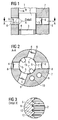
- FIGS. 1 to 3 an actuator 1 according to a first embodiment of the present invention described.
- the actuator 1 is arranged in a mounting hole 14 of an injector 7.
- the actuator 1 consists of a top plate 2, a piezo stack 3, which is arranged in a tube spring 4, and a bottom plate, not shown:
- About the bottom plate of the actuator 1 is connected in known manner with a translator for the translation of Aktorhubes to an injection needle of the To lift the injector from its seat and to perform an injection of fuel into a combustion chamber or end.
- each recess 8 have a supplementary material 6 is arranged, which is used for caulking the top plate 2 of the actuator with the injector 7. Thus arise between the top plate 2 and the injector 7 four caulked areas 5 (see. FIG. 2 ).
- FIG. 3 a caulked area 5 is shown enlarged.
- a plurality of grooves 12 are formed, which are arranged parallel to each other. In this case, the grooves 12 extend around the entire outer circumference of the cylindrical head plate 2. These grooves 12 provide a surface structuring of the top plate 2 ready to ensure a suitable tread depth for caulking.
- the additional material 6 is arranged in the grooves 12 after caulking, so that a secure attachment of the actuator 1 to the injector 7 can be ensured.
- FIG. 2 how out FIG. 2 it can be seen, two cable bushings 11 are further provided in the top plate 2, to provide an electrical connection for the piezo stack. Furthermore, a high-pressure bore 9 and a leakage bore 10 are provided in the injector housing 7.
- the actuator 1 is first arranged in the injector 7 in the mounting hole 14. In this case, the actuator 1 is positioned such that the bottom plate, not shown, is aligned in its predetermined position. Subsequently, the four additional materials 6 are arranged in the recesses 8 in the injector 7 and caulked by pressing a ram. This results in four caulked areas 5 between the additional material 6 and the top plate 2 and the additional material 6 and the injector 7.
- additional material for caulking a cold extrusion steel is preferably used, which has excellent Verstemmeigenticianen.
- the actuator 1 can be fixed in an optimal position in the injector without the need for expensive reworking.
- a disadvantageous addition of different tolerances of the individual components can be prevented by caulking.
- a compensation of manufacturing tolerances of the actuator 1, such. B. length tolerances of the piezo stack 3, the top plate 2 or the bottom plate carried out by an exact positioning of the preassembled actuator with respect to a arranged in the injector 7 reference surface.
- an electrical connector can be easily anchored in the recesses 8 after caulking, for example by means of plastic syringes.
- the illustrated actuator 1 is used in particular in an injector for a storage injection system, such as a common rail system. Due to the integral arrangement of the actuator 1 in the injector 7, the injector may have particularly small and compact dimensions. Furthermore, a tempering steel can be used by caulking, so that a simpler production of both the top plate 2 and the injector 7 result.
- FIGS. 4 and 5 an actuator 1 according to a second embodiment of the present invention described.
- the same reference numerals are used for similar parts.
- the actuator 1 of the second embodiment substantially corresponds to that of the first embodiment.
- no additional Verstemmaterialien are provided in the second embodiment, but as a material for caulking material 13 of the injector 7 is used.
- 7 blind holes 8 are provided in the injector, so that at the end of each blind hole each a material portion 13 stops, with which the caulking of the top plate 2 takes place.
- the actuator of the second embodiment corresponds to the first embodiment, so that reference may be made to the description given there.
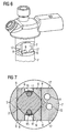
- the actuator of the third embodiment substantially corresponds to that of the first embodiment, wherein instead of radial bores tangential holes 8 are formed to the outer periphery of the top plate 2.
- the recesses 8 are formed on flattened areas 17 of the injector 7. In each case, two recesses 8 are arranged opposite one another, so that the four recesses 8 can be produced by means of only two holes, resulting in production-related cost advantages.
- the recesses 8 are formed tangentially to the bore for receiving the actuator.
- FIG. 7 the caulked state of the top plate 2 is shown. How out FIG. 7 can be seen, are used as Verstemmmaterial cylindrically caulking 6, preferably made of the well-formed material Cq 45. After caulking, the cylindrical caulking pins 6 are deformed such that they each form wedge-shaped caulked regions 5 between the top plate 2 and the injector housing 7. These wedge-shaped caulked areas 5 are based on the outside towards the injector housing 7 and inwards towards the top plate 2. The caulking thus takes place substantially tangentially to the outside of the top plate 2. It should be noted that, for an improved wedge effect, the outer periphery of the top plate 2 may be formed with flattened areas.
- a surface structuring for example in the form of a corrugation or the like, may be provided on the top plate 2.
- the flattened regions 17 on the injector housing 7 can also be used as anchoring, for example for an electrical plug-in connection or the like.
- FIG. 7 furthermore, the cables 15 and 16 arranged in the cable bushings 11 are shown for the electrical connection of the piezo stack.
- the present invention relates to an actuator 1 as a drive unit for an injector, in particular for a storage injection system, wherein the actuator comprises a arranged in a tube spring 4 piezo stack 3, a top plate 2 and a bottom plate.
- the actuator is attached to the top plate 2 by means of at least one caulked area 5 directly to an injector 7.
Abstract
Description
Die vorliegende Erfindung betrifft einen Aktor als Antriebseinheit eines Injektors insbesondere für ein Speichereinspritzsystem, wobei der Aktor einen in einer Rohrfeder angeordneten Piezostack, eine Kopfplatte und eine Bodenplatte umfasst. Weiterhin betrifft die vorliegende Erfindung ein Verfahren zur Herstellung des Injektors und insbesondere ein Montageverfahren zur Montage des Aktors in einem Injektor.The present invention relates to an actuator as a drive unit of an injector, in particular for a storage injection system, wherein the actuator comprises a arranged in a tube spring piezo stack, a top plate and a bottom plate. Furthermore, the present invention relates to a method for producing the injector, and more particularly to an assembly method for mounting the actuator in an injector.
Aktoren als Antriebseinheit für einen Injektor, welche einen Piezostack verwenden, sind in verschiedenen Ausführungsformen aus dem Stand der Technik bekannt. Dabei ist bei dem aus der
Zur Befestigung des Aktormoduls im Aktorgehäuse wird üblicherweise die Kopfplatte mit dem Aktorgehäuse verschweißt. Hierbei werden die vorhandenen Fertigungstoleranzen des Piezoaktors, wie z. B. die Länge des Piezostacks, durch ein positioniertes Verschweißen der Kopfplatte im Aktorgehäuse und durch anschließendes Planschleifen der Aktorbodenplatte gemeinsam mit dem Aktorgehäuse des darin eingeschweißten Piezoaktors, ausgeglichen. Bei den bekannten Aktoren ist einerseits nachteilig, dass dieses Planschleifen des montierten Aktors im Gehäuse einen zusätzlichen Arbeitsschritt erfordert sowie ungewünschte Belastungen des Aktors durch den zusätzlichen Fertigungsschritt hervorgerufen werden. Weiterhin muss auf Grund des Schweißens ein schweißbarer Stahl für die Kopfplatte sowie das Aktorgehäuse verwendet werden. Hierbei tritt weiter eine ungewünschte Wärmebelastung des Aktors auf und es können insbesondere Probleme an der Schweißnaht auftreten. Weiterhin benötigt die bekannte Anordnung des Aktors einen relativ großen Bauraum.For attachment of the actuator module in the actuator housing usually the top plate is welded to the actuator housing. Here, the existing manufacturing tolerances of the piezoelectric actuator, such. As the length of the piezo stack, by a positioned welding of the top plate in the actuator housing and by subsequent surface grinding of the Aktorbodenplatte together with the actuator housing of the piezoelectric actuator welded therein, balanced. In the known actuators on the one hand disadvantageous that this surface grinding of the assembled actuator in the housing requires an additional step and unwanted burdens of the actuator are caused by the additional manufacturing step. Furthermore, a weldable steel for the top plate and the actuator housing must be used due to the welding. This occurs Furthermore, an undesired heat load on the actuator and in particular problems can occur at the weld. Furthermore, the known arrangement of the actuator requires a relatively large amount of space.
Es ist daher Aufgabe der vorliegenden Erfindung, einen Aktor als Antriebseinheit für einen Injektor bereitzustellen, welcher einen einfacheren und kostengünstigen Aufbau aufweist. Weiterhin ist es Aufgabe der vorliegenden Erfindung, ein verbessertes Herstellverfahren für den Injektor bereitzustellen.It is therefore an object of the present invention to provide an actuator as a drive unit for an injector, which has a simpler and less expensive structure. It is another object of the present invention to provide an improved manufacturing method for the injector.
Diese Aufgabe wird durch einen Aktor mit den Merkmalen des Patentanspruchs 1 bzw. ein Verfahren mit den Merkmalen des Patentanspruchs 18 gelöst. Vorteilhafte Weiterbildungen sind Gegenstand der abhängigen Ansprüche.This object is achieved by an actuator having the features of
Der erfindungsgemäße Aktor als Antriebseinheit für einen Injektor mit den Merkmalen des Patentanspruchs 1 hat den Vorteil, dass er in das Injektorgehäuse integriert ist. Dadurch weist der erfindungsgemäße Aktor einen einfachen Aufbau und eine verringerte Teileanzahl auf. Insbesondere kann auf das im Stand der Technik verwendete Aktorgehäuse verzichtet werden. Weiterhin ist der erfindungsgemäße Aktor sehr einfach und kostengünstig herstellbar, da die Kopfplatte des Aktors mittels verstemmten Bereichen unmittelbar am Injektorgehäuse befestigt wird. Dadurch kann auf das im Stand der Technik verwendete, aufwändige Schweißen zur Befestigung des Aktors verzichtet werden. Weiterhin ist erfindungsgemäß eine lageoptimale Befestigung des Aktors im Injektorgehäuse möglich. Hierzu wird der Aktor vor dem Verstemmen im Injektorgehäuse an seiner vorbestimmten Position positioniert und anschließend mittels Verstemmen befestigt. Dadurch kann zum einen auf die aufwändige Nachbearbeitung der Bodenplatte des Aktors verzichtet werden und zum anderen ergibt sich durch die Positionierung und die anschließende Befestigung mittels der verstemmten Bereiche keine nachteilige Addition von herstellungsbedingten Toleranzen am Injektor. Hierzu wird der Aktor an seiner Kopfplatte mittels einem oder mehreren verstemmten Bereichen unmittelbar am Injektorgehäuse befestigt. Da weiter auf das im Stand der Technik verwendete Schweißen verzichtet werden kann, kann an Stelle eines Einsatzstahles für das Injektorgehäuse ein Vergütungsstahl verwendet werden, wodurch sich auf Grund des vereinfachten Fertigungsverfahrens für das Injektorgehäuse (keine mehrstufige Wärmebehandlung erforderlich) deutliche Kostenvorteile ergeben. Weiterhin kann durch Verzicht auf das Aktorgehäuse der Aktor einen verringerten maximalen Außendurchmesser aufweisen, so dass die Gesamtabmessungen des Injektors im Vergleich mit dem Stand der Technik verringert werden können und der Injektor kompakter aufgebaut sein kann.The actuator according to the invention as a drive unit for an injector with the features of
Vorzugsweise sind die verstemmten Bereiche seitlich an der Kopfplatte das Aktors angeordnet. Dadurch kann ein einfaches Verstemmen, beispielsweise mittels seitlich durch das Injektorgehäuse geführten Pressstempeln, ausgeführt werden.Preferably, the caulked areas are arranged on the side of the head plate, the actuator. As a result, a simple caulking, for example, by means of laterally guided through the injector housing dies are performed.
Gemäß einer anderen bevorzugten Ausgestaltung der vorliegenden Erfindung sind die verstemmten Bereiche am oberen, d. h. nach außen gerichteten, Bereich der Kopfplatte angeordnet. Es sei angemerkt, dass die verstemmten Bereiche sowohl am oberen Bereich der Kopfplatte als auch zusätzlich seitlich an der Kopfplatte angeordnet sein können.According to another preferred embodiment of the present invention, the caulked areas are at the top, d. H. outwardly directed, arranged area of the top plate. It should be noted that the caulked areas can be arranged both on the upper area of the top plate and additionally laterally on the top plate.
Besonders bevorzugt sind die verstemmten Bereiche radial oder im Wesentlichen tangential zum äußeren Umfang der Kopfplatte angeordnet. Insbesondere bei einer tangentialen Anordnung der verstemmten Bereiche zum äußeren Umfang der Kopfplatte kann nach dem Verstemmen eine besonders hohe Haltekraft für die Kopfplatte erreicht werden, da sich an den verstemmten Bereichen nach dem Verstemmen ein keilförmiger verstemmter Materialbereich ergibt. Dieser keilförmige Materialbereich stützt sich nach außen zum Injektorgehäuse und nach innen zur Kopfplatte ab. Dabei bleibt die vorteilhafte Wirkung der keilförmigen Verstemmung auch nach dem Verstemmvorgang erhalten.Particularly preferably, the caulked areas are arranged radially or substantially tangentially to the outer periphery of the top plate. Especially with a tangential arrangement of the caulked areas to the outer periphery of the top plate, a particularly high holding force for the top plate can be achieved after caulking, as results in a caulked caulked material area at the caulked areas after caulking. This wedge-shaped material area is supported outwards to the injector housing and inwards to the top plate. The advantageous effect of the wedge-shaped caulking is retained even after caulking.
Um eine möglichst geringe Teileanzahl aufzuweisen, sind die verstemmten Bereiche vorzugsweise aus Material des Injektorgehäuses gebildet. Hierzu können beispielsweise am Injektorgehäuse Sacklochbohrungen vorgesehen werden, wobei das Material am Ende der Sacklochbohrung zum Verstemmen mit der Kopfplatte des Aktors verwendet wird.In order to have the smallest possible number of parts, the caulked areas are preferably formed from the material of the injector housing. For this purpose, for example, blind holes can be provided on the injector housing, wherein the material is used at the end of the blind hole for caulking with the top plate of the actuator.
Gemäß einer anderen bevorzugten Ausgestaltung der vorliegenden Erfindung sind die verstemmten Bereiche aus einem Zusatzmaterial gebildet. Dadurch ist es möglich, das Zusatzmaterial derart auszuwählen, dass es die bestmöglichen Anforderungen hinsichtlich des Verstemmens erfüllen kann. Dadurch ergibt sich auch ein höherer Freiheitsgrad hinsichtlich der Auswahl des Materials für das Injektorgehäuse, da nicht mehr unmittelbar Material des Injektorgehäuses zum Verstemmen verwendet wird. Das Zusatzmaterial zum Verstemmen kann beispielsweise in Durchgangsbohrungen positioniert sein, welche im Injektorgehäuse ausgebildet sind und mittels Pressstempeln verstemmt werden.According to another preferred embodiment of the present invention, the caulked portions are formed of a filler material. This makes it possible to select the additional material so that it can meet the best possible requirements in terms of caulking. This also results in a higher degree of freedom with regard to the selection of the material for the injector, as no longer directly material of the injector is used for caulking. The additional material for caulking can be positioned for example in through holes which are formed in the injector and caulked by means of press dies.
Um eine besonders sichere und feste Verbindung an den verstemmten Bereichen zu ermöglichen, ist seitlich an der Kopfplatte des Aktors eine Oberflächenstrukturierung mit einer geeigneten Profiltiefe zum Verstemmen ausgebildet. Dadurch wird sichergestellt, dass Verstemmaterial beim Verstemmen in die Ausnehmungen der Oberflächenstrukturierung eingepresst wird und dadurch eine sichere Befestigung der Kopfplatte mittels Verstemmen gewährleistet ist.In order to enable a particularly secure and firm connection to the caulked areas, a surface structuring with a suitable tread depth for caulking is formed laterally on the head plate of the actuator. This ensures that Verstemmaterial is pressed during caulking in the recesses of the surface structuring and thereby secure attachment of the top plate is ensured by caulking.
Besonders bevorzugt ist die Oberflächenstrukturierung an der Kopfplatte als teilweise oder vollständig umlaufende Rillen ausgebildet. Dadurch kann die Oberflächenstrukturierung relativ kostengünstig hergestellt werden. Es sei angemerkt, dass die Oberflächenstrukturierung dabei über die gesamte Höhe der Kopfplatte oder auch nur im Bereich der verstemmten Bereiche gebildet sein kann. Gemäß einer besonders bevorzugten Ausgestaltung der vorliegenden Erfindung ist die Oberflächenstrukturierung an einer zylindrischen Kopfplatte als Gewinde ausgebildet. Dadurch kann die Oberflächenstrukturierung besonders kostengünstig hergestellt werden, indem an der zylindrischen Kopfplatte einfach ein Außengewinde vorgesehen ist.Particularly preferably, the surface structuring on the top plate is designed as partially or completely circumferential grooves. As a result, the surface structuring can be produced relatively inexpensively. It should be noted that the surface structuring can be formed over the entire height of the head plate or only in the region of the caulked areas. According to a particularly preferred embodiment According to the present invention, the surface structuring is formed on a cylindrical head plate as a thread. As a result, the surface structuring can be produced particularly inexpensively by simply providing an external thread on the cylindrical top plate.
Bevorzugt ist die Verbindung zwischen der Kopfplatte und dem Injektorgehäuse durch vier verstemmte Bereiche gebildet. Besonders bevorzugt sind die vier verstemmten Bereiche dabei derart angeordnet, dass sich jeweils zwei verstemmte Bereiche gegenüberliegen. Dadurch ergibt sich eine besonders günstige Krafteinleitung und Kraftverteilung auf die Kopfplatte. Weiterhin kann dadurch eine ungewünschten Verformung der Kopfplatte beim Durchführen des Verstemmens verhindert werden.Preferably, the connection between the top plate and the injector is formed by four caulked areas. Particularly preferably, the four caulked areas are arranged such that in each case two caulked areas opposite each other. This results in a particularly favorable introduction of force and force distribution on the top plate. Furthermore, it can prevent undesired deformation of the head plate in performing the caulking.
Um möglichst kostengünstig herstellbar zu sein, sind die Kopfplatte und/oder das Injektorgehäuse vorzugsweise aus einem Vergütungsstahl hergestellt. Besonders bevorzugt wird dabei als Vergütungsstahl 42CrMo4 verwendet. Als Zusatzmaterial für das Verstemmen wird vorzugsweise ein Kaltfließpressstahl, wie z.B. Cq45 verwendet.In order to be as inexpensive to produce, the top plate and / or the Injektorgehäuse are preferably made of a tempered steel. It is particularly preferred to use 42CrMo4 as the tempering steel. As a caulking additive, it is preferable to use a cold extrusion press steel, e.g. Cq45 used.
Vorteilhaft sind im Injektorgehäuse Aussparungen vorgesehen, an welchen die verstemmten Bereiche angeordnet sind. Die Aussparungen können dabei als Durchgangsbohrung oder als Sacklochbohrungen ausgebildet sein. Besonders bevorzugt dienen die Aussparungen nach dem Verstemmen zusätzlich noch als Verankerung für einen elektrischen Steckanschluss des Aktors. Der Steckanschluss wird dabei nach dem Verstemmen der Kopfplatte des Aktors mit dem Injektorgehäuse an den Aussparungen befestigt. Besonders bevorzugt ist der elektrische Steckanschluss dabei durch eine Kunststoffumspritzung gebildet, wobei der in die Aussparungen eingeführte Kunststoff die Verankerung bildet. Weiterhin werden dadurch die verstemmten Bereiche gut durch den Kunststoff eingekapselt, so dass an diesen Stellen keine Korrosion auftreten kann.Advantageously recesses are provided in the injector, to which the caulked areas are arranged. The recesses may be formed as a through hole or as blind holes. Particularly preferably, the recesses after caulking additionally serve as anchoring for an electrical plug connection of the actuator. The plug-in connection is attached to the recesses after caulking the head plate of the actuator with the injector. Particularly preferably, the electrical plug connection is formed by a plastic extrusion, wherein the introduced into the recesses plastic forms the anchorage. Furthermore, the caulked areas are well encapsulated by the plastic, so that no corrosion can occur at these locations.
Beim erfindungsgemäßen Verfahren zur Herstellung eines Injektors mit einem Aktor umfasst die Montage des Aktors in einem Injektorgehäuse die folgenden Schritte. Zuerst wird der aus einem in einer Rohrfeder angeordneten Piezostack, einer Kopfplatte und einer Bodenplatte bestehende Aktor vormontiert. Anschließend wird der vormontierte Aktor in einem Injektorgehäuse positioniert, indem die Bodenplatte an ihrer vorbestimmten Position im Injektorgehäuse ausgerichtet wird. Danach wird der Aktor am Injektorgehäuse mittels Verstemmen zwischen der Kopfplatte und dem Injektorgehäuse befestigt. Zum Verstemmen kann dabei Material des Injektorgehäuses und/oder der Kopfplatte und/oder ein zusätzliches Verstemmaterial verwendet werden.In the method according to the invention for producing an injector with an actuator, the assembly of the actuator in an injector housing comprises the following steps. First, the actuator consisting of a piezostack arranged in a tube spring, a top plate and a bottom plate is preassembled. Subsequently, the preassembled actuator is positioned in an injector housing by aligning the bottom plate at its predetermined position in the injector housing. Thereafter, the actuator is attached to the injector housing by caulking between the top plate and the injector housing. For caulking while the material of the injector and / or the top plate and / or an additional Verstemmaterial be used.
Vorzugsweise umfasst das Verfahren zur Herstellung eines Injektors weiterhin den Schritt des Kunststoffspritzens einer elektrischen Steckverbindung an das Injektorgehäuse, wobei die elektrische Steckverbindung in Aussparungen im Injektorgehäuse verankert ist, welche zum Durchführen des Verstemmens verwendet werden.Preferably, the method for manufacturing an injector further comprises the step of plastic injection of an electrical connector to the injector housing, wherein the electrical connector is anchored in recesses in the injector housing, which are used for performing the caulking.
Nachfolgend wird die Erfindung anhand von bevorzugten Ausführungsbeispielen in Verbindung mit der Zeichnung beschrieben. In der Zeichnung ist:
-
Figur 1 -
Figur 2A-A von Figur 1 ; -
Figur 3X von Figur 1; -
Figur 4Figur 5B-B von Figur 4 ; -
Figur 6 -
Figur 7Figur 6
-
FIG. 1 a schematic sectional view of an actuator according to a first embodiment of the present invention; -
FIG. 2 a schematic sectional view taken along the line AA ofFIG. 1 ; -
FIG. 3 an enlarged detail view of the detail X of Figure 1; -
FIG. 4 a schematic sectional view of an actuator according to a second embodiment of the present invention;FIG. 5 a schematic sectional view taken along the line BB ofFIG. 4 ; -
FIG. 6 a schematic perspective, partially sectioned view of an injector with an actuator according to a third embodiment of the present invention; and -
FIG. 7 a schematic sectional view of the inFIG. 6 shown actuator.
Nachfolgend wird unter Bezugnahme auf die
Wie in
Wie insbesondere aus den
Wie insbesondere in
Wie aus
Um den als vormontierte Baugruppe vorbereiteten Aktor 1 im Injektorgehäuse 7 zu befestigen, wird zuerst der Aktor 1 im Injektorgehäuse 7 in der Montagebohrung 14 angeordnet. Dabei wird der Aktor 1 derart positioniert, dass die nicht dargestellte Bodenplatte in ihrer vorbestimmten Position ausgerichtet wird. Anschließend werden die vier Zusatzmaterialien 6 in die Aussparungen 8 im Injektorgehäuse 7 angeordnet und mittels Eindrücken eines Pressstempels verstemmt. Dadurch entstehen vier verstemmte Bereiche 5 zwischen dem Zusatzmaterial 6 und der Kopfplatte 2 bzw. dem Zusatzmaterial 6 und dem Injektorgehäuse 7. Als Zusatzmaterial für das Verstemmen wird vorzugsweise ein Kaltfließpressstahl verwendet, welcher hervorragende Verstemmeigenschaften aufweist.In order to fix the prepared as a
Dadurch kann erfindungsgemäß der Aktor 1 lageoptimal im Injektor befestigt werden, ohne dass aufwändige Nachbearbeitungen notwendig sind. Insbesondere kann erfindungsgemäß eine nachteilige Addition unterschiedlicher Toleranzen der einzelnen Bauteile durch das Verstemmen verhindert werden. Genauer kann erfindungsgemäß ein Ausgleich von Fertigungstoleranzen des Aktors 1, wie z. B. Längentoleranzen des Piezostacks 3, der Kopfplatte 2 oder der Bodenplatte, durch ein exaktes Positionieren des vormontierten Aktors in Bezug auf eine im Injektorgehäuse 7 angeordnete Referenzfläche erfolgen. Weiterhin kann in den Aussparungen 8 nach dem Verstemmen ein elektrischer Steckeranschluss beispielsweise mittels Kunststoffspritzen einfach verankert werden.As a result, according to the invention, the
Der dargestellte Aktor 1 wird insbesondere in einem Injektor für ein Speichereinspritzsystem, wie beispielsweise einem Common-Rail-System, verwendet. Durch die integrale Anordnung des Aktors 1 im Injektorgehäuse 7 kann der Injektor besonders kleine und kompakte Abmessungen aufweisen. Weiterhin kann durch das Verstemmen ein Vergütungsstahl verwendet werden, so dass sich eine einfachere Herstellung sowohl der Kopfplatte 2 als auch des Injektorgehäuses 7 ergeben.The illustrated
Nachfolgend wird unter Bezugnahme auf die
Der Aktor 1 des zweiten Ausführungsbeispiels entspricht im Wesentlichen dem des ersten Ausführungsbeispiels. Im Unterschied zum ersten Ausführungsbeispiel sind im zweiten Ausführungsbeispiel jedoch keine zusätzlichen Verstemmaterialien vorgesehen, sondern als Material für das Verstemmen wird Material 13 des Injektorgehäuses 7 verwendet. Hierzu sind im Injektorgehäuse 7 Sackbohrungen 8 vorgesehen, so dass am Ende jeder Sacklochbohrung jeweils ein Materialanteil 13 stehen bleibt, mit welchem das Verstemmen der Kopfplatte 2 erfolgt. Ansonsten entspricht der Aktor des zweiten Ausführungsbeispiels dem ersten Ausführungsbeispiel, so dass auf die dort gegebene Beschreibung verwiesen werden kann.The
Nachfolgend wird unter Bezugnahme auf die
Der Aktor des dritten Ausführungsbeispiels entspricht im Wesentlichen dem des ersten Ausführungsbeispiels, wobei anstelle von radialen Bohrungen tangentiale Bohrungen 8 zum äußeren Umfang der Kopfplatte 2 gebildet sind. Wie aus den
In
In
Somit betrifft die vorliegende Erfindung einen Aktor 1 als Antriebseinheit für einen Injektor, insbesondere für ein Speichereinspritzsystem, wobei der Aktor einen in einer Rohrfeder 4 angeordneten Piezostack 3, eine Kopfplatte 2 und eine Bodenplatte umfasst. Der Aktor ist an der Kopfplatte 2 mittels wenigstens einem verstemmtem Bereich 5 unmittelbar an einem Injektorgehäuse 7 befestigt. Durch das Verstemmen ergibt sich dabei eine einfache und kostengünstige Herstellbarkeit des Injektors.Thus, the present invention relates to an
Die vorliegenden Erfindung ist nicht auf die dargestellten Ausführungsbeispiele beschränkt. Es können verschiedene Abweichungen und Änderungen ausgeführt werden, die in den Schutzbereich der beigefügten Ansprüche fallen, ohne den Erfindungsumfang zu verlassen.The present invention is not limited to the illustrated embodiments. Various modifications and changes may be made which fall within the scope of the appended claims without departing from the scope of the invention.
Claims (20)
- Actuator acting as a drive unit of an injector, especially for an accumulator injection system, whereby the actuator (1) comprises a piezostack (3) disposed in a tube spring (4), a top plate (2) and a bottom plate, with the top plate (2) of the actuator (1) being fastened on an injector housing, characterised in that the top plate (2) of the actuator (1) is fixed on the injector housing (7) by means of caulked areas (5).
- Actuator according to claim 1, characterised in that the caulked areas (5) are disposed on the sides of the top plate (2).
- Actuator according to claim 1 or 2, characterised in that the caulked areas (5) are disposed on the upper area of the top plate (2).
- Actuator according to one of claims 1 to 3, characterised in that the caulked areas (5) are disposed radially in respect of the outer periphery of the top plate (2).
- Actuator according to one of claims 1 to 3, characterised in that the caulked areas (5) are disposed essentially tangentially in respect of the outer periphery of the top plate (2).
- Actuator according to one of claims 1 to 5, characterised in that the caulked areas (5) are formed from the material of the injector housing (7).
- Actuator according to one of claims 1 to 5, characterised in that the caulked areas (5) are formed from a filler material (6).
- Actuator according to one of claims 1 to 7, characterised in that a surface structure is configured on the top plate (2) with a suitable profile depth for caulking.
- Actuator according to claim 8, characterised in that the surface structure on the top plate (2) is configured as partially or wholly circumferential grooves (12).
- Actuator according to claim 8, characterised in that the top plate (2) is configured as a cylinder and the surface structure on the top plate (2) is configured as an external thread.
- Actuator according to one of claims 1 to 10, characterised in that the connection between the top plate (2) and the injector housing (7) is formed by four caulked areas (5).
- Actuator according to claim 11, characterised in that the four caulked areas (5) are disposed in such a way that two caulked areas (5) lie opposite each other on the top plate (2) in each instance.
- Actuator according to one of claims 1 to 12, characterised in that the top plate (2) and/or the injector housing (7) are made of a tempering steel.
- Actuator according to claim 13, characterised in that 42CrMo4 is used as the tempering steel.
- Actuator according to one of claims 1 to 14, characterised in that cutouts (8) are provided in the injector housing (7), at which the caulked areas (5) are disposed.
- Actuator according to claim 15, characterised in that the cutouts (8) serve as anchorage points for an electric plug-type connection of the actuator.
- Actuator according to claim 16, characterised in that the electrical plug-type connection is configured as a plastic extrusion coating.
- Method for producing an injector with an actuator (1), whereby the assembly of the actuator (1) to activate the injector in an injector housing (7) comprises the following stages:- Pre-assembly of the actuator (1) comprising a piezostack (3) disposed in a tube spring (4), a top plate (2) and a bottom plate,- Positioning of the pre-assembled actuator (1) in the injector housing (7) by lining up the actuator, especially by lining up the bottom plate with its predefined position and- Fixing the actuator (1) on the injector housing (7), characterised in that the actuator (1) is fixed on the injector housing (7) by means of caulking between the top plate (2) and the injector housing (7).
- Method according to claim 18, characterised in that the material of the top plate (2) and/or the material (13) of the injector housing and/or a filler material (6) is used for caulking.
- Method according to claim 18 or 19, characterised in that cutouts (8) are formed in the injector housing (7) for caulking and these are used after caulking to anchor a plastic injected electrical plug-type connection.
Applications Claiming Priority (3)
| Application Number | Priority Date | Filing Date | Title |
|---|---|---|---|
| DE10140530 | 2001-08-17 | ||
| DE10140530 | 2001-08-17 | ||
| PCT/EP2002/009178 WO2003016702A2 (en) | 2001-08-17 | 2002-08-16 | Actuator acting as a drive unit for an injector and method for the production of said injector |
Publications (2)
| Publication Number | Publication Date |
|---|---|
| EP1417406A2 EP1417406A2 (en) | 2004-05-12 |
| EP1417406B1 true EP1417406B1 (en) | 2008-10-15 |
Family
ID=7695852
Family Applications (1)
| Application Number | Title | Priority Date | Filing Date |
|---|---|---|---|
| EP02774517A Expired - Fee Related EP1417406B1 (en) | 2001-08-17 | 2002-08-16 | Actuator acting as a drive unit for an injector and method for the production of said injector |
Country Status (5)
| Country | Link |
|---|---|
| US (1) | US7030541B2 (en) |
| EP (1) | EP1417406B1 (en) |
| JP (1) | JP4331594B2 (en) |
| DE (1) | DE50212908D1 (en) |
| WO (1) | WO2003016702A2 (en) |
Family Cites Families (18)
| Publication number | Priority date | Publication date | Assignee | Title |
|---|---|---|---|---|
| US3733661A (en) * | 1971-01-25 | 1973-05-22 | List H | Method for the manufacture of a piezoelectric transducer and transducer manufactured by this method |
| DE3540660A1 (en) | 1985-11-16 | 1987-05-21 | Bosch Gmbh Robert | Solenoid-operatable fuel injection valve |
| DE3629646A1 (en) | 1986-08-30 | 1988-03-03 | Bosch Gmbh Robert | ELECTROMAGNETICALLY ACTUABLE FUEL INJECTION VALVE |
| DE3878599T2 (en) * | 1987-06-26 | 1993-09-23 | Hitachi Ltd | ELECTROMAGNETIC FUEL INJECTION VALVE. |
| DE3864772D1 (en) * | 1987-07-21 | 1991-10-17 | Nippon Denso Co | METHOD FOR ADJUSTING THE FUEL INJECTION AMOUNT OF AN ELECTROMAGNETIC FUEL INJECTION VALVE. |
| DE3817947A1 (en) | 1988-05-27 | 1989-11-30 | Bayerische Motoren Werke Ag | Vehicle wheel with a signal transmitter |
| US4974780A (en) * | 1988-06-22 | 1990-12-04 | Toa Nenryo Kogyo K.K. | Ultrasonic fuel injection nozzle |
| JPH05315666A (en) * | 1992-05-08 | 1993-11-26 | Nec Corp | Electrostriction effect element |
| DE4428309A1 (en) | 1993-08-24 | 1995-03-02 | Schaeffler Waelzlager Kg | Valve bucket tappet |
| DE19744762A1 (en) | 1997-03-18 | 1998-10-01 | Poppe & Potthoff Gmbh & Co | Injection device for a diesel engine |
| DE19826341A1 (en) | 1998-06-12 | 1999-12-16 | Bosch Gmbh Robert | Valve for controlling liquids |
| DE19832826C2 (en) | 1998-07-21 | 2000-08-17 | Bosch Gmbh Robert | Assembly procedure for fuel injector and pilot valve and fuel injector |
| DE19858085C1 (en) * | 1998-12-16 | 2000-03-30 | Siemens Ag | Control drive for fuel injector for internal combustion engine |
| EP1046809B1 (en) * | 1999-04-20 | 2005-08-10 | Siemens Aktiengesellschaft | Fluid metering device |
| DE19958705C2 (en) * | 1999-12-06 | 2003-03-13 | Siemens Ag | Valve with improved stop geometry |
| DE19958704C2 (en) | 1999-12-06 | 2002-10-02 | Siemens Ag | Device for transmitting an actuator movement and fluid metering device with such a device |
| DE19962177A1 (en) * | 1999-12-22 | 2001-07-12 | Siemens Ag | Hydraulic device for transmitting an actuator movement |
| US6279842B1 (en) * | 2000-02-29 | 2001-08-28 | Rodi Power Systems, Inc. | Magnetostrictively actuated fuel injector |
-
2002
- 2002-08-16 EP EP02774517A patent/EP1417406B1/en not_active Expired - Fee Related
- 2002-08-16 JP JP2003520971A patent/JP4331594B2/en not_active Expired - Fee Related
- 2002-08-16 WO PCT/EP2002/009178 patent/WO2003016702A2/en active Application Filing
- 2002-08-16 DE DE50212908T patent/DE50212908D1/en not_active Expired - Lifetime
-
2004
- 2004-02-17 US US10/780,016 patent/US7030541B2/en not_active Expired - Lifetime
Also Published As
| Publication number | Publication date |
|---|---|
| WO2003016702A2 (en) | 2003-02-27 |
| DE50212908D1 (en) | 2008-11-27 |
| JP2004538420A (en) | 2004-12-24 |
| US7030541B2 (en) | 2006-04-18 |
| EP1417406A2 (en) | 2004-05-12 |
| US20040169443A1 (en) | 2004-09-02 |
| JP4331594B2 (en) | 2009-09-16 |
| WO2003016702A3 (en) | 2003-10-23 |
Similar Documents
| Publication | Publication Date | Title |
|---|---|---|
| EP1906464B1 (en) | Piezo actuator with a jacket for placing in a piezo injector | |
| DE102007000128B4 (en) | Injector | |
| EP2409014B1 (en) | High pressure pump and tappet assembly | |
| DE69735451T2 (en) | A threaded cylinder fuel injector for mounting a fuel injector on an internal combustion engine | |
| WO2001006167A1 (en) | Connection and housing, especially a high-pressure fuel accumulator, with a connection that is welded on in a prestressed manner, for a fuel injection system for internal combustion engines | |
| DE3915440A1 (en) | METHOD FOR PRODUCING A FUEL DISTRIBUTOR FOR THE FUEL SUPPLY SYSTEM OF AN ENGINE WITH INTERNAL COMBUSTION | |
| DE19913679B4 (en) | Pinned injector assembly | |
| EP1775460B1 (en) | Fuel injection valve | |
| EP2529103B1 (en) | Method for the high-pressure-tight connection of at least one plate-shaped body to a further body of a fuel injector and fuel injector | |
| EP1417406B1 (en) | Actuator acting as a drive unit for an injector and method for the production of said injector | |
| EP3049666B1 (en) | Piezo injector for direct injection of fuel | |
| EP1630408B1 (en) | Fuel injector for an internal combustion engine and method for mounting such an injector | |
| DE10322595B4 (en) | Piston pump, and process for its preparation | |
| EP2592260B1 (en) | Fuel injector, method for the assembly of a fuel injector and tensioning device for mounting of a fuel injector | |
| EP3109911B1 (en) | Piezo actuator module, method for producing a piezo actuator module and piezo injector | |
| DE19848845A1 (en) | Ram device for a fuel injector | |
| WO2004047191A2 (en) | Piezo actuator contact mechanism for an injection valve and method for producing said actuator | |
| DE102004008450B4 (en) | Method and device for producing a composite component | |
| DE102004040072B4 (en) | Sealing arrangement of a piezoelectric actuator and method for sealing a piezoelectric actuator | |
| WO2000031410A1 (en) | Device for disassembling a fuel injection valve | |
| DE19843915A1 (en) | Component connection for high pressure conduction | |
| EP2596231B1 (en) | Fuel injector having a hydraulic coupler unit | |
| EP2539575A1 (en) | Fuel injector and method for the manufacture and/or assembly of a nozzle needle assembly | |
| DE102005024196A1 (en) | Fuel injector with a piezo actuator for the injection valve, for an internal combustion motor, has a connecting component group with connection sections for the actuator electrical contact | |
| DE102015211780A1 (en) | Fuel injector and method for assembling a fuel injector |
Legal Events
| Date | Code | Title | Description |
|---|---|---|---|
| PUAI | Public reference made under article 153(3) epc to a published international application that has entered the european phase |
Free format text: ORIGINAL CODE: 0009012 |
|
| 17P | Request for examination filed |
Effective date: 20040202 |
|
| AK | Designated contracting states |
Kind code of ref document: A2 Designated state(s): AT BE BG CH CY CZ DE DK EE ES FI FR GB GR IE IT LI LU MC NL PT SE SK TR |
|
| RIN1 | Information on inventor provided before grant (corrected) |
Inventor name: BLOCHING, WOLFGANG Inventor name: SCHUERZ, WILLIBALD Inventor name: SIMMET, MARTIN Inventor name: DICK, JUERGEN |
|
| GRAP | Despatch of communication of intention to grant a patent |
Free format text: ORIGINAL CODE: EPIDOSNIGR1 |
|
| RAP1 | Party data changed (applicant data changed or rights of an application transferred) |
Owner name: CONTINENTAL AUTOMOTIVE GMBH |
|
| GRAS | Grant fee paid |
Free format text: ORIGINAL CODE: EPIDOSNIGR3 |
|
| GRAA | (expected) grant |
Free format text: ORIGINAL CODE: 0009210 |
|
| AK | Designated contracting states |
Kind code of ref document: B1 Designated state(s): DE FR GB IT |
|
| REG | Reference to a national code |
Ref country code: GB Ref legal event code: FG4D Free format text: NOT ENGLISH |
|
| REF | Corresponds to: |
Ref document number: 50212908 Country of ref document: DE Date of ref document: 20081127 Kind code of ref document: P |
|
| PLBE | No opposition filed within time limit |
Free format text: ORIGINAL CODE: 0009261 |
|
| STAA | Information on the status of an ep patent application or granted ep patent |
Free format text: STATUS: NO OPPOSITION FILED WITHIN TIME LIMIT |
|
| PG25 | Lapsed in a contracting state [announced via postgrant information from national office to epo] |
Ref country code: IT Free format text: LAPSE BECAUSE OF FAILURE TO SUBMIT A TRANSLATION OF THE DESCRIPTION OR TO PAY THE FEE WITHIN THE PRESCRIBED TIME-LIMIT Effective date: 20081015 |
|
| 26N | No opposition filed |
Effective date: 20090716 |
|
| GBPC | Gb: european patent ceased through non-payment of renewal fee |
Effective date: 20090816 |
|
| PG25 | Lapsed in a contracting state [announced via postgrant information from national office to epo] |
Ref country code: GB Free format text: LAPSE BECAUSE OF NON-PAYMENT OF DUE FEES Effective date: 20090816 |
|
| REG | Reference to a national code |
Ref country code: FR Ref legal event code: PLFP Year of fee payment: 15 |
|
| REG | Reference to a national code |
Ref country code: FR Ref legal event code: PLFP Year of fee payment: 16 |
|
| REG | Reference to a national code |
Ref country code: FR Ref legal event code: PLFP Year of fee payment: 17 |
|
| PGFP | Annual fee paid to national office [announced via postgrant information from national office to epo] |
Ref country code: DE Payment date: 20180831 Year of fee payment: 17 Ref country code: FR Payment date: 20180827 Year of fee payment: 17 |
|
| REG | Reference to a national code |
Ref country code: DE Ref legal event code: R119 Ref document number: 50212908 Country of ref document: DE |
|
| PG25 | Lapsed in a contracting state [announced via postgrant information from national office to epo] |
Ref country code: DE Free format text: LAPSE BECAUSE OF NON-PAYMENT OF DUE FEES Effective date: 20200303 Ref country code: FR Free format text: LAPSE BECAUSE OF NON-PAYMENT OF DUE FEES Effective date: 20190831 |