EP2409014B1 - High pressure pump and tappet assembly - Google Patents
High pressure pump and tappet assembly Download PDFInfo
- Publication number
- EP2409014B1 EP2409014B1 EP10700440.0A EP10700440A EP2409014B1 EP 2409014 B1 EP2409014 B1 EP 2409014B1 EP 10700440 A EP10700440 A EP 10700440A EP 2409014 B1 EP2409014 B1 EP 2409014B1
- Authority
- EP
- European Patent Office
- Prior art keywords
- pressure pump
- pump
- receptacle
- roller shoe
- centering guide
- Prior art date
- Legal status (The legal status is an assumption and is not a legal conclusion. Google has not performed a legal analysis and makes no representation as to the accuracy of the status listed.)
- Active
Links
- 239000000446 fuel Substances 0.000 claims description 13
- 238000002485 combustion reaction Methods 0.000 claims description 9
- 238000002347 injection Methods 0.000 claims description 5
- 239000007924 injection Substances 0.000 claims description 5
- 238000000034 method Methods 0.000 description 6
- 238000009434 installation Methods 0.000 description 5
- 238000003825 pressing Methods 0.000 description 5
- 230000002411 adverse Effects 0.000 description 2
- 230000003313 weakening effect Effects 0.000 description 2
- 206010067482 No adverse event Diseases 0.000 description 1
- 230000006835 compression Effects 0.000 description 1
- 238000007906 compression Methods 0.000 description 1
- 230000002349 favourable effect Effects 0.000 description 1
- 238000003780 insertion Methods 0.000 description 1
- 230000037431 insertion Effects 0.000 description 1
- 238000004519 manufacturing process Methods 0.000 description 1
Images

Classifications
-
- F—MECHANICAL ENGINEERING; LIGHTING; HEATING; WEAPONS; BLASTING
- F02—COMBUSTION ENGINES; HOT-GAS OR COMBUSTION-PRODUCT ENGINE PLANTS
- F02M—SUPPLYING COMBUSTION ENGINES IN GENERAL WITH COMBUSTIBLE MIXTURES OR CONSTITUENTS THEREOF
- F02M59/00—Pumps specially adapted for fuel-injection and not provided for in groups F02M39/00 -F02M57/00, e.g. rotary cylinder-block type of pumps
- F02M59/02—Pumps specially adapted for fuel-injection and not provided for in groups F02M39/00 -F02M57/00, e.g. rotary cylinder-block type of pumps of reciprocating-piston or reciprocating-cylinder type
- F02M59/04—Pumps specially adapted for fuel-injection and not provided for in groups F02M39/00 -F02M57/00, e.g. rotary cylinder-block type of pumps of reciprocating-piston or reciprocating-cylinder type characterised by special arrangement of cylinders with respect to piston-driving shaft, e.g. arranged parallel to that shaft or swash-plate type pumps
- F02M59/06—Pumps specially adapted for fuel-injection and not provided for in groups F02M39/00 -F02M57/00, e.g. rotary cylinder-block type of pumps of reciprocating-piston or reciprocating-cylinder type characterised by special arrangement of cylinders with respect to piston-driving shaft, e.g. arranged parallel to that shaft or swash-plate type pumps with cylinders arranged radially to driving shaft, e.g. in V or star arrangement
-
- F—MECHANICAL ENGINEERING; LIGHTING; HEATING; WEAPONS; BLASTING
- F02—COMBUSTION ENGINES; HOT-GAS OR COMBUSTION-PRODUCT ENGINE PLANTS
- F02M—SUPPLYING COMBUSTION ENGINES IN GENERAL WITH COMBUSTIBLE MIXTURES OR CONSTITUENTS THEREOF
- F02M59/00—Pumps specially adapted for fuel-injection and not provided for in groups F02M39/00 -F02M57/00, e.g. rotary cylinder-block type of pumps
- F02M59/02—Pumps specially adapted for fuel-injection and not provided for in groups F02M39/00 -F02M57/00, e.g. rotary cylinder-block type of pumps of reciprocating-piston or reciprocating-cylinder type
- F02M59/10—Pumps specially adapted for fuel-injection and not provided for in groups F02M39/00 -F02M57/00, e.g. rotary cylinder-block type of pumps of reciprocating-piston or reciprocating-cylinder type characterised by the piston-drive
- F02M59/102—Mechanical drive, e.g. tappets or cams
-
- F—MECHANICAL ENGINEERING; LIGHTING; HEATING; WEAPONS; BLASTING
- F04—POSITIVE - DISPLACEMENT MACHINES FOR LIQUIDS; PUMPS FOR LIQUIDS OR ELASTIC FLUIDS
- F04B—POSITIVE-DISPLACEMENT MACHINES FOR LIQUIDS; PUMPS
- F04B1/00—Multi-cylinder machines or pumps characterised by number or arrangement of cylinders
- F04B1/04—Multi-cylinder machines or pumps characterised by number or arrangement of cylinders having cylinders in star- or fan-arrangement
- F04B1/0404—Details or component parts
- F04B1/0408—Pistons
-
- F—MECHANICAL ENGINEERING; LIGHTING; HEATING; WEAPONS; BLASTING
- F04—POSITIVE - DISPLACEMENT MACHINES FOR LIQUIDS; PUMPS FOR LIQUIDS OR ELASTIC FLUIDS
- F04B—POSITIVE-DISPLACEMENT MACHINES FOR LIQUIDS; PUMPS
- F04B1/00—Multi-cylinder machines or pumps characterised by number or arrangement of cylinders
- F04B1/04—Multi-cylinder machines or pumps characterised by number or arrangement of cylinders having cylinders in star- or fan-arrangement
- F04B1/0404—Details or component parts
- F04B1/0413—Cams
- F04B1/0417—Cams consisting of two or more cylindrical elements, e.g. rollers
-
- F—MECHANICAL ENGINEERING; LIGHTING; HEATING; WEAPONS; BLASTING
- F04—POSITIVE - DISPLACEMENT MACHINES FOR LIQUIDS; PUMPS FOR LIQUIDS OR ELASTIC FLUIDS
- F04B—POSITIVE-DISPLACEMENT MACHINES FOR LIQUIDS; PUMPS
- F04B1/00—Multi-cylinder machines or pumps characterised by number or arrangement of cylinders
- F04B1/04—Multi-cylinder machines or pumps characterised by number or arrangement of cylinders having cylinders in star- or fan-arrangement
- F04B1/0404—Details or component parts
- F04B1/0426—Arrangements for pressing the pistons against the actuated cam; Arrangements for connecting the pistons to the actuated cam
-
- Y—GENERAL TAGGING OF NEW TECHNOLOGICAL DEVELOPMENTS; GENERAL TAGGING OF CROSS-SECTIONAL TECHNOLOGIES SPANNING OVER SEVERAL SECTIONS OF THE IPC; TECHNICAL SUBJECTS COVERED BY FORMER USPC CROSS-REFERENCE ART COLLECTIONS [XRACs] AND DIGESTS
- Y10—TECHNICAL SUBJECTS COVERED BY FORMER USPC
- Y10T—TECHNICAL SUBJECTS COVERED BY FORMER US CLASSIFICATION
- Y10T74/00—Machine element or mechanism
- Y10T74/21—Elements
- Y10T74/2101—Cams
- Y10T74/2107—Follower
Definitions
- the present invention relates to a high pressure pump for a fuel injection device of an internal combustion engine according to the preamble of claim 1 and a plunger assembly for a high pressure pump according to the preamble of claim 10.
- High-pressure pumps for fuel injectors of internal combustion engines are known in the prior art, which have a plunger assembly with pressed into a plunger body roller shoe.
- the plunger assembly is driven by a rotationally driven drive shaft of the high pressure pump, for example, against the force of a return spring in a lifting movement.
- a high-pressure pump is described with at least one plunger assembly, which in turn has a hollow cylindrical plunger body and a roller shoe inserted therein in the direction of the longitudinal axis of the plunger body, in which a roller is rotatably mounted.
- the high-pressure pump has at least one pump element, which in turn has a pump piston, by which a pump working space is limited.
- the plunger assembly is disposed between the pump piston and a rotationally driven drive shaft of the high pressure pump, wherein the drive shaft has at least one cam or eccentric on which the roller runs.
- the plunger body is guided displaceably in a bore of a housing part of the high-pressure pump.
- the ram assembly serves to the rotational movement of the drive shaft in a To convert stroke movement of the pump piston.
- the roller shoe is press-fitted into the ram body.
- a high-pressure pump for a fuel injection device of an internal combustion engine, which has at least one pump element with a pump piston defining a pump chamber, wherein between the pump piston and a drive shaft of the high-pressure pump driven in rotation, a plunger assembly is provided with a plunger body and a pressed into a receptacle of the plunger body roller shoe wherein the plunger body has a centering guide for pressing the roller shoe.
- the provision according to the invention of the centering guide enables an improved press-fitting of the roller shoe into the tappet body. A Schräginpressung is avoided, the centering an automatic centering is achieved, and thereby a robust ram assembly interference fit is created.
- the centering guide is provided in the region of the receptacle.
- the receptacle is cylindrical section-shaped, wherein the receptacle has an inner circumference, on which the centering guide is provided.
- the centering guide on a chamfer is a chamfer.
- the receptacle has a first end portion and a second end portion, wherein at the second end portion a radially projecting from the inner periphery inwardly abragender stop or projection is provided, and wherein the first end portion of an element of the drive shaft, in particular a cam or an eccentric , is opposite.
- the centering guide is provided at the first end portion.
- the centering guide is provided over a height of the first end portion in a range of 2 to 10 mm, in particular 4 mm.
- the chamfer has a depth a in the range of 0.1 to 0.01 mm, in particular of 0.05 mm, and in an angle range of 30 to 60 °, in particular with an angle of 45 ° is trained.
- a weakening of the plunger body by a centering guide with the above dimensions or in the above dimensional ranges has no adverse effects on the ram assembly interference fit. Neither the axial distance between the plunger body and the roller shoe is negatively affected in the plunger assembly during insertion or a pressure relief after pressing compared to a plunger assembly without centering, still affects a centering with the dimensions given above on the radial deformation of the plunger body during the pressing in and subsequent pressure relief negative. Rather, arises in terms of Plunger body with centering a more favorable deformation of the plunger body.
- the roller shoe is formed with a cylindrical excess pressure, which in particular has a value P ü, nenn of 9 microns.
- a plunger assembly for a high-pressure pump for a fuel injector of an internal combustion engine with a plunger body and a pressed into a receptacle of the plunger body roller shoe is also provided, wherein the plunger body has a centering for pressing in the roller shoe.
- the plunger assembly is robust by providing the centering guide and has the advantages already described above.
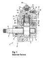
- a high-pressure pump 1 for a fuel injection device of an internal combustion engine is shown.
- the high-pressure pump 1 has a housing 2, which is designed in several parts and in which a drive shaft 3 driven in rotation is arranged.
- the drive shaft 3 is rotatably supported in the housing 2 via two spaced apart in the direction of the axis of rotation 4 of the drive shaft 3 bearings.
- the bearings can be arranged in different housing parts 5, 6 of the housing 2.
- the drive shaft 3 has at least one cam 7 or eccentric, wherein the cam 7 can also be designed as a multiple cam.
- the high-pressure pump 1 has at least one or more arranged in each case 8 a housing part 8 pump elements 9, each with a pump piston 10 which is indirectly driven by the cam 7 of the drive shaft 3 in a lifting movement in at least approximately radial direction to the axis of rotation 4 of the drive shaft 3.
- the pump piston 10 is guided in a cylinder bore 11 in the housing part 8 tightly displaceable and limited with its drive shaft 3 facing away from the end face in the cylinder bore 11 a pump working chamber 12th
- the pump working space 12 has a connection with a fuel feed, for example a feed pump, via a fuel feed channel 13 extending in the housing 2.
- a fuel feed for example a feed pump
- a fuel feed channel 13 extending in the housing 2.
- an opening into the pump chamber 12 inlet valve 14 is arranged, which has a spring-loaded valve member 15.
- the pump working chamber 12 also has a connection extending in the housing part 8 fuel drain passage 16 to an outlet with an outlet, which is connected for example with a high-pressure accumulator 17.
- With the high-pressure accumulator 17 one or more preferably arranged on the cylinders of the internal combustion engine injectors 18 are connected, is injected through the fuel in the cylinder of the internal combustion engine.
- a from the pump working space 12th opening outlet valve 19 is arranged, which also has a spring-loaded valve member 20.
- the pump element 9 is associated with a plunger assembly 21, via which the pump piston 10 is supported on the cam 7 of the drive shaft 3.
- the plunger assembly 21 includes a hollow cylindrical plunger body 22 which is slidably guided in a bore 23 of a portion 5 of the housing 2 of the high-pressure pump 1.
- the pump piston 10 has a smaller diameter than the plunger body 22 and protrudes with its pump chamber 12 facing away from the end of the cylinder bore 11 out and into the plunger body 22 into it.
- the pump piston 10 may have a piston foot 24 which is enlarged in diameter relative to its remaining area.
- the plunger assembly 21 and the pump piston 10 are pressed by a prestressed spring 27 to the cam 7 of the drive shaft 3 out.
- the spring 27 is formed as the pump piston 10 surrounding and projecting into the plunger body 22 helical compression spring.
- the spring 27 is supported on the one hand on the pump housing part 8 and on the other hand on a spring plate 28 from.
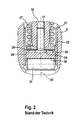
- Fig. 2 shows an in Fig. 1 marked with II section of the plunger assembly 21 of the high-pressure pump 1 of Fig. 1 according to the prior art.
- the spring plate 28 is connected to the pump piston 10 and is located on the side facing away from the roller shoe 26 of the annular web 29 at.
- the spring 27 thus acts on the spring plate 28 both on the pump piston 10 and on the plunger body 22nd
- a roller shoe 26 is inserted in the plunger body 22 of the drive shaft 3 side facing in the direction of the longitudinal axis 25 of the plunger body 22.
- a cylindrical roller 31 is rotatably mounted in a cylinder-section-shaped receptacle 30 on the cam 7 of the drive shaft 3 facing side of the roller shoe 26.
- the roller shoe 26 comes into abutment in the plunger body 22 in the direction of the longitudinal axis 25 against a stop 32 which is formed, for example, by a ring web projecting radially inwards from the plunger body 22.
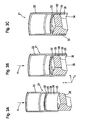
- FIGS. 3A, 3B, 3C each show a section of a plunger assembly 21 according to the prior art before, during and after the press-fitting process.
- FIGS. 4A, 4B, 4C each show a section of a plunger assembly 21 according to an embodiment before, during and after the press-fitting process, wherein the receptacle 30 of the plunger body 22 is provided with a centering guide to be described later.
- Fig. 3A shows an initial stage before the actual press-in process, in which a small force K is applied vertically from above or in the Y direction on the plunger body 22 to bring this into abutment with the roller shoe 26.
- tappet body 22 is at a same in the Y direction on the plunger body 22 applied low force K of the roller shoe 26 already inserted into a first end portion 33 of the receptacle 30 of the plunger body 22.
- a significantly higher pressing force or holding force is present between the plunger body 22 and the roller shoe 26 according to the embodiment than in the corresponding initial stage with respect to the plunger body 22 without centering and the roller shoe 26 according to the prior art.
- Fig. 3B and Fig. 4B show a state during the actual press-fitting process, in which a significantly higher force K of 6 kN in the Y-direction is applied to the tappet body 22.
- K a significantly higher force
- the roller shoe 26 is inserted or pressed along an inner circumference 34 of the receptacle 30 of the plunger body 22 until the roller shoe 26 against the stop 32, which at a second end portion 35 of the receptacle 30 is provided, strikes.
- Fig. 3C and 4C shown a state in which the roller shoe 26 has been pressed into the receptacle 30 of the plunger body 22 and no further force in the Y direction is exerted on the plunger body 22.
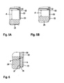
- Fig. 5A again shows a detailed view of the in Fig. 3A illustrated initial stage, in which the plunger body 22 with the roller shoe 26 by low Force is brought into plant.
- a distance d between the stop 32 at the second end portion 35 of the receptacle 30 and the first end portion 33 is 11.8 mm.
- Fig. 5B is shown in the corresponding initial stage of the press-fitting operation of a roller shoe 26 in a provided with a centering tappet body 22 according to the embodiment (see Fig. 4A
- the distance d has already been reduced to 7.8 mm, with the same force K being applied to the tappet body 22 as in FIG Fig. 5A shown installation state.
- Fig. 6 shows a more detailed view of the in Fig. 5B illustrated installation state.
- a centering guide 37 is formed on the inner periphery 34 over a height h of the receptacle 30 of 4 mm.
- the provided on the inner circumference 34 centering guide has a chamfer a of 0.05 mm and an angle of 45 °, which allows the roller shoe 26, already introduced during the initial stage on the height h of the centering guide 37 in the receptacle 30 to be (see Fig. 4A . 5B ).
- a robust plunger assembly 21 or a robust high-pressure pump 1 can be created. Due to the dimensions of the centering guide 37 causes no adverse weakening of the plunger body. Also, the behavior between the plunger body and the roller shoe with respect to the axial distance therebetween or with respect to the radial deformation of the plunger body in an initial stage, during Einpressvorgang itself or during the subsequent discharge is not adversely affected compared to a plunger body-roller shoe press assembly without centering according to the State of the art.
Description
Die vorliegende Erfindung betrifft eine Hochdruckpumpe für eine Kraftstoffeinspritzeinrichtung einer Brennkraftmaschine gemäß dem Oberbegriff des Anspruches 1 und eine Stößelbaugruppe für eine Hochdruckpumpe gemäß dem Oberbegriff des Anspruchs 10.The present invention relates to a high pressure pump for a fuel injection device of an internal combustion engine according to the preamble of claim 1 and a plunger assembly for a high pressure pump according to the preamble of
Hochdruckpumpen für Kraftstoffeinspritzeinrichtungen von Brennkraftmaschinen sind im Stand der Technik bekannt, die eine Stößelbaugruppe mit in einen Stößelkörper eingepressten Rollenschuh aufweisen. Dabei wird die Stößelbaugruppe durch eine rotierend angetriebene Antriebswelle der Hochdruckpumpe beispielsweise gegen die Kraft einer Rückstellfeder in einer Hubbewegung angetrieben.High-pressure pumps for fuel injectors of internal combustion engines are known in the prior art, which have a plunger assembly with pressed into a plunger body roller shoe. In this case, the plunger assembly is driven by a rotationally driven drive shaft of the high pressure pump, for example, against the force of a return spring in a lifting movement.
In
Da die Stößelgruppe vor allem senkrecht zur Drehachse der Rolle und der Antriebswelle wirkende seitliche Kräfte sicher aufnehmen muss, müssen sämtliche Bauteile mit sehr geringen Fertigungstoleranzen ausgeführt werden.Since the ram group must take up especially acting perpendicular to the axis of rotation of the roller and the drive shaft lateral forces safely, all components must be performed with very low manufacturing tolerances.
Aufgrund der erforderlichen Toleranzen der Stößelbaugruppe kommt es jedoch bei der Einpressung des Rollenschuhs in den Stößelkörper oft zu einer Schrägeinpressung. Dies führt wiederum zu nachteiligen bzw. falschen Einpress- bzw. Haltekräften des Pressverbandes bestehend aus Rollenschuh und Stößelkörper.Due to the required tolerances of the plunger assembly, however, it often comes with the press-fitting of the roller shoe in the plunger body to a Schrägeinpressung. This in turn leads to disadvantageous or incorrect press-in or holding forces of the press fit consisting of roller shoe and plunger body.
Daher ist es erforderlich, eine Hochdruckpumpe mit einer Stößelbaugruppe vorzusehen, welche einen robusten Stößelbaugruppen-Pressverband aufweist, bei welchem eine exakte und verbesserte Einpressung des Rollenschuhs in den Stößelkörper gewährleistet ist.Therefore, it is necessary to provide a high-pressure pump with a plunger assembly having a robust ram assembly interference fit in which an accurate and improved press-fitting of the roller shoe is ensured in the plunger body.
Erfindungsgemäß wird eine Hochdruckpumpe für eine Kraftstoffeinspritzeinrichtung einer Brennkraftmaschine vorgesehen, welche mindestens ein Pumpenelement mit einem einen Pumpenarbeitsraum begrenzenden Pumpenkolben aufweist, wobei zwischen dem Pumpenkolben und einer rotierend angetriebenen Antriebswelle der Hochdruckpumpe eine Stößelbaugruppe mit einem Stößelkörper und einem in eine Aufnahme des Stößelkörpers eingepressten Rollenschuh vorgesehen ist, wobei der Stößelkörper eine Zentrierführung zum Einpressen des Rollenschuhs aufweist. Durch das erfindungsgemäße Vorsehen der Zentrierführung wird eine verbesserte Einpressung des Rollenschuhs in den Stößelkörper ermöglicht. Eine Schrägeinpressung wird vermieden, durch die Zentrierführung wird eine automatische Zentrierung erreicht, und dadurch wird ein robuster Stößelbaugruppen-Pressverband geschaffen. Darüber hinaus werden die Einpresskräfte, wenn der Stößelkörper mit einer Zentrierführung versehen wird, nicht verfälscht.According to the invention, a high-pressure pump is provided for a fuel injection device of an internal combustion engine, which has at least one pump element with a pump piston defining a pump chamber, wherein between the pump piston and a drive shaft of the high-pressure pump driven in rotation, a plunger assembly is provided with a plunger body and a pressed into a receptacle of the plunger body roller shoe wherein the plunger body has a centering guide for pressing the roller shoe. The provision according to the invention of the centering guide enables an improved press-fitting of the roller shoe into the tappet body. A Schräginpressung is avoided, the centering an automatic centering is achieved, and thereby a robust ram assembly interference fit is created. In addition, the press-in forces, if the plunger body is provided with a centering, not distorted.
Vorzugsweise ist die Zentrierführung in dem Bereich der Aufnahme vorgesehen.Preferably, the centering guide is provided in the region of the receptacle.
Gemäß einer weiteren bevorzugten Ausführungsform ist die Aufnahme zylinderabschnittsförmig, wobei die Aufnahme einen inneren Umfang aufweist, an welchem die Zentrierführung vorgesehen ist.According to a further preferred embodiment, the receptacle is cylindrical section-shaped, wherein the receptacle has an inner circumference, on which the centering guide is provided.
Gemäß noch einer weiteren bevorzugten Ausführungsform weist die Zentrierführung eine Fase auf.According to yet another preferred embodiment, the centering guide on a chamfer.
Vorzugsweise weist die Aufnahme einen ersten Endabschnitt und einen zweiten Endabschnitt auf, wobei an dem zweiten Endabschnitt ein radial von dem inneren Umfang nach innen abragender Anschlag bzw. Vorsprung vorgesehen ist, und wobei der erste Endabschnitt einem Element der Antriebswelle, insbesondere einem Nocken oder einem Exzenter, gegenüberliegt.Preferably, the receptacle has a first end portion and a second end portion, wherein at the second end portion a radially projecting from the inner periphery inwardly abragender stop or projection is provided, and wherein the first end portion of an element of the drive shaft, in particular a cam or an eccentric , is opposite.
Noch bevorzugter ist die Zentrierführung an dem ersten Endabschnitt vorgesehen.More preferably, the centering guide is provided at the first end portion.
Gemäß einer weiteren bevorzugten Ausführungsform ist die Zentrierführung über eine Höhe des ersten Endabschnitts in einem Bereich von 2 bis 10 mm, insbesondere von 4 mm vorgesehen.According to a further preferred embodiment, the centering guide is provided over a height of the first end portion in a range of 2 to 10 mm, in particular 4 mm.
Es ist darüber hinaus bevorzugt, wenn die Fase eine Tiefe a in dem Bereich von 0,1 bis 0,01 mm, insbesondere von 0,05 mm aufweist, und in einem Winkelbereich von 30 bis 60°, insbesondere mit einem Winkel von 45° ausgebildet ist. Eine Schwächung des Stößelkörpers durch eine Zentrierführung mit den obigen Maßen bzw. in den obigen Abmessungsbereichen hat keine nachteiligen Auswirkungen auf den Stößelbaugruppen-Pressverband. Weder der axiale Abstand zwischen dem Stößelkörper und dem Rollenschuh wird bei der Stößelbaugruppe beim Einpressen bzw. bei einer Druckentlastung nach dem Einpressen im Vergleich zu einer Stößelbaugruppe ohne Zentrierführung negativ beeinflusst, noch wirkt sich eine Zentrierführung mit den oben angegebenen Abmessungen auf die radiale Verformung des Stößelkörpers während des Einpressens und bei anschließender Druckentlastung negativ aus. Vielmehr ergibt sich hinsichtlich des Stößelkörpers mit Zentrierführung eine günstigere Verformung des Stößelkörpers.It is furthermore preferred if the chamfer has a depth a in the range of 0.1 to 0.01 mm, in particular of 0.05 mm, and in an angle range of 30 to 60 °, in particular with an angle of 45 ° is trained. A weakening of the plunger body by a centering guide with the above dimensions or in the above dimensional ranges has no adverse effects on the ram assembly interference fit. Neither the axial distance between the plunger body and the roller shoe is negatively affected in the plunger assembly during insertion or a pressure relief after pressing compared to a plunger assembly without centering, still affects a centering with the dimensions given above on the radial deformation of the plunger body during the pressing in and subsequent pressure relief negative. Rather, arises in terms of Plunger body with centering a more favorable deformation of the plunger body.
Vorzugsweise ist der Rollenschuh mit einem zylindrischen Pressübermaß ausgebildet, welches insbesondere einen Wert Pü,nenn von 9 µm aufweist.Preferably, the roller shoe is formed with a cylindrical excess pressure, which in particular has a value P ü, nenn of 9 microns.
Erfindungsgemäß wird darüber hinaus eine Stößelbaugruppe für eine Hochdruckpumpe für eine Kraftstoffeinspritzeinrichtung einer Brennkraftmaschine, mit einem Stößelkörper und einem in eine Aufnahme des Stößelkörpers eingepressten Rollenschuh vorgesehen, wobei der Stößelkörper eine Zentrierführung zum Einpressen des Rollenschuhs aufweist. Die Stößelbaugruppe ist durch Vorsehen der Zentrierführung robust und weist die oben bereits beschriebenen Vorteile auf.According to the invention, a plunger assembly for a high-pressure pump for a fuel injector of an internal combustion engine, with a plunger body and a pressed into a receptacle of the plunger body roller shoe is also provided, wherein the plunger body has a centering for pressing in the roller shoe. The plunger assembly is robust by providing the centering guide and has the advantages already described above.
Im Nachfolgenden werden Ausführungsbeispiele der Erfindung unter Bezugnahme auf die beigefügten Zeichnungen näher beschrieben. Es zeigt:
- Fig. 1
- einen Längsschnitt durch eine Hochdruckpumpe gemäß dem Stand der Technik;
- Fig. 2
- einen Ausschnitt II oder Stößelbaugruppe der Hochdruckpumpe von
Fig. 1 ; - Fig. 3A, 3B, 3C
- jeweils einen Ausschnitt einer Stößelbaugruppe gemäß dem Stand der Technik vor, beim und nach dem Einpressvorgang;
- Fig. 4A, 4B, 4C
- jeweils einen Ausschnitt einer Stößelbaugruppe gemäß einer Ausführungsform vor, beim und nach dem Einpressvorgang;
- Fig. 5A
- eine Detailansicht des in
Fig. 3A gezeigten Einbauzustands; - Fig. 5B
- eine Detailansicht des in
Fig. 4A gezeigten Einbauzustands; und - Fig. 6
- eine weitere Detailansicht des in
Fig. 5B gezeigten Einbauzustands.
- Fig. 1
- a longitudinal section through a high-pressure pump according to the prior art;
- Fig. 2
- a section II or plunger assembly of the high pressure pump of
Fig. 1 ; - FIGS. 3A, 3B, 3C
- in each case a section of a plunger assembly according to the prior art before, during and after the pressing-in process;
- FIGS. 4A, 4B, 4C
- in each case a section of a plunger assembly according to an embodiment before, during and after the pressing-in process;
- Fig. 5A
- a detailed view of the in
Fig. 3A shown installation state; - Fig. 5B
- a detailed view of the in
Fig. 4A shown installation state; and - Fig. 6
- another detail view of the in
Fig. 5B shown installation state.
In
In einem zwischen den beiden Lagerstellen liegenden Bereich weist die Antriebswelle 3 wenigstens einen Nocken 7 oder Exzenter auf, wobei der Nocken 7 auch als Mehrfachnocken ausgebildet sein kann. Die Hochdruckpumpe 1 weist wenigstens ein oder mehrere in jeweils einem Gehäuseteil 8 angeordnete Pumpenelemente 9 mit jeweils einem Pumpenkolben 10 auf, der durch den Nocken 7 der Antriebswelle 3 mittelbar in einer Hubbewegung in zumindest annähernd radialer Richtung zur Drehachse 4 der Antriebswelle 3 angetrieben wird. Der Pumpenkolben 10 ist in einer Zylinderbohrung 11 im Gehäuseteil 8 dicht verschiebbar geführt und begrenzt mit seiner der Antriebswelle 3 abgewandten Stirnseite in der Zylinderbohrung 11 einen Pumpenarbeitsraum 12.In a region lying between the two bearing points, the drive shaft 3 has at least one cam 7 or eccentric, wherein the cam 7 can also be designed as a multiple cam. The high-pressure pump 1 has at least one or more arranged in each case 8 a
Der Pumpenarbeitsraum 12 weist über einen im Gehäuse 2 verlaufenden Kraftstoffzulaufkanal 13 eine Verbindung mit einem Kraftstoffzulauf beispielsweise einer Förderpumpe auf. An der Mündung des Kraftstoffzulaufkanals 13 in den Pumpenarbeitsraum 12 ist ein in den Pumpenarbeitsraum 12 öffnendes Einlassventil 14 angeordnet, das ein federbelastetes Ventilglied 15 aufweist. Der Pumpenarbeitsraum 12 weist außerdem über einen im Gehäuseteil 8 verlaufenden Kraftstoffablaufkanal 16 eine Verbindung mit einem Auslass auf, der beispielsweise mit einem Hochdruckspeicher 17 verbunden ist. Mit dem Hochdruckspeicher 17 sind ein oder vorzugsweise mehrere an den Zylindern der Brennkraftmaschine angeordnete Injektoren 18 verbunden, durch die Kraftstoff in die Zylinder der Brennkraftmaschine eingespritzt wird. An der Mündung des Kraftstoffablaufkanals 16 in den Pumpenarbeitsraum 12 ist ein aus dem Pumpenarbeitsraum 12 öffnendes Auslassventil 19 angeordnet, das ebenfalls ein federbelastetes Ventilglied 20 aufweist.The
Dem Pumpenelement 9 ist eine Stößelbaugruppe 21 zugeordnet, über die sich der Pumpenkolben 10 am Nocken 7 der Antriebswelle 3 abstützt. Die Stößelbaugruppe 21 umfasst einen hohlzylindrischen Stößelkörper 22, der in einer Bohrung 23 eines Teils 5 des Gehäuses 2 der Hochdruckpumpe 1 verschiebbar geführt ist. Der Pumpenkolben 10 weist einen kleineren Durchmesser auf als der Stößelkörper 22 und ragt mit seinem dem Pumpenarbeitsraum 12 abgewandten Endbereich aus der Zylinderbohrung 11 heraus und in den Stößelkörper 22 hinein. An seinem dem Pumpenarbeitsraum 12 abgewandten Ende kann der Pumpenkolben 10 einen im Durchmesser gegenüber seinem übrigen Bereich vergrösserten Kolbenfuß 24 aufweisen.The pump element 9 is associated with a
Die Stößelbaugruppe 21 und der Pumpenkolben 10 werden durch eine vorgespannte Feder 27 zum Nocken 7 der Antriebswelle 3 hin gedrückt. Die Feder 27 ist als den Pumpenkolben 10 umgebende und in den Stößelkörper 22 hineinragende Schraubendruckfeder ausgebildet. Die Feder 27 stützt sich einerseits am Pumpengehäuseteil 8 und andererseits an einem Federteller 28 ab.The
In den Stößelkörper 22 ist von dessen der Antriebswelle 3 zugewandter Seite her in Richtung der Längsachse 25 des Stößelkörpers 22 ein Rollenschuh 26 eingefügt. Im Rollenschuh 26 ist in einer zylinderabschnittförmigen Aufnahme 30 auf der dem Nocken 7 der Antriebswelle 3 zugewandten Seite des Rollenschuhs 26 eine zylindrische Rolle 31 drehbar gelagert. Der Rollenschuh 26 kommt im Stößelkörper 22 in Richtung der Längsachse 25 an einem Anschlag 32 zur Anlage, der beispielsweise durch einen vom Stößelkörper 22 radial nach innen hervorstehenden Ringsteg gebildet ist.In the
Insgesamt betrachtet kann durch Vorsehen der Zentrierführung 37 eine robuste Stößelbaugruppe 21 bzw. eine robuste Hochdruckpumpe 1 geschaffen werden. Durch die Abmessungen der Zentrierführung 37 keine nachteilige Schwächung des Stößelkörpers verursacht. Auch das Verhalten zwischen dem Stößelkörper und dem Rollenschuh bezüglich des axialen Abstands dazwischen oder bezüglich der radialen Verformung des Stößelkörpers in einem Anfangsstadium, beim Einpressvorgang selbst oder bei der anschließenden Entlastung wird nicht negativ beeinflusst im Vergleich zu einem Stößelkörper-Rollenschuh-Pressverbund ohne Zentrierführung gemäß dem Stand der Technik.Overall, by providing the centering
Claims (10)
- High-pressure pump (1) for a fuel injection device of an internal combustion engine, which high-pressure pump has at least one pump element (9) with a pump piston (10) which delimits a pump working chamber (12), wherein a tappet assembly (21) having a tappet body (22) and having a roller shoe (26) pressed into a receptacle (30) of the tappet body (22) is provided between the pump piston (10) and a drive shaft (3), which is driven in rotation, of the high-pressure pump (1),
characterized in that
the tappet body (22) has a centering guide (37) for the pressing-in of the roller shoe (26). - High-pressure pump (1) according to Claim 1,
characterized in that
the centering guide (37) is provided in the region of the receptacle (30). - High-pressure pump according to Claim 1 or 2,
characterized in that
the receptacle (30) is formed in the shape of a segment of a cylinder, wherein the receptacle (30) has an inner circumference (34) on which the centering guide (37) is provided. - High-pressure pump (1) according to one or more of Claims 1 to 3,
characterized in that
the centering guide (37) has a bevel. - High-pressure pump (1) according to one or more of Claims 1 to 4,
characterized in that
the receptacle (30) has a first end section (33) and a second end section (35), wherein a stop (32) is provided on the second end section (35) so as to project radially inwardly from the inner circumference (34) of the latter, and wherein the first end section (33) faces an element of the drive shaft (3), in particular a cam (7) or an eccentric. - High-pressure pump (1) according to Claim 5,
characterized in that
the centering guide (37) is provided on the first end section (33). - High-pressure pump (1) according to Claim 5 or 6,
characterized in that
the centering guide (37) is provided over a height h of the first end section (33) in a range of 2 to 10 mm, in particular of 4 mm. - High-pressure pump (1) according to one or more of Claims 4 to 7,
characterized in that
the bevel has a depth a in a range of 0.1 to 0.01 mm, in particular a depth a of 0.05 mm, and is formed in an angle range from 30 to 60°, in particular with an angle of 45°. - High-pressure pump (1) according to one or more of Claims 1 to 8,
characterized in that
the roller shoe (26) is formed with a cylindrical interference fit oversize Pü,nenn, in particular with a cylindrical interference fit oversize Pü,nenn of 9 µm. - Tappet assembly (21) for a high-pressure pump (1) for a fuel injection device of an internal combustion engine, having a tappet body (22) and having a roller shoe (26) which is pressed into a receptacle (30) of the tappet body (22),
characterized in that
the tappet body (22) has a centering guide (37) for the pressing-in of the roller shoe (26).
Priority Applications (1)
| Application Number | Priority Date | Filing Date | Title |
|---|---|---|---|
| PL10700440T PL2409014T3 (en) | 2009-03-18 | 2010-01-20 | High pressure pump and tappet assembly |
Applications Claiming Priority (2)
| Application Number | Priority Date | Filing Date | Title |
|---|---|---|---|
| DE102009001631A DE102009001631A1 (en) | 2009-03-18 | 2009-03-18 | High pressure pump and plunger assembly |
| PCT/EP2010/050612 WO2010105863A1 (en) | 2009-03-18 | 2010-01-20 | High pressure pump and tappet assembly |
Publications (2)
| Publication Number | Publication Date |
|---|---|
| EP2409014A1 EP2409014A1 (en) | 2012-01-25 |
| EP2409014B1 true EP2409014B1 (en) | 2013-05-01 |
Family
ID=42121024
Family Applications (1)
| Application Number | Title | Priority Date | Filing Date |
|---|---|---|---|
| EP10700440.0A Active EP2409014B1 (en) | 2009-03-18 | 2010-01-20 | High pressure pump and tappet assembly |
Country Status (11)
| Country | Link |
|---|---|
| US (1) | US20120080013A1 (en) |
| EP (1) | EP2409014B1 (en) |
| JP (1) | JP5497883B2 (en) |
| KR (1) | KR101673636B1 (en) |
| CN (1) | CN102356228B (en) |
| BR (1) | BRPI1013884B1 (en) |
| DE (1) | DE102009001631A1 (en) |
| ES (1) | ES2407864T3 (en) |
| PL (1) | PL2409014T3 (en) |
| RU (1) | RU2524476C2 (en) |
| WO (1) | WO2010105863A1 (en) |
Families Citing this family (9)
| Publication number | Priority date | Publication date | Assignee | Title |
|---|---|---|---|---|
| DE102011002814A1 (en) * | 2011-01-18 | 2012-07-19 | Robert Bosch Gmbh | roller plunger |
| DE102011003678A1 (en) * | 2011-02-07 | 2012-08-09 | Robert Bosch Gmbh | high pressure pump |
| JP5472340B2 (en) * | 2012-02-10 | 2014-04-16 | 株式会社デンソー | Fuel supply pump |
| DE102012211113A1 (en) * | 2012-06-28 | 2014-01-02 | Schaeffler Technologies AG & Co. KG | tappet |
| EP3173612B1 (en) * | 2015-11-24 | 2019-09-18 | Aktiebolaget SKF | Cam follower roller device with retaining plug |
| EP3443205B1 (en) * | 2016-04-15 | 2020-03-04 | Koyo Bearings North America LLC | Tappet with inner cup received on pallet |
| DE102016219046A1 (en) | 2016-09-30 | 2018-04-05 | Robert Bosch Gmbh | Plunger assembly for a radial piston pump, radial piston pump |
| RU202059U1 (en) * | 2020-09-18 | 2021-01-28 | Общество с ограниченной ответственностью Управляющая компания "Алтайский завод прецизионных изделий" | FUEL INJECTION PUMP |
| RU207469U1 (en) * | 2021-07-19 | 2021-10-28 | Общество с ограниченной ответственностью Управляющая компания "Алтайский завод прецизионных изделий" | HIGH PRESSURE FUEL PUMP PUSH |
Family Cites Families (14)
| Publication number | Priority date | Publication date | Assignee | Title |
|---|---|---|---|---|
| SU109119A1 (en) * | 1957-02-25 | 1957-11-30 | П.И. Андрусенко | Radial Plunger Fuel Pump |
| FR2567577B1 (en) * | 1984-07-12 | 1989-03-03 | Cav Roto Diesel | IMPROVEMENTS ON FUEL INJECTION PUMPS FOR INTERNAL COMBUSTION ENGINES |
| JP2584333Y2 (en) * | 1990-03-12 | 1998-10-30 | 光洋精工株式会社 | Cam follower device |
| JP2584333B2 (en) * | 1990-04-04 | 1997-02-26 | 三洋電機株式会社 | Acoustic equipment having disc playback device |
| US5361733A (en) * | 1993-01-28 | 1994-11-08 | General Motors Corporation | Compact valve lifters |
| RU2079695C1 (en) * | 1994-06-22 | 1997-05-20 | Михаил Григорьевич Сандомирский | Fuel pump |
| JP3693992B2 (en) * | 2002-11-08 | 2005-09-14 | 三菱電機株式会社 | High pressure fuel pump |
| US20050100466A1 (en) * | 2003-01-09 | 2005-05-12 | Nobuo Aoki | Fuel supply pump |
| JP2004324537A (en) * | 2003-04-24 | 2004-11-18 | Bosch Automotive Systems Corp | Pump for fuel supply and tappet structure |
| DE10345061A1 (en) | 2003-09-26 | 2005-04-14 | Robert Bosch Gmbh | Plunger assembly for a high pressure pump and high pressure pump with at least one plunger assembly |
| RU45479U1 (en) * | 2004-12-28 | 2005-05-10 | Государственное образовательное учреждение высшего профессионального образования "Алтайский государственный технический университет им. И.И. Ползунова" (АлтГТУ) | CAM MECHANISM FOR DRIVING THE DIESEL ENGINE HIGH PRESSURE FUEL PUMP PLUNG DRIVE |
| DE102006041673A1 (en) * | 2006-02-20 | 2007-08-23 | Robert Bosch Gmbh | High pressure pump especially for fuel injection in IC engine has the cam follower supported axially by hardened low wear surfaces |
| CN201025197Y (en) * | 2007-04-23 | 2008-02-20 | 无锡威孚集团有限公司 | A mandatory lubricant roller pole for high-pressure common-rail pump |
| CN101280753A (en) * | 2008-05-19 | 2008-10-08 | 宁波中策动力机电集团有限公司 | Diesel engine oil jetting pump post rod parts |
-
2009
- 2009-03-18 DE DE102009001631A patent/DE102009001631A1/en not_active Withdrawn
-
2010
- 2010-01-20 PL PL10700440T patent/PL2409014T3/en unknown
- 2010-01-20 ES ES10700440T patent/ES2407864T3/en active Active
- 2010-01-20 BR BRPI1013884-6A patent/BRPI1013884B1/en not_active IP Right Cessation
- 2010-01-20 RU RU2011141885/06A patent/RU2524476C2/en active
- 2010-01-20 WO PCT/EP2010/050612 patent/WO2010105863A1/en active Application Filing
- 2010-01-20 US US13/257,360 patent/US20120080013A1/en not_active Abandoned
- 2010-01-20 JP JP2012500160A patent/JP5497883B2/en active Active
- 2010-01-20 EP EP10700440.0A patent/EP2409014B1/en active Active
- 2010-01-20 CN CN201080012426.9A patent/CN102356228B/en not_active Expired - Fee Related
- 2010-01-20 KR KR1020117021571A patent/KR101673636B1/en active IP Right Grant
Also Published As
| Publication number | Publication date |
|---|---|
| RU2011141885A (en) | 2013-04-27 |
| CN102356228A (en) | 2012-02-15 |
| BRPI1013884A2 (en) | 2016-04-05 |
| ES2407864T3 (en) | 2013-06-14 |
| EP2409014A1 (en) | 2012-01-25 |
| RU2524476C2 (en) | 2014-07-27 |
| KR20110132567A (en) | 2011-12-08 |
| WO2010105863A1 (en) | 2010-09-23 |
| US20120080013A1 (en) | 2012-04-05 |
| BRPI1013884B1 (en) | 2020-08-18 |
| JP2012520423A (en) | 2012-09-06 |
| DE102009001631A1 (en) | 2010-09-23 |
| JP5497883B2 (en) | 2014-05-21 |
| CN102356228B (en) | 2014-07-09 |
| PL2409014T3 (en) | 2013-09-30 |
| KR101673636B1 (en) | 2016-11-07 |
Similar Documents
| Publication | Publication Date | Title |
|---|---|---|
| EP2409014B1 (en) | High pressure pump and tappet assembly | |
| EP2076669B1 (en) | Tappet assembly for a high-pressure pump and high-pressure pump comprising at least one tappet assembly | |
| DE10355027A1 (en) | High-pressure pump, in particular for a fuel injection device of an internal combustion engine | |
| EP2464866B1 (en) | High pressure pump | |
| EP2522854A1 (en) | Valve assembly for a high pressure fuel pump and high pressure fuel pump | |
| WO2005031151A1 (en) | Tappet for a high-pressure pump and high-pressure pump comprising at least one tappet | |
| DE102008001890A1 (en) | High-pressure pump i.e. radial or tandem piston pump, for fuel i.e. diesel, injection system of air compressed, self ignition internal combustion engine, has aligning element for aligning tappet body in orientation at area | |
| DE10345061A1 (en) | Plunger assembly for a high pressure pump and high pressure pump with at least one plunger assembly | |
| DE102009001633A1 (en) | High-pressure pump for fuel injection device of internal-combustion engine, has roller shoe comprising cylindrical pressing interference of specific value at section of circumference surface of roller shoe | |
| DE10141679A1 (en) | Fuel injection device for an internal combustion engine | |
| DE102010041178A1 (en) | Pump i.e. high-pressure fuel pump, for fuel injector of internal combustion engine, has roller comprising central portion and edge areas in direction of axis of shaft, where portion and areas are longitudinally formed away from track | |
| DE102008008438A1 (en) | High-pressure pump has tappet, which serves for indirect support of piston with longitudinal axis at drive shaft over roller, which is pivotally coupled with tappet | |
| EP3387247B1 (en) | Electromagnetically actuatable inlet valve and high-pressure pump having an inlet valve | |
| DE102015218754B4 (en) | high pressure pump | |
| DE10352024A1 (en) | Solenoid valve | |
| EP2596231B1 (en) | Fuel injector having a hydraulic coupler unit | |
| DE10355028A1 (en) | High pressure pump especially for vehicle has the piston rod and cam follower made in one piece and spring loaded to press onto the drive cam | |
| WO2016142072A1 (en) | High-pressure fuel pump, in particular for a fuel injection device of an internal combustion engine | |
| DE102014211469A1 (en) | Nozzle assembly for a fuel injector and fuel injector | |
| WO2023057251A1 (en) | High-pressure fuel pump for a fuel system of an internal combustion engine | |
| WO2023036646A1 (en) | Cyclically operating pump, in particular high-pressure fuel piston pump | |
| DE102022205476A1 (en) | Piston pump, in particular high-pressure fuel pump for a fuel system of an internal combustion engine | |
| DE102020214037A1 (en) | High pressure fuel pump | |
| DE102016210842A1 (en) | piston pump | |
| DE102019220585A1 (en) | High pressure fuel pump |
Legal Events
| Date | Code | Title | Description |
|---|---|---|---|
| PUAI | Public reference made under article 153(3) epc to a published international application that has entered the european phase |
Free format text: ORIGINAL CODE: 0009012 |
|
| 17P | Request for examination filed |
Effective date: 20111018 |
|
| AK | Designated contracting states |
Kind code of ref document: A1 Designated state(s): AT BE BG CH CY CZ DE DK EE ES FI FR GB GR HR HU IE IS IT LI LT LU LV MC MK MT NL NO PL PT RO SE SI SK SM TR |
|
| DAX | Request for extension of the european patent (deleted) | ||
| GRAP | Despatch of communication of intention to grant a patent |
Free format text: ORIGINAL CODE: EPIDOSNIGR1 |
|
| GRAS | Grant fee paid |
Free format text: ORIGINAL CODE: EPIDOSNIGR3 |
|
| GRAA | (expected) grant |
Free format text: ORIGINAL CODE: 0009210 |
|
| AK | Designated contracting states |
Kind code of ref document: B1 Designated state(s): AT BE BG CH CY CZ DE DK EE ES FI FR GB GR HR HU IE IS IT LI LT LU LV MC MK MT NL NO PL PT RO SE SI SK SM TR |
|
| REG | Reference to a national code |
Ref country code: GB Ref legal event code: FG4D Free format text: NOT ENGLISH |
|
| REG | Reference to a national code |
Ref country code: AT Ref legal event code: REF Ref document number: 610105 Country of ref document: AT Kind code of ref document: T Effective date: 20130515 Ref country code: CH Ref legal event code: EP |
|
| REG | Reference to a national code |
Ref country code: IE Ref legal event code: FG4D Free format text: LANGUAGE OF EP DOCUMENT: GERMAN |
|
| REG | Reference to a national code |
Ref country code: ES Ref legal event code: FG2A Ref document number: 2407864 Country of ref document: ES Kind code of ref document: T3 Effective date: 20130614 |
|
| REG | Reference to a national code |
Ref country code: DE Ref legal event code: R096 Ref document number: 502010003139 Country of ref document: DE Effective date: 20130627 |
|
| REG | Reference to a national code |
Ref country code: SE Ref legal event code: TRGR |
|
| REG | Reference to a national code |
Ref country code: PL Ref legal event code: T3 |
|
| REG | Reference to a national code |
Ref country code: NL Ref legal event code: VDEP Effective date: 20130501 |
|
| REG | Reference to a national code |
Ref country code: LT Ref legal event code: MG4D |
|
| PG25 | Lapsed in a contracting state [announced via postgrant information from national office to epo] |
Ref country code: LT Free format text: LAPSE BECAUSE OF FAILURE TO SUBMIT A TRANSLATION OF THE DESCRIPTION OR TO PAY THE FEE WITHIN THE PRESCRIBED TIME-LIMIT Effective date: 20130501 Ref country code: PT Free format text: LAPSE BECAUSE OF FAILURE TO SUBMIT A TRANSLATION OF THE DESCRIPTION OR TO PAY THE FEE WITHIN THE PRESCRIBED TIME-LIMIT Effective date: 20130902 Ref country code: NO Free format text: LAPSE BECAUSE OF FAILURE TO SUBMIT A TRANSLATION OF THE DESCRIPTION OR TO PAY THE FEE WITHIN THE PRESCRIBED TIME-LIMIT Effective date: 20130801 Ref country code: IS Free format text: LAPSE BECAUSE OF FAILURE TO SUBMIT A TRANSLATION OF THE DESCRIPTION OR TO PAY THE FEE WITHIN THE PRESCRIBED TIME-LIMIT Effective date: 20130901 Ref country code: SI Free format text: LAPSE BECAUSE OF FAILURE TO SUBMIT A TRANSLATION OF THE DESCRIPTION OR TO PAY THE FEE WITHIN THE PRESCRIBED TIME-LIMIT Effective date: 20130501 Ref country code: GR Free format text: LAPSE BECAUSE OF FAILURE TO SUBMIT A TRANSLATION OF THE DESCRIPTION OR TO PAY THE FEE WITHIN THE PRESCRIBED TIME-LIMIT Effective date: 20130802 Ref country code: FI Free format text: LAPSE BECAUSE OF FAILURE TO SUBMIT A TRANSLATION OF THE DESCRIPTION OR TO PAY THE FEE WITHIN THE PRESCRIBED TIME-LIMIT Effective date: 20130501 |
|
| PG25 | Lapsed in a contracting state [announced via postgrant information from national office to epo] |
Ref country code: HR Free format text: LAPSE BECAUSE OF FAILURE TO SUBMIT A TRANSLATION OF THE DESCRIPTION OR TO PAY THE FEE WITHIN THE PRESCRIBED TIME-LIMIT Effective date: 20130501 Ref country code: CY Free format text: LAPSE BECAUSE OF FAILURE TO SUBMIT A TRANSLATION OF THE DESCRIPTION OR TO PAY THE FEE WITHIN THE PRESCRIBED TIME-LIMIT Effective date: 20130501 Ref country code: BG Free format text: LAPSE BECAUSE OF FAILURE TO SUBMIT A TRANSLATION OF THE DESCRIPTION OR TO PAY THE FEE WITHIN THE PRESCRIBED TIME-LIMIT Effective date: 20130801 |
|
| PG25 | Lapsed in a contracting state [announced via postgrant information from national office to epo] |
Ref country code: LV Free format text: LAPSE BECAUSE OF FAILURE TO SUBMIT A TRANSLATION OF THE DESCRIPTION OR TO PAY THE FEE WITHIN THE PRESCRIBED TIME-LIMIT Effective date: 20130501 |
|
| PG25 | Lapsed in a contracting state [announced via postgrant information from national office to epo] |
Ref country code: DK Free format text: LAPSE BECAUSE OF FAILURE TO SUBMIT A TRANSLATION OF THE DESCRIPTION OR TO PAY THE FEE WITHIN THE PRESCRIBED TIME-LIMIT Effective date: 20130501 Ref country code: SK Free format text: LAPSE BECAUSE OF FAILURE TO SUBMIT A TRANSLATION OF THE DESCRIPTION OR TO PAY THE FEE WITHIN THE PRESCRIBED TIME-LIMIT Effective date: 20130501 Ref country code: EE Free format text: LAPSE BECAUSE OF FAILURE TO SUBMIT A TRANSLATION OF THE DESCRIPTION OR TO PAY THE FEE WITHIN THE PRESCRIBED TIME-LIMIT Effective date: 20130501 |
|
| PG25 | Lapsed in a contracting state [announced via postgrant information from national office to epo] |
Ref country code: NL Free format text: LAPSE BECAUSE OF FAILURE TO SUBMIT A TRANSLATION OF THE DESCRIPTION OR TO PAY THE FEE WITHIN THE PRESCRIBED TIME-LIMIT Effective date: 20130501 Ref country code: RO Free format text: LAPSE BECAUSE OF FAILURE TO SUBMIT A TRANSLATION OF THE DESCRIPTION OR TO PAY THE FEE WITHIN THE PRESCRIBED TIME-LIMIT Effective date: 20130501 |
|
| PLBE | No opposition filed within time limit |
Free format text: ORIGINAL CODE: 0009261 |
|
| STAA | Information on the status of an ep patent application or granted ep patent |
Free format text: STATUS: NO OPPOSITION FILED WITHIN TIME LIMIT |
|
| 26N | No opposition filed |
Effective date: 20140204 |
|
| REG | Reference to a national code |
Ref country code: HU Ref legal event code: AG4A Ref document number: E018719 Country of ref document: HU |
|
| REG | Reference to a national code |
Ref country code: DE Ref legal event code: R097 Ref document number: 502010003139 Country of ref document: DE Effective date: 20140204 |
|
| BERE | Be: lapsed |
Owner name: ROBERT BOSCH G.M.B.H. Effective date: 20140131 |
|
| PG25 | Lapsed in a contracting state [announced via postgrant information from national office to epo] |
Ref country code: LU Free format text: LAPSE BECAUSE OF FAILURE TO SUBMIT A TRANSLATION OF THE DESCRIPTION OR TO PAY THE FEE WITHIN THE PRESCRIBED TIME-LIMIT Effective date: 20140120 |
|
| REG | Reference to a national code |
Ref country code: CH Ref legal event code: PL |
|
| PG25 | Lapsed in a contracting state [announced via postgrant information from national office to epo] |
Ref country code: LI Free format text: LAPSE BECAUSE OF NON-PAYMENT OF DUE FEES Effective date: 20140131 Ref country code: CH Free format text: LAPSE BECAUSE OF NON-PAYMENT OF DUE FEES Effective date: 20140131 |
|
| REG | Reference to a national code |
Ref country code: IE Ref legal event code: MM4A |
|
| PG25 | Lapsed in a contracting state [announced via postgrant information from national office to epo] |
Ref country code: IE Free format text: LAPSE BECAUSE OF NON-PAYMENT OF DUE FEES Effective date: 20140120 Ref country code: BE Free format text: LAPSE BECAUSE OF NON-PAYMENT OF DUE FEES Effective date: 20140131 |
|
| PG25 | Lapsed in a contracting state [announced via postgrant information from national office to epo] |
Ref country code: MC Free format text: LAPSE BECAUSE OF FAILURE TO SUBMIT A TRANSLATION OF THE DESCRIPTION OR TO PAY THE FEE WITHIN THE PRESCRIBED TIME-LIMIT Effective date: 20130501 |
|
| REG | Reference to a national code |
Ref country code: FR Ref legal event code: PLFP Year of fee payment: 7 |
|
| PG25 | Lapsed in a contracting state [announced via postgrant information from national office to epo] |
Ref country code: MT Free format text: LAPSE BECAUSE OF FAILURE TO SUBMIT A TRANSLATION OF THE DESCRIPTION OR TO PAY THE FEE WITHIN THE PRESCRIBED TIME-LIMIT Effective date: 20130501 |
|
| REG | Reference to a national code |
Ref country code: AT Ref legal event code: MM01 Ref document number: 610105 Country of ref document: AT Kind code of ref document: T Effective date: 20150120 |
|
| PG25 | Lapsed in a contracting state [announced via postgrant information from national office to epo] |
Ref country code: SM Free format text: LAPSE BECAUSE OF FAILURE TO SUBMIT A TRANSLATION OF THE DESCRIPTION OR TO PAY THE FEE WITHIN THE PRESCRIBED TIME-LIMIT Effective date: 20130501 |
|
| PG25 | Lapsed in a contracting state [announced via postgrant information from national office to epo] |
Ref country code: AT Free format text: LAPSE BECAUSE OF NON-PAYMENT OF DUE FEES Effective date: 20150120 |
|
| PG25 | Lapsed in a contracting state [announced via postgrant information from national office to epo] |
Ref country code: TR Free format text: LAPSE BECAUSE OF FAILURE TO SUBMIT A TRANSLATION OF THE DESCRIPTION OR TO PAY THE FEE WITHIN THE PRESCRIBED TIME-LIMIT Effective date: 20130501 |
|
| REG | Reference to a national code |
Ref country code: FR Ref legal event code: PLFP Year of fee payment: 8 |
|
| REG | Reference to a national code |
Ref country code: FR Ref legal event code: PLFP Year of fee payment: 9 |
|
| PGFP | Annual fee paid to national office [announced via postgrant information from national office to epo] |
Ref country code: GB Payment date: 20180125 Year of fee payment: 9 Ref country code: ES Payment date: 20180201 Year of fee payment: 9 Ref country code: CZ Payment date: 20180105 Year of fee payment: 9 |
|
| PGFP | Annual fee paid to national office [announced via postgrant information from national office to epo] |
Ref country code: HU Payment date: 20180111 Year of fee payment: 9 Ref country code: SE Payment date: 20180125 Year of fee payment: 9 Ref country code: PL Payment date: 20180111 Year of fee payment: 9 |
|
| PG25 | Lapsed in a contracting state [announced via postgrant information from national office to epo] |
Ref country code: MK Free format text: LAPSE BECAUSE OF FAILURE TO SUBMIT A TRANSLATION OF THE DESCRIPTION OR TO PAY THE FEE WITHIN THE PRESCRIBED TIME-LIMIT Effective date: 20130501 |
|
| GBPC | Gb: european patent ceased through non-payment of renewal fee |
Effective date: 20190120 |
|
| PG25 | Lapsed in a contracting state [announced via postgrant information from national office to epo] |
Ref country code: SE Free format text: LAPSE BECAUSE OF NON-PAYMENT OF DUE FEES Effective date: 20190121 Ref country code: CZ Free format text: LAPSE BECAUSE OF NON-PAYMENT OF DUE FEES Effective date: 20190120 |
|
| PG25 | Lapsed in a contracting state [announced via postgrant information from national office to epo] |
Ref country code: HU Free format text: LAPSE BECAUSE OF NON-PAYMENT OF DUE FEES Effective date: 20190121 |
|
| PG25 | Lapsed in a contracting state [announced via postgrant information from national office to epo] |
Ref country code: GB Free format text: LAPSE BECAUSE OF NON-PAYMENT OF DUE FEES Effective date: 20190120 |
|
| REG | Reference to a national code |
Ref country code: ES Ref legal event code: FD2A Effective date: 20200310 |
|
| PG25 | Lapsed in a contracting state [announced via postgrant information from national office to epo] |
Ref country code: ES Free format text: LAPSE BECAUSE OF NON-PAYMENT OF DUE FEES Effective date: 20190121 |
|
| PG25 | Lapsed in a contracting state [announced via postgrant information from national office to epo] |
Ref country code: PL Free format text: LAPSE BECAUSE OF NON-PAYMENT OF DUE FEES Effective date: 20190120 |
|
| PGFP | Annual fee paid to national office [announced via postgrant information from national office to epo] |
Ref country code: IT Payment date: 20220124 Year of fee payment: 13 Ref country code: FR Payment date: 20220120 Year of fee payment: 13 |
|
| PGFP | Annual fee paid to national office [announced via postgrant information from national office to epo] |
Ref country code: DE Payment date: 20230324 Year of fee payment: 14 |
|
| P01 | Opt-out of the competence of the unified patent court (upc) registered |
Effective date: 20230509 |
|
| PG25 | Lapsed in a contracting state [announced via postgrant information from national office to epo] |
Ref country code: FR Free format text: LAPSE BECAUSE OF NON-PAYMENT OF DUE FEES Effective date: 20230131 |
|
| PG25 | Lapsed in a contracting state [announced via postgrant information from national office to epo] |
Ref country code: IT Free format text: LAPSE BECAUSE OF NON-PAYMENT OF DUE FEES Effective date: 20230120 |