EP1628369A1 - Connecteur électrique avec blindage - Google Patents
Connecteur électrique avec blindage Download PDFInfo
- Publication number
- EP1628369A1 EP1628369A1 EP05016924A EP05016924A EP1628369A1 EP 1628369 A1 EP1628369 A1 EP 1628369A1 EP 05016924 A EP05016924 A EP 05016924A EP 05016924 A EP05016924 A EP 05016924A EP 1628369 A1 EP1628369 A1 EP 1628369A1
- Authority
- EP
- European Patent Office
- Prior art keywords
- section
- connector
- counter
- shield
- attaching
- Prior art date
- Legal status (The legal status is an assumption and is not a legal conclusion. Google has not performed a legal analysis and makes no representation as to the accuracy of the status listed.)
- Withdrawn
Links
Images


Classifications
-
- H—ELECTRICITY
- H01—ELECTRIC ELEMENTS
- H01R—ELECTRICALLY-CONDUCTIVE CONNECTIONS; STRUCTURAL ASSOCIATIONS OF A PLURALITY OF MUTUALLY-INSULATED ELECTRICAL CONNECTING ELEMENTS; COUPLING DEVICES; CURRENT COLLECTORS
- H01R13/00—Details of coupling devices of the kinds covered by groups H01R12/70 or H01R24/00 - H01R33/00
- H01R13/648—Protective earth or shield arrangements on coupling devices, e.g. anti-static shielding
- H01R13/658—High frequency shielding arrangements, e.g. against EMI [Electro-Magnetic Interference] or EMP [Electro-Magnetic Pulse]
- H01R13/6581—Shield structure
- H01R13/6582—Shield structure with resilient means for engaging mating connector
- H01R13/6583—Shield structure with resilient means for engaging mating connector with separate conductive resilient members between mating shield members
-
- H—ELECTRICITY
- H01—ELECTRIC ELEMENTS
- H01R—ELECTRICALLY-CONDUCTIVE CONNECTIONS; STRUCTURAL ASSOCIATIONS OF A PLURALITY OF MUTUALLY-INSULATED ELECTRICAL CONNECTING ELEMENTS; COUPLING DEVICES; CURRENT COLLECTORS
- H01R12/00—Structural associations of a plurality of mutually-insulated electrical connecting elements, specially adapted for printed circuits, e.g. printed circuit boards [PCB], flat or ribbon cables, or like generally planar structures, e.g. terminal strips, terminal blocks; Coupling devices specially adapted for printed circuits, flat or ribbon cables, or like generally planar structures; Terminals specially adapted for contact with, or insertion into, printed circuits, flat or ribbon cables, or like generally planar structures
-
- H—ELECTRICITY
- H01—ELECTRIC ELEMENTS
- H01R—ELECTRICALLY-CONDUCTIVE CONNECTIONS; STRUCTURAL ASSOCIATIONS OF A PLURALITY OF MUTUALLY-INSULATED ELECTRICAL CONNECTING ELEMENTS; COUPLING DEVICES; CURRENT COLLECTORS
- H01R13/00—Details of coupling devices of the kinds covered by groups H01R12/70 or H01R24/00 - H01R33/00
- H01R13/648—Protective earth or shield arrangements on coupling devices, e.g. anti-static shielding
- H01R13/658—High frequency shielding arrangements, e.g. against EMI [Electro-Magnetic Interference] or EMP [Electro-Magnetic Pulse]
- H01R13/6591—Specific features or arrangements of connection of shield to conductive members
- H01R13/6594—Specific features or arrangements of connection of shield to conductive members the shield being mounted on a PCB and connected to conductive members
Definitions
- the present invention relates to an electrical connector having a shield, in which two connectors (a receptacle connector and a plug connector) are respectively shielded and mounted on a different printed circuit board so as to connect those printed circuit boards to each other.
- an electrical connector which connects flat printed circuit boards to each other, is widely used.
- This type of electrical connector is respectively mounted on a different printed circuit board, and comprised of a receptacle connector and a plug connector, which connect to each other. By connecting the receptacle connector with the plug connector, the printed circuit boards are connected to each other.
- the receptacle connector and the plug connector respectively have a connector fitting section on the respective connector housings, and each connector fitting section has a plurality of contact terminals, which are arranged thereon by a specified pitch.
- the contact terminals arranged on the connector housing of the receptacle connector have spring-like characteristics. Once the receptacle connector is connected to the plug connector, the contact terminals arranged on the respective connector housings are electrically connected to each other by contacting through pressure by the spring-like characteristics.
- the above-described receptacle connector and plug connector are connectors having a shield, and a shielding member is attached to the respective connector housings.
- the shielding member of the receptacle connector is comprised of side shielding plates 100, which are attached along both sides of the connector housing in the longitudinal direction of the connector, and end shielding plates 101, which are arranged at both ends of the connector of the connector housing in the lateral direction of the connector.
- the end shielding plates 101 are non-contact shields, which are not connected to the side shielding plates 100.
- the shielding member of the plug connector is described in the patent reference 1.
- the shielding member is comprised of side shielding plates 102, which are attached along both sides of the connector housing (not illustrated) in the longitudinal direction of the connector, and end shielding plates 103, which are arranged on both end surfaces of the connector housing in the lateral direction of the connector.
- Both ends of the end shielding plates 103 are curved, and have contact point sections 105 at the curved sections 104.
- the side shielding plates 100 and 102 in order to attach each of the side shielding plates 100 and 102 to both side surfaces of the connector housing, the side shielding plates 100 and 102 have a inverted U-shaped contact tongue section. By hooking the contact tongue sections to both side surfaces of the connector housing, those side shielding plates are attached to the connector housing.
- the side shielding plates 100 and 102 in order to contact the contact tongue sections with the connector housing, the side shielding plates 100 and 102 have protrusions (not illustrated). In order to generate elastic force to press the protrusions to the connector housing, the side shielding plates 100 and 102 have a windows (not illustrated) near the protrusions.
- Patent Reference Unexamined Japan Patent Application Publication H11-233201
- the side shielding plates 100 are not connected to the end shielding plates 101, and there are unshielded portions between the side shielding plates 100 and the end shielding plates 101. Accordingly, when the receptacle connector is jointed to the plug connector, although the shielding members of the plug connector surround the shielding members of the receptacle connector, there are unshielded portions, and there is a plurality of windows on the side shielding plates 100. Therefore, there are problems such as unstable data transmission or communication error in an electronic device due to noise leakage. Especially, since high-speed signal transmission has been advanced in these years, those problems become more obvious.
- the end shielding plates 103 are provided near the end surfaces of the connector housing. There is some space between the end surface and the connector fitting section, which is not efficiently used and makes difficult to reduce the size of the connector.
- an object of the invention to provide an electrical connector having a shield, whereby problems such as unstable data transmission or communication error in an electronic device due to noise leakage can be solved and smaller electrical connector having a shield can be provided.
- the receptacle connector A which is one connector that composes the electrical connector of this invention, is comprised of a connector housing 1, a number of contact terminals 29 attached to terminal attaching sections 9, which are provided on a connector fitting section 2 of the connector housing 1, and a shielding member 30.
- the connector housing 1 has a convex shape, and is comprised of wall sections 3 and 4 provided along the longitudinal direction of the connector housing 1, and wall sections 6 and 7 provided along the lateral direction of the connector housing 1.
- space 5 is formed being surrounded by the wall sections 3, 4, 6 and 7, and a counter connector fitting section 2 is formed by the outer surfaces of the wall sections 3, 4, 6 and 7.
- Guiding sections 2A are formed at the edges at the outer surface sides of respective wall sections 3, 4, 6 and 7 by beveling.
- Terminal attaching sections 9 are formed by the space between adjacent dividing sections 8. Terminal insertion openings 10 connected to bottoms of the terminal attaching sections 9 are formed at the connector housing 1. End shield attaching sections 12 are provided on the surface of the connector housing 1 at both ends in the longitudinal direction of the connector being close to the ends of the connector fitting sections 2. As shown in Fig.
- each of those end shield attaching sections 12 is comprised of a first end shield insertion groove 13, which has a squared U-shape on its cross-sectional view, and a second end shield insertion groove 14, which is perpendicular to the first end shield insertion groove 13.
- an insertion groove 13a is formed at both side surfaces of the first end shield insertion groove 13 in the connector lateral direction.
- a press-in section 13b is formed in the center part of the first end shield insertion groove 13.
- a side shield attaching section 15 is formed at both side surfaces of the connector housing 1. As shown in Fig. 7, those side shield attaching sections 15 have linear side shield grooves 16 along the longitudinal direction of the connector housing 1.
- a latch insertion groove 17 is formed at the center part of each side shield groove 16 being perpendicular to the side shield groove 16.
- a latching section 18 is formed at the both side surfaces of the connector housing 1 so as to be across the latch insertion groove 17.
- a plurality of insertion grooves 19 is formed so as to be perpendicular to the side shield grooves 16.
- a connecting section (one connecting section) 20 which connects the side shield grooves 16 to the insertion grooves 13a, is formed at the end shield attaching section 12 side of the side shield groove 16.
- Each of those connecting sections 20 is comprised of a groove 21 formed at the backside of the connector housing 1, and insertion hole 22 that connects the groove 21 to the insertion hole 13a.
- each contact terminal 24 is comprised of a attaching section (press-in section) 23, a terminal lead section 24 provided at the end of the attaching section 23, an elasticity providing section 26 that is provided opposite to the terminal lead section and connected to the attaching section 23 via a curved connecting section 25, and a contact section 27 formed at the end of the elasticity providing section 26.
- Each contact terminal 29 is attached to or pressed in the terminal attaching section 9 being inserted from each terminal insertion opening of the connector housing 1. More specifically, each contact terminal 29 is inserted in the terminal attaching section 9 between the dividing sections 8, by pressing therein, so that the terminal lead section 24 protrudes outward from the terminal insertion opening 10, and the contact section 27 faces the center part of the connector fitting section 2.
- the shielding member 30 is comprised of end shields 31 and side shields 40. As shown in Figs. 10-11, each end shield 31 has a main shielding section 32, which has a squared U-shape on its top view. A contact point section (contact section provided on one side) is provided on the outer surface of the curved section 33, which are provided at the both ends of the main shielding section 32. In addition, a shield contact bar 36 is provided at the center part of the main shielding section 32 being curved and parallel to a press-in leg 35. A protrusion 37 is provided on the outer surface of the shielding contact bar 36. Furthermore, a shielding terminal 37A is formed at the end of the shielding contact bar 36. Each side shield 40 has a strip-like main shielding section 41.
- a latch 42 is formed at the center part of the main shielding section 41 being perpendicular to the main shielding section 41.
- a tongue 43 is formed at both sides across the latch 42 of the main shielding section 41 being perpendicular to the main shielding section 41.
- holes 44 are provided at the main shielding section 41 sharing one center axis of the tongue 43 on the side view of the side shield.
- a shield contact bar 45 which is curved to generally have a U-shape, is formed at both ends of the main shielding section 41.
- a contact point contact section 46 is formed at the outer surfaces of the shield contact bars 45.
- a shield terminal 47 is provided at both ends of the main shielding section being perpendicular to the surface of the main shielding section 41.
- the end shield 31 is attached to the end shield attaching section 15 of the connector housing 1. More specifically, the main shielding section 32 is inserted in the first end shield insertion groove 13, and the press-in leg 33 is pressed in the press-in section 13b. At this time, the contact point section 34 of the curved sections 33 on both sides of the main shielding section 32 face the insertion groove 13a of the both side surface of the first end shield insertion groove 13. Each shield terminal 37A and the shielding contact bar 36 are inserted in the latching bar insertion groove 17, and latched in the latching section 18. The tongue 43 of the main shielding section 41 is inserted in the insertion groove 19.
- the shield contact bars 45 on both sides of the main shielding section 41 are inserted in the connecting sections 20 of the side shielding groove 16. More specifically, those shield contact bars 45 are inserted in the insertion grooves 13a of the end shield attaching sections 12 via the insertion hole 22 from the groove 21 of the connecting section 20.
- the contact point contact section 46 of each shield contact bar 45 contacts with the contact point 34 of the end shield 31.
- the end shields 31 and the side shields 40 are connected to each other at those contact points I, and the connector fitting section 2 is surrounded by a pair of end shields 31 and a pair of the side shields 40.
- a positioning pin (not illustrated) provided on the bottom of the connector housing 1 is inserted in a positioning hole (not illustrated) of a printed circuit board.
- the terminal lead section 24 of each contact terminal 29 is soldered to a contact point pattern section by reflow soldering with solder cream, contacting the terminal lead section 24 to solder cream applied on the contact point pattern section (not illustrated) of the printed circuit board.
- respective shielding terminals 37A and 47 are contacted to solder cream applied on the shielding pattern section of the printed circuit board and soldered thereto by reflow soldering.
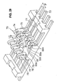
- the plug connector B is comprised of a connector housing 51, a number of contact terminals (counter contact terminals) 70 provided at the connector fitting section (counter connector fitting section) 54 of the connector housing 51, and a shielding member (counter shielding member) 80.
- the connector housing 51 has a concave section 52 provided along the longitudinal direction of the connector, and a terminal attaching section 53 located in the center of the concave section 52.
- the connector fitting section 54 is formed by the concave section 52 and the terminal attaching section 53. The edges of the inner surfaces of the concave section are beveled so as to form the guiding sections 54A.
- a number of terminal attaching grooves 55 are formed by a specified pitch along the longitudinal direction of the connector on both side surfaces of the terminal attaching sections 53.
- each terminal attaching groove 55 mold stopper sections 55A protrude from the base portions of the both side wall sections 55a and 55b. Those mold stopper sections 55A face each other.
- the base portion of each terminal attaching groove 55 has a structure to hold the terminal, which is formed by the end surface 55c and a pair of mold stopper sections 55A.
- terminal insertion openings 56 that connect to the respective terminal attaching grooves 55 are formed on the bottom part of the connector housing 51.
- a terminal shield attaching section (counter end shield attaching section) 57 is formed at both end sides in the longitudinal direction of the connector, being close to the ends of the connector fitting section 54.
- Each of those end shield attaching sections 57 is comprised of a first end shield insertion groove (counter end shield insertion groove) 58, which has a squared U-shape on its top view, and a second end shield insertion groove (counter end shield insertion groove) 59.
- the first end shield insertion groove 58 is connected to the side shield attaching section (counter side shield attaching section) 60 of the connector housing 51 at both ends in the lateral direction of the connector.
- the both ends 58a of each end shield insertion groove 58 forms the other connecting section.
- each of those side shield attaching sections 60 is comprised of shield member receiving sections 61, which protrude from both ends of each side surface 51a of the connector housing 51 in the longitudinal direction of the connector, and shield contact bar attaching sections 62, which are formed at the edge of each side surface 51a of the connector housing 51.
- each of those shield contact bar attaching sections 62 is comprised of a notch 63 formed at the edge of the side surface 51a and a groove 64 formed on the inner surface of the side surface 51a.
- the shield contact bar attaching section 62 having the above constitution is formed at five locations in the longitudinal direction of the connector on each side surface 51a of the connector housing 51.
- the width of the center shield contact bar attaching section 62 is set larger than the others.
- each of the contact terminals 70 is comprised of a attaching section 71, a terminal lead section 72 provided at the end of the attaching section 71, a securing section that is curved for 90 degrees opposite to the terminal lead section 72, curved connecting section 74 that is curved for 180 degrees from the end of the securing section 73, and a contact section 75 formed at the end of the curved connecting section 74.
- the contact section 75 is generally parallel to the securing section 73, and space 76 is formed between the contact section 75 and the securing section 73.
- the width L1 of the contact section 75 is set larger than that L2 of the curved connecting section 74.
- the width L3 of the securing section 73 is smaller than the width L1 of the contact section 75, but larger than the width L2 of the curved connecting section.
- each contact section 75 is arranged at the center portion of the connector fitting section 54.
- each mold stopper section 55A is placed between the securing section 73 and the contact section 75, and the contact section 75 is secured so as not to move toward the securing section 73.
- the shield member 80 is comprised of end shields (counter end shields) 81 and side shields (counter side shields) 82. As shown in Figs.
- each end shield 81 has a main shielding section 83, which has a squared U-shape on its top view, and has contact point sections (the other contact point sections) 85 on the inner surface of each curved section 84 on the both sides of the main shielding section 83. Furthermore, a shield contact bar 87, which is parallel to the main shielding section 83, is formed at the center portion of the main shielding section 83, being curved. Each shield contact bar 87 has a hole 88. A shield terminal 89 is provided at the center portion of the main shielding section 83, protruding opposite to the shield contacting bar 87.
- the side shield 82 has a strip-like main shielding section 90, and a notch 91 is formed at the center portion of the main shielding section 90.
- a pair of shield contact bars 92 which are curved so as to have a U-shape from the edge 90a of each main shielding section 90, are formed on both sides across the notch 91 of the main shielding section 90.
- a contact point section 93 protrudes from the outer surface of each shield contact bar 92.
- a shield terminal 94 is formed at both sides of the main shielding section 90, being perpendicular to the surface of the main shielding section 90.
- Contact point contacting sections 90a (the other contact point contacting sections) are formed at both sides of the main shielding section 90.
- Each end shield 81 is attached to the end shield attaching section 60 of the connector housing 51. More specifically, as shown in Figs. 15-17, in the end shield 81, by inserting the main shielding section 83, which has a squared U-shape on its top view, into the first end shield attaching section 58 and having the end of the main shielding section protrude from the both ends 58a of the end shield insertion grooves 58, the contact point sections 85 of the curved section 84 on both sides of the main shielding section 83 face the side shield attaching section 60. Each shield terminal section 89 and the shield contacting bar 87 are inserted in the second end shield insertion groove 59.
- Each side shield 82 is attached to the side shield attaching section 60 of the connector housing 51. More specifically, as shown in Fig. 16, the main shielding section 90 of the side shield 82 is provided along each side shield attaching section 60, while the main shielding section 90 is supported by the shield member receiving section 61 and the shield contact bar 92 is attached to each shield contact bar attaching section 62. In this case, as shown in Fig. 19, the shield contacting bar 92 is provided over each notch 63, the curved edge 92a of the shield contacting bar 92 is inserted in each groove 64, and the contact point section 93 protrudes into the connector fitting section 54.
- Each contact point section 85 of the end shields 81 contacts with the contact point contacting section 90a on both sides of the main shielding section 90 in the longitudinal direction of the connector. As shown in Fig. 31, there are four contact points III between the contact point sections 85 and the contact point contacting sections 90a. At those contact points III, the end shields 81 and the side shields 82 are connected to each other.
- the connector fitting section 54 is surrounded by the pair of the end shields 81 and the pair of the side shields 82.
- the positioning pin (not illustrated) provided on the bottom of the connector housing 51 is inserted in the positioning hole of the printed circuit board (not illustrated), the terminal lead section 72 of each contact terminal 70 contacts with the solder cream applied on the contact pattern section (not illustrated) of the printed circuit board, and the terminal lead section 72 is soldered to the contact point pattern section of the printed circuit board by reflow soldering.
- respective shield terminals 89 and 94 are contacted with solder cream applied on the shield pattern section (not illustrated) of the printed circuit board, and then soldered to the shielding pattern section by reflow soldering.
- connection between the receptacle connector A and the plug connector B which respectively have the above constitutions, will be described below.
- the contact section 27 of each contact terminal 29 provided on the connector fitting section 2 of the receptacle connector A is contacted with the contact section 75 of a number of contact terminals 70 provided on the connector fitting section 54 of the plug connector B, and the plug connector B is connected to the receptacle connector A.
- the end shields 31 of the receptacle connector A and the end shields 81 of the plug connector B are connected by inserting the protrusions 37 of the shield contact bars 36 into the holes 88 of the shield contact bars 87 and contacting the shield contact bars 36 and 87 as shown in Fig. 32.
- the protrusion 93 of each side shield 82 is inserted in the hole 44 of the side shield 40, and the shield contact bar 92 contacts with the main shielding section 41.
- the guiding sections 2A of the counter connector fitting section 2 contact with the guiding sections 54A of the connector fitting section 54, and are then guided so as to fit the connector fitting section 54 of the counter connector fitting section 2, so that the dislocation of the centers of the receptacle connector A and the plug connector B are corrected.
- the shielding member 30 for the receptacle connector A can be designed as a complete shielding structure that surrounds the connector fitting section 2.
- the shielding member 80 for the plug connector B can be designed as a complete shielding structure that surrounds the connector fitting section 54.
- the end shield attaching section 12 is formed between the both end surfaces 6 and 7 of the connector housing in the lateral direction of the connector and the connector fitting section 2, and the end shield is attached to each end shielding attaching section 12.
- the end shield attaching section 57 is formed between the both ends of the connector housing 51 in the lateral direction of the connector and the connector fitting section 54, and the end shield is attached to each end shield attaching section 57. Therefore, space can be effectively used, and the whole size of the connector can be reduced.
- the shielding members 30 and 80 contact with each other.
- protrusions 37 and 93 are respectively inserted into the holes 88 and 80, and make clicking feeling. With this clicking feeling, it can be confirmed that the shielding members 30 and 80 are contacted to each other.
- a number of terminal attaching grooves 55 are formed on the connector fitting section 54, and mold stopper sections 55A are protruded from base portion of both side walls of the terminal attaching grooves 55, so as to form structures to hold the terminals.
- the width L1 of each contact section 75 is set larger than the width L2 of each curved connecting section 74.
- the width L3 of the securing section 73 is set smaller than the width L1 of the contact section 75, but larger than the width L2 of the curved connecting section 74.
- each securing section 73 is set smaller than the width L1 of the contact section 75, even if the pitch P between the contact terminals 70 is as small as 0.4 mm, the mold section M between adjacent terminal attaching grooves 55 can be made large, so that generation of cracks of the mold sections M can be prevented.
- the shielding member has a complete shielding structure that surrounds the connector fitting section
- the counter shielding member has a complete shielding structure that surrounds the counter connector fitting section. Therefore, when the connectors are fitted and jointed to each other by fitting and jointing the connector fitting sections to the counter connector fitting sections, shielding structure is doubled. Therefore, problems such as unstable data transmission or communication errors in an electronic device due to noise leakage can be solved.
- the connector of this invention is useful as an electrical connector to connect between flat-type printed circuit boards.
Applications Claiming Priority (1)
| Application Number | Priority Date | Filing Date | Title |
|---|---|---|---|
| JP2004238205A JP2006059589A (ja) | 2004-08-18 | 2004-08-18 | シールド付き電気コネクタ |
Publications (1)
| Publication Number | Publication Date |
|---|---|
| EP1628369A1 true EP1628369A1 (fr) | 2006-02-22 |
Family
ID=35240940
Family Applications (1)
| Application Number | Title | Priority Date | Filing Date |
|---|---|---|---|
| EP05016924A Withdrawn EP1628369A1 (fr) | 2004-08-18 | 2005-08-04 | Connecteur électrique avec blindage |
Country Status (4)
| Country | Link |
|---|---|
| US (1) | US7059908B2 (fr) |
| EP (1) | EP1628369A1 (fr) |
| JP (1) | JP2006059589A (fr) |
| KR (1) | KR20060049877A (fr) |
Cited By (6)
| Publication number | Priority date | Publication date | Assignee | Title |
|---|---|---|---|---|
| EP1988608A1 (fr) * | 2006-10-05 | 2008-11-05 | Iriso Electronics Co., Ltd. | Connecteur |
| EP2442405A1 (fr) * | 2009-06-10 | 2012-04-18 | Iriso Electronics Co., Ltd. | Borne pour connexion électrique et connecteur l'utilisant |
| WO2018049686A1 (fr) * | 2016-09-19 | 2018-03-22 | Huawei Technologies Co., Ltd. | Connecteur de carte à carte blindé |
| CN110034464A (zh) * | 2015-07-29 | 2019-07-19 | 第一精工株式会社 | 基板连接用电连接器装置 |
| EP3557697A1 (fr) * | 2018-04-17 | 2019-10-23 | Iriso Electronics Co., Ltd. | Connecteur |
| US10886667B2 (en) | 2015-07-29 | 2021-01-05 | Dai-Ichi Seiko Co., Ltd. | Board-connecting electric connector device |
Families Citing this family (52)
| Publication number | Priority date | Publication date | Assignee | Title |
|---|---|---|---|---|
| CN2772061Y (zh) * | 2005-02-04 | 2006-04-12 | 上海莫仕连接器有限公司 | 电连接器组件 |
| JP4802959B2 (ja) * | 2006-09-29 | 2011-10-26 | オムロン株式会社 | コネクタ |
| JP4365422B2 (ja) * | 2007-03-28 | 2009-11-18 | 京セラエルコ株式会社 | コネクタ及びコネクタを備える携帯端末 |
| JP4809816B2 (ja) | 2007-08-31 | 2011-11-09 | パナソニック電工株式会社 | コネクタ |
| JP4971957B2 (ja) * | 2007-11-29 | 2012-07-11 | タイコエレクトロニクスジャパン合同会社 | コンタクト部材、コンタクト部材の保持構造及び電気コネクタ |
| US8932081B2 (en) | 2009-07-01 | 2015-01-13 | Molex Incorporated | Connector with terminal retention |
| JP5573084B2 (ja) * | 2009-10-02 | 2014-08-20 | 三菱電機株式会社 | コネクタおよびシールド構造 |
| JP5881333B2 (ja) * | 2010-09-08 | 2016-03-09 | モレックス エルエルシー | 基板対基板コネクタ |
| US8348701B1 (en) * | 2011-11-02 | 2013-01-08 | Cheng Uei Precision Industry Co., Ltd. | Cable connector assembly |
| US8986027B2 (en) * | 2012-10-31 | 2015-03-24 | Japan Aviation Electronics Industry, Limited | Connector |
| JP5809198B2 (ja) | 2013-06-10 | 2015-11-10 | ヒロセ電機株式会社 | ガイド金具付電気コネクタ |
| WO2015045623A1 (fr) * | 2013-09-27 | 2015-04-02 | 京セラコネクタプロダクツ株式会社 | Connecteur |
| JP6291257B2 (ja) * | 2014-01-06 | 2018-03-14 | モレックス エルエルシー | コネクタ |
| WO2015164538A1 (fr) | 2014-04-23 | 2015-10-29 | Tyco Electronics Corporation | Connecteur électrique à capuchon de protection et à bornes protégées |
| JP6167997B2 (ja) * | 2014-06-05 | 2017-07-26 | 株式会社村田製作所 | コネクタセット及びコネクタ |
| JP6269558B2 (ja) * | 2014-06-05 | 2018-01-31 | 株式会社村田製作所 | コネクタセット及びコネクタ |
| JP5805288B2 (ja) * | 2014-10-08 | 2015-11-04 | ヒロセ電機株式会社 | プラグコネクタ |
| JP6002297B2 (ja) * | 2015-08-25 | 2016-10-05 | ヒロセ電機株式会社 | 電気コネクタ組立体及びレセプタクルコネクタ |
| CN105576416B (zh) * | 2016-01-14 | 2020-04-24 | 富士康(昆山)电脑接插件有限公司 | 电连接器组件 |
| US10777941B2 (en) | 2016-08-04 | 2020-09-15 | Kyocera Corporation | Connector |
| JP6117415B1 (ja) * | 2016-08-04 | 2017-04-19 | 京セラコネクタプロダクツ株式会社 | コネクタ |
| JP6686145B2 (ja) * | 2016-08-04 | 2020-04-22 | 京セラ株式会社 | コンタクト |
| TWM539713U (zh) * | 2016-11-25 | 2017-04-11 | Tarng Yu Enterprise Co Ltd | 板對板連接器總成 |
| JP6266734B1 (ja) * | 2016-12-05 | 2018-01-24 | 京セラ株式会社 | コネクタ |
| JP6885730B2 (ja) * | 2017-01-06 | 2021-06-16 | ヒロセ電機株式会社 | 遮蔽シールド板付きコネクタ |
| US10498058B1 (en) | 2018-05-11 | 2019-12-03 | Molex, Llc | Connector and connector assembly |
| JP7253337B2 (ja) | 2018-08-22 | 2023-04-06 | モレックス エルエルシー | コネクタ |
| JP7093273B2 (ja) * | 2018-09-07 | 2022-06-29 | 日本航空電子工業株式会社 | コネクタ |
| CN110098505B (zh) * | 2018-11-28 | 2020-10-30 | 番禺得意精密电子工业有限公司 | 电连接器与连接器组件 |
| KR102659117B1 (ko) * | 2018-12-27 | 2024-04-18 | 몰렉스 엘엘씨 | 리셉터클 커넥터 |
| KR102213339B1 (ko) * | 2019-05-31 | 2021-02-08 | (주)우주일렉트로닉스 | 소켓실드부재를 갖는 소켓커넥터와 플러그실드부재를 갖는 플러그커넥터를 구비하는 커넥터 장치 |
| WO2021000152A1 (fr) * | 2019-06-30 | 2021-01-07 | 瑞声声学科技(深圳)有限公司 | Connecteur multipolaire |
| JP7411882B2 (ja) * | 2019-08-08 | 2024-01-12 | パナソニックIpマネジメント株式会社 | コネクタ |
| JP7349635B2 (ja) * | 2019-09-30 | 2023-09-25 | パナソニックIpマネジメント株式会社 | コネクタ並びにそれに用いるソケット及びヘッダ |
| JP7418202B2 (ja) * | 2019-12-25 | 2024-01-19 | 京セラ株式会社 | コネクタ及び電子機器 |
| JP7244412B2 (ja) * | 2019-12-25 | 2023-03-22 | 京セラ株式会社 | コネクタ及び電子機器 |
| JP7201580B2 (ja) * | 2019-12-25 | 2023-01-10 | 京セラ株式会社 | コネクタ、コネクタモジュール、及び電子機器 |
| JP2021118145A (ja) | 2020-01-29 | 2021-08-10 | 京セラ株式会社 | コネクタ、コネクタモジュール、及び電子機器 |
| TWI782354B (zh) | 2020-04-24 | 2022-11-01 | 大陸商東莞立訊技術有限公司 | 板端連接器和連接器組件 |
| CN214849145U (zh) * | 2020-05-13 | 2021-11-23 | 日本航空电子工业株式会社 | 连接器 |
| KR102427562B1 (ko) * | 2020-07-02 | 2022-08-01 | 협진커넥터(주) | 차폐성능이 향상된 1열 타입 기판 대 기판 커넥터 |
| JP2022028182A (ja) * | 2020-08-03 | 2022-02-16 | ヒロセ電機株式会社 | 基板接続コネクタ |
| TWD212168S (zh) | 2020-09-24 | 2021-06-11 | 大陸商東莞立訊技術有限公司 | 連接器外殼之部分 |
| JP1682141S (fr) | 2020-10-06 | 2021-08-30 | ||
| JP1682140S (fr) | 2020-10-06 | 2021-08-30 | ||
| JP1682138S (fr) | 2020-10-06 | 2021-08-30 | ||
| JP1682136S (fr) | 2020-10-06 | 2021-08-30 | ||
| JP1682139S (fr) | 2020-10-06 | 2021-08-30 | ||
| JP1682137S (fr) | 2020-10-06 | 2021-08-30 | ||
| KR102499672B1 (ko) * | 2020-12-11 | 2023-02-14 | 히로세코리아 주식회사 | 고주파용 전기 커넥터 |
| KR102499673B1 (ko) * | 2020-12-11 | 2023-02-14 | 히로세코리아 주식회사 | 고주파용 전기 커넥터 |
| JP7100168B2 (ja) * | 2021-02-16 | 2022-07-12 | ホアウェイ・テクノロジーズ・カンパニー・リミテッド | シールドされた基板対基板コネクタ |
Citations (4)
| Publication number | Priority date | Publication date | Assignee | Title |
|---|---|---|---|---|
| US4687263A (en) * | 1983-03-10 | 1987-08-18 | Amp Incorporated | Shielding kit for electrical connectors terminating multiconductor 360 degree shielded cable |
| US6042398A (en) * | 1998-06-06 | 2000-03-28 | Hon Hai Precision Ind. Co., Ltd. | Electrical connector having improved grounding arrangement |
| US6267624B1 (en) * | 1998-12-11 | 2001-07-31 | Hon Hai Precision Ind. Co., Ltd. | Electrical connector |
| US6500013B1 (en) * | 2002-02-06 | 2002-12-31 | Speed Tech Corp. | Connector assembling structure |
Family Cites Families (38)
| Publication number | Priority date | Publication date | Assignee | Title |
|---|---|---|---|---|
| JP3194216B2 (ja) * | 1996-04-05 | 2001-07-30 | モレックス インコーポレーテッド | 電気コネクタ |
| US5697799A (en) * | 1996-07-31 | 1997-12-16 | The Whitaker Corporation | Board-mountable shielded electrical connector |
| US5915976A (en) * | 1997-02-06 | 1999-06-29 | Hon Hai Precision Ind. Co., Ltd. | High speed connector |
| US6095824A (en) * | 1997-02-06 | 2000-08-01 | Hon Hai Precision Ind. Co., Ltd. | Electrical connector assembly |
| JP3685908B2 (ja) * | 1997-05-30 | 2005-08-24 | 富士通コンポーネント株式会社 | 高速伝送用コネクタ |
| US6343951B1 (en) * | 1997-06-12 | 2002-02-05 | Kel Corporation | Electrical connector |
| JP3264647B2 (ja) * | 1998-02-16 | 2002-03-11 | ヒロセ電機株式会社 | シールド板を有する電気コネクタ |
| JP3277154B2 (ja) * | 1998-05-06 | 2002-04-22 | ケル株式会社 | コネクタ |
| TW389415U (en) * | 1998-11-17 | 2000-05-01 | Hon Hai Prec Ind Co Ltd | Electrical connector assembly |
| TW460046U (en) * | 2000-11-17 | 2001-10-11 | Hon Hai Prec Ind Co Ltd | Electrical connector |
| TW475786U (en) * | 2001-02-27 | 2002-02-01 | Hon Hai Prec Ind Co Ltd | Electrical connector assembly |
| US6464515B1 (en) * | 2001-11-28 | 2002-10-15 | Hon Hai Precision Ind. Co., Ltd. | High-speed board-to-board electrical connector |
| US6503101B1 (en) * | 2001-12-04 | 2003-01-07 | Hon Hai Precision Ind. Co., Ltd. | Electrical connector having grounding path |
| US6551139B1 (en) * | 2001-12-07 | 2003-04-22 | Hon Hai Precision Ind. Co., Ltd. | Electrical connector having shielding plate |
| US6485328B1 (en) * | 2001-12-19 | 2002-11-26 | Hon Hai Precision Ind. Co., Ltd. | Header connector with shell |
| TW532587U (en) * | 2002-03-13 | 2003-05-11 | Hon Hai Prec Ind Co Ltd | Electrical connector couple |
| TW549659U (en) * | 2002-12-13 | 2003-08-21 | Hon Hai Prec Ind Co Ltd | Electrical connector |
| TW553540U (en) * | 2002-12-13 | 2003-09-11 | Hon Hai Prec Ind Co Ltd | Electrical connector assembly |
| US6948951B2 (en) * | 2002-12-23 | 2005-09-27 | Hon Hai Precision Ind. Co., Ltd. | Electrical connector assembly having contacts configured for high-speed signal transmission |
| US6663402B1 (en) * | 2003-01-08 | 2003-12-16 | Hon Hai Precision Ind. Co., Ltd. | Electrical connector having grounding bridge |
| US6726492B1 (en) * | 2003-05-30 | 2004-04-27 | Hon Hai Precision Ind. Co., Ltd. | Grounded electrical connector |
| TWM250412U (en) * | 2003-08-06 | 2004-11-11 | Hon Hai Prec Ind Co Ltd | Electrical connector |
| TWM250431U (en) * | 2003-08-08 | 2004-11-11 | Hon Hai Prec Ind Co Ltd | Electrical connector |
| TWM250386U (en) * | 2003-08-08 | 2004-11-11 | Hon Hai Prec Ind Co Ltd | Electrical connector |
| TWM251313U (en) * | 2003-08-13 | 2004-11-21 | Hon Hai Prec Ind Co Ltd | Electrical connector |
| TWM250430U (en) * | 2003-08-20 | 2004-11-11 | Hon Hai Prec Ind Co Ltd | Electrical connector |
| CN2665958Y (zh) * | 2003-08-27 | 2004-12-22 | 富士康(昆山)电脑接插件有限公司 | 电连接器 |
| CN2665985Y (zh) * | 2003-08-30 | 2004-12-22 | 富士康(昆山)电脑接插件有限公司 | 电连接器 |
| CN2667690Y (zh) * | 2003-09-06 | 2004-12-29 | 富士康(昆山)电脑接插件有限公司 | 电连接器 |
| US6764314B1 (en) * | 2003-09-24 | 2004-07-20 | Super Link Electronics Co., Ltd. | Multiple-contact micron connector |
| TWM253928U (en) * | 2003-10-31 | 2004-12-21 | Hon Hai Prec Ind Co Ltd | Electrical connector |
| US6918777B2 (en) * | 2003-10-31 | 2005-07-19 | Hon Hai Precision Ind. Co., Ltd. | Electrical connector |
| TWM255566U (en) * | 2003-11-04 | 2005-01-11 | Hon Hai Prec Ind Co Ltd | Electrical connector |
| JP2005149770A (ja) * | 2003-11-11 | 2005-06-09 | Japan Aviation Electronics Industry Ltd | コネクタ |
| TWI248237B (en) * | 2004-06-04 | 2006-01-21 | Hon Hai Prec Ind Co Ltd | Electrical connector assembly |
| TWI246808B (en) * | 2004-06-11 | 2006-01-01 | Hon Hai Prec Ind Co Ltd | Electrical connector |
| CN2731782Y (zh) * | 2004-08-19 | 2005-10-05 | 富士康(昆山)电脑接插件有限公司 | 电连接器 |
| US7144277B2 (en) * | 2004-09-09 | 2006-12-05 | Hon Hai Precision Ind. Co., Ltd. | Electrical connector with guidance face |
-
2004
- 2004-08-18 JP JP2004238205A patent/JP2006059589A/ja active Pending
-
2005
- 2005-07-06 KR KR1020050060647A patent/KR20060049877A/ko not_active Application Discontinuation
- 2005-08-04 US US11/196,423 patent/US7059908B2/en not_active Expired - Fee Related
- 2005-08-04 EP EP05016924A patent/EP1628369A1/fr not_active Withdrawn
Patent Citations (4)
| Publication number | Priority date | Publication date | Assignee | Title |
|---|---|---|---|---|
| US4687263A (en) * | 1983-03-10 | 1987-08-18 | Amp Incorporated | Shielding kit for electrical connectors terminating multiconductor 360 degree shielded cable |
| US6042398A (en) * | 1998-06-06 | 2000-03-28 | Hon Hai Precision Ind. Co., Ltd. | Electrical connector having improved grounding arrangement |
| US6267624B1 (en) * | 1998-12-11 | 2001-07-31 | Hon Hai Precision Ind. Co., Ltd. | Electrical connector |
| US6500013B1 (en) * | 2002-02-06 | 2002-12-31 | Speed Tech Corp. | Connector assembling structure |
Cited By (19)
| Publication number | Priority date | Publication date | Assignee | Title |
|---|---|---|---|---|
| EP1988608A1 (fr) * | 2006-10-05 | 2008-11-05 | Iriso Electronics Co., Ltd. | Connecteur |
| EP1988608A4 (fr) * | 2006-10-05 | 2014-07-23 | Iriso Electronics Co Ltd | Connecteur |
| EP2442405A1 (fr) * | 2009-06-10 | 2012-04-18 | Iriso Electronics Co., Ltd. | Borne pour connexion électrique et connecteur l'utilisant |
| EP2442405A4 (fr) * | 2009-06-10 | 2014-07-16 | Iriso Electronics Co Ltd | Borne pour connexion électrique et connecteur l'utilisant |
| US11824312B2 (en) | 2015-07-29 | 2023-11-21 | I-Pex Inc. | Board-connecting electric connector device |
| CN110034464A (zh) * | 2015-07-29 | 2019-07-19 | 第一精工株式会社 | 基板连接用电连接器装置 |
| US11411353B2 (en) | 2015-07-29 | 2022-08-09 | I-Pex Inc. | Board-connecting electric connector device |
| US10886667B2 (en) | 2015-07-29 | 2021-01-05 | Dai-Ichi Seiko Co., Ltd. | Board-connecting electric connector device |
| US10566742B2 (en) | 2016-09-19 | 2020-02-18 | Huawei Technologies Co., Ltd. | Shielded board-to-board connector |
| US11031737B2 (en) | 2016-09-19 | 2021-06-08 | Huawei Technologies Co., Ltd. | Shielded board-to-board connector |
| CN110050393B (zh) * | 2016-09-19 | 2021-06-22 | 华为技术有限公司 | 屏蔽式板对板连接器 |
| EP3507869B1 (fr) * | 2016-09-19 | 2021-07-28 | Huawei Technologies Co., Ltd. | Connecteur de carte à carte blindé |
| EP3937316A1 (fr) * | 2016-09-19 | 2022-01-12 | Huawei Technologies Co., Ltd. | Connecteur de carte à carte blindé |
| US11367980B2 (en) | 2016-09-19 | 2022-06-21 | Huawei Technologies Co., Ltd. | Shielded board-to-board connector |
| CN110050393A (zh) * | 2016-09-19 | 2019-07-23 | 华为技术有限公司 | 屏蔽式板对板连接器 |
| US11664627B2 (en) | 2016-09-19 | 2023-05-30 | Huawei Technologies Co., Ltd. | Shielded Board-to-Board Connector |
| WO2018049686A1 (fr) * | 2016-09-19 | 2018-03-22 | Huawei Technologies Co., Ltd. | Connecteur de carte à carte blindé |
| US10734741B2 (en) | 2018-04-17 | 2020-08-04 | Iriso Electronics Co., Ltd. | Connector |
| EP3557697A1 (fr) * | 2018-04-17 | 2019-10-23 | Iriso Electronics Co., Ltd. | Connecteur |
Also Published As
| Publication number | Publication date |
|---|---|
| US20060040557A1 (en) | 2006-02-23 |
| KR20060049877A (ko) | 2006-05-19 |
| US7059908B2 (en) | 2006-06-13 |
| JP2006059589A (ja) | 2006-03-02 |
Similar Documents
| Publication | Publication Date | Title |
|---|---|---|
| EP1628369A1 (fr) | Connecteur électrique avec blindage | |
| TWI810573B (zh) | 連接器組件 | |
| US7351071B2 (en) | High density, high speed connector | |
| US7320605B2 (en) | Board-to-board connector with improved terminal contacts | |
| US7074085B2 (en) | Shielded electrical connector assembly | |
| KR0125456B1 (ko) | 전기 커넥터 | |
| US6250935B1 (en) | Electrical connector | |
| US7108554B2 (en) | Electrical connector with shielding member | |
| JP6256426B2 (ja) | 基板接続用電気コネクタ | |
| US7387540B1 (en) | Electrical connector assembly having improved terminal | |
| KR0141904B1 (ko) | 모듈형 폰 잭을 장착한 회로 기판 | |
| US20080038939A1 (en) | Board-to-board electrical connector assembly | |
| KR19990083382A (ko) | 삽입단자를갖는전기커넥터 | |
| EP0736229A1 (fr) | Connecteur electrique a element de positionnement des broches de connexion | |
| KR0122783Y1 (ko) | 인쇄 회로 기판용 연부 접속기 | |
| JP2009517802A (ja) | 電気コネクタ | |
| KR0138832B1 (ko) | 모서리 장착식 회로 기판용 전기 커넥터 | |
| EP0397075A2 (fr) | Connecteur de bordure pour plaque à circuits imprimés | |
| KR100224055B1 (ko) | 작은 피치의 전기 커넥터 | |
| US6827588B1 (en) | Low profile board-to-board connector assembly | |
| JPH08124638A (ja) | 表面実装型コネクタ及びその電気コンタクト | |
| JP3898643B2 (ja) | 小型基板対基板コネクタ | |
| CN110277680B (zh) | 插头、插座以及连接器 | |
| JP7358562B2 (ja) | コネクタ | |
| JP3114678B2 (ja) | コンタクトおよびこれを使用した高密度コネクタ |
Legal Events
| Date | Code | Title | Description |
|---|---|---|---|
| PUAI | Public reference made under article 153(3) epc to a published international application that has entered the european phase |
Free format text: ORIGINAL CODE: 0009012 |
|
| AK | Designated contracting states |
Kind code of ref document: A1 Designated state(s): AT BE BG CH CY CZ DE DK EE ES FI FR GB GR HU IE IS IT LI LT LU LV MC NL PL PT RO SE SI SK TR |
|
| AX | Request for extension of the european patent |
Extension state: AL BA HR MK YU |
|
| 17P | Request for examination filed |
Effective date: 20060729 |
|
| 17Q | First examination report despatched |
Effective date: 20060906 |
|
| AKX | Designation fees paid |
Designated state(s): DE FI SE |
|
| STAA | Information on the status of an ep patent application or granted ep patent |
Free format text: STATUS: THE APPLICATION IS DEEMED TO BE WITHDRAWN |
|
| 18D | Application deemed to be withdrawn |
Effective date: 20090301 |