EP1626148A2 - Sliding element - Google Patents
Sliding element Download PDFInfo
- Publication number
- EP1626148A2 EP1626148A2 EP20050017378 EP05017378A EP1626148A2 EP 1626148 A2 EP1626148 A2 EP 1626148A2 EP 20050017378 EP20050017378 EP 20050017378 EP 05017378 A EP05017378 A EP 05017378A EP 1626148 A2 EP1626148 A2 EP 1626148A2
- Authority
- EP
- European Patent Office
- Prior art keywords
- sliding element
- support
- sliding
- magnetic
- sealing
- Prior art date
- Legal status (The legal status is an assumption and is not a legal conclusion. Google has not performed a legal analysis and makes no representation as to the accuracy of the status listed.)
- Withdrawn
Links
Images


Classifications
-
- E—FIXED CONSTRUCTIONS
- E06—DOORS, WINDOWS, SHUTTERS, OR ROLLER BLINDS IN GENERAL; LADDERS
- E06B—FIXED OR MOVABLE CLOSURES FOR OPENINGS IN BUILDINGS, VEHICLES, FENCES OR LIKE ENCLOSURES IN GENERAL, e.g. DOORS, WINDOWS, BLINDS, GATES
- E06B7/00—Special arrangements or measures in connection with doors or windows
- E06B7/16—Sealing arrangements on wings or parts co-operating with the wings
- E06B7/18—Sealing arrangements on wings or parts co-operating with the wings by means of movable edgings, e.g. draught sealings additionally used for bolting, e.g. by spring force or with operating lever
- E06B7/20—Sealing arrangements on wings or parts co-operating with the wings by means of movable edgings, e.g. draught sealings additionally used for bolting, e.g. by spring force or with operating lever automatically withdrawn when the wing is opened, e.g. by means of magnetic attraction, a pin or an inclined surface, especially for sills
-
- E—FIXED CONSTRUCTIONS
- E06—DOORS, WINDOWS, SHUTTERS, OR ROLLER BLINDS IN GENERAL; LADDERS
- E06B—FIXED OR MOVABLE CLOSURES FOR OPENINGS IN BUILDINGS, VEHICLES, FENCES OR LIKE ENCLOSURES IN GENERAL, e.g. DOORS, WINDOWS, BLINDS, GATES
- E06B3/00—Window sashes, door leaves, or like elements for closing wall or like openings; Layout of fixed or moving closures, e.g. windows in wall or like openings; Features of rigidly-mounted outer frames relating to the mounting of wing frames
- E06B3/32—Arrangements of wings characterised by the manner of movement; Arrangements of movable wings in openings; Features of wings or frames relating solely to the manner of movement of the wing
- E06B3/34—Arrangements of wings characterised by the manner of movement; Arrangements of movable wings in openings; Features of wings or frames relating solely to the manner of movement of the wing with only one kind of movement
- E06B3/42—Sliding wings; Details of frames with respect to guiding
- E06B3/46—Horizontally-sliding wings
- E06B3/4609—Horizontally-sliding wings for windows
- E06B3/4618—Horizontally-sliding wings for windows the sliding wing being arranged beside a fixed wing
-
- E—FIXED CONSTRUCTIONS
- E06—DOORS, WINDOWS, SHUTTERS, OR ROLLER BLINDS IN GENERAL; LADDERS
- E06B—FIXED OR MOVABLE CLOSURES FOR OPENINGS IN BUILDINGS, VEHICLES, FENCES OR LIKE ENCLOSURES IN GENERAL, e.g. DOORS, WINDOWS, BLINDS, GATES
- E06B7/00—Special arrangements or measures in connection with doors or windows
- E06B7/14—Measures for draining-off condensed water or water leaking-in frame members for draining off condensation water, throats at the bottom of a sash
-
- E—FIXED CONSTRUCTIONS
- E06—DOORS, WINDOWS, SHUTTERS, OR ROLLER BLINDS IN GENERAL; LADDERS
- E06B—FIXED OR MOVABLE CLOSURES FOR OPENINGS IN BUILDINGS, VEHICLES, FENCES OR LIKE ENCLOSURES IN GENERAL, e.g. DOORS, WINDOWS, BLINDS, GATES
- E06B1/00—Border constructions of openings in walls, floors, or ceilings; Frames to be rigidly mounted in such openings
- E06B1/70—Sills; Thresholds
- E06B2001/707—Thresholds with special provision for insulation
Definitions
- the invention relates to a sliding element, in particular a sliding door or a sliding window. It is known to use sliding elements by a substantially longitudinally extending sheave movement for opening or closing at least a part of a wall opening. Such a wall opening can be located both in an inner wall and an outer wall. Sliding doors of the aforementioned type are used for example in the entrance area of sales forces. she but find use in the private sector, for example, as a connecting door from the living room to the garden.
- the invention is not limited to a sliding door to understand, nevertheless, it means any form of a sliding element.
- the said sliding door systems are relatively complicated, since they consist of a fixed element in addition to the sliding element.
- the displaceable element must have a corresponding guide and yet stably guided in the opening or the sliding movement, but be easily movable.
- This has the effect that known sliding elements in the outdoor area at the bottom have a considerable structure in order to achieve the required tightness through the highest possible threshold or fold.
- the design of the sliding element just in the bottom area is therefore characterized in the art by high profiles, which are to be regarded as a trip hazard.
- a corresponding "high threshold" provides adequate security against the ingress of rainwater and the like, however, the passage through the opening is dangerous or very difficult due to the considerable barrier and ultimately impossible for wheelchair users.
- the invention has therefore taken on the task of realizing a barrier-free as possible sliding element.
- the invention is based on a sliding element as described above and proposes that in the closed position of the sliding element, a gap between the lower edge of the sliding element and the support can be fired by at least one by magnetic forces movable sealing element.
- the arrangement of the movable by magnetic forces sealing element allows to provide an absolutely wind and waterproof sliding element in the closed state of the sliding element.
- a barrier-free sliding element in particular a barrier-free sliding door or a barrier-free sliding window is available.
- the invention is designed so that before or with the beginning of the sliding movement to open the sliding element, the sealing element releases the gap, which is otherwise closed, and thus allows a free displacement.
- it is provided by a stripping movement, which is derived for example from the sliding movement of the sliding element, the sealing element to move back so that the gap at the bottom is free. So does not bother the sealing element when the sliding element is opened.
- the sliding element is supported on the ground via corresponding support wheels, which also provide longitudinal mobility. Therefore, the floor also serves as a support within the meaning of the invention, although the invention is not limited to the fact that the sliding element must be formed in each case with a support wheel arranged below.
- the invention is also feasible in the same way with sliding elements, which are guided, for example, hanging and then also forms a gap between the lower edge of the sliding element and the support, here the floor.
- the invention includes both solutions in which only upper or lower support wheels, as well a combination of upper and lower Abstützsonn are provided.
- the inventive sliding element serves to close or open at least part of a wall opening.
- the sliding element is combined with a fixed element in the wall opening, in which case the sliding element can close or release only a part of the wall opening due to its design.
- the sliding element closes the entire wall opening, for example, the sliding element in the laterally adjoining wall is retractable or behind this completely mobile to the side. In both cases, the sliding element according to the invention can be used.
- the sealing element is equipped with at least one magnet and the sealing element cooperates with a magnetic opposing part.
- Magnets in the context of the invention also include magnetizable substances such as ferromagnets, magnetic ceramics and the like. It's about exploiting the magnetic attractions, which is why a magnet is used. Conveniently, two elements to be brought into opposition to each other are used to take advantage of the attractive movement of the sealing element.
- the sealing element fitted with a magnet or the magnetizable sealing element interacts favorably with a corresponding magnetic opposing element.
- the Magnetismusteil either be designed as an independent component or as a corresponding magnetized area on the sliding element or the support, depending on the embodiment, be formed.
- the sealing element By such a movement will be under the Sliding element located optimally hidden.
- the sealing element By the vertical movement, the sealing element is moved, for example, up or down.
- the vertical movement of the sealing element is not performed in each case by the magnetic forces.
- the magnetic forces for example, be used when opening or closing the gap and, moreover, the movement is effected by gravity. It is therefore possible to arrange the movable sealing element at the gap below (in the ground) or above (on the underside of the sliding element).
- the sealing element is parallel to the sliding element.
- the invention can be used in particular with longitudinally displaceable sliding elements, so-called sliding windows or sliding doors. In these, the sliding elements are moved longitudinally in a straight guide and thus release the opening or close it.
- the invention may alternatively be used in such applications where e.g. Folding elements are provided as sliding elements. It should be noted that even with such elements in the threshold range, a gap is closed, which can be done by the invention in a reliable manner.
- the invention can be used both in Faltschiebeimplantationn, as well as longitudinally movable sliding elements.
- a separating device which causes the separation of the sealing element from the magnetic opposite, in particular before or at the beginning of the opening displacement movement of the sliding element.
- the separating device can have a very wide variety of configurations. On the one hand, it is possible to form the separating device cooperatively with the sealing element very easily.
- this oblique guide would be the separator.
- the separator may also be formed by a separating wedge which causes the sealing member to be separated from the magnetic counterpart when the sliding member is moved. It is particularly advantageous if the separation of the sealing element is performed by the magnetic opposite part before or at the beginning of the opening sliding movement to keep the forces to be used relatively low.
- the separating device causes a substantially vertical movement of the sealing element or the magnetic opposing part.
- the invention is not specified that the separator cooperates only with the sealing element or only with the magnetic opposite. Rather, both variants achieve the goal of the invention.
- the invention does not specify that the separation device, as proposed in a preferred variant, on the sliding element, with this mitbe termed, is formed. It is alternatively possible in the same way, to arrange the separating device on the guide element guiding the sliding element or the support, that is to say the base.
- the design of the magnetic opposing element is also very variably designed according to the invention.
- the magnetic member fixedly.
- the magnetic other part is indeed on the sliding element with this moving, but fixed relative to the sliding element.
- the Magneturgiteil also absolutely fixed on the support.
- the Magnetalleteil is also designed as the sealing element movable and the two elements, so sealing element and Magnetalleteil cooperatively seal the gap at the bottom of the sliding element otherwise existing.
- the magnetic opposite part and / or the sealing element is designed like a strip or are. It may be sufficient under certain circumstances that the magnetic other part is used only in sections, but the sealing element has to cover the entire gap, so it is favorable that at least this strip-like over the entire wall opening, which is closed by the sliding element extends. For a secure closure of the air gap, it is advantageous that also cooperating with the sealing element Magnetumbleteil also extends like a strip over the entire opening length.
- the sliding element has two sealing elements arranged in parallel.
- the sealing effect by two arranged in the direction from outside to inside one behind the other, preferably parallel sealing elements is low, as this way a kind of labyrinth seal can be achieved and so the sliding element according to the invention can be sealed in an even more effective manner, in particular can be sealed for driving rain and the like.
- the Magnetalleteil is arranged on the sliding element and the sealing element on the ground or in the support. It is of course also possible that the Magnetadoreteil is arranged on the support and the sealing element is moving with the sliding element. Essentially, here is that in the Versch95 ein the magnetic other part and the sealing element in a suitable manner in opposition to each other, such that the magnetic forces causes a tightening of Magnetalleteil and sealing element.
- the Magnet literallyteil seen in section is T-shaped and the upstanding, pin-like stem of the T stands in a groove on the sliding element.
- the sliding element is often formed as a door or window and formed from corresponding profile frame. These have on its outer side a groove which is adapted to be used for fastening purposes. If, as described, a T-shape is selected on the magnetic counterpart, the peg-like stem can protrude into the groove. As a result, the assembly is greatly facilitated, since in a simple manner a fixation but also simultaneous alignment of Magneturgimaschines done.
- the invention proposes that an adapter profile is provided for the attachment of the Magnetalleteils on the sliding element, wherein the Magnetalleteil is to be fastened by means of the adapter profile in particular in a groove of the sliding element.
- the sealing element is placed in a arranged in the support, groove-like receiving profile.
- the depth of the groove, in which the sealing element is inserted is higher than the gap between the support and the overlying lower edge of the sliding element, thereby ensuring that the raised sealing element reliably closes the gap.
- the arrangement of the sealing element in a groove-like receiving profile also results in a reliable protection of the preferably created from corresponding sealing material sealing element, whereby it is protected from corresponding damage.
- the sealing element can be removed in a simple manner from the receiving profile, for example, to clean the sealing element and / or the groove.
- this function of the recording profile is that of a threshold, but the recording profile in any way as a threshold, so as an upwardly projecting, acting as a stumbling threshold arrangement to understand.
- the receiving profile has at least one stop bar for limiting the movement of the sealing element. Since the sealing element is arranged in the longitudinal direction, parallel to the sliding movement, is achieved by the arrangement of at least one stop bar that the sealing element is not unintentionally slips out of the receiving profile or pulled out. The arrangement of the stop bar is therefore ensured that the sealing element receives a defined range of motion and not, for example due to the magnetic attraction forces adhering to the opening sliding element and then blocks or blocks accordingly.
- the stop bar is arranged dismountable or in one piece on the receiving profile.
- both a one-piece and a removable stop bar is provided on the receiving profile.
- a removable stop bar limit the groove on one side and the integrally arranged stop bar the groove on the other side.
- the sealing element is not adapted to a correspondingly high, accurate fit to the groove.
- the receiving profile is part of a built-in recording dewatering device.
- a drainage device In the edition or in The floor, which is synonymous to this, is advantageously provided for sliding elements which connect to the outside area, a drainage device.
- the dewatering device is built together with the receiving profile on the unfinished floor.
- the dewatering device ensures that running on the sliding element water remaining on the outside and is discharged accordingly.
- an integral component is made available which accordingly performs a plurality of functions.
- this solution also makes an effective separation of the floor coverings in the opening area and, consequently, also contributes to impact sound insulation.
- this arrangement serves to receive and guide the sealing element.
- the receiving profile has a groove-like receptacle for the stop bar.
- the stop bar is removable or replaceable, for example, to change the design of the sliding element or its fittings, such a variant may be advantageous.
- the groove-like recording then optionally another stop bar is inserted.
- the arrangement of a receptacle which receives the stop bar but also has the advantage that the recording, which is indeed groove-like, is brought into connection with the drainage channels in order to derive moisture or water penetrating into the region of the stop bar.
- the function of the stop bar is extended, as well as this or their inclusion serves as drainage, if this, as proposed, with the drainage channels in conjunction stands.
- the term drainage channels is to be understood abstractly and not subtly meaning that a plurality of channels must be provided. It is about the water over a certain channel length, just several, for example, consecutively arranged channels, deduce.
- a positioning groove is provided on the stop bar, which serves for the interaction with a positioning spring of the receiving profile.
- a positioning system consisting of positioning groove and cooperating positioning
- the mounting of the stop bar is greatly facilitated, as this yes has a certain length, which is large compared to its cross-section and an exact alignment is thereby greatly facilitated. It is sufficient to have a small positioning spring, just to achieve easy alignment and guiding during assembly.
- the dewatering device is supported on the ground via at least one support foot.
- the entire receiving profile including drainage device is equipped in the direction from the inside to the outside in a certain width, which makes it especially appropriate to arrange in the direction from the inside out two or more outriggers in a row, causing the Stability of the entire assembly, especially during assembly, significantly increased. But also the stability in the operation is improved, since the deep tread is supported several times.
- the support is designed as a floor rail, threshold-free or low-threshold floor covering separating rail or as a threshold.
- the invention can be used very variably. It is e.g. as can be installed on the unfinished base rail, which then interacts with the screed or as a floor covering separating rail, e.g. for renovation or renovation purposes, can be used. Such a floor covering separating rail is designed to be sleek or sleeper-poor. Of course, the invention can also be used at a threshold.
- the pad is designed in several parts.
- the variability of the invention is thereby increased, since this can be kept optimized according to the various applications.
- the multi-part construction offers the advantage that the parts are e.g. are to be connected by appropriate, designed as insulating connecting pieces, which can be significantly improved by thermal and / or acoustic insulation.
- a bottom plate is arranged under the support.
- the bottom plate acts together with the support.
- this variant opens up further advantages, because the support, e.g. with or without such a bottom plate can be equipped and with the help of the bottom plate corresponding effects, in particular for the drainage in the outer side of the support or the sliding element can be realized.
- the bottom plate rests flat on the ground. This results in a stable support of the entire edition.
- the arrangement is then also e.g. For renovation purposes well usable, since the bottom plate forms a straight pad.
- the support has at least one transverse transverse channel, with the Drainage channel is connected.
- the transverse channel runs transversely to the longitudinal extension of the support, that is usually at right angles to the longitudinal extent of the magnet or the sliding direction of the sliding element.
- the bottom plate or support is made of plastic or metal, e.g. Aluminum, manufactured.
- plastic or metal e.g. Aluminum
- the use of aluminum or plastic is favorable, since in principle arbitrary profile cross-sections can be produced by a corresponding extrusion process.
- the design is therefore very variable in its design.
- the support or part of the support covers an adjacent floor covering.
- a simpler, but on the other hand also a decent finish of the floor covering is created for support.
- the edge gap is concealed, the floor covering can be laid with greater tolerance in the edge area.
- the tail has at least one Wasserableitkanal, in particular connects to the cross channel. It is achieved as a complete drainage, since the transverse channel preferably drains the receiving groove of the magnetic strip and the transverse channel is again on one side in turn connected to a Wasserableitkanal the tail and thus passes the water. This ensures safe, reliable drainage.
- the upper side of the support connects to the upper side of the end piece.
- a pinch seal is arranged to additionally improve the seal of the sliding element.
- This pinch seal is pressed by the vertical Abeenkhik the sliding element in the closed position on the support and closes in addition to the sealing element existing under the sliding element gap.
- a labyrinth effect is preferably achieved here since a plurality of identical or different seals are arranged one behind the other (relative to the transverse direction to the direction of movement of the sliding element).
- Such a pinch seal is used both on the inside, as well as on the outside (in each case alternatively).
- a support beam is provided at the lower edge of the sliding element, which is part of the separating device.
- the separating device ensures that the sealing element is released from the magnetic opposite part, in particular during the opening displacement movement.
- the support beam is substantially vertically movable by a separating device.
- the support beam will carry either the Magnet literallyteil or the sealing element. Since these two elements in the closed position of the sliding element in opposition to each other and adhering to each other, for example, are arranged one above the other, is achieved by this configuration, that takes place by the vertical movement of the support beam, a separation of Magnet literallyteils of the sealing element.
- the invention is not limited to a vertical movement of the supporting beam.
- a substantially horizontally extending thrust movement, a pivoting movement or an oblique movement in order thereby to achieve that the sealing element is released from the magnetic opposing part.
- a preferred form of the invention is that it is possible that the support beam carries a pinch seal on the side facing the outside.
- the pinch seal which is designed, for example, as a sealing tube or the like, runs parallel to the sealing element and, as an additional, outer sealing plane, further improves the tightness of the sliding element according to the invention. Since the pinch seal is disposed on the support beam, the pinch seal undergoes only a component of movement, for example in the vertical direction, when the support beam is moved vertically, for example. The wear of a pinch seal arranged in this way is therefore very low and the service life and the efficiency of such a seal correspondingly high. Finally, the sealing efficiency of the sliding element is significantly increased by the successive arrangement of the pinch seal and the sealing element, wherein the arrangement is designed to be very durable.
- the lower, the gap facing edge of the sliding element carries the Magnetalleteil or the sealing element.
- the Magnetalleteil or the sealing element is located directly on the sliding element and not on a relative to the sliding element movable support beam.
- the separating device is able to raise or lower the sliding element to increase or decrease the gap between the lower edge of the sliding element and the support.
- the entire sliding element is moved vertically, whereby also the arranged on the sliding element magnetic member or the cooperating sealing element is moved vertically to be active or inactive.
- the Magnetalleteil attracts the sealing element and closes the air gap.
- the vertical movement is advantageous in that it is used in the existing sliding elements, for example, to bring the sliding element into corresponding locking detents, for example for burglary protection. This vertical movement can therefore be skilfully exploited a second time.
- the vertical movement of the sliding element is derived from the movement of an opening handle of the sliding element. But there are also other variants for this.
- the movement of the supporting beam is derived by the movement of the door fittings from the movement of the opening handle of the sliding element.
- opening the sliding element is usually proceeded so that first the opening handle is rotated, for example, thereby free, for example, appropriate closures, latches or retaining bolts.
- the sliding element does not move relative to the frame yet.
- This movement which advances the displacement movement, is now utilized in accordance with the invention for impressing a preferably vertical movement on the support beam. As described, however, it can also be differently directed movements.
- the invention also suffices for a direct separation of the sealing element from the magnetic opposite, namely when the separating device lifts the sliding element vertically, due to the operation of the opening handle for opening the sliding element, wherein the separating device lifts the magnetic element until it adheres to the magnetic element by the magnetic forces Sealing element bears against the stop bar and a further movement of the Magnetalleteils leads to a magnetic opposing part of the sealing element separating the air gap.
- the support beam it is possible to derive the movement of the support beam either by a rotational movement of the opening handle or by a push or transverse movement of the opening handle. All the different possibilities of movement of the opening handle are part of the invention.
- one or more guide and / or support wheels are provided. These may for example be provided at the lower or upper portion of the sliding element, wherein a Abstützrad the sliding element supported below, whereas the sliding element on the guide wheels, which are arranged above, hangs.
- the separating device causes a vertical movement of the entire sliding element
- this also leads to at least one supporting or guide wheel being adjustable in its relative position to the sliding element by the separating device.
- at least one supporting or guide wheel being adjustable in its relative position to the sliding element by the separating device.
- At least one guide wheel is arranged next to or between the sealing elements or magnetic parts.
- the invention considers it open to arrange on the sliding element either the sealing element or the magnetic opposite part. If two sealing elements realized on the sliding element (of course, a built-in support sealing element also belongs to the sliding element according to the invention), the arrangement of a guide wheel between the two sealing elements / magnetic parts is advantageous because thus the existing anyway construction-related gap is additionally exploited. It realizes a narrower design just in the foot area of the sliding element.
- the stop bar is cleverly provided between the two sealing elements and limited movement of the sealing element in the vertical direction and the stop bar skillfully used for both adjacently arranged sealing elements use, the stop bar is also used simultaneously as Abrollober Type for the guide wheel.
- the stop bar on a corresponding stability or gain for this.
- At least one guide wheel or support wheel has a circumferential groove or a peripheral cam and cooperates with a recess or elevation of the stop bar or the rolling surface.
- This circumferential groove or circumferential groove or peripheral cam as a ring-like projection on the other lateral surface of the guide wheel or Abstützrades facilitates the leadership of the sliding element considerably.
- the stop bar or the otherwise provided rolling surface has a corresponding configuration.
- Either a recess (for the peripheral cam) or a protrusion (for the circumferential groove / groove) is provided. Of course, this extends over the entire travel of the sliding element.
- the stop bar on one side has a recess and on the other side a survey.
- the side with the survey or the side with the recess it is possible, depending on the configuration of the support wheel, to use either the side with the survey or the side with the recess.
- the recess of the stop bar is connected by openings of the stop bar with the drainage channel. Water, which penetrates into the area of the stop bar, is so cleverly collected in the recess and discharged through the openings.
- the invention in both created from plastic as well as wooden sliding elements.
- the invention also extends to composite materials, for example, plastic and wood sliding elements, or, for example on correspondingly made of metal sliding elements.
- the invention can be used very variably in this regard.
- the invention also relates to a support, in particular as a floor rail, threshold-free or threshold-poor floor covering or trained as a threshold support for a sliding element, as previously described.
- a support in particular as a floor rail, threshold-free or threshold-poor floor covering or trained as a threshold support for a sliding element, as previously described.
- the invention also relates to a magnetic strip as a sealing element for a closing element, such as a window, a door or the like, in particular a sliding door, wherein the sealing element is movable by means of magnetic forces and to close a gap between the lower edge of the window leaf or the door leaf and a bottom rail can.
- the bottom rail has a groove-like receiving profile into which the Magrxet66 can be inserted.
- Magnetic strips for sealing of threshold-free windows, doors and the like, in particular windows and doors, which are designed as sliding elements, are known for example from DE 197 32 352 A1.
- a sealing strip is inserted in the receiving profile of a bottom rail, which can be moved up and down by magnetic forces in the vertical direction. The upward movement is usually by the stop limited to a Magnetumbleteil which is attached to the bottom of the window sash or door leaf.
- the magnetic strip is provided with at least one projection.
- the receiving profile for the magnetic strip has for this purpose undercuts, or is partially covered with one or more stop strips, so that under this stop bar also creates an undercut.
- the movement of the magnetic strip in the vertical direction is limited in the lower area by the bottom of the receiving profile and in the opposite direction by striking a projection on the lower edge of the undercut or the stop bar.
- the projection acts like a stop and does not affect the sealing function.
- the projection or the projections are arranged laterally on the magnetic strip. Depending on the position of the stop, the position of the projection on the magnetic strip can be selected as desired.
- the magnetic strip has only one projection. This projection engages behind the undercut or under the stop bar.
- On the opposite side is the side wall of the receiving profile and the side wall of the magnetic strip for example, just trained. The upper edge of the receiving profile of this page is aligned with the upper edge of the receiving profile on the first side or the surface of the first stop bar.
- the magnetic strip or at least the projection of an elastic material, it is possible to use the magnetic strip under elastic deformation in the receiving profile. Then the magnetic strip resumes its original shape.
- the stop bar is removed from the bottom rail.
- the magnetic strip can now be inserted into the receiving profile.
- the stop bar is attached again.
- the magnetic strip is now firmly anchored in the bottom rail.
- the magnetic strip on two opposite sides each have a projection.
- a symmetry is given, which leads straight in a vertical movement of the magnetic strip. A torque due to an imbalance is thereby avoided.
- two stop bars or an undercut and a stop bar are provided.
- the magnetic strip can be inserted into the receiving profile by elastic deformation or removal of one or two stop strips.
- the projection or projections are arranged at the lower end of the magnetic strip. In this way the hub is the largest.
- the projection is bounded by straight, in particular three straight surfaces. With the first surface it rests in the unloaded position on the bottom of the receiving profile. With the second surface it slides, while the up and down movement along the side wall of the receiving profile along and with the third surface, the movement is limited upwards.
- the receiving profile is provided on one side with a permanent undercut or a stop bar and partially covered on the other side of a detachable stop bar.
- the releasable stop bar is first removed, brought the first projection under the permanent undercut or the other stop bar and aligned by means of a pivoting movement back into the vertical position.
- the second projection passes over the upper edge of the receiving profile, which is set back from the opposite upper edge. Then the stop bar is attached.
- the magnetic strip according to the invention consists of an elongated profile body.
- the length of the profile body corresponds essentially the length of a building opening or of the building opening closing window or door. It has proven to be advantageous to provide the profile body with recesses.
- In cross-section of the profile body for example U- or E-shaped. On one or both legs of the U or on one or both of the outer legs of the E's or the projections are arranged. The projections face outward.
- the recesses are advantageously introduced from below in the profile body. In this way it is avoided that dirt and other objects can accumulate in the recesses. On the other hand, they serve to save material.
- the recesses may be distributed over the profile body at certain intervals or extended over the entire length of the profile body.
- the profiled body consists of a magnetic material which cooperates, for example, with a magnetic opposite. If the magnetic opposite comes in the vicinity of the magnetic strip, this is highlighted from the recording profile and interacts with the Magnetumbleteil directly together, thus sealing a window, a door or the like from.
- the profile body consists of a sealing material such as rubber, plastic, Teflon or the like and is not formed even magnetically.
- a magnetic profile or a plurality of individual magnets are inserted in this embodiment, which in turn interact with the magnetic opposite.
- the advantage of such an embodiment is that the sealing of a window, a door or the like is ensured safer by the elastic deformation of the sealing material.
- the magnetic strip thus consists of a non-magnetic profile body and one or more magnetic elements.
- the invention also relates to a bottom rail for the separation of Floor coverings in the region of a closing element, such as a window, a door or the like, with a receiving profile for a magnetic strip with the features already described.
- a floor rail is meant not only a rail on the floor of a building or ground-level exit of a building, but also the lower boundary rail of a window or the like.
- the width of the receiving profile corresponds to the width of the magnetic strip including one or more of the projections.
- the width of the receiving profile is slightly larger than the width of the magnetic strip, so that it can easily move up and down in the receiving profile.
- the projections are provided with a curve, so that the bearing surface on the side wall of the receiving profile is reduced and the friction is reduced.
- the surface of the projection, which cooperates with the undercut or stop bar is flat. The rounding now extends from this flat surface to the lower end of the magnetic strip. Due to the flat surface and the rounding a line is formed, which interacts as a contact surface with the side wall of the receiving profile.
- the receiving profile is partially covered with an undercut or releasably secured stop strips, so that the opening of the receiving profile narrows upwards.
- the opening is chosen so far that the magnetic strip protrudes with its upper end through this opening.
- the undercut or the stop bars limit the movement of the magnetic strip upwards and the bottom of the receiving profile down.
- At least one of the stop strips is releasably connected to the bottom rail.
- the magnetic strip To insert the magnetic strip, one or both of the stop strips is removed from the bottom rail and the magnetic strip is inserted. Subsequently the stop bars are fastened to the bottom rail again.
- the stop bars it is only necessary to remove one of the stop bars from the bottom rail, wherein for insertion of the magnetic strip first introduced one of the projections under the undercut or further connected to the bottom rail stop bar and aligned by a pivoting movement of the magnetic strip in a vertical direction becomes. Characterized in that on the opposite side, the releasable stop bar is removed, the upper edge of the receiving profile is reset. The height is selected so that the magnetic strip when inserted with its rounding can slide over the top of the receiving profile. After inserted magnetic strip, the detachable stop bar is placed on the bottom rail and the magnetic strip is fixed in the bottom rail. Drainage channels and openings may be provided in the receiving rail for drainage.
- the invention also claims the use of a magnetic strip in a bottom rail as described above.
- a closing element for the closure of building openings such as windows, door, sliding door or the like, wherein at the lower end of the closing element, a magnetic opposite is provided, which is able to cooperate in the closed position of the closing element with the magnetic strip such that a Gap is closed between the closing element and the bottom rail and / or the floor covering.
- the invention further relates to a roller guide, in particular for a sliding element, such as a sliding door or a sliding window, wherein the roller guide of the leadership of roles or wheels of the sliding element on or in a bottom rail is used.
- the invention also relates to a bottom rail with a roller guide, and a sliding element with a bottom rail with roller guide.
- Roller guides on sliding elements are known. Such roller guides are usually on the floor or in the floor to serve a sliding element, which serves to close a wall opening, such as a door or a window, in the lower area.
- the sliding elements are regularly guided in the upper region on rails in which either rollers or other sliding elements are used for a possible relatively low resistance sliding of the sliding elements.
- the lower guide is ensured either by two laterally adjacent to the sliding element arranged boundaries or by arranged in the middle of the sliding element tongue and groove.
- the problem with the seal in the lower area for these sliding elements is that these roller guides limit the possibilities of sealing and in particular can not ensure a barrier-free transition in doors. There disturbs regularly the role guidance.
- the object of the invention is therefore also to propose a roller guide, which is able to be arranged in a bottom rail, which is able to cooperate sealingly with the sliding element, that a seal with relatively little space is possible and in particular allows a barrier-free passage for sliding doors.
- the object of the invention is also achieved by a roller guide, in particular for a sliding element, such as a sliding door or a sliding window, wherein the roller guide is used to guide rollers or wheels of Sehiebeelements on or in a bottom rail, which thereby characterized in that the roller guide is designed as a profile strip; which can be inserted or inserted into a floor rail.
- the sliding door or the sliding window can be guided both in the upper and in the lower area by rollers, which leads to a further improvement of the sliding properties with respect to the sliding resistance and to avoid jamming, for example in case of contamination, leads.
- this roller guide so to speak as an inherent part of the bottom rail the area of the sliding element, in the open state in the bottom area no longer hindered by elevations or depressions such that a barrier-free transition is no longer guaranteed.
- a barrier-free transition from one room to another is desired, as often there on rollers movable transport must be moved through the doors.
- a barrier-free transitional solution is of great importance.
- the invention thus proposes a solution which makes it possible to arrange the roller guide in or on a floor rail and at the same time to ensure the desired barrier-free transition when fulfilling the sealing requirements.
- a development of the invention is therefore characterized by the fact that the profile strip can be inserted into a bottom rail with at least one sealing element.
- the sealing element may be indicated, for example, by brush seals, profiles but in particular also by magnetic seals. Magnetic seals, in particular, are outstandingly suitable for providing barrier-free transitional solutions.
- the roller guide can be laterally adjacent to the sliding element for guiding at least one roller or a wheel, which the sliding element is provided there, can be arranged.
- the roller guide can be arranged exactly in the center under the sliding element for guiding at least one roller or a wheel.
- This solution is particularly preferred because in addition to the centric arrangement of the roller guide at the same time also the central arrangement of the roller or the guide wheel in the sliding element, for example, in a groove milled out there is made possible.
- the profile strip is suitable according to a development of the invention for receiving convex in cross-section rollers or wheels and has for this purpose a groove which is formed corresponding to the cross section of the rollers or wheels.
- profile strip according to the invention is also designed such that an increase is provided to guide in cross-section concave rollers or wheels.
- the profiled strip is designed as an additional relationship or supplementary profile for floor rails.
- This variant has the advantage that bottom rails and moldings can be made and kept as it were as a system components of a complete system, so that the cost of production and provision can be reduced as a whole thereby.
- the profile strip on the upwardly facing side of a groove and on the downwardly facing side has an elevation and is designed to be reversible, such that they both with the top and with the Bottom up pointing in the bottom rail can be inserted or inserted.
- the invention also proposes to form the profile strips such that they can also be used in the form of a tongue and groove guide for appropriately designed sliding elements.
- fastening means are provided for fastening the profile strip in or on the bottom rail.
- the fastening means can be provided as a countersunk screw, grub screw or the like, which can be screwed through an opening in the profiled strip and into a threaded hole in the bottom rail.
- a development of the previously described variant of the roller guide according to the invention is characterized in that pins, wedges or tongue and groove connections are specified as fastening means, which are used in the usual way for the attachment of the roller guide on or on the bottom rail.
- a development of the profile strip according to the invention is characterized in that the profile strip can be placed on the bottom rail. It is designed accordingly flat, so that the barrier-free transition in doors, for example, continues to be guaranteed.
- the object of the invention is also achieved by a floor rail for separating floor coverings in floors, in particular between two rooms of a building or between the outside of the building and the interior, wherein the bottom rail in conjunction with a sliding element is able to close a wall opening sealing by the Ground rail is characterized in that in or on the bottom rail receiving means for receiving a roller guide, as described above, are provided according to one or more of the embodiments described above.
- a receiving groove which is formed corresponding to the shape of the roller guide and which can be inserted or inserted into the roller guide.
- Another aspect of the bottom rail according to the invention is specified by the fact that in the same at least one at least partially guided in the receiving groove magnet is provided and the lateral termination of the receiving groove is formed by the roller guide.
- This is a particularly advantageous variant, as this not so many bends are provided in particular in the production of the profile of the soil machines that can make the entire manufacturing seem complicated as a whole. Rather, it is now possible to execute the profile in such a way that both the magnet and the roller guide can be arranged in this floor rail. At least one lateral conclusion of the receiving groove is now formed by the roller guide, whereby both the roller guide and the magnet can be performed sufficiently fixed or fixed.
- a bottom rail as described above is characterized according to a further variant of the invention in that the sealing element is a magnetic seal, which consists of a magnet and a magnetic opposite. Magnet and Magnetiziteil cooperate to seal in the closed position of the sliding element. For this purpose, the magnet is attracted to the magnetic opposite part, which is usually attached to the sliding element.
- a precisely reversed solution, according to which the magnet is arranged in the sliding element of the magnetic opposite part in the bottom rail, is also provided according to the invention.
- roller guide is formed at least on one side as a lateral termination for the receiving groove for the magnet in the bottom rail. This variant is important if the sealing element consists of only one magnet and one magnetic element.
- the floor rail according to the invention is characterized in a development also by the fact that the roller guide is provided between two grooves for magnets in the bottom rail and at least one side of the receiving groove laterally closes.
- This is a particularly advantageous variant, since the same one side of the two magnetic seals is then closed by the roller guide laterally.
- the entire receiving groove can be relatively easily obtained in the extrusion process by not so complicated bends are provided with respect to the grooves.
- the fact that the roller guide can be fixed between the two grooves are The magnets are sufficiently safe.
- the variant according to which the roller guide interacts either with a convex or with a concave rolling means of the sliding element can be realized, since also here the reversal variant is provided according to the invention.
- the object of the invention is also achieved by a sliding element, in particular sliding door or sliding window which opens or closes by a substantially longitudinal sliding movement at least part of a wall opening, wherein in the closed position of the sliding element, a gap between the lower edge of the sliding element and the support can be closed by at least one movable sealing element and the sliding element has one or more guide and / or Abstützson, which is characterized in that the guide and / or Abstützson cooperate with a locatable in a bottom rail roller guide to the lower guide of the sliding element.
- roller guide still has the effect that an extremely precise and secure guidance of the sliding element in the interaction of the rollers or wheels with the roller guide is effected.
- the guide wheel is arranged on the upper and / or the support wheel in the lower edge of the sliding element.
- the guide wheel is provided at the upper edge, for example guided in a rail and the Abstützrad is provided in the lower edge, for example in a groove of the sliding element, to then cooperate with the bottom rail or the roller guide.
- the sliding element is preferably carried or guided by the upper guide wheel in a machine.
- the support wheel is likewise preferably arranged centrally in the lower region of the sliding element and guided there.
- the invention is not limited to these embodiments. Rather, the invention proposes according to a development that the Abst Reifenrad is provided on one of the sides of the sliding element.
- the sliding element according to the invention also comprises an embodiment with a bottom rail according to one of the previously described variants with a roller guide as also described above.
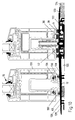
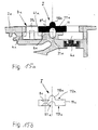
- Fig. 1 the sliding element according to the invention is shown in a view.
- the sliding element 1 is arranged here on the right side of a wall opening 10, on the left next to it a fixed element 15 is arranged.
- a fixed element 15 Schematically indicated, the door fittings 22, 22 'can be seen.
- the door fittings 22, 22 ' are moved by the opening handle 14 so that they are moved similarly up or down.
- the wall opening 10 is provided in the wall 16.
- the sliding element 1, as well as the fixed element 15 are based on the support 12 and the bottom 12 from. As already stated, the terms support and ground are synonymous to understand.
- Fig. 2 it is indicated that the sliding element 1 by the sliding movement 11 to the left is movable so as to open the wall opening 10 at least partially.
- the sliding element 1 By a movement of the sliding element 1 to the right, the wall opening 10 is completely closed, in cooperation with the fixed element 15.
- the sliding element 1 it is possible to dispense with the arrangement of a fixed element 15. In this embodiment, then, the sliding element 1 would close or release the entire wall opening 10.
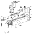
- the sealing element 3 is inserted in a provided on the bottom or in the support 12 groove-like 40 receiving profile 4.
- the sealing element 3 cooperates with a magnetic counterpart 30, which is arranged, for example, on the lower edge 19 of the sliding element.
- the magnetic counterpart part 30 is arranged on a support bar 21 arranged on the underside of the sliding element 1.
- Magnetalleteil 30 and sealing element 3 in opposition such that the magnetic forces act in an ideal manner, wherein the magnetic forces are greater than the gravity of the sealing element 3 and thus cause an attraction, which lead to a sealing of the gap 18.
- the groove 40 of the receiving profile 4 has no over the entire groove height vertically extending groove walls. At its upper end inwardly standing stop strips 41, 42 are provided. These act together with outboard stop leg 32 of the otherwise U-shaped sealing element 3.
- the U-shaped sealing element 3 is inserted in the groove 40 so that the opening of the U is down.
- the arrangement is chosen so that, for example, the left stop bar 41 is integrally connected to the receiving profile 4. But it is also possible to provide a removable stop bar 42, which is provided in the example shown in FIG. 3 at the same time for the left and right sealing element 3.
- the stop bar 42 is fastened by corresponding threaded screws in the receiving profile 4. Conveniently serves in this embodiment, a stop bar 42 for two sealing elements.
- a foam coating 33 is optionally provided either on the leg of the U-shaped sealing element 3 or on the magnetic counterpart 30. At the same time, this foam coating 33 also effects the formation of a small spacer that does not hinder the tightness, which facilitates the separation of the sealing element 3 from the magnetic counterpart part 30 in the case of the opening of the sliding element 1. In this respect, the foam coating 33 is part of the sealing element 3 or of the magnetic opposite part 31.
- a separating device 2 which serves to separate the sealing element 3 from the magnetic counterpart part 30.
- the separating device 2 is formed in the embodiment shown here by a support beam 21, which is arranged at the lower edge 19 of the sliding element 1 in a recess 13. This support beam 21 carries in the embodiment shown here, the magnetic counter parts 30th
- the support bar 21 is connected to the door fitting 22.
- the door fitting 22 is, for example, a commercially available door hinge which, for example, serves to drive locking bolts and so on. Instead of a door hinge but also appropriate pull or operating rods are used. In general, these force-transmitting elements are described and characterized as door fittings 22 in the context of this invention.
- the door fitting 22 is connected at the lateral ends of the support beam 21 thereto. This is done, for example, by the indicated fastening screw.
- the arrangement is chosen so that the depth of the recess 13 is greater than the thickness of the support beam 21. This means that the support bar 21 in the recess 13 can move upwards, vertically and retreat. Since the magnetic counter parts 30 are located at its lower edge, a mechanism is thus provided which serves to remove or separate the magnetic counterpart part 30 from the sealing element 3.
- the necessary vertical movement 20 is impressed on the support beam 1 by the door fitting 22, 22 '. Reference is made to FIG. 1.
- the opening handle 14 also acts on the door fittings 22, 22 '.
- the opening handle 14 is indicated in two positions. In the first, excellent position, the closed position is executed. In this case, the opening handle 14 is vertical. In the second, dashed lines indicated position of the opening handle 14 is rotated by 90 ° in the horizontal.
- the open position of the opening handle 14 ' communicates with the upper layer of the support beam 21', which is also shown in dashed lines.
- the lower position of the excellent support beam 21 communicates with the perpendicular opening handle 14.
- the training is chosen so that a similar movement of the door fittings 22, 22 'is provided at the various lateral ends of the support beam 21 due to the movement of the opening handle 14.
- a corresponding conversion gear is provided in order to ensure that the right 22 and left 22 'part of the door fittings each move in the same direction, ie evenly up or evenly down.
- the operation of the opening handle 14 for opening the sliding element 1, the separation device 2 for separating the sealing element 3 from the Magnetumbleteil 30 provides.
- the separating device 2 raises the magnetic opposite part 30 indirectly or directly until the adhering to the Magnetalleteil 30 by the magnetic forces sealing element 3 rests against the stop bar 42, 41. Further movement of the Magnetalleers 30 then leads to the formation of an air gap between the Magnetalleteil 30 and the sealing element 3. Since the distance between the two magnetic parts increases and the effectiveness of the magnetic forces with increasing Distance decreases, then drops the heavier sealing element 3 in the groove 40 down and the magnetic element 30 is free of the sealing element. 3
- the support beam 21 still carries on its outer side a pinch seal 31.
- This pinch seal acts as an additional sealing level.
- the receiving profile 4 is part of a dewatering device 5.
- This advantageous embodiment ensures that a reliable, powerful, magnetic-force-based sealing is also available for firedamp impacted sliding elements available.
- the dewatering device ensures that water present on the sliding element is discharged downwards.
- the groove 40 of the receiving profile 4 has drainage channels 50. Water that passes behind the pinch seal 31 will initially enter the groove 40. It is favorable that no complete fit of the sealing element 3 is provided in the groove 40 in order to provide a space for the drainage of water. Water that collects in the groove 40 is then drained through drainage channels 50 located in the bottom, as indicated by the dotted line 56.
- the third sealing plane which is formed by the second sealing element (the right sealing element 3)
- the design of the sealing element 3 is the same as that of the first, left-hand sealing element 3.
- the drainage channels are not in the bottom of the groove 40 but in the groove portion of the groove wall.
- the embodiment according to the invention therefore represents a drainage system formed by three different sealing levels.
- the applicant reserves the right to request independent protection for the special design of this drainage device in connection with the use in sliding elements.
- a hose can serve, which can be plugged onto the nozzle 57. This makes it possible to direct incoming water from the wall opening far away to a drainage or discharge or the like.
- the invention provides that the dewatering device 5 at the top has a on the outside of the wall opening 10 extending tread 51.
- the design of this treadplate increases the stability of the entire arrangement.
- the receiving profile 4 is integrally connected to the tread bar 51 in the right area.
- the receiving profile 4 is made with the tread 51 for example of aluminum in an extrusion process. It is envisaged that the tread bar 51 extends over the entire width of the opening 10 (see FIG. 2) and thus extends below the fixed element 15.
- a fixed element 15 is supported on the tread bar 51 via a compensating lining 52.
- the compensating lining 52 is arranged, for example, on the underside of the fixed element.
- the Austiciansunter spatt für 52 is wider than the width of the fixed element 15. It has on the inside, in the displacement region of the sliding element 1, a guide spring 53 for the open sliding element 1 on. Conveniently, this guide spring 53 cooperates with the corresponding groove, which is provided on the underside 19 of the sliding element 1.
- the support beam 21 carries a downwardly open guide groove 23 in order to cooperate with the guide spring 53.
- the tread bar 51 is arranged on the outside. However, the dewatering device 5 also extends a little way into the interior, so as to form a channel 54, on which one or more support wheels 17 of the sliding element 1 find a guide.
- the dewatering device 5 is formed in two or more parts. Conveniently, at least two parts of the dewatering device 5 are connected to one another by one or more insulating webs 55. These are for example Double T-shaped (below) or E-like (top) arranged in Fig. 3 below the right sealing element 3. Intermediate spaces are filled with appropriate insulation material.
- the insulating bars are characterized by a poor heat conductive material particularly.
- FIG. 4 shows the detail of a further embodiment of a sliding element 1 according to the invention corresponding to FIG. 3.
- the same parts are provided with the same reference numerals as in Fig. 3.
- Parts of the dewatering device 5, which have already been described with the figure description of Fig. 3, have been omitted for the sake of simplicity.
- the embodiment of the sliding element according to FIG. 4 represents the lower part of the sliding element with guide rollers mounted on top.
- the upper end of the sliding element is not shown.
- the sliding element is guided with its upper guide rollers in a rail, for example, a Schwebetenaufhfitung. Between the lower edge of the sliding element and the support remains a gap which is closed by the magnetic seal.
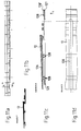
- FIG. 9 shows a further variant of the invention.
- the structure is substantially similar to that of FIG. 3, which is why, to avoid repetition, only the different features are specifically highlighted.
- Essential in this variant, as well as in the other variants of FIG. 5 to 7 is that the support wheel 17 in the profile of the sliding element is centrally installed and not laterally located next to it, as indicated for example in Fig. 3.
- the support wheel 17 rolls off on the stop bar 42, which is arranged between the two sealing elements 3, 3 '.
- the wheel 17 in this case has a circumferential cam 71, which is designed like a ring and engages in a recess 72 of the stop bar 42.
- the stop bar 42 is connected by a fastening screw 80 with the receiving profile 4.
- openings 8 are provided.
- the Magnet literallyteil 30 is seen in section as an inverted T formed.
- the upstanding stem engages a pin-like manner in a groove 100 on the underside of the sliding element 1. Assembly and alignment is greatly facilitated.
- a thin spacer for example made of sponge rubber, plastic or the like.
- this edition also acts as a seal, as it has a certain elasticity.
- This compensating lining 52 is also formed inverted T-like and engages in a groove 101 on the underside of the fixed element 15 a.
- a seal 500 is provided, which in particular ensures that possibly occurring dimensional inaccuracies or shrinkage does not lead to leaks.
- a positioning means is skillfully provided on the compensating lining 52, which cooperates with a positioning means of the tread 51.
- This makes it possible to facilitate the alignment of the Ausretesunter Stahltt für satusky satusky satusky satusky satusky satusky satusky satusky satusky satusky satusky satusky satsky , etc.
- a similar structure as shown in Fig. 9 is shown.
- the sliding element 1 according to the invention is designed here as a wooden component.
- the components are installed in corresponding milled grooves.
- the wheel 17 has a circumferential groove 70 which cooperates with a survey 73 of the stop bar 42.
- the stop bar 42 is in a receptacle 37, which is groove-like incorporated in the receiving profile 4, used.
- the receptacle 4 for example, a positioning spring 36 which cooperates with a positioning groove 35 of the stop bar 42.
- the transverse extent of the receiving profile is considerable, so favorably in the direction from the inside to the outside (transverse to the longitudinal extension of the receiving profile 4) several, for example, two Abatweilfeine 59 use. Since several feet are arranged along the longitudinal extension of the receiving profile, a table-like storage results.
- the sliding element according to the invention is designed as a plastic component. Between the Magnetumbleteil 30, which is inserted into the groove 100 of the sliding element, an adapter profile 34 is provided.
- the fixed element 15 is, as shown for example in Fig. 7, fixed by a fastening screw 58 either from top to bottom or from bottom to top.
- Fig. 7 shows the variant in which the wheel 17 has a circumferential groove 70 and the stop bar 42 has a survey 43 on which the wheel 17 is guided and controlled rolls.
- Fig. 8 an enlarged detail of the stop bar 42 is shown in Fig. 8 in cross section.
- a survey 73 which is suitable to cooperate with a circumferential groove.
- the bar is reversed, so is the recess 72 above, which is used for rollers with circumferential cams.
- the arrangement is chosen so that the mounting opening 8 can be used on the left side for both cases of use, as well as the two positioning grooves 35, 35 '. Therefore, the stop bar is not about its longitudinal axis to rotate, but about its transverse axis.
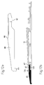
- Fig. 9, 10 a further inventive variant of the embodiment of the sliding element is shown.
- the variant according to FIG. 9, 10 is e.g. used when it can be dispensed with a correspondingly expensive drainage, which is installed in the floor.
- a floor covering 124 rests on the raw floor 125.
- the raw floor 125 has no recesses or heels in the region of the sliding element 1. It is good to see that the entire height of the support 12 is relatively low.
- the edition shown here and also belonging to the invention consists of several interacting elements.
- an embodiment of the support 12 is also described in more detail with reference to the figures 11a to 11d.
- the support 12 has a substantially flat area 126.
- the grooves 40 for receiving the receiving profile 4. In the right area of the support 12 are the grooves 40 for receiving the receiving profile 4. The arrangement is chosen so that two sealing elements are provided.
- the support 12 is followed by a thinner end region 127.
- This end region 127 is thinner relative to the flat, left region and is therefore at a lower height level. This is so realized so that above the end portion 127 a Verbinduzigsang 122 can be connected, which then carries on the other side another part 123 of the edition.
- the connecting power 122 is designed as an insulating piece and thus forms a heat or sound insulation.
- the entire height of the support is matched to the height of the floor covering 124. Therefore, it is possible to form the pad portion 123 on the floor pad 124, thereby concealing small gaps, etc. in the connection of the floor panel.
- the support 12 is in the lying on the outside, flat portion 126 and the inner, in particular the recesses having area on.
- the stop bar 42 which is removable at any time.
- the upper edge of the sealing strip also communicates with the upper edge of the support part 123 or in the flat region 126.
- latching elements 128, 128 ' are provided on the end portion 127 to connect to the connector 122.
- the variant according to the invention shown here sits on a bottom plate 6 arranged underneath.
- the bottom plate extends over almost the same surface area as the Pad 12, only in the right, inner area, the bottom plate 6 is shortened so as not to collide with the floor covering 24.
- the essential advantage of the bottom plate 6 is that a definerter water drainage channel 120 is available and the running water does not stand up on the Rohfuß founded 125. It is possible to choose the arrangement so that there is a defined gradient in the bottom plate 6 in order to reliably dissipate the moisture or water.
- a drainage channel 50 is provided in the support. This drains the penetrating into the receiving groove 40 water forward on the bottom plate. 6
- Transverse to the longitudinal extent of the support transverse channels 120 are provided in the support 2 in order to be able to derive the water forward.
- holding means 121 are provided to connect the support 12 and the bottom plate 6 together.
- these holding means 121 are formed as clip connections or as upwardly projecting, engaging hooks.
- corresponding hooks are integrally formed on the bottom plate 6, which engage with corresponding projections forming recesses 128 of the support 12 and hold latching there.
- a plurality of holding means 121 are arranged one behind the other in transverse extension of the support (from the inside to the outside) of the rest 12 (next to each other in section).
- corresponding holding means 121 provided to produce a reliable connection between the support 12 and the bottom plate 6.
- an end piece 60 connects on the bottom plate 6 on the outside.
- the end piece 60 is provided with a clip connection 62 which cooperates with locking lugs 129 on the support 12 such that a firm connection results.
- the arrangement is chosen so that the tail 60 Wasserableitkanäle 61 which communicate with the transverse channel 120 and direct the water guided thereby further out.
- the thickness of the underside of the end piece 60 corresponds to the thickness of the bottom plate 6.
- Fig. 11d shows a bottom view of the overlay 12, e.g. is shown in section in Fig. 11c.
- the transverse channel 120 extends from the outside to the region of the inner, second sealing element 3 and also drains this channel, if moisture or water should penetrate here.
- the cross channel 120 is e.g. created by a machining.
- pinch seals are described, wherein between the pinch seals 38 one or two sealing elements 3, as described, are arranged.
- the pinch seal 38 is arranged between the sealing elements 3.
- a plurality of sealing planes arranged one behind the other (from outside to inside) and thus a labyrinth effect thus result.
- Fig. 10 In Fig. 10, almost the same situation is shown as in Fig. 9, except that no bottom plate 6 is used here.
- the invention is therefore also directly on a Rohfußêt 125 erectable.
- the support 12 is the same as that used in FIG. 9. The invention is thus very variable.
- the support 12 is supported, for example, via the webs 125 forming the recess 128 on the unfinished floor 125.
- a support piece 63 is provided under the support 12. This can of course also be used in the arrangement with a bottom plate 6 use.
- the fixed sliding element 15 (drawn here on the left), has on an underside an attachment profile 132, through which the fixed element 15 rests on the support 12. Between the attachment profile 132 and the support 12 seals 130 are provided.
- the attachment profile 132 is pushed and clipped on the underside of the fixed element 15 at this.
- the seal 131 seals the gap between the attachment profile 132 and the frame part 133 of the fixed element 15.
- Fig. 12a, 12b the end piece 60 is still shown.
- the arrangement is chosen so that the surface of the flat area 126 opens without significant shoulder, as flush or steadily as possible in the surface 65 of the end piece 60. Therefore, a small shoulder 66 forms on the end piece 60, approximately in the middle, to form the connection area for the support 12. Further outward with respect to this paragraph (on the right) is followed by the clip connection 62, in which case the end piece 60 has a projecting tongue 67 which cooperates with the locking lugs 129 of the support 12.
- the magnetic strip according to the invention la in side view - from the front side - shown.
- the magnetic strip la consists according to this embodiment of a U-shaped profile body 700, the transverse web 700a is oriented upward and the legs 700b extend downwards. Quersteg 700a and leg 700b form a recess 601.
- the recess for saving material is provided.
- the magnetic strip 1a is entirely made of a magnetic material, so that the magnetic strip 1a is attracted to the action of magnetic forces.
- the profile body 700 consists of a sealing material such as rubber, plastic, Teflon or the like, wherein the magnetic element in the form of individual magnets or a magnetic profile can be inserted into the recess.
- the magnetic strip now consists of the non-magnetic profile body and a magnetic element.
- a projection 200 is provided at the lower ends of the legs 700 b, each directed toward the outside.
- This projection is formed by an upwardly directed flat surface 300 and a curve 550 extending from the flat surface to the lower end of the magnetic strip 1a.
- This rounding 550 may also be bounded below by a flat surface 400. Plane surface 300 and rounding 550 form a line 800.
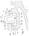
- FIG. 14 the detail of a bottom rail 900 according to the invention is shown with a magnetic strip la.
- These Magnetic strip 1a is currently displayed in a state as it is inserted into the receiving profile 201 of the bottom rail 900.
- the left side of the recess 201 has an undercut 10a.
- the magnetic strip 1a is inserted with its left protrusion 200 under a fixed to the bottom rail stop bar 250 and aligned by a pivoting movement in the direction of arrow A in a vertical direction.
- the right projection 200 slides with its rounding 550 over the upper boundary edge 130 of the receiving profile 201.
- the magnetic strip la is deposited on the bottom of the receiving profile 201, wherein it comes to rest with the front ends 400 of the legs 700b on the bottom of the receiving profile 201.
- a releasable stop bar (not shown) is connected to the bottom rail 900 on the right side of the receiving profile 201, so that the right projection 200 forms an upwardly limiting stop.
- the magnetiaiste 1a is fixed in the receiving profile 201 of the bottom rail 900.
- the movement is bounded above by the stop bars 250 and down through the bottom of the receiving profile 201.
- the line 800 formed by the flat surface 300 and rounding 550 the magnetic strip slides along the side walls of the receiving profile. Due to the small contact surface, the friction of the magnetic strip is reduced to the receiving profile.
- an advantage of the rounding 550 is that even with a non-rectilinear movement, the magnetic strip 1a in the receiving profile 201 does not tilt.
- Fig. 15a shows a section through an arrangement with a roller guide I and the part of a bottom rail 2a.
- the roller guide I is designed as a profile strip 11a.
- the profile strip has an elevation 110a in its center and a groove 111a on the opposite side.
- a recess 21a is provided in the bottom rail 2a, which serves to ensure that in the event that the profile strip by 180 ° should be installed rotated, the increase 110a can be recorded there.
- a magnet 31a is designed as a magnetic strip for this purpose.
- the reference numeral 8a indicates a hole in the profile strip 11a, which is recessed, for example, and which serves to receive a countersunk screw, not shown.
- the countersunk screw is guided for fastening the profile strip through the bore 8a and screwed into a threaded hole 6a in the bottom rail 2a and thereby the profile strip 11a connected to the bottom rail 2a.
- the sealing element is indicated schematically.
- the sealing element 3a is formed from the magnet 31a and the magnetic opposite part 32a, not shown here.
- Fig. 15b shows a section through a profiled strip 11a.
- the arrow indicates that the roller guide is shown in its execution as a profile strip 11a.
- the increase 110a is used to guide not yet shown roles a sliding door or a sliding window.
- Such rollers may be formed either convex or cokaved at its outer radius in cross-section. For this reason, the invention proposes to make the roller guide I such that it makes both variants technically feasible without much effort. If, for example, a roller is concave, the roller guide I is installed in the illustrated form according to FIGS. 15a and 15b. The role is thus performed safely and can not dodge to the left or right.
- the roller guide I denotes the opening, through which the fastening means, for example a countersunk head screw is guided.
- the opening 8a is sunk on both sides, so there a countersunk screw in it can also be easily, without forming a resistance to the rollers, can be sunk.
- Reference numerals 112a and 113a designate guide grooves within which the wheel or the roller can additionally be guided. Cleverly, the distance of the guide grooves is selected so that spaced apart in its center, the openings 8a provided can wertden. If you then screwed the countersunk screws so that their slot is formed corresponding to the guide rollers, a guide is easily guaranteed on both sides.
- Fig. 16 shows an embodiment of a sliding element II with bottom rail 2a and roller guide I according to the invention.
- the sliding element II is designed as a sliding door or sliding window.
- the movable part of the sliding element II acts together with a bottom rail 2a, the sealing element 3a, consisting of magnets 31a and provided with the sliding element II Magnetismus kind 32a, for sealing together.
- the bottom rail 2a is also shown in section, as the sliding element II.
- a recess is milled, in which a support wheel 17a, which is seen for example as a roller with the cross-section convex outer edges.
- To guide the sliding element II serves the roller guide I, which is formed in the illustrated variant as a profile strip 11a.
- Fig. 17 differs from Fig. 16 only in that now the groove 111a facing down and the elevation 110a upwards.
- the support wheel 17a has a concave outer contour. Due to the interaction with the profile bar 11a, which is now arranged the other way round, a sufficiently stable guidance is ensured here as well. All other features have already been presented in the description of FIG. The reference numerals are used in the same way.
- Fig. 18 shows a three-dimensional view of a bottom rail 2a with a roller guide I according to the invention. Due to the three-dimensional representation is very well seen that the roller guide I is designed as a profile strip 11a, which can be produced very well and inexpensively, for example, in the strand, pressing or drawing process.
- the profiled strip 11a according to the invention is also provided as a completion element for the floor rail according to the invention, in particular for floor rails with magnetic seals.
- the roller guide 11a serves at the same time in each case inwardly facing completion of the grooves 4a, whereby the magnets, not shown, are guided safely in this guide.
- the profiled strip 11a is attached to the bottom rail 2a.
- the screws can be unscrewed and the profile strip can be removed. This allows, for example, to achieve a simpler and overall more favorable cleaning when the grooves 4a become dirty.
Abstract
Description
Die Erfindung betrifft ein Schiebeelement, insbesondere eine Schiebetüre oder ein Schiebefenster. Es ist bekannt, Schiebeelemente durch eine im Wesentlichen längsverlaufende Schibebewegung zum Öffnen oder Verschließen zumindest eines Teiles einer Wandöffnung einzusetzen. Eine solche Wandöffnung kann sich dabei sowohl in einer Innen- wie auch einer Außenwand befinden. Schiebetüren der vorgenannten Art werden zum Beispiel gerne im Eingangsbereich von Verkaufsgeachäften eingesetzt. Sie finden aber auf im privaten Bereich Verwendung, zum Beispiel als Verbindungstür vom Wohnzimmer zum Garten.The invention relates to a sliding element, in particular a sliding door or a sliding window. It is known to use sliding elements by a substantially longitudinally extending sheave movement for opening or closing at least a part of a wall opening. Such a wall opening can be located both in an inner wall and an outer wall. Sliding doors of the aforementioned type are used for example in the entrance area of sales forces. she but find use in the private sector, for example, as a connecting door from the living room to the garden.
Soweit im Rahmen dieser Anmeldung von einer Schiebetüre gesprochen wird, ist die Erfindung nicht auf eine Schiebetüre beschränkt zu verstehen, gleichwohl ist damit jede Form eines Schiebeelementes gemeint.As far as is spoken in the context of this application of a sliding door, the invention is not limited to a sliding door to understand, nevertheless, it means any form of a sliding element.
Die genannten Schiebetüranlagen sind verhältnismäßig kompliziert, da sie neben dem schiebbaren Element auch aus einem feststehenden Element bestehen. Das verschiebbare Element muß eine entsprechende Führung besitzen und gleichwohl in der öffnungs- beziehungsweise der Verschiebebewegung stabil geführt, aber leichtgängig beweglich sein. Gerade im Außenbereich wird von einer entsprechenden Schiebetüranlage auch absolute Dichtheit gegen Wind oder Regen zwingend erwartet. Dies führt dazu, daß bekannte Schiebelemente im Außenbereich am Boden einen erheblichen Aufbau aufweisen, um durch eine möglichst hohe Schwelle oder Falz die geforderte Dichtheit zu erreichen. Die Ausgestaltung des Schiebeelementes gerade im Bodenbereich ist daher im Stand der Technik durch hohe Profile gekennzeichnet, welche als Stolperfalle zu betrachten sind. Zwar gewährt eine entsprechend "hohe Schwelle" eine ausreichende Sicherheit vor eindringendem Regenwasser und dergleichen, jedoch ist das Durchschreiten der Öffnung durch die erheblichen Barriere gefährlich oder sehr erschwert und für Rollstuhlfahrer letztendlich unmöglich.The said sliding door systems are relatively complicated, since they consist of a fixed element in addition to the sliding element. The displaceable element must have a corresponding guide and yet stably guided in the opening or the sliding movement, but be easily movable. Especially in the outdoor area is expected by a corresponding sliding door system and absolute tightness against wind or rain. This has the effect that known sliding elements in the outdoor area at the bottom have a considerable structure in order to achieve the required tightness through the highest possible threshold or fold. The design of the sliding element just in the bottom area is therefore characterized in the art by high profiles, which are to be regarded as a trip hazard. Although a corresponding "high threshold" provides adequate security against the ingress of rainwater and the like, however, the passage through the opening is dangerous or very difficult due to the considerable barrier and ultimately impossible for wheelchair users.
Die Erfindung hat es sich daher zur Aufgabe gemacht, ein möglichst barrierefreies Schiebeelement zu realisieren.The invention has therefore taken on the task of realizing a barrier-free as possible sliding element.
Zur Lösung dieser Aufgabe geht die Erfindung aus von einem Schiebeelement wie eingangs beschrieben und schlägt vor, daß in der geschlossenen Stellung des Schiebeelementes ein Spalt zwischen dem unteren Rand des Schiebeelementes und der Auflage durch mindestens ein durch magnetische Kräfte bewegbares Dichtelement verschießbar ist.To achieve this object, the invention is based on a sliding element as described above and proposes that in the closed position of the sliding element, a gap between the lower edge of the sliding element and the support can be fired by at least one by magnetic forces movable sealing element.
Die Anordnung des durch magnetische Kräfte bewegbaren Dichtelementes erlaubt es, im geschlossenen Zustand des Schiebeelementes ein absolut wind- und wasserdichtes Schiebeelement zur Verfügung zu stellen. Gleichzeitig wird durch den erfindungsgemäßen Vorschlag realisiert, daß im geöffneten Zustand ein barrierefreies Schiebeelement, insbesondere eine barrierefreie Schiebetüre oder ein barrierefreies Schiebefenster zur Verfügung steht. Dabei ist die Erfindung so ausgestaltet, daß vor oder mit dem Beginn der Verschiebebewegung zum Öffnen des Schiebeelementes das Dichtelement den Spalt, der sonst verschlossen ist, freigibt und so eine freie Verschiebbarkeit erlaubt. Zum Beispiel ist vorgesehen, durch eine Abstreifbewegung, die zum Beispiel von der Verschiebebewegung des Schiebeelementes abgeleitet ist, das Dichtelement so zurückzubewegen, daß der Spalt am unteren Rand frei wird. So stört das Dichtelement auch nicht, wenn das Schiebeelement geöffnet wird.The arrangement of the movable by magnetic forces sealing element allows to provide an absolutely wind and waterproof sliding element in the closed state of the sliding element. At the same time is realized by the proposal according to the invention, that in the open state, a barrier-free sliding element, in particular a barrier-free sliding door or a barrier-free sliding window is available. The invention is designed so that before or with the beginning of the sliding movement to open the sliding element, the sealing element releases the gap, which is otherwise closed, and thus allows a free displacement. For example, it is provided by a stripping movement, which is derived for example from the sliding movement of the sliding element, the sealing element to move back so that the gap at the bottom is free. So does not bother the sealing element when the sliding element is opened.
In der Regel stützt sich das Schiebeelement über entsprechende Abstützräder, die auch die Längsbeweglichkeit ergeben, auf dem Boden ab. Daher dient der Boden auch als Auflage im Sinne der Erfindung, wenngleich die Erfindung nicht darauf beschränkt ist, daß das Schiebeelement in jedem Fall mit einem unten angeordneten Abstützrad ausgebildet sein muß. Die Erfindung ist in gleicher Weise auch realiserbar bei Schiebeelementen, die zum Beispiel hängend geführt sind und sich dann ebenfalls ein Spalt zwischen dem unteren Rand des Schiebeelementes und der Auflage, hier dem Boden, bildet. Ebenfalls schließt die Erfindung ein, Führungsräder am oberen sowie Abstützräder am unteren Rand des Schiebeelementes vorzusehen, so daß das Schiebeelement leichtgängig ist beziehungsweise sich ohne hohen Kraftaufwand verschieben läßt. Dabei umfaßt die Erfindung sowohl Lösungen bei welchen nur obere oder nur untere Abstützräder, wie auch eine Kombination von oberen und unteren Abstützrädern vorgesehen sind.As a rule, the sliding element is supported on the ground via corresponding support wheels, which also provide longitudinal mobility. Therefore, the floor also serves as a support within the meaning of the invention, although the invention is not limited to the fact that the sliding element must be formed in each case with a support wheel arranged below. The invention is also feasible in the same way with sliding elements, which are guided, for example, hanging and then also forms a gap between the lower edge of the sliding element and the support, here the floor. Also includes the invention, to provide guide wheels on the upper and Abstützräder at the bottom of the sliding element, so that the sliding element is smooth or can be moved without much effort. The invention includes both solutions in which only upper or lower support wheels, as well a combination of upper and lower Abstützrädern are provided.
Das erfindungagemäße Schiebeelement dient dabei dazu, zumindest einen Teil einer Wandöffnung zu verschließen beziehungsweise zu öffnen. Oftmals wird das Schiebeelement mit einem feststehenden Element in der Wandöffnung kombiniert, wobei dann das Schiebeelement aufgrund seiner Ausgestaltung nur einen Teil der WandÖffnung verschließen oder freigeben kann. Bei anderen Anordnungen ist es aber möglich, daß das Schiebeelement die gesamte Wandöffnung verschließt, zum Beispiel das Schiebeelement in die seitlich anschließende Wand einfahrbar ist oder hinter dieser komplett zur Seite fahrbar ist. In beiden Anwendungsfällen ist das erfindungsgemäße Schiebeelement einsetzbar.The inventive sliding element serves to close or open at least part of a wall opening. Often, the sliding element is combined with a fixed element in the wall opening, in which case the sliding element can close or release only a part of the wall opening due to its design. In other arrangements, it is possible that the sliding element closes the entire wall opening, for example, the sliding element in the laterally adjoining wall is retractable or behind this completely mobile to the side. In both cases, the sliding element according to the invention can be used.
In einer bevorzugten Variante der Erfindung ist vorgesehen, daß das Dichtelement mit mindestens einem Magneten ausgestattet ist und das Dichtelement mit einem Magnetgegenteil zusammenwirkt. Als Magneten im Sinne der Erfindung gelten dabei auch magnetisierbare Stoffe wie Ferromagneten, magnetische Keramiken und dergleichen. Es geht darum, die magnetischen Anziehungskräfte auszunutzen, weswegen ein Magnet eingesetzt wird. Günstigerweise werden dabei zwei in Opposition zueinander zu bringende Elemente eingesetzt, um die anziehende Bewegung des Dichtelementes auszunutzen. Dabei wirkt günstigerweise das mit einem Magneten auegestattete Dichtelement oder das magnetisierbare Dichtelement mit einem entsprechenden Magnetgegenteil zusammen. Dabei kann auch das Magnetgegenteil entweder als eigenständiges Bauteil ausgebildet sein oder aber als entsprechend magnetisierter Bereich an dem Schiebeelement oder der Auflage, je nach Ausführungsbeispiel, ausgebildet sein.In a preferred variant of the invention it is provided that the sealing element is equipped with at least one magnet and the sealing element cooperates with a magnetic opposing part. Magnets in the context of the invention also include magnetizable substances such as ferromagnets, magnetic ceramics and the like. It's about exploiting the magnetic attractions, which is why a magnet is used. Conveniently, two elements to be brought into opposition to each other are used to take advantage of the attractive movement of the sealing element. In this case, the sealing element fitted with a magnet or the magnetizable sealing element interacts favorably with a corresponding magnetic opposing element. In this case, the Magnetgegenteil either be designed as an independent component or as a corresponding magnetized area on the sliding element or the support, depending on the embodiment, be formed.
In einer bevorzugten Variante der Erfindung ist vorgesehen, daß eine im wesentlichen vertikale Bewegung des Dichtelementes besteht. Durch eine solche Bewegung wird der sich unter dem Schiebelement befindende Spalt optimal verdeckt. Durch die vertikale Bewegung wird das Dichtelement z.B. nach oben oder nach unten bewegt. Dabei wird die vertikale Bewegung des Dichtelementes nicht in jedem Fall von den magnetischen Kräften geleistet. Im Sinne der Erfindung ist es natürlich möglich, daß die magnetischen Kräfte, z.B. beim Öffnen oder beim Schließen des Spaltes eingesetzt werden und im übrigen die Bewegung durch die Schwerkraft erfolgt. Es ist daher möglich, das bewegliche Dichtelement am Spalt unten (im Boden) oder oben (auf der Unterseite des Schiebeelementes) anzuordnen.In a preferred variant of the invention it is provided that there is a substantially vertical movement of the sealing element. By such a movement will be under the Sliding element located optimally hidden. By the vertical movement, the sealing element is moved, for example, up or down. The vertical movement of the sealing element is not performed in each case by the magnetic forces. For the purposes of the invention, it is of course possible that the magnetic forces, for example, be used when opening or closing the gap and, moreover, the movement is effected by gravity. It is therefore possible to arrange the movable sealing element at the gap below (in the ground) or above (on the underside of the sliding element).
In einer weiteren bevorzugten Ausgestaltung der Erfindung wird vorgeschlagen, daß sowohl in der geöffneten als auch in der geschlossenen Stellung des Schiebeelementes das Dichtelement parallel zum Schiebeelement ist. Die Erfindung ist insbesondere bei längsverschieblichen Schiebeelementen, sogenannten Schiebefenstern oder Schiebetüren einsetzbar. Bei diesen werden die Schiebeelemente in einer geraden Führung längs verschoben und geben somit die Öffnung frei oder verschließen diese.In a further preferred embodiment of the invention, it is proposed that both in the open and in the closed position of the sliding element, the sealing element is parallel to the sliding element. The invention can be used in particular with longitudinally displaceable sliding elements, so-called sliding windows or sliding doors. In these, the sliding elements are moved longitudinally in a straight guide and thus release the opening or close it.
Natürlich ist die Erfindung auch alternativ bei solchen Anwendungsbereichen einsetzbar, wo z.B. Faltelemente als Schiebeelemente vorgesehen sind. Hierbei ist zu beachten, daß auch bei solchen Elementen im Schwellenbereich ein Spalt zu verschließen ist, was durch die Erfindung in zuverlässiger Weise erfolgen kann. Die Erfindung ist dabei sowohl bei Faltschiebeelementen, wie auch bei längsbeweglichen Schiebeelementen einsetzbar.Of course, the invention may alternatively be used in such applications where e.g. Folding elements are provided as sliding elements. It should be noted that even with such elements in the threshold range, a gap is closed, which can be done by the invention in a reliable manner. The invention can be used both in Faltschiebeelementen, as well as longitudinally movable sliding elements.
In einer vorteilhaften Ausgestaltung der Erfindung ist eine Trennvorrichtung vorgesehen, die das Trennen des Dichtelementes vom Magnetgegenteil, insbesondere vor oder zu Beginn der Öffnungsverschiebebewegung des Schiebeelementes bewirkt. Durch das Anordnen der Trennvorrichtung wird das Öffnen des Schiebeelementes erleichtert, da beim Schieben neben der Überwindung der Reibungskräfte auch die Adhäsionskräfte des miteinander zusammenwirkenden Dichtelementes und des Magnetgegenteiles überwunden werden muß. Um gerade bei großen Schiebeelementen die aufzuwendende Kraft nicht zu groß werden zu lassen ist es günstig, eine entsprechende Trennvorrichtung vorzusehen.In an advantageous embodiment of the invention, a separating device is provided which causes the separation of the sealing element from the magnetic opposite, in particular before or at the beginning of the opening displacement movement of the sliding element. By arranging the separating device, the opening of the sliding element is facilitated, since when pushing in addition to overcoming the frictional forces and the adhesion forces of each other cooperating sealing element and the magnetic counterpart must be overcome. In order not to let the force to be expended, especially with large sliding elements, it is favorable to provide a corresponding separating device.
Gemäß der Erfindung kann die Trennvorrichtung verschiedenste Ausgestaltungen aufweisen. Zum einen ist es möglich, die Trennvorrichtung sehr einfach mit dem Dichtelement zusammenwirkend auszubilden.According to the invention, the separating device can have a very wide variety of configurations. On the one hand, it is possible to form the separating device cooperatively with the sealing element very easily.
Zum Beispiel befindet sich an dem Dichtelement eine seitliche, mit der Horizontale einen spitzen Winkel einschließende Führung, die derart ausgebildet ist, daß das Schiebeelement, welches sich öffnet, das Dichtelement zunächst mitnimmt, aber dann aufgrund dieser schrägen Dichtelementführung das Dichtelement automatisch nach unten gezogen wird und sich so das Dichtelement von dem Magnetgegenteil entfernt. In dieser Variante wäre diese schräge Führung die Trennvorrichtung.For example, located on the sealing element is a lateral, with the horizontal an acute angle enclosing guide, which is designed such that the sliding element which opens, the sealing element initially entrains, but then due to this oblique sealing element guide the sealing element is automatically pulled down and thus the sealing element is removed from the magnetic opposing part. In this variant, this oblique guide would be the separator.
Die Trennvorrichtung kann zum Beispiel aber auch durch einen Trennkeil gebildet sein, der bewirkt, daß das Dichtelement von dem Magnetgegenteil getrennt wird, wenn das Schiebeelement bewegt wird. Hierbei ist es insbesondere von Vorteil, wenn das Trennen des Dichtelementes vom Magnetgegenteil vor der oder zu Beginn der Öffnungsverschiebebewegung durchgeführt wird, um die aufzuwendenden Kräfte verhältnismäßig gering zu halten.However, for example, the separator may also be formed by a separating wedge which causes the sealing member to be separated from the magnetic counterpart when the sliding member is moved. It is particularly advantageous if the separation of the sealing element is performed by the magnetic opposite part before or at the beginning of the opening sliding movement to keep the forces to be used relatively low.
In einer bevorzugten Variante der Erfindung ist vorgesehen, daß die Trennvorrichtung eine im Wesentlichen vertikale Bewegung des Dichtelementes oder des Magnetgegenteiles bewirkt. Die Erfindung ist nicht darauf festgelegt, daß die Trennvorrichtung nur mit dem Dichtelement oder nur mit dem Magnetgegenteil zusammenwirkt. Vielmehr erreichen beide Variante das erfindungsgemäße Ziel.In a preferred variant of the invention it is provided that the separating device causes a substantially vertical movement of the sealing element or the magnetic opposing part. The invention is not specified that the separator cooperates only with the sealing element or only with the magnetic opposite. Rather, both variants achieve the goal of the invention.
Auch legt sich die Erfindung nicht darauf fest, daß die Trennvorrichtung, wie in einer bevorzugten Variante vorgeschlagen, an dem Schiebeelement, sich mit diesem mitbewegend, ausgebildet ist. Es ist alternativ in gleicher Weise möglich, die Trennvorrichtung an der das Schiebeelement führenden Führung oder der Auflage, also dem Boden, anzuordnen.Also, the invention does not specify that the separation device, as proposed in a preferred variant, on the sliding element, with this mitbewegend, is formed. It is alternatively possible in the same way, to arrange the separating device on the guide element guiding the sliding element or the support, that is to say the base.
Auch die Ausgestaltung des Magnetgegenteils ist erfindungagmäß sehr variabel ausgebildet. Zunächst ist es möglich, das Magnetgegenteil feststehend auszubilden. Zum Beispiel ist das Magnetgegenteil zwar an dem Schiebeelement mit diesem mitfahrend ausgebildet, aber relativ zum Schiebeelement feststehend. Natürlich ist es möglich, das Magnetgegenteil auch an der Auflage absolut feststehend auszubilden. Alternativ hierzu ist es möglich, daß das Magnetgegenteil ebenfalls wie das Dichtelement beweglich ausgebildet ist und die beiden Elemente, also Dichtelement und Magnetgegenteil zusammenwirkend den am unteren Rand des Schiebeelementes ansonsten bestehenden Spalt abdichten.The design of the magnetic opposing element is also very variably designed according to the invention. At first, it is possible to form the magnetic member fixedly. For example, the magnetic other part is indeed on the sliding element with this moving, but fixed relative to the sliding element. Of course it is possible to form the Magnetgegenteil also absolutely fixed on the support. Alternatively, it is possible that the Magnetgegenteil is also designed as the sealing element movable and the two elements, so sealing element and Magnetgegenteil cooperatively seal the gap at the bottom of the sliding element otherwise existing.
In einer bevorzugten Ausgestaltung der Erfindung ist vorgesehen, daß das Magnetgegenteil und/oder das Dichtelement leistenartig ausgebildet ist beziehungsweise sind. Es ist unter Umständen ausreichend, daß das Magnetgegenteil nur Abschnittsweise eingesetzt wird, das Dichtelement hat aber den gesamten Spalt zu verdecken, weswegen es günstig ist, daß sich zumindest dieses leistenartig über die gesamte Wandöffnung, die durch das Schiebeelement verschlossen wird, erstreckt. Für einen sicheren Verschluß des Luftspaltes ist es dabei günstig, daß sich auch das mit dem Dichtelement zusammenwirkende Magnetgegenteil ebenfalls leistenartig über die gesamte Öffnungslänge erstreckt.In a preferred embodiment of the invention it is provided that the magnetic opposite part and / or the sealing element is designed like a strip or are. It may be sufficient under certain circumstances that the magnetic other part is used only in sections, but the sealing element has to cover the entire gap, so it is favorable that at least this strip-like over the entire wall opening, which is closed by the sliding element extends. For a secure closure of the air gap, it is advantageous that also cooperating with the sealing element Magnetgegenteil also extends like a strip over the entire opening length.
In einer bevorzugten Variante der Erfindung wird vorgeschlagen, daß das Schiebeelement zwei parallel angeordnete Dichtelemente aufweist. Der Abdichtungseffekt durch zwei in Richtung von außen nach innen hintereinander angeordneten, bevorzugterweise parallel verlaufenden Dichtelementen ist günstig, da dadurch eine Art Labyrinthdichtung erzielt werden kann und so das erfindungsgemäße Schiebeelement in noch effektiverer Weise abdichtbar ist, insbesondere abdichtbar ist für Schlagregen und dergleichen.In a preferred variant of the invention, it is proposed that the sliding element has two sealing elements arranged in parallel. The sealing effect by two arranged in the direction from outside to inside one behind the other, preferably parallel sealing elements is low, as this way a kind of labyrinth seal can be achieved and so the sliding element according to the invention can be sealed in an even more effective manner, in particular can be sealed for driving rain and the like.
In einer bevorzugten Variante der Erfindung ist vorgesehen, daß das Magnetgegenteil an dem Schiebeelement angeordnet ist und das Dichtelement am Boden beziehungsweise in der Auflage. Es ist selbstverständlich aber auch möglich, daß das Magnetgegenteil an der Auflage angeordnet ist und das Dichtelement mit dem Schiebeelement mitfahrend ist. Im Wesentlich ist hier, daß in der Verschließstellung das Magnetgegenteil und das Dichtelement in geeigneter Weise in Opposition zueinander gelangen, derart, daß die magnetischen Kräfte ein Anziehen von Magnetgegenteil und Dichtelement bewirkt.In a preferred variant of the invention it is provided that the Magnetgegenteil is arranged on the sliding element and the sealing element on the ground or in the support. It is of course also possible that the Magnetgegenteil is arranged on the support and the sealing element is moving with the sliding element. Essentially, here is that in the Verschließstellung the magnetic other part and the sealing element in a suitable manner in opposition to each other, such that the magnetic forces causes a tightening of Magnetgegenteil and sealing element.
In einer vorteilhaften Ausgestaltung ist dabei vorgesehen, daß das Magnetgegenteil im Schnitt gesehen T-förmig ausgebildet ist und der nach oben stehende, zapfenartige Stiel des T's in eine Nut an dem Schiebeelement einsteht. Das Schiebeelement ist oftmals als Tür oder Fenster ausgebildet und aus entsprechenden Profilrahmen gebildet. Diese weisen auf ihrer Außenseite eine Nut auf, die dazu geschaffen ist, für Befestigungszwecke eingesetzt zu werden. Wird nun an dem Magnetgegenteil, wie beschrieben, eine T-Form gewählt, so kann der zapfenartige Stiel in die Nut einstehen. Dadurch wird die Montage erheblich erleichtert, da in einfacher Weise eine Fixierung aber auch gleichzeitige Ausrichtung des Magnetgegenteiles erfolgt.In an advantageous embodiment, it is provided that the Magnetgegenteil seen in section is T-shaped and the upstanding, pin-like stem of the T stands in a groove on the sliding element. The sliding element is often formed as a door or window and formed from corresponding profile frame. These have on its outer side a groove which is adapted to be used for fastening purposes. If, as described, a T-shape is selected on the magnetic counterpart, the peg-like stem can protrude into the groove. As a result, the assembly is greatly facilitated, since in a simple manner a fixation but also simultaneous alignment of Magnetgegenteiles done.
Darüberhinaus wird erfindungsgemäß vorgeschlagen, daß ein Adapterprofil für die Befestigung des Magnetgegenteils an dem Schiebelement vorgesehen ist, wobei das Magnetgegenteil mit Hilfe des Adapterprofiles insbesondere in einer Nut des Schiebeelementes zu befestigen ist. Es ergibt sich, daß die verschiedenen Kunststoffprofile, die zur Schaffung eines erfindungsgemäßen Schiebeelementes am Markt erhältlich sind, bezüglich der auf der Unterseite vorgesehenen Nuten nicht gleichartig ausgebildet sind. Um aber mit einem Magnetgegenteil möglichst alle verschiedenen Profile zur Bildung eines erfindungsgemäßen Schiebeelementes ausstatten zu können und gleichzeitig aber nicht verschiedene Magnetgegenteile bevorraten zu müssen, ist es günstig, ein möglichst variabel einsetzbares Adapterprofil zu schaffen und einzusetzen, durch welches ein Magnetgegenteil in eine vielzahl unterschiedlicher Profile, jeweils mit unterschiedlichen Nuten, einbaubar ist.Moreover, the invention proposes that an adapter profile is provided for the attachment of the Magnetgegenteils on the sliding element, wherein the Magnetgegenteil is to be fastened by means of the adapter profile in particular in a groove of the sliding element. It turns out that the various plastic profiles that are available to create a sliding element according to the invention on the market, with respect to the provided on the bottom grooves are not similar. But to equip as possible with a Magnetgegenteil all different profiles to form a sliding element according to the invention and at the same time but not have to stockpile different magnetic counterparts, it is advantageous to create a variably deployable adapter profile and use, by which a Magnetgegenteil in a variety of different profiles , each with different grooves, can be installed.
Günstigerweise ist vorgesehen, daß das Dichtelement in einem in der Auflage angeordneten, nutartigen Aufnahmeprofil eingelegt ist. Die Tiefe der Nut, in welche das Dichtelement eingelegt ist, ist dabei höher als der Spalt zwischen der Auflage und dem darüber liegenden Unterrand des Schiebeelementes, wodurch sichergestellt wird, daß das hochgezogene Dichtelement zuverlässig den Spalt schließt. Die Anordnung des Dichtelementes in einem nutartigen Aufnahmeprofil ergibt auch einen sicheren Schutz des bevorzugt aus entsprechendem Dichtmaterial geschaffenen Dichtelementes, wodurch dieses vor entsprechenden Beschädigungen geschützt ist. Gleichzeitig kann das Dichtelement in einfacher Weise aus dem Aufnahmeprofil herausgenommen werden, um zum Beispiel das Dichtelement und/oder die Nut zu reinigen. Des Weiteren ist es günstig, ein entsprechende Aufnahmeprofil vorzusehen, welches das Dichtelement aufnimmt, da dieses Aufnahmeprofil dann bei der Erstellung des Bauwerkes die Aufgabe einer Schwelle übernimmt, also eine Begrenzung der jeweiligen Fußbodenbeläge im Wandöffnungsbereich ergibt. Dies ist sowieso recht günstig, da im Fußbodenbereich durch das Anordnen eines Estrichs und einer entsprechenden Trittschalldämmung gerade im Anschlußbereich eine Trennung der Fußbodenbeläge erwünscht ist. Hierbei wird Wert darauf gelegt, daß diese Funktion des Aufnahmeprofils zwar die einer Schwelle ist, aber das Aufnahmeprofil in keinster Weise als Schwelle, also als eine nach oben vorstehende, als Stolperschwelle wirkende Anordnung zu verstehen ist.Conveniently, it is provided that the sealing element is placed in a arranged in the support, groove-like receiving profile. The depth of the groove, in which the sealing element is inserted, is higher than the gap between the support and the overlying lower edge of the sliding element, thereby ensuring that the raised sealing element reliably closes the gap. The arrangement of the sealing element in a groove-like receiving profile also results in a reliable protection of the preferably created from corresponding sealing material sealing element, whereby it is protected from corresponding damage. At the same time, the sealing element can be removed in a simple manner from the receiving profile, for example, to clean the sealing element and / or the groove. Furthermore, it is advantageous to provide a corresponding receiving profile, which receives the sealing element, since this receiving profile then takes over the task of a threshold in the creation of the building, so results in a limitation of the respective floor coverings in the wall opening area. This is anyway quite cheap, since in the floor area by placing a screed and a corresponding impact sound insulation just in the connection area a separation of the floor coverings is desired. It is important that this function of the recording profile is that of a threshold, but the recording profile in any way as a threshold, so as an upwardly projecting, acting as a stumbling threshold arrangement to understand.
In einer bevorzugten Ausgestaltung der Erfindung ist vorgesehen, daß das Aufnahmeprofil mindestens eine Anschlagleiste zur Begrenzung der Bewegung des Dichtelementes aufweist. Da das Dichtelement in Längsrichtung, parallel zur verschiebebewegung angeordnet ist, wird durch die Anordnung zumindest einer Anschlagleiste erreicht, daß das Dichtelement nicht ungewollterweise aus dem Aufnahmeprofil herausgleitet oder herausgezogen wird. Durch die Anordnung der Anschlagleiste wird daher sichergestellt, daß das Dichtelement einen definierten Bewegungsbereich erhält und nicht zum Beispiel aufgrund der magnetischen Anziehungskräfte an dem sich öffnenden Schiebeelement anhaftet und dann entsprechend blockiert oder sperrt.In a preferred embodiment of the invention it is provided that the receiving profile has at least one stop bar for limiting the movement of the sealing element. Since the sealing element is arranged in the longitudinal direction, parallel to the sliding movement, is achieved by the arrangement of at least one stop bar that the sealing element is not unintentionally slips out of the receiving profile or pulled out. The arrangement of the stop bar is therefore ensured that the sealing element receives a defined range of motion and not, for example due to the magnetic attraction forces adhering to the opening sliding element and then blocks or blocks accordingly.
In einer erfindungsgemäßen Variante ist dabei vorgesehen, daß die Anschlagleiste demontierbar oder einstückig an dem Aufnahmeprofil angeordnet ist. Selbstverständlich ist es möglich, daß sowohl eine einstückige wie auch eine demontierbare Anschlagleiste an dem Aufnahmeprofil vorgesehen ist. Zum Beispiel begrenzen eine demontierbare Anschlagleiste die Nut auf der einen und die einstückig angeordnete Anschlagleiste die Nut auf der anderen Seite. An der Anschlagleiste liegen dann entsprechende Teile des Dichtelementes an und sind in ihrem Bewegungsbereich begrenzt. Auch wird durch die demontierbare Anschlagleiste die Montage beziehungsweise der Austausch des Dichtelementes erleichtert, da bei Vorhandensein der Anschlagleiste das Dichtelement nicht mit einer entsprechend hohen, genauen Passung an die Nut anzupassen ist.In a variant according to the invention it is provided that the stop bar is arranged dismountable or in one piece on the receiving profile. Of course, it is possible that both a one-piece and a removable stop bar is provided on the receiving profile. For example, a removable stop bar limit the groove on one side and the integrally arranged stop bar the groove on the other side. At the stop bar then apply corresponding parts of the sealing element and are limited in their range of motion. Also, the mounting or replacement of the sealing element is facilitated by the removable stop bar, since in the presence of the stop bar, the sealing element is not adapted to a correspondingly high, accurate fit to the groove.
In einer bevorzugten Variante der Erfindung ist vorgesehen, daß das Aufnahmeprofil Teil einer in die Aufnahme eingebauten Entwässerungsvorrichtung ist. In der Auflage beziehungsweise in dem Boden, was hierzu synonym ist, ist gerade bei Schiebeelementen die die Verbindung zum Außenbereich herstellen, eine Entwässerungsvorrichtung vorteilhafterweise vorgesehen. In der Regel wird die Entwässerungsvorrichtung zusammen mit dem Aufnahmeprofil auf den Rohfußboden aufgebaut. Die Entwässerungsvorrichtung sorgt dafür, daß an dem Schiebeelement ablaufendes Wasser auf der Außenseite verbleibt und entsprechend abgeleitet wird. Durch die Integration des Aufnahmeprofiles in die Entwässerungsvorrichtung werden dabei mehrere Vorteile gleichzeitig realisiert zum einen wird ein integrales Bauteil zur Verfügung gestellt, das entsprechend mehrere Funktionen leistet. Neben der Funktion des Entwässerns, gerade im sensibleren Öffnungsbereich, leistet diese Lösung auch eine wirksame Trennung der Bodenbeläge im Öffnungsbereich und damit einhergehend auch einen Beitrag zur Trittschalldämmung. Darüberhinaus dient diese Anordnung dazu, das Dichtelement aufzunehmen und zu führen.In a preferred variant of the invention it is provided that the receiving profile is part of a built-in recording dewatering device. In the edition or in The floor, which is synonymous to this, is advantageously provided for sliding elements which connect to the outside area, a drainage device. In general, the dewatering device is built together with the receiving profile on the unfinished floor. The dewatering device ensures that running on the sliding element water remaining on the outside and is discharged accordingly. As a result of the integration of the receiving profile into the dewatering device, several advantages are realized simultaneously on the one hand, an integral component is made available which accordingly performs a plurality of functions. In addition to the function of dewatering, especially in the more sensitive opening area, this solution also makes an effective separation of the floor coverings in the opening area and, consequently, also contributes to impact sound insulation. Moreover, this arrangement serves to receive and guide the sealing element.
In einer weiteren Variante der Erfindung ist vorgesehen, daß das Aufnahmeprofil eine nutartige Aufnahme für die Anschlagleiste aufweist. Insbesondere wenn vorgesehen ist, daß die Anschlagleiste demontierbar oder auswechselbar ist, zum Beispiel um die Gestaltung des Schiebelementes beziehungsweise seiner Beschläge zu ändern, kann eine solche Variante von vorteil sein. In die nutartige Aufnahme wird dann gegebenenfalls eine andere Anschlagleiste eingelegt.In a further variant of the invention it is provided that the receiving profile has a groove-like receptacle for the stop bar. In particular, if it is provided that the stop bar is removable or replaceable, for example, to change the design of the sliding element or its fittings, such a variant may be advantageous. In the groove-like recording then optionally another stop bar is inserted.
Die Anordnung einer Aufnahme, welche die Anschlagleiste aufnimmt, hat aber auch den Vorteil, daß die Aufnahme, die ja nutartig ist, mit den Entwässerungskanälen in Verbindung gebracht wird, um in den Bereich der Anschlagleiste eindringende Feuchtigkeit oder Wasser abzuleiten. Überraschenderweise wird daher die Funktion der Anschlagleiste erweitert, da auch diese beziehungsweise deren Aufnahme als Entwässerung dient, wenn diese, wie vorgeschlagen, mit den Entwässerungskanälen in Verbindung steht. Insofern ist der Begriff Entwässerungskanäle abstrakt zu verstehen, und nicht spitzfindig dahin, daß eine Mehrzahl von Kanälen vorgesehen sein müssen. Es geht darum das Wasser über eine gewisse Kanallänge, eben mehreren, zum Beispiel hintereinander angeordneten Kanälen, abzuleiten.The arrangement of a receptacle which receives the stop bar, but also has the advantage that the recording, which is indeed groove-like, is brought into connection with the drainage channels in order to derive moisture or water penetrating into the region of the stop bar. Surprisingly, therefore, the function of the stop bar is extended, as well as this or their inclusion serves as drainage, if this, as proposed, with the drainage channels in conjunction stands. In this respect, the term drainage channels is to be understood abstractly and not subtly meaning that a plurality of channels must be provided. It is about the water over a certain channel length, just several, for example, consecutively arranged channels, deduce.
Geschickterweise ist an der Anschlagleiste eine Positioniernut vorgesehen, die für das Zusammenwirken mit einer Positionierfeder des Aufnahmeprofils dient. Durch ein solches Positioniersystem, bestehend aus Positioniernut und damit zusammenwirkender Positionierfeder, wird die Montage der Anschlagleiste erheblich erleichtert, da diese ja doch eine gewisse Länge aufweist, die groß ist gegenüber ihrem Querschnitt und eine exakte Ausrichtung hierdurch erheblich erleichtert wird. Es reicht dabei eine kleine Positionierfeder aus, um eben ein leichtes Ausrichten und Führen bei der Montage zu erreichen. Natürlich ist die hierzu äquivalente kinematische Umkehr der Anordnung, also Anordnung der Positionierfeder an der Anschlagleiste, von der Erfindung umfaßt.Cleverly a positioning groove is provided on the stop bar, which serves for the interaction with a positioning spring of the receiving profile. By such a positioning system, consisting of positioning groove and cooperating positioning, the mounting of the stop bar is greatly facilitated, as this yes has a certain length, which is large compared to its cross-section and an exact alignment is thereby greatly facilitated. It is sufficient to have a small positioning spring, just to achieve easy alignment and guiding during assembly. Of course, this equivalent kinematic reversal of the arrangement, so arrangement of the positioning of the stop bar, of the invention.
Es wird vorgeschlagen, daß sich die Entwässerungsvorrichtung über mindestens einen Abstützfuß auf dem Boden abstützt. Wie sich insbesondere aus den Figuren noch ergeben wird, ist das gesamte Aufnahmeprofil einschließlich Entwässerungsvorrichtung in Richtung von innen nach außen in einer gewissen Breite ausgestattet, wodurch es sich insbesondere anbietet, in Richtung von innen nach außen zwei oder mehrere Abstützfüße hintereinander anzuordnen, wodurch sich die Stabilität der gesamten Anordnung, insbesondere bei der Montage, erheblich erhöht. Aber auch die Stabilität beim Betrieb wird verbessert, da die tiefe Trittfläche mehrfach unterstützt ist.It is proposed that the dewatering device is supported on the ground via at least one support foot. As will emerge in particular from the figures, the entire receiving profile including drainage device is equipped in the direction from the inside to the outside in a certain width, which makes it especially appropriate to arrange in the direction from the inside out two or more outriggers in a row, causing the Stability of the entire assembly, especially during assembly, significantly increased. But also the stability in the operation is improved, since the deep tread is supported several times.
Erfindungsgemäß wird vorgesehen, daß die Auflage als Bodenschiene, schwellenlose oder schwellenarme Bodenbelagtrennschiene oder als Schwelle ausgebildet ist.According to the invention, it is provided that the support is designed as a floor rail, threshold-free or low-threshold floor covering separating rail or as a threshold.
Die Erfindung ist sehr variabel einsetzbar. Sie ist z.B. als auf den Rohfußboden aufetellbare Grundschiene ausbildbar, die dann mit dem Estrich zusammenwirkt oder aber als Bodenbelagtrennschiene, z.B. für Umbau- oder Renovierungszwecke, einsetzbar. Eine solche Bodenbelagtrennschiene ist dabei schwellenlos oder schwellenarm ausgebildet. Natürlich ist die Erfindung auch bei einer Schwelle einsetzbar.The invention can be used very variably. It is e.g. as can be installed on the unfinished base rail, which then interacts with the screed or as a floor covering separating rail, e.g. for renovation or renovation purposes, can be used. Such a floor covering separating rail is designed to be sleek or sleeper-poor. Of course, the invention can also be used at a threshold.
Bevorzugterweise ist die Auflage dabei mehrteilig ausgebildet. Die Variabilität der Erfindung wird dadurch gesteigert, da diese auf die verschiedenen Anwendungszwecke entsprechend optimiert vorgehalten werden kann. Auch bietet der mehrteilige Aufbau den Vorzug, daß die Teile z.B. durch entsprechende, als Isolierstück ausgebildete Verbindungsstücke zu verbinden sind, wodurch diese sich durch Wärme- und/oder Schalldämmung erheblich verbessern lassen.Preferably, the pad is designed in several parts. The variability of the invention is thereby increased, since this can be kept optimized according to the various applications. Also, the multi-part construction offers the advantage that the parts are e.g. are to be connected by appropriate, designed as insulating connecting pieces, which can be significantly improved by thermal and / or acoustic insulation.
In einer bevorzugten Variante der Erfindung ist vorgesehen, daß unter der Auflage eine Bodenplatte angeordnet ist. Die Bodenplatte wirkt dabei mit der Auflage zusammen. Im Rahmen eines Baukastensystems eröffnet diese Variante weitere Vorzüge, weil die Auflage z.B. mit oder ohne einer solchen Bodenplatte ausstattbar ist und mit Hilfe der Bodenplatte entsprechende Effekte, insbesondere für die Entwässerung im Bereich der Außenseite der Auflage bzw. des Schiebeelementes realisierbar sind.In a preferred variant of the invention it is provided that under the support a bottom plate is arranged. The bottom plate acts together with the support. Within the framework of a modular system, this variant opens up further advantages, because the support, e.g. with or without such a bottom plate can be equipped and with the help of the bottom plate corresponding effects, in particular for the drainage in the outer side of the support or the sliding element can be realized.
Günstigerweise ist vorgesehen, daß die Bodenplatte flächig auf dem Boden aufliegt. Hierdurch ergibt sich ein stabiles Abstützen der gesamten Auflage. Die Anordnung ist dann auch z.B. für Renovierungezwecke gut einsetzbar, da die Bodenplatte eine gerade Anschlußfläche bildet.Conveniently, it is provided that the bottom plate rests flat on the ground. This results in a stable support of the entire edition. The arrangement is then also e.g. For renovation purposes well usable, since the bottom plate forms a straight pad.
Günstigerweise ist vorgesehen, daß die Auflage mindestens einen querverlaufenden Querkanal aufweist, der mit dem Entwässerungskanal verbunden ist. Der Querkanal läuft zur Längserstreckung der Auflage quer, also in der Regel rechtwinklig zur Längserstreckung des Magneten oder der Schieberichtung des Schiebeelementes. Durch das Anordnen der Querkanäle, die auch der Entwässerung dienen, wird auch wenn eine sehr flachbauende Auflage Verwendung findet, eine Entwässerung der Aufnahmenut, in welchem die Magnetleiste eingelegt ist, zur Verfügung gestellt.Conveniently, it is provided that the support has at least one transverse transverse channel, with the Drainage channel is connected. The transverse channel runs transversely to the longitudinal extension of the support, that is usually at right angles to the longitudinal extent of the magnet or the sliding direction of the sliding element. By arranging the transverse channels, which also serve the drainage, even if a very flat-building support is used, a drainage of the receiving groove, in which the magnetic strip is inserted, provided.
Günstigerweise ist die Bodenplatte bzw. die Auflage aus Kunststoff oder Metall, z.B. Aluminium, gefertigt. Der Einsatz von Aluminium bzw. Kunststoff ist insofern günstig, da durch ein entsprechendes Extrudierverfahren im Prinzip beliebige Profilquerschnitte herstellbar sind. Die Arwrdung wird daher sehr variabel in ihrer Ausgestaltung.Conveniently, the bottom plate or support is made of plastic or metal, e.g. Aluminum, manufactured. The use of aluminum or plastic is favorable, since in principle arbitrary profile cross-sections can be produced by a corresponding extrusion process. The design is therefore very variable in its design.
Geschickterweise ist vorgesehen, daß die Auflage bzw. ein Teil der Auflage einen angrenzenden Bodenbelag überdeckt. Dadurch wird ein einerseits einfacher, andererseits aber auch ordentlicher Abschluß des Bodenbelag zur Auflage hin geschaffen. Der Randspalt wird verdeckt, der Bodenbelag ist mit größerer Toleranz im Randbereich verlegbar.Cleverly, it is provided that the support or part of the support covers an adjacent floor covering. As a result, on the one hand a simpler, but on the other hand also a decent finish of the floor covering is created for support. The edge gap is concealed, the floor covering can be laid with greater tolerance in the edge area.
Geschickterweise ist dabei vorgesehen, daß auf der Außenseite an der Bodenplatte und/oder der Auflage ein Endstück anschließt. Es ist möglich, die Auflage mit oder ohne Bodenplatte auszustatten. Durch das Endstück, das variabel einsetzbar ist und z.B. ebenfalls durch ein Verbindungsstück oder durch eine Clips- oder Schnappverbindung an die Bodenplatte bzw. die Auflage anschließbar ist, ist es möglich, die Auflage variabel auf den jeweiligen Anwendungszweck anzupassen.Cleverly it is provided that adjoins an end piece on the outside of the bottom plate and / or the support. It is possible to equip the edition with or without bottom plate. By the tail, which can be used variably and e.g. is also connected by a connector or by a clip or snap connection to the bottom plate or the support, it is possible to adjust the support variable to the particular application.
Geschickterweise wird dabei auch vorgesehen, daß das Endstück mindestens einen Wasserableitkanal aufweist, der insbesondere an den Querkanal anschließt. Es wird so eine vollständige Entwässerung erreicht, da der Querkanal bevorzugt die Aufnahmenut der Magnetleiste entwässert und der Querkanal einseitig wiederum mit einem Wasserableitkanal des Endstückes in Verbindung steht und so das Wasser weiterleitet. So wird eine sichere, zuverlässige Entwässerung erreicht.Cleverly it is also provided that the tail has at least one Wasserableitkanal, in particular connects to the cross channel. It is achieved as a complete drainage, since the transverse channel preferably drains the receiving groove of the magnetic strip and the transverse channel is again on one side in turn connected to a Wasserableitkanal the tail and thus passes the water. This ensures safe, reliable drainage.
In einer bevorzugten Variante ist vorgesehen, daß die Oberseite der Auflage an die Oberseite des Endstückes anschließt.In a preferred variant it is provided that the upper side of the support connects to the upper side of the end piece.
Durch einen möglichst stetigen Übergang werden Gefahrenquellen, z.B. Stolperbereiche, möglichst vermieden. Auch hat der Betrachter den Eindruck, daß die gesamte Auflage einstückig ausgebildet ist, kleine Absätze im Endbereich stören dabei den bündigen Abschluß gemäß der erfindungsgemäßen Variante nicht und sind davon umfaßt.By a transition that is as steady as possible, sources of danger, e.g. Stumbling areas, if possible avoided. Also, the viewer has the impression that the entire edition is integrally formed, small paragraphs in the end area do not disturb the flush conclusion according to the variant of the invention and are covered by it.
Für eine zuverlässige und schnelle Verbindung ist vorgesehen, daß eine Schnapp- oder Clipsverbindung zwischen dem Endstück und der Bodenplatte bzw. der Auflage besteht.For a reliable and fast connection is provided that a snap or clip connection between the tail and the bottom plate or the support consists.
Zur zusätzlichen Verbesserung der Dichtung des Schiebeelementes ist zusätzlich, neben dem Dichtelement auf der Unterseite des Schiebeelementes, eine Quetschdichtung angeordnet. Diese Quetschdichtung wird durch die vertikale Abeenkbewegung des Schiebeelementes in der Verschlußstellung auf die Auflage gedrückt und verschließt zusätzlich zu dem Dichtelement den unter dem Schiebeelement bestehenden Spalt. Es wird hier bevorzugterweise ein Labyrintheffekt erreicht, da eine Mehrzahl von gleichartig oder unterschiedlichen Dichtungen hintereinander (bezogen auf die Querrichtung zur Bewegungsrichtung des Schiebeelementes) angeordnet sind. Eine solche Quetschdichtung ist dabei sowohl auf der Innenseite, als auch auf der Außenseite (jeweils alternativ) einsetzbar.In addition to the sealing element on the underside of the sliding element, a pinch seal is arranged to additionally improve the seal of the sliding element. This pinch seal is pressed by the vertical Abeenkbewegung the sliding element in the closed position on the support and closes in addition to the sealing element existing under the sliding element gap. A labyrinth effect is preferably achieved here since a plurality of identical or different seals are arranged one behind the other (relative to the transverse direction to the direction of movement of the sliding element). Such a pinch seal is used both on the inside, as well as on the outside (in each case alternatively).
Gerade in dem Anwendungsfall, wo keine Bodenplatte unterhalb der Auflage eingesetzt wird, ist es günstig, ein Abstützstück für die Auflage einzusetzen. Natürlich ist es auch möglich, die Auflage auch bei Verwendung einer Bodenplatte mit Hilfe eines Abstützstückes zusätzlich zu unterstützen. Geschickterweise wird das Abstützstück gerade in dem Bereich der Auflage unterhalb dieser positioniert, wo von oben entsprechende Last aufliegt. So stützt sich die Last des z.B. feststehenden Elementes über das Abstützstück auf dem Rohfußboden ab.Especially in the application where no bottom plate is used below the support, it is convenient to use a support piece for the edition. Of course, it is also possible to additionally support the support even when using a base plate with the aid of a support piece. Cleverly, the support piece is just positioned in the area of the support below this, where from the top corresponding load rests. Thus, the load of the e.g. fixed element on the support piece on the unfinished floor.
In einer bevorzugten Ausgestaltung der Erfindung ist vorgesehen, daß am unteren Rand des Schiebeelementes ein Tragbalken vorgesehen ist, der Teil der Trennvorrichtung ist. Die Trennvorrichtung sorgt dafür, daß das Dichtelement von dem Magnetgegenteil, insbesondere bei der Öffnungsverschiebebewegung freikommt. Durch die Anordnung eines separaten Tragbalkens, der auf der Unterseite beziehungsweise dem Rand des Schiebeelementes vorgesehen ist, wird erreicht, daß auch bei geschlossener Türe, ohne daß sich diese also bewegt, auf das Dichtelement Einfluß genommen werden kann. Daher weist der Tragbalken eine entsprechende Beweglichkeit auf, die unabhängig von der Bewegung des Schiebeelementes auf diesen einprägbar ist.In a preferred embodiment of the invention it is provided that a support beam is provided at the lower edge of the sliding element, which is part of the separating device. The separating device ensures that the sealing element is released from the magnetic opposite part, in particular during the opening displacement movement. By arranging a separate supporting beam, which is provided on the underside or the edge of the sliding element, it is achieved that even with the door closed, without this being moved, the sealing element can be influenced. Therefore, the support beam on a corresponding mobility, which is independent of the movement of the sliding element can be imprinted on this.
In einer bevorzugten Variante ist dabei vorgesehen, daß der Tragbalken durch eine Trennvorrichtung im Wesentlichen vertikal bewegbar ist. Geschickterweise wird der Tragbalken entweder das Magnetgegenteil oder das Dichtelement tragen. Da diese beiden Elemente in der geschlossenen Stellung des Schiebeelementes in Opposition zueinander und aneinander anhaftend, z.B. übereinander angeordnet sind, wird durch diese Ausgestaltung erreicht, daß durch die vertikale Bewegung des Tragbalkens eine Trennung des Magnetgegenteils von dem Dichtelement erfolgt.In a preferred variant, it is provided that the support beam is substantially vertically movable by a separating device. Cleverly, the support beam will carry either the Magnetgegenteil or the sealing element. Since these two elements in the closed position of the sliding element in opposition to each other and adhering to each other, for example, are arranged one above the other, is achieved by this configuration, that takes place by the vertical movement of the support beam, a separation of Magnetgegenteils of the sealing element.
Dabei legt sich die Erfindung nicht auf eine nur vertikale Bewegung des Tragbalkens fest. In gleicher Weise ist es möglich, auf den Tragbalken eine im wesentlichen horizontal verlaufende Schubbewegung, eine Schwenkbewegung oder eine schräge Bewegung einzuprägen, um dadurch zu erreichen, daß das Dichtelement von dem Magnetgegenteil freikommt. Natürlich ist es möglich, all die vorgenannten Bewegungsrichtungen oder -möglichkeiten auch dazu einzusetzen um zu erreichen, daß im umgekehrten Sinne das Dichtelement mit dem Magnetgegenteil der Abdichtung des Spaltes, bei der Schließbewegung zusammenkommen.The invention is not limited to a vertical movement of the supporting beam. In the same way it is possible to impose on the support beam a substantially horizontally extending thrust movement, a pivoting movement or an oblique movement, in order thereby to achieve that the sealing element is released from the magnetic opposing part. Of course, it is possible to use all the aforementioned directions of movement or possibilities also to achieve that in the opposite direction, the sealing element with the magnetic other part of the sealing of the gap, come together during the closing movement.
Eine bevorzugte Erfindungsform liegt darin daß es möglich ist, daß der Tragbalken auf der der Außenseite zugewandten Seite eine Quetschdichtung trägt. Die Quetschdichtung, die zum Beispiel als Dichtungsschlauch oder dergleichen ausgebildet ist, verläuft dabei parallel zu dem Dichtelement und sorgt als zusätzliche, außenliegende Dichtebene für eine weitere Verbesserung der Dichtheit des erfindungsgemäßen Schiebeelementes. Da die Quetschdichtung auf dem Tragbalken angeordnet ist, erfährt die Quetschdichtung nur eine Bewegungskomponente zum Beispiel in vertikale Richtung, wenn der Tragbalken zum Beispiel vertikal bewegt wird. Der Verschleiß einer so angeordneten Quetschdichtung ist daher sehr gering und die Lebensdauer und die Effizienz einer solchen Dichtung entsprechend hoch. Letztendlich wird durch die Hintereinanderanordnung der Quetschdichtung und des Dichtelementes die Dichteffizienz des Schiebeelementes erheblich gesteigert, wobei die Anordnung sehr dauerhaft ausgebildet ist.A preferred form of the invention is that it is possible that the support beam carries a pinch seal on the side facing the outside. The pinch seal, which is designed, for example, as a sealing tube or the like, runs parallel to the sealing element and, as an additional, outer sealing plane, further improves the tightness of the sliding element according to the invention. Since the pinch seal is disposed on the support beam, the pinch seal undergoes only a component of movement, for example in the vertical direction, when the support beam is moved vertically, for example. The wear of a pinch seal arranged in this way is therefore very low and the service life and the efficiency of such a seal correspondingly high. Finally, the sealing efficiency of the sliding element is significantly increased by the successive arrangement of the pinch seal and the sealing element, wherein the arrangement is designed to be very durable.
In einer anderen, weiteren erfindungsgemäßen Variante ist vorgesehen, daß der untere, dem Spalt zugewandte Rand des Schiebeelementes das Magnetgegenteil oder das Dichtelement trägt. In dieser Variante befindet sich das Magnetgegenteil beziehungsweise das Dichtelement direkt am Schiebeelement und nicht auf einem bezüglich des Schiebeelementes bewegbaren Tragbalken.In another, further variant according to the invention it is provided that the lower, the gap facing edge of the sliding element carries the Magnetgegenteil or the sealing element. In this variant, the Magnetgegenteil or the sealing element is located directly on the sliding element and not on a relative to the sliding element movable support beam.
Eine solche Anordnung hat insbesondere dann Vorteile, wenn, wie ebenfalls erfindungsgemäß vorgeschlagen, die Trennvorrichtung das Schiebeelement zur Vergrößerung oder Verringerung des Spaltes zwischen dem unteren Rand des Schiebeelementes und der Auflage anzuheben oder abzusenken vermag. In diesem Fall wird das gesamte Schiebeelement zum Beispiel vertikal bewegt, wodurch auch das an dem Schiebeelement angeordnete Magnetteil beziehungsweise das damit zusammenwirkende Dichtelement vertikal bewegt wird, um jeweils aktiv oder inaktiv zu sein. Im Fall, daß es aktiv ist, zieht das Magnetgegenteil das Dichtelement an und verschließt den Luftspalt. Die vertikale Bewegung ist insofern günstig, als daß diese bei dem bestehenden Schiebeelementen eingesetzt ist, um zum Beispiel das Schiebeelement in entsprechende Sicherungsrastungen, zum Beispiel für den Einbruchschutz, zu bringen. Diese vertikale Bewegung kann daher in geschickter Weise ein zweites mal ausgenutzt werden.Such an arrangement has particular advantages if, as also proposed according to the invention, the separating device is able to raise or lower the sliding element to increase or decrease the gap between the lower edge of the sliding element and the support. In this case, for example, the entire sliding element is moved vertically, whereby also the arranged on the sliding element magnetic member or the cooperating sealing element is moved vertically to be active or inactive. In the case that it is active, the Magnetgegenteil attracts the sealing element and closes the air gap. The vertical movement is advantageous in that it is used in the existing sliding elements, for example, to bring the sliding element into corresponding locking detents, for example for burglary protection. This vertical movement can therefore be skilfully exploited a second time.
Vorteilhafterweise wird dabei die vertikale Bewegung des Schiebeelementes von der Bewegung eines Öffnungsgriffes des Schiebeelementes abgeleitet. Es gibt hierfür aber auch noch andere Varianten.Advantageously, the vertical movement of the sliding element is derived from the movement of an opening handle of the sliding element. But there are also other variants for this.
In einer erfindungsgemäßen Weiterentwicklung wird vorgeschlagen, daß die Bewegung des Tragbalkens durch die Bewegung der Türbeschläge von der Bewegung des Öffnungsgriffes des Schiebeelementes abgeleitet ist. Beim Öffnen des Schiebeelementes wird in der Regel so vorgegangen, daß zuerst der Öffnungsgriff zum Beispiel gedreht wird, wodurch zum Beispiel entsprechende Verschlüsse, Riegel oder Haltebolzen freikommen. Das Schiebeelement bewegt sich dabei gegenüber der Zarge noch nicht. Diese der Verschiebbewegung voraneilende Tätigkeit wird nun gemäß der Erfindung dazu ausgenutzt, auch auf den Tragbalken eine bevorzugt vertikale Bewegung einzuprägen. Wie beschrieben können es aber auch anders gerichtete Bewegungen sein. Durch die Bewegung des Tragbalkens wird erreicht, daß das Dichtelement freikommt von dem Magnetgegenteil und dann bei der anschließenden öffnungsbewegung des Schiebeelementes einer Verschiebebewegung nur die Reibkräfte des zum Beispiel auf Rollen gelagerten Schiebeelementes zu überwinden sind. Im Sinne der Erfindung wird dies als indirektes Trennen des Dichtelementes von dem Magnetgegenteil verstanden.In a further development according to the invention it is proposed that the movement of the supporting beam is derived by the movement of the door fittings from the movement of the opening handle of the sliding element. When opening the sliding element is usually proceeded so that first the opening handle is rotated, for example, thereby free, for example, appropriate closures, latches or retaining bolts. The sliding element does not move relative to the frame yet. This movement, which advances the displacement movement, is now utilized in accordance with the invention for impressing a preferably vertical movement on the support beam. As described, however, it can also be differently directed movements. By the movement of the support beam is achieved that the sealing element is released of the magnetic opposite part and then in the subsequent opening movement of the sliding element of a sliding movement only the frictional forces of the example mounted on rollers sliding element are overcome. For the purposes of the invention, this is understood as an indirect separation of the sealing element from the magnetic opposite.
Der Erfindung reicht aber auch ein direktes Trennen des Dichtelementes von dem Magnetgegenteil, nämlich dann, wenn die Trennvorrichtung das Schiebeelement vertikal anhebt, aufgrund der Betätigung des Öffnungsgriffes zum Öffnen des Schiebeelementes, wobei die Trennvorrichtung das Magnetgegenteil anhebt bis das an dem Magnetgegenteil durch die Magnetkräfte haftende Dichtelement an der Anschlagleiste anliegt und eine weitere Bewegung des Magnetgegenteils zu einem das Magnetgegenteil von dem Dichtelement trennenden Luftspalt führt.However, the invention also suffices for a direct separation of the sealing element from the magnetic opposite, namely when the separating device lifts the sliding element vertically, due to the operation of the opening handle for opening the sliding element, wherein the separating device lifts the magnetic element until it adheres to the magnetic element by the magnetic forces Sealing element bears against the stop bar and a further movement of the Magnetgegenteils leads to a magnetic opposing part of the sealing element separating the air gap.
Gemäß der Erfindung ist es dabei möglich, die Bewegung des Tragbalkens entweder von einer Drehbewegung des Öffnungsgriffes oder auch von einer Schub- oder Transversalbewegung des Öffnungsgriffes abzuleiten. All die verschiedenen Möglichkeiten der Bewegung des Öffnungsgriffes gehören zur Erfindung.According to the invention, it is possible to derive the movement of the support beam either by a rotational movement of the opening handle or by a push or transverse movement of the opening handle. All the different possibilities of movement of the opening handle are part of the invention.
Um das Schiebelement in leichter weise schieben zu können, sind ein oder mehrere Führungs- und/oder Abstützräder vorgesehen. Diese können zum Beispiel am unteren oder oberen Bereich des Schiebeelementes vorgesehen sein, wobei ein Abstützrad das Schiebeelement unten abstützt, wohingegen das Schiebeelement an den Führungsrädern, welche oben angeordnet sind, hängt.In order to push the sliding element in a simple manner, one or more guide and / or support wheels are provided. These may for example be provided at the lower or upper portion of the sliding element, wherein a Abstützrad the sliding element supported below, whereas the sliding element on the guide wheels, which are arranged above, hangs.
In der Varianten, in welcher die Trennvorrichtung eine vertikale Bewegung des gesamten Schiebeelementes bewirkt, führt dies auch dazu, daß mindestens ein Abstütz- beziehungsweise Führungsrad in seiner relativen Lage zum Schiebeelement durch die Trennvorrichtung einstellbar ist. Je nach Ausgestaltung kann dabei vorgesehen sein, daß nicht alle Abstütz- beziehungsweise Führungsräder von der Trennvorrichtung betätigt werden, sondern nur einige wenige.In the variants in which the separating device causes a vertical movement of the entire sliding element, this also leads to at least one supporting or guide wheel being adjustable in its relative position to the sliding element by the separating device. Depending on the design can be provided that not all support or guide wheels are operated by the separator, but only a few.
Günstigerweise wird vorgeschlagen, daß zumindest ein Führungsrad neben oder zwischen den Dichtelementen beziehungsweise Magnetgegenteilen angeordnet ist. Die Erfindung hält es sich offen, an dem schiebeelement entweder das Dichtelement oder das Magnetgegenteil anzuordnen. Werden zwei Dichtelemente an dem Schiebeelement realisiert (natürlich gehört ein in der Auflage eingebautes Dichtelement auch zum erfindungsgemäßen Schiebeelement), so ist die Anordnung eines Führungsrades zwischen den beiden Dichtelementen/Magnetgegenteilen von Vorteil, da damit der sowieso vorhandene, baubedingte Spalt zusätzlich ausgenutzt wird. Es realisiert eine schmälere Bauform gerade im Fußbereich des Schiebeelementes.Conveniently, it is proposed that at least one guide wheel is arranged next to or between the sealing elements or magnetic parts. The invention considers it open to arrange on the sliding element either the sealing element or the magnetic opposite part. If two sealing elements realized on the sliding element (of course, a built-in support sealing element also belongs to the sliding element according to the invention), the arrangement of a guide wheel between the two sealing elements / magnetic parts is advantageous because thus the existing anyway construction-related gap is additionally exploited. It realizes a narrower design just in the foot area of the sliding element.
Da auch die Anschlagleiste geschickterweise zwischen den beiden Dichtelementen vorgesehen ist und eine Bewegung des Dichtelementes in vertikaler Richtung begrenzt und die Anschlagleiste geschickterweise für beide daneben angeordnete Dichtelemente Verwendung findet, wird die Anschlagleiste auch gleichzeitig als Abrolloberfläche für das Führungsrad verwendet. Gegebenenfalls weist die Anschlagleiste eine entsprechende Stabilität oder Verstärkung hierfür auf.Since the stop bar is cleverly provided between the two sealing elements and limited movement of the sealing element in the vertical direction and the stop bar skillfully used for both adjacently arranged sealing elements use, the stop bar is also used simultaneously as Abrolloberfläche for the guide wheel. Optionally, the stop bar on a corresponding stability or gain for this.
In einer erfindungsgemäßen Variante wird vorgeschlagen, daß zumindest ein Führungsrad oder Abstützrad eine Umfangsnut oder eine Umfangsnocke aufweist und diese mit einer Ausnehmung oder Erhebung der Anschlagleiste beziehungsweise der Abrollfläche zusammenwirkt. Diese Umfangsnut oder Umfangsrille beziehungsweise Umfangsnocke, als ein ringartiger Überstand über die sonstige Mantelfläche des Führungsrades beziehungsweise Abstützrades, erleichtert die Führung des Schiebeelementes erheblich.In a variant according to the invention, it is proposed that at least one guide wheel or support wheel has a circumferential groove or a peripheral cam and cooperates with a recess or elevation of the stop bar or the rolling surface. This circumferential groove or circumferential groove or peripheral cam, as a ring-like projection on the other lateral surface of the guide wheel or Abstützrades facilitates the leadership of the sliding element considerably.
Diese Führungseigenschaft wird dabei sowohl bei dem unten angeordneten Abstützrad wie auch an dem oben angeordneten Führungsrad gemäß der Erfindung vorgeschlagen. Je nachdem, wie das Rad ausgebildet ist, weist die Anschlagleiste beziehungsweise die ansonsten vorgesehene Abrollfläche eine entsprechende Ausgestaltung auf. Es ist entweder eine Ausnehmung (für die Umfangsnocke) oder eine Erhebung (für die Umfangsnut/-rille) vorgesehen. Diese erstreckt sich natürlich über den gesamten Verfahrweg des Schiebeelementes.This guide property is proposed both in the support wheel arranged below as well as on the above-arranged guide wheel according to the invention. Depending on how the wheel is formed, the stop bar or the otherwise provided rolling surface has a corresponding configuration. Either a recess (for the peripheral cam) or a protrusion (for the circumferential groove / groove) is provided. Of course, this extends over the entire travel of the sliding element.
In einer bevorzugten Variante der Erfindung ist vorgesehen, daß die Anschlagleiste einseitig eine Ausnehmung und auf der anderen Seite eine Erhebung aufweist. Wahlweise ist es möglich, in Abhängigkeit der Ausgestaltung des Abstützrades, entweder die Seite mit der Erhebung oder die Seite mit der Ausnehmung einzusetzen. Es wird somit ein Bauteil für zwei Anwendungen vorgeschlagen, eine solche Ausgestaltung des Bauteils ist zum Beispiel in Figur 8 gezeigt.In a preferred variant of the invention it is provided that the stop bar on one side has a recess and on the other side a survey. Optionally, it is possible, depending on the configuration of the support wheel, to use either the side with the survey or the side with the recess. Thus, a component for two applications is proposed, such an embodiment of the component is shown for example in FIG.
Geschickterweise ist die Ausnehmung der Anschlagleiste durch Öffnungen der Anschlagleiste mit den Entwässerungskanal verbunden. Wasser, welches bis in den Bereich der Anschlagleiste eindringt, wird so geschickterweise in der Ausnehmung gesammelt und durch die Öffnungen abgeleitet.Cleverly, the recess of the stop bar is connected by openings of the stop bar with the drainage channel. Water, which penetrates into the area of the stop bar, is so cleverly collected in the recess and discharged through the openings.
Wie in den Figuren noch gezeigt wird, ist es möglich, die Erfindung sowohl bei aus Kunststoff wie auch aus Holz geschaffenen Schiebeelementen zu realisieren. Natürlich erstreckt sich die Erfindung auch auf aus Verbundmaterialien, zum Beispiel aus Kunststoff und Holz bestehenden Schiebeelementen, oder zum Beispiel auf entsprechend aus Metall gefertigten Schiebeelementen. Die Erfindung ist diesbezüglich sehr variabel einsetzbar.As will be shown in the figures, it is possible to realize the invention in both created from plastic as well as wooden sliding elements. Of course, the invention also extends to composite materials, for example, plastic and wood sliding elements, or, for example on correspondingly made of metal sliding elements. The invention can be used very variably in this regard.
In diesem Zusammenhang wird auch angemerkt, daß die im Zusammenhang mit dem erfindungsgemäßen Schiebeelement beschriebenen Elemente, insbesondere der Trennvorrichtung und des Tragbalkens, natürlich auch bei einer konventionellen Türe, also einer im Wesentlichen mit einer vertikal stehenden Achse drehbaren Türe entsprechend einsetzbar ist. Alle vorgenannten Merkmale sind daher auf dieses Anwendvngsbeispiel sinngemäß übertragbar. Die Anmelderin behält es sich vor, diesen Offenbarungsgehalt zum Gegenstand einer eigenständigen Teilanmeldung zu machen.In this context, it is also noted that the described in connection with the sliding element according to the invention Elements, in particular of the separating device and the support beam, of course, also in a conventional door, that is, a substantially rotatable with a vertically standing axis door is used accordingly. All of the aforementioned features are therefore applicable to this application example mutatis mutandis. The Applicant reserves the right to make this disclosure subject to a separate divisional application.
Des weiteren betrifft die Erfindung auch eine Auflage, insbesondere als Bodenschiene, schwellenlose oder schwellenarme Bodenbelagtrennschiene oder als Schwelle ausgebildete Auflage für ein Schiebeelement, wie vorher beschrieben. An dieser Stelle behält es sich der Anmelder ausdrücklich vor, alle Elemente, die im Zusammenhang mit der Auflage beschrieben worden sind, aber im Zusammenhang mit dem Schiebelement beansprucht worden sind, auch zum Gegenstand von Ansprüchen, welche auf die Auflage bezogen sind, zu machen.Furthermore, the invention also relates to a support, in particular as a floor rail, threshold-free or threshold-poor floor covering or trained as a threshold support for a sliding element, as previously described. At this point, the Applicant expressly reserves the right to make all elements which have been described in connection with the edition, but have been claimed in connection with the sliding element, also to the subject matter of claims, which are related to the edition.
Die Erfindung betrifft auch eine Magnetleiste als Dichtelement für ein Schließelement, wie ein Fenster, eine Tür oder dergleichen, insbesondere eine Schiebetür, wobei das Dichtelement mittels magnetischer Kräfte bewegbar ist und einen Spalt zwischen dem unteren Rand des Fensterblattes oder des Türflügels und einer Bodenschiene zu verschließen vermag. Die Bodenschiene weist ein nutartiges Aufnahmeprofil auf, in das die Magrxetleiste einlegbar ist.The invention also relates to a magnetic strip as a sealing element for a closing element, such as a window, a door or the like, in particular a sliding door, wherein the sealing element is movable by means of magnetic forces and to close a gap between the lower edge of the window leaf or the door leaf and a bottom rail can. The bottom rail has a groove-like receiving profile into which the Magrxetleiste can be inserted.
Magnetleisten zum Abdichten von schwellenlosen Fenstern, Türen und dergleichen, insbesondere Fenster und Türen, die als Schiebeelemente ausgebildet sind, sind beispielsweise aus der DE 197 32 352 A1 bekannt. Nach dieser Schrift ist in dem Aufnahmeprofil einer Bodenschiene eine Dichtleiste eingesetzt, die durch magnetische Kräfte in vertikaler Richtung auf- und abbewegbar ist. Die Aufwärtsbewegung wird in der Regel durch den Anschlag an ein Magnetgegenteil, das am unteren Rand des Fensterflügels oder Türblattes befestigt ist, begrenzt. In ungünstigen Fällen kann es jedoch vorkommen, daß die Leiste aus dem Aufnahmeprofil herausrutscht. Dies ist beispielsweise dann der Fall, wenn die Leiste oder Schuhsohle einer Person mit etwas Klebrigem wie Saft, Kaugummi oder ähnlichem verklebt ist oder eine Person barfuß auf die Magnetleiste tritt, so daß diese etwas haften bleibt. Auch spielende Kinder können die Magnetleiste aus dem Aufnahmeprofil herausnehmen. Dies soll mit der Erfindung verhindert werden.Magnetic strips for sealing of threshold-free windows, doors and the like, in particular windows and doors, which are designed as sliding elements, are known for example from DE 197 32 352 A1. According to this document, a sealing strip is inserted in the receiving profile of a bottom rail, which can be moved up and down by magnetic forces in the vertical direction. The upward movement is usually by the stop limited to a Magnetgegenteil which is attached to the bottom of the window sash or door leaf. In unfavorable cases, however, it may happen that the strip slips out of the receiving profile. This is the case, for example, when the strip or shoe sole of a person is glued to something sticky, such as juice, chewing gum or the like, or a person steps barefoot on the magnetic strip so that it sticks slightly. Even playing children can take out the magnetic strip from the recording profile. This should be prevented with the invention.
Es ist ebenfalls Aufgabe der Erfindung, ein unbeabsichtigtes Herausziehen einer Magnetleiste aus dem Aufnahmeprofil einer Bodenschiene zu vermeiden.It is also an object of the invention to avoid accidental withdrawal of a magnetic strip from the receiving profile of a bottom rail.
Diese Aufgabe wird dadurch gelöst, daß die Magnetleiste mit zumindest mit einem Vorsprung versehen ist. Das Aufnahmeprofil für die Magnetleiste weist zu diesem Zweck Hinterschneidungen auf, oder ist mit einer oder mehreren Anschlagleisten teilweise abgedeckt, so daß unter dieser Anschlagleiste ebenfalls eine Hinterschneidung entsteht. Die Bewegung der Magnetleiste in vertikaler Richtung wird im unteren Bereich durch den Boden des Aufnahmeprofils begrenzt und in der entgegengesetzten Richtung durch Anschlagen eines Vorsprungs an der Unterkante der Hinterschneidung oder der Anschlagleiste. Der Vorsprung wirkt anschlagartig und beeinträchtigt nicht die Dichtfunktion.This object is achieved in that the magnetic strip is provided with at least one projection. The receiving profile for the magnetic strip has for this purpose undercuts, or is partially covered with one or more stop strips, so that under this stop bar also creates an undercut. The movement of the magnetic strip in the vertical direction is limited in the lower area by the bottom of the receiving profile and in the opposite direction by striking a projection on the lower edge of the undercut or the stop bar. The projection acts like a stop and does not affect the sealing function.
Vorteilhafterweise ist der Vorsprung bzw. sind die Vorsprünge seitlich an der Magnetleiste angeordnet. Je nach Lage des Anschlages ist die Lage des Vorsprungs an der Magnetleiste beliebig auswählbar. Nach einem ersten Ausführungsbeispiel weist die Magnetleiste nur einen Vorsprung auf. Dieser Vorsprung greift hinter die Hinterschneidung oder unter die Anschlagleiste. Auf der gegenüberliegenden Seite ist die Seitenwand des Aufnahmeprofils sowie die Seitenwand der Magnetleiste beispielsweise eben ausgebildet. Die Oberkante des Aufnahmeprofils dieser Seite fluchtet mit der Oberkante des Aufnahmeprofils auf der ersten Seite bzw. der Oberfläche der ersten Anschlagsleiste.Advantageously, the projection or the projections are arranged laterally on the magnetic strip. Depending on the position of the stop, the position of the projection on the magnetic strip can be selected as desired. According to a first embodiment, the magnetic strip has only one projection. This projection engages behind the undercut or under the stop bar. On the opposite side is the side wall of the receiving profile and the side wall of the magnetic strip for example, just trained. The upper edge of the receiving profile of this page is aligned with the upper edge of the receiving profile on the first side or the surface of the first stop bar.
Besteht die Magnetleiste bzw. zumindest der Vorsprung aus einem elastischen Material, ist es möglich, die Magnetleiste unter elastischer Verformung in das Aufnahmeprofil einzusetzen. Anschließend nimmt die Magnetleiste wieder ihre ursprüngliche Form an.If the magnetic strip or at least the projection of an elastic material, it is possible to use the magnetic strip under elastic deformation in the receiving profile. Then the magnetic strip resumes its original shape.
Nach einer weiteren Variante ist vorgesehen, von der Bodenschiene lösbare Anschlagleiste zu verwenden. Zum Einsetzen der Magnetleiste wird die Anschlagleiste von der Bodenschiene entfernt. Mittels einer geradlinigen Bewegung ist nun die Magnetleiste in das Aufnahmeprofil einsetzbar. Anschließend wird die Anschlagleiste wieder befestigt. Die Magnetleiste ist nun fest in der Bodenschiene verankert.According to a further variant is provided to use detachable from the bottom rail stop bar. To insert the magnetic strip, the stop bar is removed from the bottom rail. By means of a rectilinear movement, the magnetic strip can now be inserted into the receiving profile. Then the stop bar is attached again. The magnetic strip is now firmly anchored in the bottom rail.
Nach einem zweiten Ausführungsbeispiel weist die Magnetleiste an zwei einander gegenüberliegenden Seiten je einen Vorsprung auf. Auf diese Weise ist eine Symmetrie gegeben, die bei einer Bewegung in vertikaler Richtung die Magnetleiste gerade führt. Ein Drehmoment durch ein Ungleichgewicht wird dadurch vermieden.According to a second embodiment, the magnetic strip on two opposite sides each have a projection. In this way, a symmetry is given, which leads straight in a vertical movement of the magnetic strip. A torque due to an imbalance is thereby avoided.
Zur Begrenzung der Bewegung der Magnetleiste sind nun zwei Hinterschneidungen, zwei Anschlagleisten oder eine Hinterschneidung und eine Anschlagleiste vorgesehen. Ebenso, wie zuvor beschrieben, ist die Magnetleiste durch elastische Verformung oder Entfernen einer oder zweier Anschlagleisten in das Aufnahmeprofil einsetzbar.To limit the movement of the magnetic strip now two undercuts, two stop bars or an undercut and a stop bar are provided. Likewise, as described above, the magnetic strip can be inserted into the receiving profile by elastic deformation or removal of one or two stop strips.
Vorteilhafterweise ist der Vorsprung bzw. sind die Vorsprünge am unteren Ende der Magnetleiste angeordnet. Auf diese Weise ist der Hub am größten.Advantageously, the projection or projections are arranged at the lower end of the magnetic strip. In this way the hub is the largest.
Nach einer Ausführung der Erfindung ist der Vorsprung durch gerade, insbesondere drei gerade Flächen begrenzt. Mit der ersten Fläche liegt er in der entlasteten Stellung am Boden des Aufnahmeprofils auf. Mit der zweiten Fläche gleitet er, während der Auf- und Abbewegung an der Seitenwand des Aufnahmeprofils entlang und mit der dritten Fläche wird die Bewegung nach oben begrenzt.According to one embodiment of the invention, the projection is bounded by straight, in particular three straight surfaces. With the first surface it rests in the unloaded position on the bottom of the receiving profile. With the second surface it slides, while the up and down movement along the side wall of the receiving profile along and with the third surface, the movement is limited upwards.
Es hat sich als günstig herausgestellt, eine oder zwei dieser Flächen mit einer Rundung zu versehen. Auf diese Weise wird die Anlagefläche an den Seitenwänden des Aufnahmeprofils bis auf eine Linie verringert, was zu einer geringeren Reibung führt. Die Magnetleiste gleitet nun im Aufnahmeprofil leichter auf und ab. Die Rundung befindet sich nach der Erfindung vorteilhafterweise zwischen der nach oben weisenden Fläche und dem unteren Ende der Magnetleiste.It has been found to be beneficial to provide one or two of these surfaces with a rounding. In this way, the contact surface is reduced on the side walls of the receiving profile to a line, resulting in less friction. The magnetic strip now slides up and down in the recording profile. The rounding is according to the invention advantageously between the upwardly facing surface and the lower end of the magnetic strip.
Ein weiterer Vorteil, der durch eine derartige Rundung besteht, liegt darin, die Magnetleiste einfach in das Aufnahmeprofil einzusetzen. Beispielsweise ist das Aufnahmeprofil auf einer Seite mit einer unlösbaren Hinterschneidung oder einer Anschlagleiste versehen und auf der anderen Seite von einer lösbaren Anschlagleiste teilweise abgedeckt. Zum Einsetzen der Magnetleiste wird zuerst die lösbare Anschlagleiste entfernt, der erste Vorsprung unter die unlösbare Hinterschneidung oder die andere Anschlagleiste gebracht und mittels einer Schwenkbewegung wieder in die vertikale Lage ausgerichtet. Hierbei überstreicht der zweite Vorsprung die Oberkante des Aufnahmeprofils, die gegenüber der gegenüberliegenden Oberkante zurückgesetzt ist. Anschließend wird die Anschlagleiste befestigt.Another advantage of such a rounding is to simply insert the magnetic strip into the receiving profile. For example, the receiving profile is provided on one side with a permanent undercut or a stop bar and partially covered on the other side of a detachable stop bar. To insert the magnetic strip, the releasable stop bar is first removed, brought the first projection under the permanent undercut or the other stop bar and aligned by means of a pivoting movement back into the vertical position. Here, the second projection passes over the upper edge of the receiving profile, which is set back from the opposite upper edge. Then the stop bar is attached.
Die erfindungsgemäße Magnetleiste besteht aus einem langgestreckten Profilkörper. Die Länge des Profilkörpers entspricht im wesentlichen der Länge einer Bauwerksöffnung bzw. des die Bauwerksöffnung verschließenden Fensters oder Tür. Es hat sich als vorteilhaft herausgestellt, den Profilkörper mit Aussparungen zu versehen. Im Querschnitt ist der Profilkörper beispielsweise U- oder E-artig ausgebildet. An einem oder beiden Schenkeln des U's oder an einem oder beiden der äußeren Schenkel des E's ist der oder sind die Vorsprünge angeordnet. Die Vorsprünge weisen nach außen. Die Aussparungen sind vorteilhafterweise von unten in dem Profilkörper eingebracht. Auf diese Weise wird vermieden, daß sich Schmutz und andere Gegenstände in den Aussparungen ansammeln können. Zum Anderen dienen Sie zur Materialeinsparung. Die Aussparungen können in bestimmten Abständen über dem Profilkörper verteilt sein oder über der gesamten Länge des Profilkörpers erstreckt sein.The magnetic strip according to the invention consists of an elongated profile body. The length of the profile body corresponds essentially the length of a building opening or of the building opening closing window or door. It has proven to be advantageous to provide the profile body with recesses. In cross-section of the profile body, for example U- or E-shaped. On one or both legs of the U or on one or both of the outer legs of the E's or the projections are arranged. The projections face outward. The recesses are advantageously introduced from below in the profile body. In this way it is avoided that dirt and other objects can accumulate in the recesses. On the other hand, they serve to save material. The recesses may be distributed over the profile body at certain intervals or extended over the entire length of the profile body.
Erfindungsgemäß besteht der Profilkörper aus einem magnetischen Material, der beispielsweise mit einem magnetischen Gegenteil zusammenwirkt. Kommt das magnetische Gegenteil in die Nähe der Magnetleiste, wird diese aus dem Aufnahmeprofil hervorgehoben und wirkt mit dem Magnetgegenteil direkt zusammen und dichtet so ein Fenster, eine Tür oder dergleichen, ab.According to the invention, the profiled body consists of a magnetic material which cooperates, for example, with a magnetic opposite. If the magnetic opposite comes in the vicinity of the magnetic strip, this is highlighted from the recording profile and interacts with the Magnetgegenteil directly together, thus sealing a window, a door or the like from.
Nach einem weiteren Ausführungsbeispiel besteht der Profilkörper aus einem Dichtmaterial wie Gummi, Kunststoff, Teflon oder dergleichen und ist selbst nicht magnetisch ausgebildet. In die Aussparung werden in diesem Ausführungsbeispiel ein Magnetprofil oder mehrere Einzelmagnete eingelegt, die wiederum mit dem Magnetgegenteil zusammenwirken. Der Vorteil einer derartigen Ausführung liegt darin, daß durch die elastische Verformung des Dichtmaterials das Abdichten eines Fensters, einer Tür oder dergleichen sicherer gewährleistet ist. Die Magnetleiste besteht so aus einem nicht magnetischen Profilkörper und einem oder mehreren magnetischen Elementen.According to a further embodiment, the profile body consists of a sealing material such as rubber, plastic, Teflon or the like and is not formed even magnetically. In the recess, a magnetic profile or a plurality of individual magnets are inserted in this embodiment, which in turn interact with the magnetic opposite. The advantage of such an embodiment is that the sealing of a window, a door or the like is ensured safer by the elastic deformation of the sealing material. The magnetic strip thus consists of a non-magnetic profile body and one or more magnetic elements.
Die Erfindung betrifft auch eine Bodenschiene zur Trennung von Bodenbelägen im Bereich eines Schließelementes, wie ein Fenster, eine Tür oder dergleichen, mit einem Aufnahmeprofil für eine Magnetleiste mit den bereits beschriebenen Merkmalen. Unter einer Bodenschiene ist nicht nur eine Schiene auf dem Fußboden eines Gebäudes oder ebenerdigen Ausgangs eines Gebäudes gemeint, sondern auch die untere Begrenzungsschiene eines Fensters oder dergleichen.The invention also relates to a bottom rail for the separation of Floor coverings in the region of a closing element, such as a window, a door or the like, with a receiving profile for a magnetic strip with the features already described. Under a floor rail is meant not only a rail on the floor of a building or ground-level exit of a building, but also the lower boundary rail of a window or the like.
Die Breite des Aufnahmeprofils entspricht der Breite der Magnetleiste einschließlich einer oder mehrerer der Vorsprünge. Vorteilhafterweise ist die Breite des Aufnahmeprofils etwas größer gewählt, als die Breite der Magnetleiste, so daß diese sich leicht in dem Aufnahmeprofil auf- und abbewegen kann. Zur Verringerung der Reibung sind die Vorsprünge mit einer Rundung versehen, so daß die Auflagefläche an der Seitenwand des Aufnahmeprofiles verringert und die Reibung herabgesetzt wird. Die Fläche des Vorsprungs, der mit der Hinterschneidung oder Anschlagsleiste zusammenwirkt, ist eben ausgebildet. Die Rundung erstreckt sich nun von dieser ebenen Fläche bis zum unteren Ende der Magnetleiste. Durch die ebene Fläche und die Rundung wird eine Linie gebildet, die als Anlagefläche mit der Seitenwand des Aufnahmeprofils zusammenwirkt. Nach oben ist das Aufnahmeprofil mit einer Hinterschneidung oder mit lösbar befestigten Anschlagleisten teilweise abgedeckt, so daß sich die öffnung des Aufnahmeprofils nach oben verengt. Die Öffnung ist derart weit gewählt, daß die Magnetleiste sich mit ihrem oberen Ende durch diese Öffnung hindurch ragt. Die Hinterschneidung beziehungsweise die Anschlagleisten begrenzen die Bewegung der Magnetleiste nach oben und der Boden des Aufnahmeprofils nach unten.The width of the receiving profile corresponds to the width of the magnetic strip including one or more of the projections. Advantageously, the width of the receiving profile is slightly larger than the width of the magnetic strip, so that it can easily move up and down in the receiving profile. To reduce the friction, the projections are provided with a curve, so that the bearing surface on the side wall of the receiving profile is reduced and the friction is reduced. The surface of the projection, which cooperates with the undercut or stop bar is flat. The rounding now extends from this flat surface to the lower end of the magnetic strip. Due to the flat surface and the rounding a line is formed, which interacts as a contact surface with the side wall of the receiving profile. At the top, the receiving profile is partially covered with an undercut or releasably secured stop strips, so that the opening of the receiving profile narrows upwards. The opening is chosen so far that the magnetic strip protrudes with its upper end through this opening. The undercut or the stop bars limit the movement of the magnetic strip upwards and the bottom of the receiving profile down.
Vorteilhafterweise ist zumindest eine der Anschlagleisten lösbar mit der Bodenschiene verbunden. Zum Einsetzen der Magnetleiste wird eine oder beide der Anschlagleisten von der Bodenschiene entfernt und die Magnetleiste eingesetzt. Anschließend werden die Anschlagleisten wieder mit der Bodenschiene befestigt.Advantageously, at least one of the stop strips is releasably connected to the bottom rail. To insert the magnetic strip, one or both of the stop strips is removed from the bottom rail and the magnetic strip is inserted. Subsequently the stop bars are fastened to the bottom rail again.
Nach einer weiteren Ausführung ist es nur notwendig, eine der Anschlagleisten von der Bodenschiene zu entfernen, wobei zum Einsetzen der Magnetleiste zuerst einer der Vorsprünge unter die Hinterschneidung oder die weiterhin mit der Bodenschiene verbundene Anschlagleiste eingeführt und durch eine Schwenkbewegung die Magnetleiste in eine vertikale Richtung ausgerichtet wird. Dadurch, daß auf der gegenüberliegenden Seite die lösbare Anschlagleiste entfernt ist, ist die Oberkante des Aufnahmeprofils zurückgesetzt. Die Höhe ist derart gewählt, daß die Magnetleiste bei Einsetzen mit ihrer Rundung über die Oberkante des Aufnahmeprofils gleiten kann. Nach eingesetzter Magnetleiste wird die lösbare Anschlagleiste auf die Bodenschiene aufgesetzt und die Magnetleiste ist in der Bodenschiene fixiert. In der Aufnahmeschiene können zur Entwässerung Drainagerillen und Öffnungen vorgesehen sein.According to a further embodiment, it is only necessary to remove one of the stop bars from the bottom rail, wherein for insertion of the magnetic strip first introduced one of the projections under the undercut or further connected to the bottom rail stop bar and aligned by a pivoting movement of the magnetic strip in a vertical direction becomes. Characterized in that on the opposite side, the releasable stop bar is removed, the upper edge of the receiving profile is reset. The height is selected so that the magnetic strip when inserted with its rounding can slide over the top of the receiving profile. After inserted magnetic strip, the detachable stop bar is placed on the bottom rail and the magnetic strip is fixed in the bottom rail. Drainage channels and openings may be provided in the receiving rail for drainage.
Mit der Erfindung wird auch die Verwendung einer Magnetleiste in einer Bodenschiene, wie sie zuvor beschrieben wurde, beansprucht. Ebenso fällt unter die Erfindung ein Schließelement für das Verschließen von Bauwerksöffnungen wie Fenster, Tür, Schiebetür oder dergleichen, wobei am unteren Ende des Schließelementes ein Magnet-Gegenteil vorgesehen ist, das in der geschlossenen Stellung des Schließelementes mit der Magnetleiste derart zusammenzuwirken vermag, daß ein Spalt zwischen dem Schließelement und der Bodenschiene und/oder dem Bodenbelag verschlossen ist. Ebenso wird mit der Erfindung ein Verfahren zum Einsetzen der erfindungsgemäßen Magnetleiste in das Aufnahmeprofil der erfindungagemäßen Bodenschiene beansprucht.The invention also claims the use of a magnetic strip in a bottom rail as described above. Also falls under the invention, a closing element for the closure of building openings such as windows, door, sliding door or the like, wherein at the lower end of the closing element, a magnetic opposite is provided, which is able to cooperate in the closed position of the closing element with the magnetic strip such that a Gap is closed between the closing element and the bottom rail and / or the floor covering. Likewise, a method for inserting the magnetic strip according to the invention claimed in the receiving profile of erfindungagemäßen bottom rail with the invention.
Die Erfindung betrifft des Weiteren eine Rollenführung, insbesondere für ein Schiebeelement, wie eine Schiebetüre oder ein Schiebefenster, wobei die Rollenführung der Führung von Rollen beziehungsweise Rädern des Schiebeelementes auf beziehungsweise in einer Bodenschiene dient. Die Erfindung betrifft auch eine Bodenschiene mit einer Rollenführung, sowie ein Schiebeelement mit einer Bodenschiene mit Rollenführung.The invention further relates to a roller guide, in particular for a sliding element, such as a sliding door or a sliding window, wherein the roller guide of the leadership of roles or wheels of the sliding element on or in a bottom rail is used. The invention also relates to a bottom rail with a roller guide, and a sliding element with a bottom rail with roller guide.
Rollenführungen an Schiebeelementen sind bekannt. Derartige Rollenführungen befinden sich in der Regel auf dem Fußboden beziehungsweise in dem Fußboden, um ein Schiebeelement, welches der Schließung einer Wandöffnung, wie zum Beispiels einer Türe oder eines Fensters dient, im unteren Bereich zu dienen. Die Schiebeelemente sind regelmäßig im oberen Bereich auf Schienen geführt, in denen entweder Rollen oder andere Gleitelemente für ein mit relativ geringem Widerstand möglichen Schieben der Schiebeelemente dienen. Die untere Führung wird entweder durch zwei seitlich neben dem Schiebeelement angeordnete Begrenzungen oder aber durch in der Mitte des Schiebeelementes angeordnete Nut- und Federführung gewährleistet. Das Problem bei der Abdichtung im unteren Bereich für diese Schiebeelemente besteht darin, daß diese Rollenführungen die Möglichkeiten des Dichtens einschränken und insbesondere einen barrierefreien Übergang bei Türen nicht gewährleisten können. Dort stört regelmäßig die Rollenführung.Roller guides on sliding elements are known. Such roller guides are usually on the floor or in the floor to serve a sliding element, which serves to close a wall opening, such as a door or a window, in the lower area. The sliding elements are regularly guided in the upper region on rails in which either rollers or other sliding elements are used for a possible relatively low resistance sliding of the sliding elements. The lower guide is ensured either by two laterally adjacent to the sliding element arranged boundaries or by arranged in the middle of the sliding element tongue and groove. The problem with the seal in the lower area for these sliding elements is that these roller guides limit the possibilities of sealing and in particular can not ensure a barrier-free transition in doors. There disturbs regularly the role guidance.
Aufgabe der Erfindung ist es daher weiterhin eine Rollenführung vorzuschlagen, die in eine Bodenschiene, welche dichtend mit dem Schiebeelement zusammenzuwirken vermag, derart anordenbar ist, daß eine Abdichtung mit relativ geringem Platzaufwand möglich ist und insbesondere ein barrierefreier Durchgang für Schiebetüren ermöglicht.The object of the invention is therefore also to propose a roller guide, which is able to be arranged in a bottom rail, which is able to cooperate sealingly with the sliding element, that a seal with relatively little space is possible and in particular allows a barrier-free passage for sliding doors.
Die Aufgabe der Erfindung wird auch gelöst durch eine Rollenführung, insbesondere für ein Schiebeelement, wie eine Schiebetüre oder ein Schiebefenster, wobei die Rollenführung der Führung von Rollen beziehungsweise Rädern des Sehiebeelements auf beziehungsweise in einer Bodenschiene dient, welche sich dadurch auszeichnet, daß die Rollenführung als Profilleiste ausgebildet ist; die in eine Bodenschiene einsetzbar beziehungsweise einlegbar ist. Jetzt ist es aufgrund der Erfindung gegeben, daß die Schiebetüre oder das Schiebefenster sowohl im oberen als auch im unteren Bereich durch Rollen geführt werden können, was zum einen einer weiteren Verbesserung der Schiebeeigenschaften bezüglich des Schiebewiderstandes führt und zur Vermeidung von Verklemmungen, beispielsweise bei Verunreinigungen, führt. Im Weiteren wird erreicht, daß diese Rollenführung sozusagen als immanenter Bestandteil der Bodenschiene den Bereich des Schiebeelementes, bei geöffnetem Zustand im Bodenbereich nicht mehr durch Erhöhungen oder Vertiefungen derart behindert, daß ein barrierefreier Übergang nicht mehr gewährleistet ist. Insbesondere in Pflegeheimen, Krankenhäusern aber auch in Büroräumen ist ein barrierefreier Übergang von einem Raum zum anderen gewünscht, da häufig dort auf Rollen bewegbare Transportmittel durch die Türen bewegt werden müssen. Insbesondere für Rollstuhlfahrer oder aber auch für Betten in Krankenhäusern oder für Transportwagen in Büros ist eine derart barrierefreie Übergangslösung von großer Bedeutung. Die Erfindung schlägt somit eine Lösung vor, die es ermöglicht, die Rollenführung in oder an einer Bodenschiene anzuordnen und gleichzeitig den gewünschten barrierefreien Übergang bei Erfüllung der Abdichtungsanforderungen zu gewährleisten.The object of the invention is also achieved by a roller guide, in particular for a sliding element, such as a sliding door or a sliding window, wherein the roller guide is used to guide rollers or wheels of Sehiebeelements on or in a bottom rail, which thereby characterized in that the roller guide is designed as a profile strip; which can be inserted or inserted into a floor rail. Now, it is given by the invention that the sliding door or the sliding window can be guided both in the upper and in the lower area by rollers, which leads to a further improvement of the sliding properties with respect to the sliding resistance and to avoid jamming, for example in case of contamination, leads. Furthermore, it is achieved that this roller guide so to speak as an inherent part of the bottom rail the area of the sliding element, in the open state in the bottom area no longer hindered by elevations or depressions such that a barrier-free transition is no longer guaranteed. In particular, in nursing homes, hospitals but also in offices, a barrier-free transition from one room to another is desired, as often there on rollers movable transport must be moved through the doors. Especially for wheelchair users or for beds in hospitals or for transport vehicles in offices such a barrier-free transitional solution is of great importance. The invention thus proposes a solution which makes it possible to arrange the roller guide in or on a floor rail and at the same time to ensure the desired barrier-free transition when fulfilling the sealing requirements.
Eine Weiterbildung der Erfindung zeichnet sich demnach dadurch aus, daß die Profilleiste in eine Bodenschiene mit wenigstens einem Dichtelement einsetzbar ist. Das Dichtelement kann dabei beispielsweise durch Bürstendichtungen, Profile aber insbesondere auch durch Magnetdichtungen angegeben sein. Insbesondere Magnetdichtungen sind hervorragend dafür geeignet, barrierefreie Übergangslösungen zur Verfügung zu stellen.A development of the invention is therefore characterized by the fact that the profile strip can be inserted into a bottom rail with at least one sealing element. The sealing element may be indicated, for example, by brush seals, profiles but in particular also by magnetic seals. Magnetic seals, in particular, are outstandingly suitable for providing barrier-free transitional solutions.
Die Rollenführung kann dabei seitlich neben dem Schiebeelement zur Führung mindestens einer Rolle oder eines Rades, welches an dem Schiebeelement dort vorgesehen ist, anordenbar sein.The roller guide can be laterally adjacent to the sliding element for guiding at least one roller or a wheel, which the sliding element is provided there, can be arranged.
Selbstverständlich ist es erfindungsgemäß auch vorgesehen, daß die Rollenführung genau mittig unter dem Schiebeelement zur Führung mindestens einer Rolle oder eines Rades anordenbar ist. Diese Lösung ist besonders bevorzugt, weil neben der zentrischen Anordnung der Rollenführung gleichzeitig auch noch die zentrische Anordnung der Rolle oder des Führungsrades im Schiebeelement, zum Beispiel in einer dort ausgefrästen Nut ermöglicht ist.Of course, it is also provided according to the invention that the roller guide can be arranged exactly in the center under the sliding element for guiding at least one roller or a wheel. This solution is particularly preferred because in addition to the centric arrangement of the roller guide at the same time also the central arrangement of the roller or the guide wheel in the sliding element, for example, in a groove milled out there is made possible.
Die Profilleiste eignet sich entsprechend einer Weiterbildung der Erfindung zur Aufnahme von im Querschnitt konvex ausgebildeten Rollen beziehungsweise Rädern und besitzt dafür eine Nut, die korrespondierend zu dem Querschnitt der Rollen beziehungsweise Räder ausgebildet ist.The profile strip is suitable according to a development of the invention for receiving convex in cross-section rollers or wheels and has for this purpose a groove which is formed corresponding to the cross section of the rollers or wheels.
Selbstverständlich ist die Profilleiste erfindungsgemäß auch derart ausgebildet, daß eine Erhöhung vorgesehen ist, um im Querschnitt konkav ausgebildete Rollen beziehungsweise Räder zu führen.Of course, the profile strip according to the invention is also designed such that an increase is provided to guide in cross-section concave rollers or wheels.
Bevorzugt ist es weiterhin, wenn die Profilleiste als Zusatzbeziehungsweise Ergänzungsprofil für Bodenschienen ausgebildet ist. Diese Variante bietet den Vorteil, daß Bodenschienen und Profilleisten sozusagen als Systembestandteile eines kompletten Systems gefertigt und vorgehalten werden können, wobei der Aufwand für die Fertigung und Vorhaltung insgesamt dadurch reduziert werden kann.It is furthermore preferred if the profiled strip is designed as an additional relationship or supplementary profile for floor rails. This variant has the advantage that bottom rails and moldings can be made and kept as it were as a system components of a complete system, so that the cost of production and provision can be reduced as a whole thereby.
Erfindungsgemäß von besonderem Vorteil ist es, wenn nach einer Ausführungsform der Erfindung die Profilleiste auf der nach oben weisenden Seite eine Nut und auf der nach unten weisenden Seite eine Erhöhung aufweist und umdrehbar ausgebildet ist, derart, daß sie sowohl mit der Oberseite als auch mit der Unterseite nach oben weisend in die Bodenschiene einsetzbar beziehungsweise einlegbar ist. Dadurch ist es jetzt gegeben, daß man durch die erfindungsgemäße Profilleiste sowohl Schiebeelemente, die konvex ausgebildete Rollen zur Führung aufweisen, verwenden kann. Die Rollenführung ist in gleicher Weise aber auch für Schiebeelemente mit konkav ausgebildeten Führungsrollen verwendbar. Insofern ist die universelle Ausbildung dieser Profilleiste von besonderem Vorteil, da man nicht unterschiedliche Profilleisten für die einzelnen Einsatzfälle vorhalten muß, sondern ein einziges Element beide Gestaltungsvarianten abdeckt.According to an embodiment of the invention, the profile strip on the upwardly facing side of a groove and on the downwardly facing side has an elevation and is designed to be reversible, such that they both with the top and with the Bottom up pointing in the bottom rail can be inserted or inserted. As a result, it is now given that you can use by the inventive profile strip both sliding elements having convex trained rollers for guiding. The roller guide can be used in the same way but also for sliding elements with concave guide rollers. In this respect, the universal design of this profile strip is of particular advantage, since you do not have to hold different profile strips for each application, but a single element covers both design options.
Selbstverständlich schlägt die Erfindung auch vor, die Profilleisten derart auszubilden, daß sie in Form einer Nut- und Federführung ebenfalls für entsprechend ausgebildete Schiebeelemente verwendbar ist.Of course, the invention also proposes to form the profile strips such that they can also be used in the form of a tongue and groove guide for appropriately designed sliding elements.
Ein weiterer Aspekt der Erfindung ist dadurch angegeben, daß Befestigungsmittel zur Befestigung der Profilleiste in beziehungsweise an der Bodenschiene vorgesehen sind. Das Befestigungsmittel kann dabei als Senkkopfschraube, Madenschraube oder dergleichen vorgesehen sein, die durch eine Öffnung in der profilleiste führbar und in eine Bohrung mit Gewinde in der Bodenschiene einschraubbar ist.Another aspect of the invention is characterized in that fastening means are provided for fastening the profile strip in or on the bottom rail. The fastening means can be provided as a countersunk screw, grub screw or the like, which can be screwed through an opening in the profiled strip and into a threaded hole in the bottom rail.
Eine Weiterbildung der zuvor beschriebenen Variante der erfindungsgemäßen Rollenführung zeichnet sich dadurch aus, daß als Befestigungsmittel Stifte, Keile beziehungsweise Nut- und Federverbindungen angegeben sind, die in üblicher Weise für die Befestigung der Rollenführung an beziehungsweise auf der Bodenschiene Verwendung finden.A development of the previously described variant of the roller guide according to the invention is characterized in that pins, wedges or tongue and groove connections are specified as fastening means, which are used in the usual way for the attachment of the roller guide on or on the bottom rail.
Eine Weiterbildung der Profilleiste nach der Erfindung zeichnet sich dadurch aus, daß die Profilleiste auf die Bodenschiene aufsetzbar ist. Sie ist dabei entsprechend flach ausgebildet, so daß der barrierefreie Übergang bei Türen beispielsweise weiterhin gewährleistet ist.A development of the profile strip according to the invention is characterized in that the profile strip can be placed on the bottom rail. It is designed accordingly flat, so that the barrier-free transition in doors, for example, continues to be guaranteed.
Die Aufgabe der Erfindung wird auch gelöst durch eine Bodenschiene zum Trennen von Bodenbelägen in Fußböden, insbesondere zwischen zwei Räumen eines Gebäudes beziehungsweise zwischen der Außenseite des Gebäudes und dem Inneren, wobei die Bodenschiene im Zusammenwirken mit einem Schiebeelement eine Wandöffnung dichtend zu schließen vermag, indem die Bodenschiene sich dadurch auszeichnet, daß in- beziehungsweise an der Bodenschiene Aufnahmemittel zur Aufnahme einer Rollenführung, wie zuvor beschrieben, entsprechend einem oder mehreren der zuvor beschriebenen Ausführungsbeispiele vorgesehen sind.The object of the invention is also achieved by a floor rail for separating floor coverings in floors, in particular between two rooms of a building or between the outside of the building and the interior, wherein the bottom rail in conjunction with a sliding element is able to close a wall opening sealing by the Ground rail is characterized in that in or on the bottom rail receiving means for receiving a roller guide, as described above, are provided according to one or more of the embodiments described above.
Das oder die Aufnahmemittel ist beziehungsweise sind entsprechend einer Variante der Erfindung durch eine Aufnahmenut angegeben, die korrespondierend zur Form der Rollenführung ausgebildet ist und die in die Rollenführung einsetzbar beziehungsweise einlegbar ist. Damit sind die bereits beschriebenen Systemvorteile der Vorhaltung von Bodenschienen, in die Rollenführungen einsetzbar beziehungsweise einlegbar sind, gewährleistet. Es ist selbstverständlich auch möglich, bei der Verwendung der Bodenschiene für andere Einsatzzwecke, für die in der Nut anordenbare Rollenführung eine andere Abdeckung oder ein anderes Dichtelement beispielsweise vorzusehen.The receiving means or are according to a variant of the invention indicated by a receiving groove which is formed corresponding to the shape of the roller guide and which can be inserted or inserted into the roller guide. Thus, the system advantages already described the provision of floor rails, can be used in the roller guides or inserted, guaranteed. It is of course also possible, for example, to provide a different cover or another sealing element when using the bottom rail for other purposes, for the roller guide which can be arranged in the groove.
Ein weiterer Aspekt der erfindungsgemäßen Bodenschiene ist dadurch angegeben, daß in derselben wenigstens ein zumindest teilweise in der Aufnahmenut geführter Magnet vorgesehen ist und der seitliche Abschluß der Aufnahmenut durch die Rollenführung gebildet wird. Dies ist eine besonders vorteilhafte Variante, da dadurch insbesondere in der Fertigung des Profils der Bodenschine nicht so viele Abwinkelungen vorgesehen sind, die die gesamte Fertigung insgesamt als kompliziert erscheinen lassen. Vielmehr ist es jetzt möglich das Profil derart auszuführen, daß sowohl der Magnet als auch die Rollenführung in dieser Bodenschiene anordenbar sind. Zumindest ein seitlicher Abschluß der Aufnahmenut wird jetzt durch die Rollenführung gebildet, wodurch sowohl die Rollenführung als auch der Magnet ausreichend fest geführt beziehungsweise fixiert werden können.Another aspect of the bottom rail according to the invention is specified by the fact that in the same at least one at least partially guided in the receiving groove magnet is provided and the lateral termination of the receiving groove is formed by the roller guide. This is a particularly advantageous variant, as this not so many bends are provided in particular in the production of the profile of the soil machines that can make the entire manufacturing seem complicated as a whole. Rather, it is now possible to execute the profile in such a way that both the magnet and the roller guide can be arranged in this floor rail. At least one lateral conclusion of the receiving groove is now formed by the roller guide, whereby both the roller guide and the magnet can be performed sufficiently fixed or fixed.
Eine Bodenschiene wie zuvor beschrieben zeichnet sich entsprechend einer weiteren Variante der Erfindung dadurch aus, daß das Dichtelement eine Magnetdichtung ist, die aus einem Magneten und einem Magnetgegenteil besteht. Magnet und Magnetgegenteil wirken zur Abdichtung in geschlossener Stellung des Schiebeelementes zusammen. Dazu wird der Magnet von dem Magnetgegenteil, der in der Regel an dem Schiebeelement befestigt ist, angezogen. Eine genau umgekehrte Lösung, nach der der Magnet in dem Schiebeelement der Magnetgegenteil in der Bodenschiene angeordnet ist, ist ebenso erfindungsgemäß vorgesehen.A bottom rail as described above is characterized according to a further variant of the invention in that the sealing element is a magnetic seal, which consists of a magnet and a magnetic opposite. Magnet and Magnetgegenteil cooperate to seal in the closed position of the sliding element. For this purpose, the magnet is attracted to the magnetic opposite part, which is usually attached to the sliding element. A precisely reversed solution, according to which the magnet is arranged in the sliding element of the magnetic opposite part in the bottom rail, is also provided according to the invention.
Ein weiterer erfindungsgemäßer Aspekt der Bodenschiene ist dadurch angegeben, daß die Rollenführung zumindest einseitig als seitlicher Abschluß für die Aufnahmenut für den Magneten in der Bodenschiene ausgebildet ist. Diese Variante ist dann von Bedeutung, wenn das Dichtelement aus nur einem Magneten und einem Magnetgegenteil besteht.Another inventive aspect of the bottom rail is specified in that the roller guide is formed at least on one side as a lateral termination for the receiving groove for the magnet in the bottom rail. This variant is important if the sealing element consists of only one magnet and one magnetic element.
Die erfindungsgemäße Bodenschiene zeichnet sich jedoch in einer Weiterbildung auch dadurch aus, daß die Rollenführung zwischen zwei Aufnahmenuten für Magnete in der Bodenschiene vorgesehen ist und zumindest je eine Seite der Aufnahmenut seitlich schließt. Dies ist eine besonders vorteilhafte Variante, da damit gleich jeweils eine Seite der beiden Magnetdichtungen von der Rollenführung seitlich geschlossen wird. Die gesamte Aufnahmenut kann dabei im Strangpreßverfahren relativ einfach erhalten werden, indem nicht so komplizierte Abwinklungen bezüglich der Nuten vorzusehen sind. Dadurch, daß die Rollenführung zwischen den zwei Aufnahmenuten fixiert werden kann, sind auch die Magneten ausreichend sicher geführt. Auch die Variante, wonach die Rollenführung entweder mit einem konvex oder mit einem konkav ausgebildeten Abrollmittel des Schiebeelementes zusammenwirkt, kann realisiert werden, da auch hier die Umkehrvariante erfindungsgemäß vorgesehen ist.However, the floor rail according to the invention is characterized in a development also by the fact that the roller guide is provided between two grooves for magnets in the bottom rail and at least one side of the receiving groove laterally closes. This is a particularly advantageous variant, since the same one side of the two magnetic seals is then closed by the roller guide laterally. The entire receiving groove can be relatively easily obtained in the extrusion process by not so complicated bends are provided with respect to the grooves. The fact that the roller guide can be fixed between the two grooves, are The magnets are sufficiently safe. Also, the variant according to which the roller guide interacts either with a convex or with a concave rolling means of the sliding element, can be realized, since also here the reversal variant is provided according to the invention.
Die Aufgabe der Erfindung wird auch gelöst durch ein Schiebeelement, insbesondere Schiebetüre oder Schiebefenster, das durch eine im wesentlichen längsverlaufende Verschiebebewegung zumindest einen Teil einer Wandöffnung öffnet beziehungsweise schließt, wobei in der geschlossenen Stellung des Schiebeelementes ein Spalt zwischen dem unteren Rand des Schiebeelementes und der Auflage durch mindestens ein bewegbares Dichtelement verschließbar ist und das Schiebeelement ein oder mehrere Führungs- und/oder Abstützräder aufweist, welches sich dadurch auszeichnet, daß die Führungs- und/oder Abstützräder mit einer in einer Bodenschiene anordenbaren Rollenführung zur unteren Führung des Schiebeelementes zusammenwirken. Wie bereits in den vorhergehenden Ausführungsformen der Erfindung beschrieben, ist es durch das Zusammenwirken zwischen Rollenführung und Bodenschiene mit dem Schiebeelement jetzt gegeben, daß auch bei Schiebeelementen wie Schiebetüren oder Schiebefenstern eine außerordentlich günstige Abdichtungsvariante zur Verfügung gestellt wird, die zum einen sehr dicht und zum anderen speziell bei Türen barrierefrei ausgeführt werden kann. Die Rollenführung hat dabei noch den Effekt, daß eine äußerst präzise und sichere Führung des Schiebeelementes im Zusammenwirken der Rollen oder Räder mit der Rollenführung bewirkt wird.The object of the invention is also achieved by a sliding element, in particular sliding door or sliding window which opens or closes by a substantially longitudinal sliding movement at least part of a wall opening, wherein in the closed position of the sliding element, a gap between the lower edge of the sliding element and the support can be closed by at least one movable sealing element and the sliding element has one or more guide and / or Abstützräder, which is characterized in that the guide and / or Abstützräder cooperate with a locatable in a bottom rail roller guide to the lower guide of the sliding element. As already described in the preceding embodiments of the invention, it is now given by the interaction between the roller guide and bottom rail with the sliding element that even with sliding elements such as sliding doors or sliding windows an extremely favorable sealing variant is made available, on the one very tight and the other especially for doors can be made barrier-free. The roller guide still has the effect that an extremely precise and secure guidance of the sliding element in the interaction of the rollers or wheels with the roller guide is effected.
Eine Weiterbildung des Schiebeelementes wie zuvor beschrieben schlägt vor, daß an dem Schiebeelement ein oder mehrere Führungs- und/oder Abstützräder vorgesehen sind. Die Führung mit beispielsweise zwei Führungs- und/oder Abstützrädern hat dabei zur Folge, daß zum einen eine äußerst parallele Führung gewährleistet wird und zum anderen eine Verstellbarkeit bezüglich des Winkels des Schiebeelementes zum Fußboden in der Einbaustellung recht einfach realisierbar ist, da in der Regel an den Führungs- und/oder Abstützrädern Höhenverstelleinrichtungen angeordnet sind.A further development of the sliding element as described above suggests that one or more guiding and / or supporting wheels are provided on the sliding element. The leadership with, for example, two guide and / or Abstützrädern has the consequence that on the one hand an extremely parallel guide is ensured and on the other an adjustability with respect to the angle of the sliding element to the floor in the installed position is quite easy to implement, since usually height adjustment devices are arranged on the guide and / or support wheels.
Erfindungsgemäß ist es weiterhin vorgesehen, daß das Führungsrad an dem oberen und/oder das Abstützrad im unteren Rand des Schiebeelementes angeordnet ist. Bevorzugt ist es selbstverständlich, daß das Führungsrad am oberen Rand, beispielsweise in einer Schiene geführt vorgesehen ist und das Abstützrad im unteren Rand, beispielsweise in einer Nut des Schiebeelementes vorgesehen ist, um dann mit der Bodenschiene beziehungsweise der Rollenführung zusammenzuwirken.According to the invention, it is further provided that the guide wheel is arranged on the upper and / or the support wheel in the lower edge of the sliding element. Preferably, it is self-evident that the guide wheel is provided at the upper edge, for example guided in a rail and the Abstützrad is provided in the lower edge, for example in a groove of the sliding element, to then cooperate with the bottom rail or the roller guide.
Das Schiebeelement wird bevorzugt von dem oberen Führungsrad in einer Schine getragen beziehungsweise geführt.The sliding element is preferably carried or guided by the upper guide wheel in a machine.
Das Abstützrad ist ebenfalls bevorzugt im unteren Bereich des Schiebeelementes mittig angeordnet und dort geführt.The support wheel is likewise preferably arranged centrally in the lower region of the sliding element and guided there.
Selbstverständlich ist die Erfindung auf diese Ausführungsvarianten nicht eingeschränkt. Vielmehr schlägt die Erfindung entsprechend einer Weiterbildung vor, daß das Abstützrad an einer der Seiten des Schiebeelementes vorgesehen ist.Of course, the invention is not limited to these embodiments. Rather, the invention proposes according to a development that the Abstützrad is provided on one of the sides of the sliding element.
Das erfindungsgemäße Schiebeelement umfaßt auch eine Ausführungsform mit einer Bodenschiene nach einer der zuvor beschriebenen Varianten mit einer Rollenführung wie ebenfalls zuvor beschrieben.The sliding element according to the invention also comprises an embodiment with a bottom rail according to one of the previously described variants with a roller guide as also described above.
In der Zeichnung ist die Erfindung schematisch gezeigt. Es zeigen:
- Fig. 1
- eine Seitenansicht auf ein eingebautes, erfindungsgemäßes Schiebeelement;
- Fig. 2
- eine Draufsicht nach Fig. 1;
- Fig. 3, 5, 6, 7, 9
- je in einem vertikalen Schnitt verschiedene Varianten des Details des erfindungsgemäßen Schiebeelementes;
- Fig. 4
- das Detail einer weiteren Ausführung des erfindungsgemäßen Schiebeelementes entsprechend Fig. 3 und
- Fig. 8
- in Ansicht das Detail einer Anschlagleiste nach der Erfindung.
- Fig. 9, 10
- in einer Ansicht weitere varianten des erfindungsgemäßen Schiebelementes.
- Fig. 11 a,b,c,d
- in verschiedenen Ansichten ein Detail der Ausgestaltung der Auflage nach der Erfindung.
- Fig. 12 a, 12b
- in einer Ansicht das Endstück nach der Erfindung.
- Fig. 13
- die erfindungsgemäße Magnetleiste in Seitenansicht,
- Fig. 14
- einen Teilausschnitt der erfindungsgemäßen Bodenschiene mit Magnetleiste.
- Fig. 15a
- Schnitt durch eine Anordnung mit Rollenführung und dem Teil einer Bodenschiene nach der Erfindung;
- Fig. 15b
- Detail aus Fig. 1a;
- Fig. 16
- Weitere Ausführungsform eines Schiebeelementes mit Bodenschiene und Rollenführung nach der Erfindung;
- Fig. 17
- Weitere Ausführungsform entsprechend der Fig. 16, jedoch mit umgedrehter Rollenführung;
- Fig. 18
- Dreidimensionale Ansicht einer Bodenschiene mit Rollenführung nach der Erfindung.
- Fig. 1
- a side view of a built-in, inventive sliding element;
- Fig. 2
- a plan view of Fig. 1;
- 3, 5, 6, 7, 9
- each in a vertical section different variants of the details of the sliding element according to the invention;
- Fig. 4
- the detail of a further embodiment of the sliding element according to the invention according to FIG. 3 and
- Fig. 8
- in view of the detail of a stop bar according to the invention.
- Fig. 9, 10th
- in a view further variants of the sliding element according to the invention.
- Fig. 11 a, b, c, d
- in various views, a detail of the embodiment of the support according to the invention.
- Fig. 12 a, 12b
- in a view the tail according to the invention.
- Fig. 13
- the magnetic strip according to the invention in side view,
- Fig. 14
- a partial section of the floor rail according to the invention with magnetic strip.
- Fig. 15a
- Section through an arrangement with roller guide and the part of a bottom rail according to the invention;
- Fig. 15b
- Detail of Fig. 1a;
- Fig. 16
- Another embodiment of a sliding element with bottom rail and roller guide according to the invention;
- Fig. 17
- Another embodiment according to FIG 16, but with inverted roller guide.
- Fig. 18
- Three-dimensional view of a floor rail with roller guide according to the invention.
In Fig. 1 ist das erfindungsgemäße Schiebeelement in einer Ansicht gezeigt. Das Schiebeelement 1 ist hier auf der rechten Seite einer Wandöffnung 10 angeordnet, links daneben ist ein feststehendes Element 15 angeordnet. Schematisch angedeutet sind die Türbeschläge 22, 22' erkennbar. Die Türbeschläge 22, 22' werden durch den Öffnungsgriff 14 derart bewegt, daß diese gleichartig nach oben oder unten bewegt werden. Hierbei ist der auf der rechten Seite angeordnete Türbeschlag mit 22, der auf der linken Seite angeordnete Türbeschlag mit 22' gekennzeichnet. Die Wandöffnung 10 ist in der Wand 16 vorgesehen.In Fig. 1, the sliding element according to the invention is shown in a view. The sliding
Das Schiebeelement 1, wie auch das feststehende Element 15 stützen sich auf der Auflage 12 beziehungsweise dem Boden 12 ab. Wie bereits ausgeführt sind die Begriffe Auflage und Boden synonym zu verstehen.The sliding
In Fig. 2 ist angedeutet, daß das Schiebeelement 1 durch die Verschiebebewegung 11 nach links derart bewegbar ist, um die Wandöffnung 10 zumindest teilweise zu öffnen. Durch eine Bewegung des Schiebeelementes 1 nach rechts wird die Wandöffnung 10 vollständig, im Zusammenwirken mit dem feststehenden Element 15 verschlossen. Gemäß der Erfindung ist es möglich, auch auf die Anordnung eines feststehenden Elementes 15 zu verzichten. In diesem Ausführungsbeispiel würde dann das Schiebeelement 1 die gesamte Wandöffnung 10 verschließen oder freigeben.In Fig. 2 it is indicated that the sliding
Gemäß der Erfindung wird vorgeschlagen, daß in der geschlossenen Stellung, wie in Fig. 1 angedeutet, des Schiebeelementes 1 ein Spalt 18 (siehe Fig. 3) zwischen dem unteren Rand 19 des Schiebeelementes 1 und der Auflage 12 durch mindestens ein durch magnetische Kräfte bewegbares Dichtelement 3 verschließbar ist.According to the invention it is proposed that in the closed position, as indicated in Fig. 1, of the sliding
In dem in Fig. 3 gezeigtem Ausführungsbeispiel sind sogar zwei Dichtelemente 3 vorgesehen. Sie bewirken letztendlich eine Art Labyrinthdichtung für von der Außenseite (von links her) gegen das Schiebeelement anlaufendes Wasser.In the embodiment shown in Fig. 3 even two sealing
Das Dichtelement 3 ist in einem am Boden beziehungsweise in der Auflage 12 vorgesehenen nutartigen 40 Aufnahmeprofil 4 eingelegt. Das Dichtelement 3 wirkt zusammen mit einem Magnetgegenteil 30, welches zum Beispiel an dem unteren Rand 19 des Schiebeelementes angeordnet ist. In dem hier gezeigten speziellen Ausführungsbeispiel ist das Magnetgegenteil 30 an einem an der Unterseite des Schiebeelementes 1 angeordneten Tragbalken 21 angeordnet. In der Schließstellung, wie sie hier gezeigt ist, befinden sich Magnetgegenteil 30 und Dichtelement 3 in Opposition derart, daß die magnetischen Kräfte in idealer Weise wirken, wobei die magnetischen Kräfte größer sind als die Schwerkraft des Dichtelementes 3 und so eine Anziehung bewirken, die zu einem Abdichten des Spaltes 18 führen.The sealing
Die Nut 40 des Aufnahmeprofiles 4 weist keine über die ganze Nuthöhe vertikal verlaufenden Nutwände auf. An ihrem oberen Ende sind nach innen stehende Anschlagleisten 41, 42 vorgesehen. Diese wirken zusammen mit nach außen stehenden Anschlagschenkel 32 des ansonsten U-förmig ausgebildeten Dichtelementes 3. Das U-förmige Dichtelement 3 ist dabei so in die Nut 40 eingelegt, daß die Öffnung des U's nach unten steht. Durch das Zusammenwirken der Anschlagschenkel 32 des Dichtelementes 3 mit den Anschlagleisten 41, 42 wird die Beweglichkeit der Dichtelemente beschränkt. Sie bestimmt sich aus der Differenz der Nuthöhe vom Nutboden der Nut 40 bis zur Anschlagleiste 41, 42 und der vertikalen Dicke des Anschlagschenkels 32.The
Die Anordnung ist dabei so gewählt, daß zum Beispiel die linke Anschlagleiste 41 einstückig mit dem Aufnahmeprofil 4 verbunden ist. Es ist aber auch möglich, eine demontierbare Anschlagleiste 42 vorzusehen, die in dem in Fig. 3 gezeigten Beispiel gleichzeitig für das linke und rechte Dichtelement 3 vorgesehen ist. Die Anschlagleiste 42 ist dabei durch entsprechende Gewindeschrauben in dem Aufnahmeprofil 4 befestigt. Günstigerweise dient in diesem Ausführungsbeispiel eine Anschlagleiste 42 für zwei Dichtelemente 3.The arrangement is chosen so that, for example, the
Um das Abdichten zwischen dem Dichtelement 3 und dem Magnetgegenteil 30 noch zu verbessern, ist wahlweise entweder auf dem Schenkel des U-förmig ausgestalteten Dichtelementes 3 oder auf dem Magnetgegenteil 30 eine Schaumstoffbeschichtung 33 vorgesehen. Gleichzeitig bewirkt diese Schaumstoffbeschichtung 33 auch die Ausbildung eines kleinen, die Dichtheit nicht behindernden Abstandshalter, der das Trennen des Dichtelementes 3 von dem Magnetgegenteil 30 im Falle des Öffnens des Schiebeelementes 1 erleichtert. Insofern ist diee Schaumstoffbeschichtung 33 Teil des Dichtelementes 3 oder des Magnetgegenteils 31.In order to improve the sealing between the sealing
In einer bevorzugten Variante der Erfindung wird vorgeschlagen, daß eine Trennvorrichtung 2 vorgesehen ist, die dazu dient, das Dichtelement 3 von dem Magnetgegenteil 30 zu trennen. Die Trennvorrichtung 2 ist in dem hier gezeigten Ausführungsbeispiel gebildet von einem Tragbalken 21, der am unteren Rand 19 des Schiebeelementes 1 in einer Ausnehmung 13 angeordnet ist. Dieser Tragbalken 21 trägt in dem hier gezeigten Ausführungsbeispiel die Magnetgegenteile 30.In a preferred variant of the invention, it is proposed that a
In einer bevorzugten Ausgestaltung der Erfindung ist vorgesehen, daß der Tragbalken 21 mit dem Türbeschlag 22 verbunden ist. Der Türbeschlag 22 ist zum Beispiel ein handelsübliches Türband, welches zum Beispiel dazu dient, verriegelungsbolzen und so weiter anzutreiben. An Stelle eines Türbandes sind aber auch entsprechende Zug- oder Betätigungsstangen einsetzbar. Allgemein werden diese, eine Kraft übertragenden Elemente im Rahmen dieser Erfindung als Türbeschläge 22 beschrieben und gekennzeichnet. In einer bevorzugten Variante der Erfindung ist vorgesehen, daß der Türbeschlag 22 an den seitlichen Enden des Tragbalkens 21 mit diesem verbunden ist. Dies erfolgt zum Beispiel durch die angedeutete Befestigungsschraube.In a preferred embodiment of the invention it is provided that the
Nun ist die Anordnung so gewählt, daß die Tiefe der Ausnehmung 13 größer ist als die Dicke des Tragbalkens 21. Dies bedeutet, daß der Tragbalken 21 in der Ausnehmung 13 nach oben, vertikal verfahren und zurückweichen kann. Da sich an seinem unteren Rand die Magnetgegenteile 30 befinden, wird somit ein Mechanismus zur Verfügung gestellt, der dazu dient, das Magnetgegenteil 30 vom Dichtelement 3 zu entfernen bzw. zu trennen.Now, the arrangement is chosen so that the depth of the
Die notwendige Vertikalbewegung 20 wird durch den Türbeschlag 22, 22' auf den Tragbalken 1 eingeprägt. Hierzu wird auf Fig. 1 verwiesen.The necessary
Wie erläutert wirkt der Öffnungsgriff 14 auch auf die Türbeschläge 22, 22'. Der Öffnungsgriff 14 ist dabei in zwei Stellungen angedeutet. In der ersten, ausgezeichneten Stellung ist die geschlossene Stellung ausgeführt. Dabei steht der öffnungsgriff 14 senkrecht. In der zweiten, gestrichelt angedeuteten Stellung ist der Öffnungsgriff 14 um 90° in die Waagrechte gedreht. Die geöffnete Stellung des Öffnungegriffes 14' kommuniziert dabei mit der oberen Lage des Tragbalkens 21', der ebenfalls gestrichelt dargestellt ist. Die untere Stellung des ausgezeichneten Tragbalkens 21 kommuniziert dabei mit dem senkrecht stehenden Öffnungsgriff 14. Durch die in Fig. 1 gezeigte Ausgestaltung wird deutlich, daß durch die beiden Stellungen des Öffnungsgriffes 14, 14' zwei verschiedene Stellungen des Tragbalkens 21, 21' verbunden sind. Die Drehung des Öffnungsgriffes 14 führt letztendlich zu einem Absenken oder Anheben des Tragbalkens 21. Es ist gut zu erkennen, daß diese Bewegung des Tragbalkens 21 bei ansonsten stillstehendem Schiebeelement 1 erfolgt. Im Rahmen der Erfindung wirkt dieses natürlich auch unmittelbar für das Magnetgegenteil 30, welches nach der Ausgestaltung nach Fig. 3 am unteren Rand des Tragbalkens 21 angeordnet ist, im Rahmen der Erfindung aber auch unmittelbar mit dem Türbeschlag 22 verbunden ist.As explained, the
In einer erfindungsgemäßen Variante ist die Ausbildung dabei so gewählt, daß eine gleichartige Bewegung der Türbeschläge 22, 22' an den verschiedenen seitlichen Enden des Tragbalken 21 aufgrund der Bewegung des Öffnungsgriffes 14 vorgesehen ist. Ein entsprechendes Umsetzungsgetriebe ist vorgesehen, um zu erreichen, daß sich der rechte 22 und linke 22' Teil der Türbeschläge jeweils gleichsinnig, also gleichmäßig nach oben oder gleichmäßig nach unten bewegen.In a variant of the invention, the training is chosen so that a similar movement of the
In einer erfindungsgemäßen Variante der Erfindung ist vorgesehen, daß durch die Betätigung des Öffnungsgriffes 14 zum Öffnen des Schiebeelementes 1 die Trennvorrichtung 2 für ein Trennen des Dichtelementes 3 von dem Magnetgegenteil 30 sorgt.In a variant of the invention, it is provided that the operation of the
Die Trennvorrichtung 2 hebt dabei das Magnetgegenteil 30 mittelbar oder unmittelbar an, bis das an dem Magnetgegenteil 30 durch die Magnetkräfte haftende Dichtelement 3 an der Anschlagleiste 42, 41 anliegt. Hierzu dienen insbesondere die an dem Dichtelement 3 vorgesehenen Anschlagschenkel 32. Eine weitere Bewegung des Magnetgegenteiles 30 führt dann zur Ausbildung eines Luftspaltes zwischen dem Magnetgegenteil 30 und dem Dichtelement 3. Da sich der Abstand zwischen den beiden magnetischen Teile vergößert und die Wirksamkeit der Magnetkräfte mit zunehmenden Abstand abnimmt, fällt daraufhin das schwerere Dichtelement 3 in die Nut 40 hinunter und das Magnetgegenteil 30 wird frei von dem Dichtelement 3.The
Zusätzlich trägt der Tragbalken 21 noch auf seiner Außenseite eine Quetschdichtung 31. Diese Quetschdichtung wirkt als zusätzliche Dichtebene.In addition, the
In einer bevorzugten Variante der Erfindung ist vorgesehen, daß das Aufnahmeprofil 4 Teil einer Entwässerungsvorrichtung 5 ist. Durch diese vorteilhafte Ausgestaltung wird erreicht, daß eine zuverlässige, leistungsfähige, auf Magnetkräften basierende Abdichtung auch für Schlagwetter beaufschlagte Schiebeelemente zur Verfügung steht. Die Entwässerungsvorrichtung sorgt dafür, daß an dem Schiebeelement anstehendes Wasser nach unten abgeleitet wird. Hierzu ist vorgesehen, daß die Nut 40 des Aufnahmeprofils 4 Entwässerungskanäle 50 aufweist. Wasser, das hinter die Quetschdichtung 31 gelangt, wird zunächst in die Nut 40 einlaufen. Dabei ist es günstig, daß keine vollständige Passung des Dichtelementes 3 in der Nut 40 vorgesehen ist, um einen Raum für das Ablaufen von Wasser zur Verfügung zu stellen. Wasser, daß sich in der Nut 40 sammelt, wird dann durch im Boden angeordnete Entwässerungskanäle 50 abgeleitet, wie dies mit der strichpunktierten Linie 56 angedeutet ist.In a preferred variant of the invention it is provided that the receiving
Sollte sich tatsächlich auch noch hinter dem ersten (von links gesehen) Dichtelement 3 Wasser befinden, so würde sich die dritte Dichtebene, die durch das zweite Dichtelement (das rechte Dichtelement 3) gebildet ist, bewähren. Die Ausgestaltung des Dichtelementes 3 ist genauso wie die des ersten, links angeordneten Dichtelementes 3. In dem hier gezeigten Ausführungsbeispiel befinden sich die Entwässerungskanäle allerdings nicht im Boden der Nut 40 sondern im Nutbereich der Nutwand. Die erfindungsgemäße Ausgestaltung stellt daher ein durch drei verschiedene Dichtebenen gebildetes Entwässerungssystem dar. In diesem Zusammenhang behält es sich die Anmelderin vor, für die spezielle Ausgestaltung dieser Entwässerungsvorrichtung im Zusammenhang mit dem Einsatz bei Schiebeelementen einen eigenständigen Schutz zu beantragen.Should actually behind the first (from left Seen sealing
Zum Ableiten von eindrigendem Wasser, welches durch die genannten Entwässerungskanäle ausgeleitet wird, kann dann ein Schlauch dienen, der auf den Stutzen 57 aufsteckbar ist. Hierdurch ist es möglich, eindringendes Wasser von der Wandöffnung weit weg zu einer Drainage oder Ableitung oder dergleichen zu leiten.For deriving persistent water, which is discharged through said drainage channels, then a hose can serve, which can be plugged onto the
In einer weiteren, bevorzugten Ausgestaltung sieht die Erfindung vor, daß die Entwässerungsvorrichtung 5 an der Oberseite eine sich auf der Außenseite der Wandöffnung 10 erstreckende Trittleiste 51 aufweist. Die Ausgestaltung dieser Trittleiste erhöht zum einen die Stabilität der gesamten Anordnung. Des Weiteren ist an der Trittleiste 51 im rechten Bereich das Aufnahmeprofil 4 einstückig angeschlossen. Günstigerweise wird das Aufnahmeprofil 4 mit der Trittleiste 51 zum Beispiel aus Aluminium in einem Strangpreßverfahren hergestellt. Dabei ist vorgesehen, daß sich die Trittleiste 51 über die gesamte Breite der Öffnung 10 (vergleiche Fig. 2) erstreckt und so sich auch unter dem feststehenden Element 15 ausdehnt.In a further preferred embodiment, the invention provides that the
Eine solche Ausgestaltung bietet gerade bei der Montage erhebliche Vorteile. Die schienenartige Ausgestaltung von Entwässerungsvorrichtung kombiniert mit dem Aufnahmeprofil 4 wird auf den Rohboden im Bereich der Wandöffnung 10 aufgestellt, hierzu dient zum Beispiel die Abstütz- und Einstellvorrichtung 59. So wird in einem Arbeitaschritt der gesamte "Schwellenbereich" im Türöffnungsbereich vorbereitet, ohne exakt nun schon die Lage des feststehenden und des beweglichen Schiebeelementes zu kennen.Such a design offers just during assembly considerable Advantages. The rail-like design of dewatering device combined with the receiving
Es ist dann günstig, daß sich ein feststehendes Element 15 über eine Ausgleichsunterfütterung 52 auf der Trittleiste 51 abstützt. Die Ausgleichsunterfütterung 52 wird zum Beispiel auf der Unterseite des feststehenden Elementes angeordnet.It is then favorable that a fixed
Die Ausgleichsunterfütterung 52 ist dabei breiter wie die Breite des feststehenden Elementes 15. Sie weist auf der Innenseite, im Verschiebungsbereich des Schiebeelementes 1 eine Führungsfeder 53 für das geöffnete Schiebeelement 1 auf. Günstigerweise wirkt diese Führungsfeder 53 zusammen mit der entsprechenden Nut, die an der Unterseite 19 des Schiebeelementes 1 vorgesehen ist. In dem in Fig. 3 gezeigten Ausführungsbeispiel trägt dabei der Tragbalken 21 eine nach unten offene Führungsnut 23, um mit der Führungsfeder 53 zusammenzuwirken.The
Die Trittleiste 51 ist auf der Außenseite angeordnet. Die Entwässerungsvorrichtung 5 erstreckt sich aber auch ein Stück weit in den Innenraum, derart, um eine Rinne 54 zu bilden, auf der eines oder mehrere Abstützräder 17 des Schiebeelementes 1 eine Führung finden.The
In einer bevorzugten Ausgestaltung der Erfindung ist vorgesehen, daß die Entwässerungsvorrichtung 5 zwei- oder mehrteilig ausgebildet ist. Günstigerweise sind dabei mindestens zwei Teile der Entwässerungsvorrichtung 5 durch ein oder mehrere Isolierstege 55 miteinander verbunden. Diese sind zum Beispiel Doppel-T-artig (unten) oder E-artig (oben) in Fig. 3 unterhalb des rechten Dichtelementes 3 angeordnet. Zwischenräume sind mit entsprechendem Dämmmaterial ausgefüllt. Die Isolierstege zeichnen sich durch ein schlecht Wärme leitendes Material besonders aus.In a preferred embodiment of the invention it is provided that the
In Fig. 4 ist das Detail einer weiteren Ausführung eines erfindungsgemäßen Schiebeelementes 1 entsprechend Fig. 3 dargestellt. Gleiche Teile sind mit denselben Bezugsziffern versehen wie in Fig. 3. Teile der Entwässerungsvorrichtung 5, die bereits mit der Figurenbeschreibung zur Fig. 3 beschrieben worden sind, wurden der Einfachheit halber weggelassen.FIG. 4 shows the detail of a further embodiment of a sliding
Die Ausführung des Schiebeelementes nach Fig. 4 stellt das untere Teil des Schiebeelementes mit oben angebrachten Führungsrollen dar. Das obere Ende des Schiebeelementes ist nicht dargestellt. Hierbei ist das Schiebeelement mit seinen oberen Führungsrollen in einer Schiene geführt, entsprechend zum Beispiel einer Schwebetürenaufhängung. Zwischen dem unteren Rand des Schiebeelementes und der Auflage verbleibt ein Spalt, der durch die Magnetdichtung verschlossen wird.The embodiment of the sliding element according to FIG. 4 represents the lower part of the sliding element with guide rollers mounted on top. The upper end of the sliding element is not shown. Here, the sliding element is guided with its upper guide rollers in a rail, for example, a Schwebetürenaufhängung. Between the lower edge of the sliding element and the support remains a gap which is closed by the magnetic seal.
Des Weiteren ist auch vorgesehen, das Schiebeelement am unteren Rand mit Abstützrädern 17 und am oberen Rand mit Führungsrädern zu versehen, die in einer mit den oberen Führungsrädern zusammenwirkenden Führung geführt sind, so daß das Schiebeelement ohne großen Kraftaufwand in Längsrichtung verschoben werden kann.Furthermore, it is also provided to provide the sliding element at the lower edge with
In Fig. 9 ist eine weitere Variante der Erfindung gezeigt. Der Aufbau ist im Wesentlichen mit dem nach Fig. 3 ähnlich, weswegen hier zur Vermeidung von Wiederholungen, nur die unterschiedlichen Merkmale speziell herausgestellt sind. Wesentlich bei dieser Variante, wie auch bei den übrigen Varianten nach Fig. 5 bis 7 ist, daß das Abstützrad 17 im Profil des Schiebeelementes mittig eingebaut ist und nicht seitlich daneben sich befindet, wie dies zum Beispiel in Fig. 3 angedeutet ist. Das Abstützrad 17 rollt dabei auf der Anschlagleiste 42 ab, die zwischen den beiden Dichtelementen 3, 3' angeordnet ist.FIG. 9 shows a further variant of the invention. The structure is substantially similar to that of FIG. 3, which is why, to avoid repetition, only the different features are specifically highlighted. Essential in this variant, as well as in the other variants of FIG. 5 to 7 is that the
Das Rad 17 weist dabei eine Umfangsnocke 71 auf, die ringartig ausgebildet ist und in eine Ausnehmung 72 der Anschlagleiste 42 eingreift. Die Anschlagleiste 42 ist durch eine Befestigungsschraube 80 mit dem Aufnahmeprofil 4 verbunden. Hierzu sind Öffnungen 8 vorgesehen.The
Das Magnetgegenteil 30 ist im Schnitt gesehen wie ein umgedrehtes T ausgebildet. Der nach oben stehende Stiel greift zapfenartig in eine Nut 100 an der Unterseite des Schiebeelementes 1 ein. Montage und Ausrichtung wird dadurch erheblich erleichtert. Um das Trennen von Magnetgegenteil und Dichtelement zu erleichtern, befindet sich entweder an dem Magnetgegenteil oder auf dem Dichtelement ein dünner Abstandshalter, zum Beispiel aus Moosgummi, Kunststoff oder dergleichen. Gleichzeitig wirkt diese Auflage auch als Dichtung, da sie eine gewisse Elastizität aufweist.The
An dem feststehenden Element 15, in Fig. 9 auf der linken Seite gezeigt, befindet sich zwischen dem feststehenden Element 15 und der Trittleiste 51, die Ausgleichsunterfütterung 52. Diese erstreckt sich in diesem Ausführungsbeispiel nur unterhalb des feststehenden Elementes 15.On the fixed
Auch diese Ausgleichsunterfütterung 52 ist umgedreht T-artig ausgebildet und greift in eine Nut 101 an der Unterseite des feststehenden Elementes 15 ein.This compensating
Zwischen der Ausgleichsunterfütterung 52 und der Trittleiste 51 ist eine Dichtung 500 vorgesehen, die insbesondere dafür sorgt, daß unter Umständen auftretende Maßungenauigkeiten oder Schwund nicht zu Undichtigkeiten führt.Between the
Nach der Erfindung ist vorteilhafterweise vorgesehen, an Stelle einer Dichtung 500 auch eine Quetschdichtung oder ein Dichtband oder dergleichen vorzusehen.According to the invention, it is advantageously provided to provide a pinch seal or a sealing tape or the like instead of a
Durch die Anordnung der Ausgleichsunterfütterung in einer Nut 101 auf der Unterseite des feststehenden Elementes 15, wird die Montage und Ausrichtung erheblich erleichtert.The arrangement of the compensation lining in a
Erfindungsgemäß wird geschickterweise ein Positioniermittel an der Ausgleichsunterfütterung 52 vorgesehen, welches mit einem Positioniermittel der Trittleiste 51 zusammenwirkt. Hierdurch ist es möglich, die Ausrichtung der Ausgleichsunterfütterung auf dem Aufnahmeprofil 4 beziehungsweise der Trittleiste 51 bei der Montage erheblich zu erleichtern. Dieses Positioniersystem, bestehend aus Positioniermittel und Positionierelement, ist zum Beispiel wiederum durch eine Nut und eine darin einstehende Feder oder Sicke mit Kerbe und so weiter gebildet, ähnlich wie das andere, im Rahmen dieser Anmeldung beschriebene Positioniersystem.According to the invention, a positioning means is skillfully provided on the compensating
In Fig. 5 ist ein ähnlicher Aufbau wie bei Fig. 9 gezeigt. Das erfindungsgemäße Schiebeelement 1 ist hier als Holzbauteil ausgeführt. Die Bauteile sind in entsprechend eingefräste Nuten eingebaut. In dem hier gezeigten Ausführungsbeispiel besitzt das Rad 17 eine Umfangsnut 70, die mit einer Erhebung 73 der Anschlagleiste 42 zusammenwirkt.In Fig. 5, a similar structure as shown in Fig. 9 is shown. The sliding
Die Anschlagleiste 42 ist dabei in einer Aufnahme 37, welche nutartig in das Aufnahmeprofil 4 eingearbeitet ist, eingesetzt. Um das Ausrichten zu erleichtern, weist die Aufnahme 4 zum Beispiel eine Positionierfeder 36 auf, die mit einer Positioniernut 35 der Anschlagleiste 42 zusammenwirkt.The
Hierdurch wird die Montage erheblich erleichtert, da eine exakte Ausrichtung der Anschlagleiste 42 notwendig ist, um ein sicheres und zuverlässiges Gleiten (vertikale Bewegung) der Dichtelemente 3 sicherzustellen.As a result, the assembly is greatly facilitated because an exact alignment of the
Wie angedeutet, ist die Quererstreckung des Aufnahmeprofiles erheblich, weswegen günstigerweise in Richtung von innen nach außen (quer zur Längserstreckung des Aufnahmeprofiles 4) mehrere, beispielsweise zwei Abatützfüße 59 Verwendung finden. Da entlang der Längserstreckung des Aufnahmeprofils mehrere Füße angeordnet sind, ergibt sich eine tischartige Lagerung.As indicated, the transverse extent of the receiving profile is considerable, so favorably in the direction from the inside to the outside (transverse to the longitudinal extension of the receiving profile 4) several, for example, two
In Fig. 6 ist das erfindungsgemäße Schiebeelement als Kunststoffbauteil ausgeführt. Zwischen dem Magnetgegenteil 30, welches in die Nut 100 des Schiebeelementes eingesetzt ist, ist ein Adapterprofil 34 vorgesehen.In Fig. 6, the sliding element according to the invention is designed as a plastic component. Between the
Des weiteren ist zusätzlich zwischen der Ausgleichsunterfütterung 52 und dem feststehenden Element 15 eine Dichtung vorgesehen.Furthermore, a seal is additionally provided between the Ausgleichsunterfütterung 52 and the fixed
Das feststehende Element 15 wird, wie das zum Beispiel in Fig. 7 gezeigt ist, durch eine Befestigungsschraube 58 entweder von oben nach unten oder auch von unten nach oben befestigt.The fixed
Des weiteren zeigt Fig. 7 die Variante, bei welcher das Rad 17 eine Umfangsrille 70 und die Anschlagleiste 42 eine Erhebung 43 aufweist, auf der das Rad 17 geführt und kontrolliert abrollt.Furthermore, Fig. 7 shows the variant in which the
Da hingegen in den varianten nach Fig. 3 und 4 ein separater Tragbalken für die Bewegung des Magnetgegenteiles vorgesehen ist, sind bei den Lösungen nach Fig. 5, 6, 7 und 9 die Magnetgegenteile direkt, also unmittelbar am Schiebeelement befestig. Die vorgeschlagene Trennvorrichtung 2 hebt dabei das gesamte Schiebeelement an, um das Magnetgegenteil 30 von dem Dichtelement 3 zu trennen. Konsequenterweise vollführt hierbei auch das Rad 17 eine Relativbewegung zum Schiebeelement 1.In contrast, since in the variants according to FIGS. 3 and 4 a separate supporting beam is provided for the movement of the magnetic counterpart, in the solutions according to FIGS. 5, 6, 7 and 9 the magnetic counterparts are directly fastened, ie directly on the sliding element. The proposed
Abschließend ist in Fig. 8 im Querschnitt ein vergrößertes Detail der Anschlagleiste 42 gezeigt. Für die beiden gezeigten Anwendungefälle, also Rad mit Rille oder mit Nocke, wird ein und dieselbe Anschlagleiste 42, wie hier gezeigt, verwendet. Auf der hier gezeigten Oberseite befindet sich nun eine Erhebung 73, die geeignet ist, mit einer Umfangsrille zusammenzuwirken. Wird nun die Leiste umgedreht, so befindet sich die Ausnehmung 72 oben, die für Rollen mit Umfangsnocken Verwendung findet. Die Anordnung ist dabei so gewählt, daß die Befestigungsöffnung 8 auf der linken Seite für beide Verwendungsfälle einsetzbar ist, genauso wie die beiden Positioniernuten 35, 35'. Daher ist die Anschlagleiste nicht um ihre Längsachse zu drehen, sondern um ihre Querachse.Finally, an enlarged detail of the
In Fig. 9, 10 ist eine weitere, erfindungsgemäße Variante der Ausgestaltung des Schiebeelementes gezeigt. Im Gegensatz zu der Variante nach Fig. 5 wird die Variante nach Fig. 9, 10 z.B. dann eingesetzt, wenn auf eine entsprechend aufwendige Entwässerung, die im Fußboden eingebaut ist, verzichtet werden kann.In Fig. 9, 10 a further inventive variant of the embodiment of the sliding element is shown. In contrast to the variant according to FIG. 5, the variant according to FIG. 9, 10 is e.g. used when it can be dispensed with a correspondingly expensive drainage, which is installed in the floor.
Ein Fußbodenbelag 124 liegt dabei auf dem Rohfußboden 125 auf. Der Rohfußboden 125 weist keine Ausnehmungen oder Absätze im Bereich des Schiebeelementes 1 auf. Es ist gut zu erkennen, daß die gesamte Höhe der Auflage 12 verhältnismäßig gering ist. Die hier gezeigte und ebenfalls zur Erfindung gehörende Auflage besteht dabei aus mehreren zusammenwirkenden Elementen. Insbesondere eine Ausgestaltung der Auflage 12 wird auch noch mit Hilfe der Figuren 11a bis 11d genauer beschrieben. Im auf der Außenseite zugewandten Bereich besitzt die Auflage 12 einen im wesentlichen gerade ebenen Bereich 126.A floor covering 124 rests on the
Im rechten Bereich der Auflage 12 befinden sich die Nuten 40 zur Aufnahme des Aufnahmeprofils 4. Die Anordnung ist so gewählt, daß zwei Dichtelemente vorgesehen sind.In the right area of the
Auf der Innenseite schließt sich an der Auflage 12 ein dünnerer Endbereich 127 an. Dieser Endbereich 127 ist bezogen auf den ebenen, linken Bereich dünner und liegt also auf einem niedrigeren Höhenniveau. Dies ist deswegen so realisiert, damit oberhalb des Endbereichs 127 eine Verbinduzigsleiste 122 anschließbar ist, die dann auf der anderen Seite ein weiteres Teil 123 der Auflage trägt.On the inside, the
Gleichzeitig ist die Verbindungsleistung 122 als Isolierstück ausgebildet und bildet so eine Wärme- bzw. Schalldämmung. Die gesamte Höhe der Auflage ist auf die Höhe des Fußbodenbelages 124 abgestimmt. Daher ist es möglich, das Auflagenteil 123 auf den Bodenbelag 124 vorstehend auszubilden, wodurch kleine Spalte usw. beim Anschluß des Bodenprofiles verdeckt werden. Insofern zeichnet sich die Auflage 12 in den auf der Außenseite liegenden, ebenen Bereich 126 und dem innenliegenden, insbesondere die Ausnehmungen aufweisenden Bereich, auf.At the same time, the connecting
wie bereits beschrieben befinden sich zwischen den beiden Dichtelementen 3 die Anschlagleiste 42, die jederzeit demontierbar ist. Auch die Oberkante der Dichtleiste kommuniziert mit der Oberkante des Auflagenteils 123 bzw. im ebenen Bereich 126.As already described are located between the two sealing
Geschickterweise sind Rastelemente 128, 128' am Endbereich 127 vorgesehen, um eine Verbindung mit dem Verbindungsstück 122 herzustellen.Cleverly, latching
Die hier gezeigte erfindungsgemäße Variante sitzt auf einer darunter angeordneten Bodenplatte 6 auf. Die Bodenplatte erstreckt sich über den fast gleichen Flächenbereich wie die Auflage 12, nur im rechten, inneren Bereich ist die Bodenplatte 6 verkürzt, um nicht mit dem Bodenbelag 24 zu kollidieren.The variant according to the invention shown here sits on a
Der wesentliche Vorzug der Bodenplatte 6 liegt darin, daß ein definerter Wasserablaufkanal 120 zur Verfügung steht und das ablaufende Wasser nicht auf dem Rohfußboden 125 aufsteht. Dabei ist es möglich, die Anordnung so zu wählen, daß ein definiertes Gefälle in der Bodenplatte 6 besteht, um die Feuchtigkeit bzw. das Wasser zuverlässig abzuleiten.The essential advantage of the
Die Ableitung erfolgt dabei natürlich nach vorne auf die Außenseite.Of course, the derivative takes place forward on the outside.
Auf dem auf der Außenseite zuerst liegenden Aufnahmeprofil 4 ist in der Auflage ein Entwässerungskanal 50 vorgesehen. Dieser entwässert das in die Aufnahmenut 40 eindringende Wasser nach vorne auf die Bodenplatte 6.On the
Quer zur Längserstreckung der Auflage sind Querkanäle 120 in der Auflage 2 vorgesehen, um das Wasser nach vorne ableiten zu können.Transverse to the longitudinal extent of the support
Es sind Haltemittel 121 vorgesehen, um die Auflage 12 und die Bodenplatte 6 miteinander zu verbinden. Geschickterweise sind diese Haltemittel 121 als Clipsverbindungen oder als nach oben vorstehende, eingreifende Haken ausgebildet. In dem hier gezeigten Ausführungsbeispiel sind entsprechende Haken an der Bodenplatte 6 angeformt, die an entsprechende Vorsprünge ausbildende Ausnehmungen 128 der Auflage 12 eingreifen und dort verrastend halten.There are holding
Um eine zuverlässige Verbindung zu erreichen, sind in Quererstreckung der Auflage (von innen nach außen) der Auflage 12 mehrere Haltemittel 121 hintereinander (im Schnitt nebeneinander) angeordnet. Insbesondere sind im Endbereich der Bodenplatte 6 bzw. der Auflage 12 entsprechende Haltemittel 121 vorgesehen, um eine zuverlässige Verbindung zwischen der Auflage 12 und der Bodenplatte 6 herzustellen.In order to achieve a reliable connection, a plurality of holding means 121 are arranged one behind the other in transverse extension of the support (from the inside to the outside) of the rest 12 (next to each other in section). In particular, in the end of the
An der Bodenplatte 6 auf der Außenseite schließt ein Endstück 60 an. Das Endstück 60 ist mit einer Clipsverbindung 62 ausgestattet, welches mit Rastnasen 129 an der Auflage 12 derart zusammenwirkt, daß eine feste Verbindung resultiert. Die Anordnung ist dabei so gewählt, daß das Endstück 60 Wasserableitkanäle 61 aufweist, die mit dem Querkanal 120 kommunizieren und das hiervon angeleitete Wasser weiter nach außen leiten. Die Dicke der Unterseite des Endstückes 60 entspricht dabei der Dicke der Bodenplatte 6.On the
Fig. 11d zeigt eine Untersicht der Auflage 12, wie sie z.B. im Schnitt in Fig. 11c gezeigt ist. Der Querkanal 120 erstreckt sich dabei von außen bis in den Bereich des innenliegenden, zweiten Dichtelementes 3 und entwässert auch diesen Kanal, falls hier Feuchtigkeit oder Wasser eindringen sollte.Fig. 11d shows a bottom view of the
Der Querkanal 120 wird z.B. durch eine spanabhebende Bearbeitung geschaffen.The
Mit 38 sind Quetschdichtungen beschrieben, wobei zwischen den Quetschdichtungen 38 ein oder zwei Dichtelemente 3, wie beschrieben, angeordnet sind. Anstelle einer außen (bezüglich des Schiebelementes) gewählten Anordnung der Quetschdichtung 38 sind natürlich auch andere Anordnungen möglich, z.B. derart, daß die Quetschdichtung 38 zwischen den Dichtelementen 3 angeordnet ist. Im Zusammenwirken mit den Dichtelementen 3 ergeben sich somit eine Mehrzahl von hintereinander (von außen nach innen) angeordneten Dichtebenen und somit ein Labyrintheffekt.With 38 pinch seals are described, wherein between the pinch seals 38 one or two sealing
In Fig. 10 ist fast die gleiche Situation dargestellt wie in Fig. 9, außer daß hier keine Bodenplatte 6 Verwendung findet. Die Erfindung ist daher auch direkt auf einem Rohfußboden 125 aufstellbar. Es ist zu beachten, daß die Auflage 12 hierbei die gleiche ist, wie sie in Fig. 9 Verwendung findet. Die Erfindung ist also sehr variabel einsetzbar. Die Auflage 12 stützt sich dabei z.B. über die die Ausnehmung 128 bildenden Stege auf dem Rohfußboden 125 ab. Zustätzlich ist es möglich, daß ein Abstützungsstück 63 unter der Auflage 12 vorgesehen ist. Dieses kann natürlich auch bei der Anordnung mit einer Bodenplatte 6 Verwendung finden.In Fig. 10, almost the same situation is shown as in Fig. 9, except that no
Das feststehende Schiebeelement 15 (hier links gezeichnet), besitzt auf einer Unterseite ein Aufsatzprofil 132, durch welches das feststehende Element 15 auf der Auflage 12 ruht. Zwischen dem Aufsatzprofil 132 und der Auflage 12 sind Dichtungen 130 vorgesehen.The fixed sliding element 15 (drawn here on the left), has on an underside an
Das Aufsatzprofil 132 ist auf der Unterseite des feststehenden Elementes 15 an diesem aufgeschoben und eingeclipst. Die Abdichtung 131 dichtet den Spalt zwischen dem Aufsatzprofil 132 und dem Rahmenteil 133 des feststehenden Elementes 15 ab.The
In Fig. 12a, 12b ist noch das Endstück 60 dargestellt. Die Anordnung ist so gewählt, daß die Oberfäche des ebenen Bereiches 126 ohne merklichen Absatz, möglichst bündig oder stetig in die Oberfläche 65 des Endstückes 60 einmündet. Es bildet sich daher ein kleiner Absatz 66 am Endstück 60, ungefähr in der Mitte aus, um den Anschlußbereich für die Auflage 12 zu bilden. Weiter außen bezüglich dieses Absatzes (auf der Zeichnung rechts) schließt sich dann die Clipsverbindung 62 an, wobei hier das Endstück 60 eine vorstehende Zunge 67 aufweist, die mit den Rastnasen 129 der Auflage 12 zusammenwirkt.In Fig. 12a, 12b, the
In dem hier gezeigten Ausführungsbeispiel schließt sich am äußeren, hier linken Ende, noch ein Stützschenkel 64 an, auf welchem das Endstück 60 auf dem Boden aufliegt. Gegebenenfalls können noch weitere, leistenartige Abstützschenkel, z.B. unterhalb des Anschlußbereiches oder auch unterhalb der Clipsverbindung 62, vorgesehen sein.In the embodiment shown here closes on outer, here left end, still a
In Fig. 13 ist die erfindungsgemäße Magnetleiste la in Seitenansicht - von der stirnseite aus - dargestellt. Die Magnetleiste la besteht nach diesem Ausführungsbeispiel aus einem U-förmigen Profilkörper 700, dessen Quersteg 700a nach oben ausgerichtet ist und dessen Schenkel 700b sich nach unten erstrecken. Quersteg 700a und Schenkel 700b bilden eine Aussparung 601. Zum einen ist die Aussparung zur Materialeinsparung vorgesehen. Nach diesem Ausführungsbeispiel besteht die Magnetleiste 1a vollständig aus einem magnetischen Material, so daß die Magnetleiste 1a bei Einwirkung magnetischer Kräfte angezogen wird.In Fig. 13, the magnetic strip according to the invention la in side view - from the front side - shown. The magnetic strip la consists according to this embodiment of a
Nach einem nicht dargestellten Ausführungsbeispiel besteht der Profilkörper 700 aus einem Dichtungsmaterial wie Gummi, Kunststoff, Teflon oder dergleichen, wobei das magnetische Element in Form von Einzelmagneten oder einem Magnetprofil in die Aussparung einsetzbar ist. Die Magnetleiste besteht nun aus dem nicht magnetischen Profilkörper und einem magnetischen Element.According to an embodiment, not shown, the
An den unteren Enden der Schenkel 700b ist, nach außen gerichtet, je ein Vorsprung 200 vorgesehen. Dieser Vorsprung wird gebildet durch eine nach oben ausgerichtete ebene Fläche 300 und eine Rundung 550, die sich von der ebenen Fläche bis zum unteren Ende der Magnetleiste 1a erstreckt. Diese Rundung 550 kann nach unten ebenfalls durch eine ebene Fläche 400 begrenzt sein. Ebene Fläche 300 und Rundung 550 bilden eine Linie 800.At the lower ends of the
In Fig. 14 ist der Ausschnitt einer erfindungsgemäßen Bodenschiene 900 mit einer Magnetleiste la dargestellt. Diese Magnetleiste 1a wird gerade in einem Zustand dargestellt, wie sie in das Aufnahmeprofil 201 der Bodenschiene 900 eingesetzt wird. Die linke Seite der Ausnehmung 201 weist eine Hinterschneidung 10a auf. Die Magnetleiste 1a wird mit ihrem linken Vorsprung 200 unter eine fest mit der Bodenschiene verbundene Anschlagleiste 250 eingesetzt und durch eine Schwenkbewegung in Richtung des Pfeiles A in eine vertikale Richtung ausgerichtet. Hierbei gleitet der rechte Vorsprung 200 mit seiner Rundung 550 über die obere Begrenzungskante 130 des Aufnahmeprofils 201 hinweg. Sobald die Magnetleiste la ihre vertikale Lage erreicht hat, wird sie am Boden des Aufnahmeprofils 201 abgesetzt, wobei sie mit den stirnseitigen Enden 400 der Schenkel 700b auf dem Boden des Aufnahmeprofils 201 zu liegen kommt. Nun wird auf der rechten Seite des Aufnahmeprofils 201 eine lösbare Anschlagleiste (nicht dargestellt) mit der Bodenschiene 900 verbunden, so daß auch der rechte Vorsprung 200 einen nach oben begrenzenden Anschlag bildet. Nun ist die magnetiaiste 1a in dem Aufnahmeprofil 201 der Bodenschiene 900 fixiert. Die Bewegung ist nach oben durch die Anschlagleisten 250 und nach unten durch den Boden des Aufnahmeprofils 201 begrenzt. Mit der durch die ebene Fläche 300 und Rundung 550 gebildeten Linie 800 gleitet die Magnetleiste an den Seitenwänden des Aufnahmeprofils entlang. Durch die geringe Anlagefläche wird die Reibung der Magnetleiste an dem Aufnahmeprofil verringert. Des weiteren besteht ein Vorteil der Rundung 550 darin, daß auch bei einer nicht geradlinigen Bewegung die Magnetleiste 1a in dem Aufnahmeprofil 201 nicht verkantet.In Fig. 14, the detail of a
Die Fig. 15a zeigt einen Schnitt durch eine Anordnung mit einer Rollenführung I und dem Teil einer Bodenschiene 2a. Die Rollenführung I ist dabei als Profilleiste 11a ausgebildet. Die Profilleiste hat in ihrer Mitte eine Erhöhung 110a und auf der entgegengesetzten seite eine Nut 111a. Korrespondierend zur Nut 111a ist in der Bodenschiene 2a eine Vertiefung 21a vorgesehen, die dafür dient, daß für den Fall, daß die Profilleiste um 180° gedreht eingebaut werden soll, die Erhöhung 110a dort aufgenommen werden kann. Seitlich begrenzt die Profilleiste 11a Aufnahmenuten 4a für Magnetdichtungen. Auf der linken Seite der Darstellung ist dazu ein Magnet 31a als Magnetleiste ausgebildet dargestellt. Das Bezugszeichen 8a deutet eine Bohrung in der Profilleiste 11a an, die beispielsweise versenkt ist und die zur Aufnahme einer nicht dargestellten Senkkopfschraube dient. Die Senkkopfschraube wird zur Befestigung der Profilleiste durch die Bohrung 8a geführt und in eine Bohrung mit Gewinde 6a in der Bodenschiene 2a eingedreht und dadurch die Profilleiste 11a mit der Bodenschiene 2a verbunden. Mit dem Bezugszeichen 3a und einem Pfeil ist das Dichtelement schematisch angedeutet.
Das Dichtelement 3a ist aus dem Magneten 31a und dem hier nicht dargestellten Magnetgegenteil 32a gebildet.Fig. 15a shows a section through an arrangement with a roller guide I and the part of a bottom rail 2a. The roller guide I is designed as a
The sealing element 3a is formed from the magnet 31a and the magnetic opposite part 32a, not shown here.
Die Fig. 15b zeigt einen Schnitt durch eine profilleiste 11a. Der Pfeil deutet an, daß die Rollenführung in ihrer Ausführung als Profilleiste 11a dargestellt ist. Die Erhöhung 110a dient der Führung von hier noch nicht dargestellten Rollen einer Schiebetüre oder eines Schiebefensters. Derartige Rollen können entweder konvex oder kokav an ihrem äußeren Radius im Querschnitt gesehen ausgebildet sein. Aus diesem Grunde schlägt die Erfindung vor, die Rollenführung I derart zu gestalten, daß sie beide Ausführungsvarianten technisch ohne größeren Aufwand realisierbar macht. Ist beispielsweise eine Rolle konkav ausgebildet, dann wird die Rollenführung I in der dargestellten Form gemäß Fig. 15a und 15b eingebaut. Die Rolle wird damit sicher geführt und kann nicht nach links oder rechts ausweichen. Wird eine konvex ausgebildete Rolle verwendet, dreht man die Rollenführung I um 180° in der für die Befestigung vorgesehenen Aufnahme der Bodenschiene 2a um und man erhält den gleichen Effekt für die konvex ausgebildete Rolle oder das konvex ausgebildete Rad mit dem Bezugszeichen 8a die öffnung bezeichnet, durch die das Befestigungsmittel, zum Beispiel eine Senkkopfschraub geführt wird. Die Öffnung 8a ist beidseitig versenkt, so da eine Senkkopfschraube darin auch problemlos, ohne einen Widerstand für die Rollen zu bilden, versenkt werden kann. Mit dem Bezugszeichen 112a und 113a sind Führungsrillen bezeichnet, innerhalb derer das Rad beziehungsweise die Rolle zusätzlich noch geführt werden kann. Geschickterweise ist der Abstand der Führungsrillen so gewählt, daß beabstandet in ihrem Zentrum die Öffnungen 8a vorgesehen wertden können. Schraubt man dann die Senkkopschrauben so ein, daß ihr Schlitz korrespondierend zu den Führungsrollen ausgebildet ist, wird eine Führung problemlos beidseitig gewährleistet.Fig. 15b shows a section through a profiled
Die Fig. 16 zeigt eine Ausführungsform eines Schiebeelementes II mit Bodenschiene 2a und Rollenführung I nach der Erfindung. Das Schiebeelement II ist dabei als Schiebetüre oder Schiebefenster ausgebildet. Der bewegliche Teil des schiebeelementes II wirkt dabei mit einer Bodenschiene 2a, die ein Dichtelement 3a, bestehend aus Magneten 31a und mit an dem Schiebeelement II vorgesehenen Magnetgegenteilen 32a, zur Abdichtung zusammen. Die Bodenschiene 2a ist dabei ebenso im Schnitt gezeigt, wie das Schiebeelement II. In dem Zentrum des Schiebeelemenes II im unteren Teil ist eine Ausnehmung eingefräst, in der sich ein Abstützrad 17a, welches beispielsweise als Rolle mit dem Querschnitt gesehen konvex ausgebildeten Außenrändern befindet. Zur Führung des Schiebeelementes II dient dabei die Rollenführung I, welche in der dargestellten Variante als Profilleiste 11a ausgebildet ist. Damit wird neben einer platzsparenden Anordnung der Rollenführung I und der Rolle auch noch eine formgestalterische und ästhetisch günstige Lösung geschaffen, da im eingebauten Zustand das Abstützrad 17a und die Rollenführung I nicht sichtbar sind. Zudem ist eine äußerst günstige Lösung gefunden, indem die Profilleiste 11a gleichzeitig zum Abschluß der Nuten 4a für die Magneten 31a und 31a' dient. Diese Lösung bietet zudem eine äußerst dichte und insbesondere barrierefreie Lösung an, womit auch Anforderungen in Krankenhäusern, Pflegeheimen usw. problemlos erfüllt werden können. Verwendet man nun Abstützräder mit kokav ausgebildeten äußeren Umfängen, so wird das Abstützrad in der Nut 111a nicht geführt werden können. Aus diesem Grunde schlägt die Erfindung geschickterweise vor, die Profilleiste 11a beziehungsweise die Rollenführung I umdrehbar auszubilden, wodurch beide Varianten für Abstützräder realisiert werden können. Diese Variante ist in Fig. 17 dargestellt. Die Fig. 17 unterscheidet sich von der Fig. 16 lediglich dadurch, daß jetzt die Nut 111a nach unten weist und die Erhöhung 110a nach oben. Das Abstützrad 17a hat eine konkave Außenkontur. Durch das Zusammenwirken mit der jetzt andersherum angeordneten Profilleiste 11a ist auch hier eine ausreichend stabile Führung gewährleistet. Alle anderen Merkmale sind bei der Beschreibung der Fig. 16 bereits vorgestellt worden. Die Bezugszeichen werden in gleicher Weise verwendet.Fig. 16 shows an embodiment of a sliding element II with bottom rail 2a and roller guide I according to the invention. The sliding element II is designed as a sliding door or sliding window. The movable part of the sliding element II acts together with a bottom rail 2a, the sealing element 3a, consisting of magnets 31a and provided with the sliding element II Magnetgegenteilen 32a, for sealing together. The bottom rail 2a is also shown in section, as the sliding element II. In the center of Schiebeelemenes II in the lower part, a recess is milled, in which a support wheel 17a, which is seen for example as a roller with the cross-section convex outer edges. To guide the sliding element II serves the roller guide I, which is formed in the illustrated variant as a
Die Fig. 18 zeigt eine dreidimensionale Ansicht einer Bodenschiene 2a mit einer Rollenführung I nach der Erfindung. Durch die dreidimensionale Darstellung wird sehr gut ersichtlich, daß die Rollenführung I als Profilleiste 11a ausgebildet ist, was sich zum Beispiel im Strang-, Press- oder Zugverfahren sehr gut und günstig herstellen lässt. Zudem ist die erfindungsgemäße Profilleiste 11a auch als Komplettierungselement für die Bodenschiene nach der Erfindung, insbesondere für Bodenschienen mit Magnetdichtungen, vorgesehen. Die Rollenführung 11a dient dabei gleichzeitig im jeweils nach innen weisenden Abschluß der Nuten 4a, wodurch die nicht dargestellten Magnete in dieser Führung sicher geführt sind. Mittels der Senkkopfschrauben 5a wird die profilleiste 11a an der Bodenschiene 2a befestigt. Für Wartungsarbeiten an den Nuten beziehungsweise den nicht dargestellten Magneten, können die Schrauben herausgedreht und die Profilleiste herausgenommen werden. Damit lässt sich beispielsweise bei Verschmutzung der Nuten 4a eine einfachere und insgesamt günstigere Reinigung erreichen.Fig. 18 shows a three-dimensional view of a bottom rail 2a with a roller guide I according to the invention. Due to the three-dimensional representation is very well seen that the roller guide I is designed as a
Die jetzt mit der Anmeldung und später eingereichten Ansprüche sind Versuche zur Formulierung ohne Präjudiz für die Erzielung weitergehenden Schutzes.The claims now filed with the application and later are attempts to formulate without prejudice to the attainment of further protection.
Sollte sich hier bei näherer Prüfung, insbesondere auch des einschlägigen Standes der Technik, ergeben, daß das eine oder andere Merkmal für das Ziel der Erfindung zwar günstig, nicht aber entscheidend wichtig ist, so wird selbstverständlich schon jetzt eine Formulierung angestrebt, die ein solches Merkmal, insbesondere im Hauptanspruch, nicht mehr aufweist.If, on closer examination, in particular also of the relevant prior art, it appears that one or the other feature is beneficial for the purpose of the invention, but not of decisive importance, it is of course already desired to formulate such a feature , in particular in the main claim, no longer having.
Die in den abhängigen Ansprüchen angeführten Rückbeziehungen weisen auf die weitere Ausbildung des Gegenstandes des Hauptanspruches durch die Merkmale des jeweiligen Unteranspruches hin. Jedoch sind diese nicht als ein Verzicht auf die Erzielung eines selbständigen, gegenständlichen Schutzes für die Merkmale der rückbezogenen Unteransprüche zu verstehen.The references cited in the dependent claims indicate the further development of the subject matter of the main claim by the features of the respective subclaim. However, these are not to be understood as a waiver of obtaining independent, objective protection for the features of the dependent claims.
Merkmale, die bislang nur in der Beschreibung offenbart wurden, können im Laufe des Verfahrens als von erfindungswesentlicher Bedeutung, zum Beispiel zur Abgrenzung vom Stand der Technik beansprucht werden.Features that have hitherto been disclosed only in the description may be claimed in the course of the method as of essential importance to the invention, for example to distinguish from the prior art.
Merkmale, die nur in der Beschreibung offenbart wurden, oder auch Einzelmerkmale aus Ansprüchen, die eine Mehrzahl von Merkmalen umfassen, können jederzeit zur Abgrenzung vom Stande der Technik in den ersten Anspruch übernommen werden, und zwar auch dann, wenn solche Merkmale im Zusammenhang mit anderen Merkmalen erwähnt wurden beziehungsweise im Zusammenhang mit anderen Merkmalen besonders günstige Ergebnisse erreichen.Features which have been disclosed only in the description, or also individual features of claims comprising a plurality of features, may at any time be included in the first claim for distinction from the prior art, even if such features are associated with others Characteristics were mentioned or achieve particularly favorable results in connection with other features.
Claims (30)
Applications Claiming Priority (6)
| Application Number | Priority Date | Filing Date | Title |
|---|---|---|---|
| DE102004038995 | 2004-08-10 | ||
| DE102004044060 | 2004-09-11 | ||
| DE102005002121 | 2005-01-14 | ||
| DE102005035222A DE102005035222A1 (en) | 2004-08-10 | 2005-07-25 | Sliding element e.g. for windows, has lengthwise-running shifting movement with part of wall being able to open or lockable and in closed position gap opening is lockable by sealing element movable by magnetic forces |
| DE102005035220A DE102005035220A1 (en) | 2004-08-10 | 2005-07-25 | Sliding element e.g. for windows, has lengthwise-running shifting movement with part of wall being able to open or lockable and in closed position gap opening is lockable by sealing element movable by magnetic forces |
| DE102005035221A DE102005035221A1 (en) | 2004-08-10 | 2005-07-25 | Sliding element e.g. for windows, has lengthwise-running shifting movement with part of wall being able to open or lockable and in closed position gap opening is lockable by sealing element movable by magnetic forces |
Publications (1)
| Publication Number | Publication Date |
|---|---|
| EP1626148A2 true EP1626148A2 (en) | 2006-02-15 |
Family
ID=35395752
Family Applications (1)
| Application Number | Title | Priority Date | Filing Date |
|---|---|---|---|
| EP20050017378 Withdrawn EP1626148A2 (en) | 2004-08-10 | 2005-08-10 | Sliding element |
Country Status (1)
| Country | Link |
|---|---|
| EP (1) | EP1626148A2 (en) |
Cited By (6)
| Publication number | Priority date | Publication date | Assignee | Title |
|---|---|---|---|---|
| EP2363563A3 (en) * | 2010-03-02 | 2013-11-27 | Veka AG | Fitting element for a fixed leaf of a lifting sliding door and sliding door profile system |
| GB2502580A (en) * | 2012-05-31 | 2013-12-04 | Hl Plastics Ltd | A structural spacer member for a sliding door assembly |
| EP2573308A3 (en) * | 2011-09-20 | 2016-10-12 | HAUTAU GmbH | Waterproof rail for a sliding door (method and device) |
| CN107724701A (en) * | 2017-11-09 | 2018-02-23 | 中国建筑第八工程局有限公司 | The protector and its construction method in floor unwrapping wire hole |
| EP3502400A1 (en) * | 2017-12-22 | 2019-06-26 | JOSKO Fenster und Türen GmbH | Sliding door assembly for separating an internal compartment from an exterior area |
| CN115478769A (en) * | 2022-10-21 | 2022-12-16 | 九牧厨卫股份有限公司 | Shower room sliding door with turnover water retaining strip |
Citations (1)
| Publication number | Priority date | Publication date | Assignee | Title |
|---|---|---|---|---|
| DE19732352A1 (en) | 1997-07-28 | 1999-02-04 | Harry Frey | Magnet seal for doors and windows |
-
2005
- 2005-08-10 EP EP20050017378 patent/EP1626148A2/en not_active Withdrawn
Patent Citations (1)
| Publication number | Priority date | Publication date | Assignee | Title |
|---|---|---|---|---|
| DE19732352A1 (en) | 1997-07-28 | 1999-02-04 | Harry Frey | Magnet seal for doors and windows |
Cited By (8)
| Publication number | Priority date | Publication date | Assignee | Title |
|---|---|---|---|---|
| EP2363563A3 (en) * | 2010-03-02 | 2013-11-27 | Veka AG | Fitting element for a fixed leaf of a lifting sliding door and sliding door profile system |
| EP2573308A3 (en) * | 2011-09-20 | 2016-10-12 | HAUTAU GmbH | Waterproof rail for a sliding door (method and device) |
| GB2502580A (en) * | 2012-05-31 | 2013-12-04 | Hl Plastics Ltd | A structural spacer member for a sliding door assembly |
| GB2502580B (en) * | 2012-05-31 | 2017-11-01 | Hl Plastics Ltd | A structural spacing member |
| CN107724701A (en) * | 2017-11-09 | 2018-02-23 | 中国建筑第八工程局有限公司 | The protector and its construction method in floor unwrapping wire hole |
| EP3502400A1 (en) * | 2017-12-22 | 2019-06-26 | JOSKO Fenster und Türen GmbH | Sliding door assembly for separating an internal compartment from an exterior area |
| CN115478769A (en) * | 2022-10-21 | 2022-12-16 | 九牧厨卫股份有限公司 | Shower room sliding door with turnover water retaining strip |
| CN115478769B (en) * | 2022-10-21 | 2023-10-20 | 九牧厨卫股份有限公司 | Shower room sliding door with turnover water bar |
Similar Documents
| Publication | Publication Date | Title |
|---|---|---|
| EP2685039B1 (en) | Guiding device, carriage and running rail | |
| EP3596295B1 (en) | Floor sill system for a displaceable sash as a sliding sash or displaceable lift-and-slide sash of a window or of a door | |
| EP1626148A2 (en) | Sliding element | |
| EP3502401B1 (en) | Barrier free floor for a lift sliding door | |
| DE102005035220A1 (en) | Sliding element e.g. for windows, has lengthwise-running shifting movement with part of wall being able to open or lockable and in closed position gap opening is lockable by sealing element movable by magnetic forces | |
| EP3527763B1 (en) | Sliding wall arrangement with a covering element | |
| EP3488065A1 (en) | Floor sill system for a displaceable sash as a sliding sash or displaceable lift-and-slide sash of a window or of a door | |
| DE102006007742A1 (en) | Ground sill for door element for sealing two spaces in ground area, particularly between outer and inner area of building, has tie body, which is attached on lower body introduced in building | |
| EP2317054B1 (en) | Sliding door | |
| DE202013100864U1 (en) | bottom track | |
| EP2157898B1 (en) | Sliding door and shower partition with sliding door | |
| DE102006013120B3 (en) | Mobile separating wall used in warehouses, banks and other public buildings comprises a sliding rail interacting with a box-like housing part sliding on both its sides via a lifting unit | |
| DE19835684C2 (en) | Movable door leaf arrangement | |
| EP3608494B1 (en) | Lifting device for a sliding door or sliding window | |
| DE102005035222A1 (en) | Sliding element e.g. for windows, has lengthwise-running shifting movement with part of wall being able to open or lockable and in closed position gap opening is lockable by sealing element movable by magnetic forces | |
| WO2020142854A1 (en) | Barrier-free floor sill for doors | |
| EP2400100B1 (en) | Guide rail and frame with such a guide rail | |
| CH672162A5 (en) | Wooden door glazing seal - has holding strip supported by blocks round periphery of glazing | |
| DE102015122312A1 (en) | lift and slide door | |
| DE102018126659B4 (en) | Frame profile for doors and windows with additional components | |
| DE202012001124U1 (en) | Additional element for placing on a threshold | |
| DE3119692A1 (en) | Structural element which can be prefabricated | |
| DE102017123074A1 (en) | Automatic door system, in particular in the form of a sliding door or a telescopic sliding door or a folding door | |
| DE102006056652B4 (en) | Roll or sectional door with brake | |
| DE3623378A1 (en) | Bolt for sliding doors of furniture |
Legal Events
| Date | Code | Title | Description |
|---|---|---|---|
| PUAI | Public reference made under article 153(3) epc to a published international application that has entered the european phase |
Free format text: ORIGINAL CODE: 0009012 |
|
| AK | Designated contracting states |
Kind code of ref document: A2 Designated state(s): AT BE BG CH CY CZ DE DK EE ES FI FR GB GR HU IE IS IT LI LT LU LV MC NL PL PT RO SE SI SK TR |
|
| AX | Request for extension of the european patent |
Extension state: AL BA HR MK YU |
|
| STAA | Information on the status of an ep patent application or granted ep patent |
Free format text: STATUS: THE APPLICATION IS DEEMED TO BE WITHDRAWN |
|
| 18D | Application deemed to be withdrawn |
Effective date: 20090303 |