EP1626148A2 - Elément coulissant - Google Patents
Elément coulissant Download PDFInfo
- Publication number
- EP1626148A2 EP1626148A2 EP20050017378 EP05017378A EP1626148A2 EP 1626148 A2 EP1626148 A2 EP 1626148A2 EP 20050017378 EP20050017378 EP 20050017378 EP 05017378 A EP05017378 A EP 05017378A EP 1626148 A2 EP1626148 A2 EP 1626148A2
- Authority
- EP
- European Patent Office
- Prior art keywords
- sliding element
- support
- sliding
- magnetic
- sealing
- Prior art date
- Legal status (The legal status is an assumption and is not a legal conclusion. Google has not performed a legal analysis and makes no representation as to the accuracy of the status listed.)
- Withdrawn
Links
Images


Classifications
-
- E—FIXED CONSTRUCTIONS
- E06—DOORS, WINDOWS, SHUTTERS, OR ROLLER BLINDS IN GENERAL; LADDERS
- E06B—FIXED OR MOVABLE CLOSURES FOR OPENINGS IN BUILDINGS, VEHICLES, FENCES OR LIKE ENCLOSURES IN GENERAL, e.g. DOORS, WINDOWS, BLINDS, GATES
- E06B7/00—Special arrangements or measures in connection with doors or windows
- E06B7/16—Sealing arrangements on wings or parts co-operating with the wings
- E06B7/18—Sealing arrangements on wings or parts co-operating with the wings by means of movable edgings, e.g. draught sealings additionally used for bolting, e.g. by spring force or with operating lever
- E06B7/20—Sealing arrangements on wings or parts co-operating with the wings by means of movable edgings, e.g. draught sealings additionally used for bolting, e.g. by spring force or with operating lever automatically withdrawn when the wing is opened, e.g. by means of magnetic attraction, a pin or an inclined surface, especially for sills
-
- E—FIXED CONSTRUCTIONS
- E06—DOORS, WINDOWS, SHUTTERS, OR ROLLER BLINDS IN GENERAL; LADDERS
- E06B—FIXED OR MOVABLE CLOSURES FOR OPENINGS IN BUILDINGS, VEHICLES, FENCES OR LIKE ENCLOSURES IN GENERAL, e.g. DOORS, WINDOWS, BLINDS, GATES
- E06B3/00—Window sashes, door leaves, or like elements for closing wall or like openings; Layout of fixed or moving closures, e.g. windows in wall or like openings; Features of rigidly-mounted outer frames relating to the mounting of wing frames
- E06B3/32—Arrangements of wings characterised by the manner of movement; Arrangements of movable wings in openings; Features of wings or frames relating solely to the manner of movement of the wing
- E06B3/34—Arrangements of wings characterised by the manner of movement; Arrangements of movable wings in openings; Features of wings or frames relating solely to the manner of movement of the wing with only one kind of movement
- E06B3/42—Sliding wings; Details of frames with respect to guiding
- E06B3/46—Horizontally-sliding wings
- E06B3/4609—Horizontally-sliding wings for windows
- E06B3/4618—Horizontally-sliding wings for windows the sliding wing being arranged beside a fixed wing
-
- E—FIXED CONSTRUCTIONS
- E06—DOORS, WINDOWS, SHUTTERS, OR ROLLER BLINDS IN GENERAL; LADDERS
- E06B—FIXED OR MOVABLE CLOSURES FOR OPENINGS IN BUILDINGS, VEHICLES, FENCES OR LIKE ENCLOSURES IN GENERAL, e.g. DOORS, WINDOWS, BLINDS, GATES
- E06B7/00—Special arrangements or measures in connection with doors or windows
- E06B7/14—Measures for draining-off condensed water or water leaking-in frame members for draining off condensation water, throats at the bottom of a sash
-
- E—FIXED CONSTRUCTIONS
- E06—DOORS, WINDOWS, SHUTTERS, OR ROLLER BLINDS IN GENERAL; LADDERS
- E06B—FIXED OR MOVABLE CLOSURES FOR OPENINGS IN BUILDINGS, VEHICLES, FENCES OR LIKE ENCLOSURES IN GENERAL, e.g. DOORS, WINDOWS, BLINDS, GATES
- E06B1/00—Border constructions of openings in walls, floors, or ceilings; Frames to be rigidly mounted in such openings
- E06B1/70—Sills; Thresholds
- E06B2001/707—Thresholds with special provision for insulation
Definitions
- the invention relates to a sliding element, in particular a sliding door or a sliding window. It is known to use sliding elements by a substantially longitudinally extending sheave movement for opening or closing at least a part of a wall opening. Such a wall opening can be located both in an inner wall and an outer wall. Sliding doors of the aforementioned type are used for example in the entrance area of sales forces. she but find use in the private sector, for example, as a connecting door from the living room to the garden.
- the invention is not limited to a sliding door to understand, nevertheless, it means any form of a sliding element.
- the said sliding door systems are relatively complicated, since they consist of a fixed element in addition to the sliding element.
- the displaceable element must have a corresponding guide and yet stably guided in the opening or the sliding movement, but be easily movable.
- This has the effect that known sliding elements in the outdoor area at the bottom have a considerable structure in order to achieve the required tightness through the highest possible threshold or fold.
- the design of the sliding element just in the bottom area is therefore characterized in the art by high profiles, which are to be regarded as a trip hazard.
- a corresponding "high threshold" provides adequate security against the ingress of rainwater and the like, however, the passage through the opening is dangerous or very difficult due to the considerable barrier and ultimately impossible for wheelchair users.
- the invention has therefore taken on the task of realizing a barrier-free as possible sliding element.
- the invention is based on a sliding element as described above and proposes that in the closed position of the sliding element, a gap between the lower edge of the sliding element and the support can be fired by at least one by magnetic forces movable sealing element.
- the arrangement of the movable by magnetic forces sealing element allows to provide an absolutely wind and waterproof sliding element in the closed state of the sliding element.
- a barrier-free sliding element in particular a barrier-free sliding door or a barrier-free sliding window is available.
- the invention is designed so that before or with the beginning of the sliding movement to open the sliding element, the sealing element releases the gap, which is otherwise closed, and thus allows a free displacement.
- it is provided by a stripping movement, which is derived for example from the sliding movement of the sliding element, the sealing element to move back so that the gap at the bottom is free. So does not bother the sealing element when the sliding element is opened.
- the sliding element is supported on the ground via corresponding support wheels, which also provide longitudinal mobility. Therefore, the floor also serves as a support within the meaning of the invention, although the invention is not limited to the fact that the sliding element must be formed in each case with a support wheel arranged below.
- the invention is also feasible in the same way with sliding elements, which are guided, for example, hanging and then also forms a gap between the lower edge of the sliding element and the support, here the floor.
- the invention includes both solutions in which only upper or lower support wheels, as well a combination of upper and lower Abstützsonn are provided.
- the inventive sliding element serves to close or open at least part of a wall opening.
- the sliding element is combined with a fixed element in the wall opening, in which case the sliding element can close or release only a part of the wall opening due to its design.
- the sliding element closes the entire wall opening, for example, the sliding element in the laterally adjoining wall is retractable or behind this completely mobile to the side. In both cases, the sliding element according to the invention can be used.
- the sealing element is equipped with at least one magnet and the sealing element cooperates with a magnetic opposing part.
- Magnets in the context of the invention also include magnetizable substances such as ferromagnets, magnetic ceramics and the like. It's about exploiting the magnetic attractions, which is why a magnet is used. Conveniently, two elements to be brought into opposition to each other are used to take advantage of the attractive movement of the sealing element.
- the sealing element fitted with a magnet or the magnetizable sealing element interacts favorably with a corresponding magnetic opposing element.
- the Magnetismusteil either be designed as an independent component or as a corresponding magnetized area on the sliding element or the support, depending on the embodiment, be formed.
- the sealing element By such a movement will be under the Sliding element located optimally hidden.
- the sealing element By the vertical movement, the sealing element is moved, for example, up or down.
- the vertical movement of the sealing element is not performed in each case by the magnetic forces.
- the magnetic forces for example, be used when opening or closing the gap and, moreover, the movement is effected by gravity. It is therefore possible to arrange the movable sealing element at the gap below (in the ground) or above (on the underside of the sliding element).
- the sealing element is parallel to the sliding element.
- the invention can be used in particular with longitudinally displaceable sliding elements, so-called sliding windows or sliding doors. In these, the sliding elements are moved longitudinally in a straight guide and thus release the opening or close it.
- the invention may alternatively be used in such applications where e.g. Folding elements are provided as sliding elements. It should be noted that even with such elements in the threshold range, a gap is closed, which can be done by the invention in a reliable manner.
- the invention can be used both in Faltschiebeimplantationn, as well as longitudinally movable sliding elements.
- a separating device which causes the separation of the sealing element from the magnetic opposite, in particular before or at the beginning of the opening displacement movement of the sliding element.
- the separating device can have a very wide variety of configurations. On the one hand, it is possible to form the separating device cooperatively with the sealing element very easily.
- this oblique guide would be the separator.
- the separator may also be formed by a separating wedge which causes the sealing member to be separated from the magnetic counterpart when the sliding member is moved. It is particularly advantageous if the separation of the sealing element is performed by the magnetic opposite part before or at the beginning of the opening sliding movement to keep the forces to be used relatively low.
- the separating device causes a substantially vertical movement of the sealing element or the magnetic opposing part.
- the invention is not specified that the separator cooperates only with the sealing element or only with the magnetic opposite. Rather, both variants achieve the goal of the invention.
- the invention does not specify that the separation device, as proposed in a preferred variant, on the sliding element, with this mitbe termed, is formed. It is alternatively possible in the same way, to arrange the separating device on the guide element guiding the sliding element or the support, that is to say the base.
- the design of the magnetic opposing element is also very variably designed according to the invention.
- the magnetic member fixedly.
- the magnetic other part is indeed on the sliding element with this moving, but fixed relative to the sliding element.
- the Magneturgiteil also absolutely fixed on the support.
- the Magnetalleteil is also designed as the sealing element movable and the two elements, so sealing element and Magnetalleteil cooperatively seal the gap at the bottom of the sliding element otherwise existing.
- the magnetic opposite part and / or the sealing element is designed like a strip or are. It may be sufficient under certain circumstances that the magnetic other part is used only in sections, but the sealing element has to cover the entire gap, so it is favorable that at least this strip-like over the entire wall opening, which is closed by the sliding element extends. For a secure closure of the air gap, it is advantageous that also cooperating with the sealing element Magnetumbleteil also extends like a strip over the entire opening length.
- the sliding element has two sealing elements arranged in parallel.
- the sealing effect by two arranged in the direction from outside to inside one behind the other, preferably parallel sealing elements is low, as this way a kind of labyrinth seal can be achieved and so the sliding element according to the invention can be sealed in an even more effective manner, in particular can be sealed for driving rain and the like.
- the Magnetalleteil is arranged on the sliding element and the sealing element on the ground or in the support. It is of course also possible that the Magnetadoreteil is arranged on the support and the sealing element is moving with the sliding element. Essentially, here is that in the Versch95 ein the magnetic other part and the sealing element in a suitable manner in opposition to each other, such that the magnetic forces causes a tightening of Magnetalleteil and sealing element.
- the Magnet literallyteil seen in section is T-shaped and the upstanding, pin-like stem of the T stands in a groove on the sliding element.
- the sliding element is often formed as a door or window and formed from corresponding profile frame. These have on its outer side a groove which is adapted to be used for fastening purposes. If, as described, a T-shape is selected on the magnetic counterpart, the peg-like stem can protrude into the groove. As a result, the assembly is greatly facilitated, since in a simple manner a fixation but also simultaneous alignment of Magneturgimaschines done.
- the invention proposes that an adapter profile is provided for the attachment of the Magnetalleteils on the sliding element, wherein the Magnetalleteil is to be fastened by means of the adapter profile in particular in a groove of the sliding element.
- the sealing element is placed in a arranged in the support, groove-like receiving profile.
- the depth of the groove, in which the sealing element is inserted is higher than the gap between the support and the overlying lower edge of the sliding element, thereby ensuring that the raised sealing element reliably closes the gap.
- the arrangement of the sealing element in a groove-like receiving profile also results in a reliable protection of the preferably created from corresponding sealing material sealing element, whereby it is protected from corresponding damage.
- the sealing element can be removed in a simple manner from the receiving profile, for example, to clean the sealing element and / or the groove.
- this function of the recording profile is that of a threshold, but the recording profile in any way as a threshold, so as an upwardly projecting, acting as a stumbling threshold arrangement to understand.
- the receiving profile has at least one stop bar for limiting the movement of the sealing element. Since the sealing element is arranged in the longitudinal direction, parallel to the sliding movement, is achieved by the arrangement of at least one stop bar that the sealing element is not unintentionally slips out of the receiving profile or pulled out. The arrangement of the stop bar is therefore ensured that the sealing element receives a defined range of motion and not, for example due to the magnetic attraction forces adhering to the opening sliding element and then blocks or blocks accordingly.
- the stop bar is arranged dismountable or in one piece on the receiving profile.
- both a one-piece and a removable stop bar is provided on the receiving profile.
- a removable stop bar limit the groove on one side and the integrally arranged stop bar the groove on the other side.
- the sealing element is not adapted to a correspondingly high, accurate fit to the groove.
- the receiving profile is part of a built-in recording dewatering device.
- a drainage device In the edition or in The floor, which is synonymous to this, is advantageously provided for sliding elements which connect to the outside area, a drainage device.
- the dewatering device is built together with the receiving profile on the unfinished floor.
- the dewatering device ensures that running on the sliding element water remaining on the outside and is discharged accordingly.
- an integral component is made available which accordingly performs a plurality of functions.
- this solution also makes an effective separation of the floor coverings in the opening area and, consequently, also contributes to impact sound insulation.
- this arrangement serves to receive and guide the sealing element.
- the receiving profile has a groove-like receptacle for the stop bar.
- the stop bar is removable or replaceable, for example, to change the design of the sliding element or its fittings, such a variant may be advantageous.
- the groove-like recording then optionally another stop bar is inserted.
- the arrangement of a receptacle which receives the stop bar but also has the advantage that the recording, which is indeed groove-like, is brought into connection with the drainage channels in order to derive moisture or water penetrating into the region of the stop bar.
- the function of the stop bar is extended, as well as this or their inclusion serves as drainage, if this, as proposed, with the drainage channels in conjunction stands.
- the term drainage channels is to be understood abstractly and not subtly meaning that a plurality of channels must be provided. It is about the water over a certain channel length, just several, for example, consecutively arranged channels, deduce.
- a positioning groove is provided on the stop bar, which serves for the interaction with a positioning spring of the receiving profile.
- a positioning system consisting of positioning groove and cooperating positioning
- the mounting of the stop bar is greatly facilitated, as this yes has a certain length, which is large compared to its cross-section and an exact alignment is thereby greatly facilitated. It is sufficient to have a small positioning spring, just to achieve easy alignment and guiding during assembly.
- the dewatering device is supported on the ground via at least one support foot.
- the entire receiving profile including drainage device is equipped in the direction from the inside to the outside in a certain width, which makes it especially appropriate to arrange in the direction from the inside out two or more outriggers in a row, causing the Stability of the entire assembly, especially during assembly, significantly increased. But also the stability in the operation is improved, since the deep tread is supported several times.
- the support is designed as a floor rail, threshold-free or low-threshold floor covering separating rail or as a threshold.
- the invention can be used very variably. It is e.g. as can be installed on the unfinished base rail, which then interacts with the screed or as a floor covering separating rail, e.g. for renovation or renovation purposes, can be used. Such a floor covering separating rail is designed to be sleek or sleeper-poor. Of course, the invention can also be used at a threshold.
- the pad is designed in several parts.
- the variability of the invention is thereby increased, since this can be kept optimized according to the various applications.
- the multi-part construction offers the advantage that the parts are e.g. are to be connected by appropriate, designed as insulating connecting pieces, which can be significantly improved by thermal and / or acoustic insulation.
- a bottom plate is arranged under the support.
- the bottom plate acts together with the support.
- this variant opens up further advantages, because the support, e.g. with or without such a bottom plate can be equipped and with the help of the bottom plate corresponding effects, in particular for the drainage in the outer side of the support or the sliding element can be realized.
- the bottom plate rests flat on the ground. This results in a stable support of the entire edition.
- the arrangement is then also e.g. For renovation purposes well usable, since the bottom plate forms a straight pad.
- the support has at least one transverse transverse channel, with the Drainage channel is connected.
- the transverse channel runs transversely to the longitudinal extension of the support, that is usually at right angles to the longitudinal extent of the magnet or the sliding direction of the sliding element.
- the bottom plate or support is made of plastic or metal, e.g. Aluminum, manufactured.
- plastic or metal e.g. Aluminum
- the use of aluminum or plastic is favorable, since in principle arbitrary profile cross-sections can be produced by a corresponding extrusion process.
- the design is therefore very variable in its design.
- the support or part of the support covers an adjacent floor covering.
- a simpler, but on the other hand also a decent finish of the floor covering is created for support.
- the edge gap is concealed, the floor covering can be laid with greater tolerance in the edge area.
- the tail has at least one Wasserableitkanal, in particular connects to the cross channel. It is achieved as a complete drainage, since the transverse channel preferably drains the receiving groove of the magnetic strip and the transverse channel is again on one side in turn connected to a Wasserableitkanal the tail and thus passes the water. This ensures safe, reliable drainage.
- the upper side of the support connects to the upper side of the end piece.
- a pinch seal is arranged to additionally improve the seal of the sliding element.
- This pinch seal is pressed by the vertical Abeenkhik the sliding element in the closed position on the support and closes in addition to the sealing element existing under the sliding element gap.
- a labyrinth effect is preferably achieved here since a plurality of identical or different seals are arranged one behind the other (relative to the transverse direction to the direction of movement of the sliding element).
- Such a pinch seal is used both on the inside, as well as on the outside (in each case alternatively).
- a support beam is provided at the lower edge of the sliding element, which is part of the separating device.
- the separating device ensures that the sealing element is released from the magnetic opposite part, in particular during the opening displacement movement.
- the support beam is substantially vertically movable by a separating device.
- the support beam will carry either the Magnet literallyteil or the sealing element. Since these two elements in the closed position of the sliding element in opposition to each other and adhering to each other, for example, are arranged one above the other, is achieved by this configuration, that takes place by the vertical movement of the support beam, a separation of Magnet literallyteils of the sealing element.
- the invention is not limited to a vertical movement of the supporting beam.
- a substantially horizontally extending thrust movement, a pivoting movement or an oblique movement in order thereby to achieve that the sealing element is released from the magnetic opposing part.
- a preferred form of the invention is that it is possible that the support beam carries a pinch seal on the side facing the outside.
- the pinch seal which is designed, for example, as a sealing tube or the like, runs parallel to the sealing element and, as an additional, outer sealing plane, further improves the tightness of the sliding element according to the invention. Since the pinch seal is disposed on the support beam, the pinch seal undergoes only a component of movement, for example in the vertical direction, when the support beam is moved vertically, for example. The wear of a pinch seal arranged in this way is therefore very low and the service life and the efficiency of such a seal correspondingly high. Finally, the sealing efficiency of the sliding element is significantly increased by the successive arrangement of the pinch seal and the sealing element, wherein the arrangement is designed to be very durable.
- the lower, the gap facing edge of the sliding element carries the Magnetalleteil or the sealing element.
- the Magnetalleteil or the sealing element is located directly on the sliding element and not on a relative to the sliding element movable support beam.
- the separating device is able to raise or lower the sliding element to increase or decrease the gap between the lower edge of the sliding element and the support.
- the entire sliding element is moved vertically, whereby also the arranged on the sliding element magnetic member or the cooperating sealing element is moved vertically to be active or inactive.
- the Magnetalleteil attracts the sealing element and closes the air gap.
- the vertical movement is advantageous in that it is used in the existing sliding elements, for example, to bring the sliding element into corresponding locking detents, for example for burglary protection. This vertical movement can therefore be skilfully exploited a second time.
- the vertical movement of the sliding element is derived from the movement of an opening handle of the sliding element. But there are also other variants for this.
- the movement of the supporting beam is derived by the movement of the door fittings from the movement of the opening handle of the sliding element.
- opening the sliding element is usually proceeded so that first the opening handle is rotated, for example, thereby free, for example, appropriate closures, latches or retaining bolts.
- the sliding element does not move relative to the frame yet.
- This movement which advances the displacement movement, is now utilized in accordance with the invention for impressing a preferably vertical movement on the support beam. As described, however, it can also be differently directed movements.
- the invention also suffices for a direct separation of the sealing element from the magnetic opposite, namely when the separating device lifts the sliding element vertically, due to the operation of the opening handle for opening the sliding element, wherein the separating device lifts the magnetic element until it adheres to the magnetic element by the magnetic forces Sealing element bears against the stop bar and a further movement of the Magnetalleteils leads to a magnetic opposing part of the sealing element separating the air gap.
- the support beam it is possible to derive the movement of the support beam either by a rotational movement of the opening handle or by a push or transverse movement of the opening handle. All the different possibilities of movement of the opening handle are part of the invention.
- one or more guide and / or support wheels are provided. These may for example be provided at the lower or upper portion of the sliding element, wherein a Abstützrad the sliding element supported below, whereas the sliding element on the guide wheels, which are arranged above, hangs.
- the separating device causes a vertical movement of the entire sliding element
- this also leads to at least one supporting or guide wheel being adjustable in its relative position to the sliding element by the separating device.
- at least one supporting or guide wheel being adjustable in its relative position to the sliding element by the separating device.
- At least one guide wheel is arranged next to or between the sealing elements or magnetic parts.
- the invention considers it open to arrange on the sliding element either the sealing element or the magnetic opposite part. If two sealing elements realized on the sliding element (of course, a built-in support sealing element also belongs to the sliding element according to the invention), the arrangement of a guide wheel between the two sealing elements / magnetic parts is advantageous because thus the existing anyway construction-related gap is additionally exploited. It realizes a narrower design just in the foot area of the sliding element.
- the stop bar is cleverly provided between the two sealing elements and limited movement of the sealing element in the vertical direction and the stop bar skillfully used for both adjacently arranged sealing elements use, the stop bar is also used simultaneously as Abrollober Type for the guide wheel.
- the stop bar on a corresponding stability or gain for this.
- At least one guide wheel or support wheel has a circumferential groove or a peripheral cam and cooperates with a recess or elevation of the stop bar or the rolling surface.
- This circumferential groove or circumferential groove or peripheral cam as a ring-like projection on the other lateral surface of the guide wheel or Abstützrades facilitates the leadership of the sliding element considerably.
- the stop bar or the otherwise provided rolling surface has a corresponding configuration.
- Either a recess (for the peripheral cam) or a protrusion (for the circumferential groove / groove) is provided. Of course, this extends over the entire travel of the sliding element.
- the stop bar on one side has a recess and on the other side a survey.
- the side with the survey or the side with the recess it is possible, depending on the configuration of the support wheel, to use either the side with the survey or the side with the recess.
- the recess of the stop bar is connected by openings of the stop bar with the drainage channel. Water, which penetrates into the area of the stop bar, is so cleverly collected in the recess and discharged through the openings.
- the invention in both created from plastic as well as wooden sliding elements.
- the invention also extends to composite materials, for example, plastic and wood sliding elements, or, for example on correspondingly made of metal sliding elements.
- the invention can be used very variably in this regard.
- the invention also relates to a support, in particular as a floor rail, threshold-free or threshold-poor floor covering or trained as a threshold support for a sliding element, as previously described.
- a support in particular as a floor rail, threshold-free or threshold-poor floor covering or trained as a threshold support for a sliding element, as previously described.
- the invention also relates to a magnetic strip as a sealing element for a closing element, such as a window, a door or the like, in particular a sliding door, wherein the sealing element is movable by means of magnetic forces and to close a gap between the lower edge of the window leaf or the door leaf and a bottom rail can.
- the bottom rail has a groove-like receiving profile into which the Magrxet66 can be inserted.
- Magnetic strips for sealing of threshold-free windows, doors and the like, in particular windows and doors, which are designed as sliding elements, are known for example from DE 197 32 352 A1.
- a sealing strip is inserted in the receiving profile of a bottom rail, which can be moved up and down by magnetic forces in the vertical direction. The upward movement is usually by the stop limited to a Magnetumbleteil which is attached to the bottom of the window sash or door leaf.
- the magnetic strip is provided with at least one projection.
- the receiving profile for the magnetic strip has for this purpose undercuts, or is partially covered with one or more stop strips, so that under this stop bar also creates an undercut.
- the movement of the magnetic strip in the vertical direction is limited in the lower area by the bottom of the receiving profile and in the opposite direction by striking a projection on the lower edge of the undercut or the stop bar.
- the projection acts like a stop and does not affect the sealing function.
- the projection or the projections are arranged laterally on the magnetic strip. Depending on the position of the stop, the position of the projection on the magnetic strip can be selected as desired.
- the magnetic strip has only one projection. This projection engages behind the undercut or under the stop bar.
- On the opposite side is the side wall of the receiving profile and the side wall of the magnetic strip for example, just trained. The upper edge of the receiving profile of this page is aligned with the upper edge of the receiving profile on the first side or the surface of the first stop bar.
- the magnetic strip or at least the projection of an elastic material, it is possible to use the magnetic strip under elastic deformation in the receiving profile. Then the magnetic strip resumes its original shape.
- the stop bar is removed from the bottom rail.
- the magnetic strip can now be inserted into the receiving profile.
- the stop bar is attached again.
- the magnetic strip is now firmly anchored in the bottom rail.
- the magnetic strip on two opposite sides each have a projection.
- a symmetry is given, which leads straight in a vertical movement of the magnetic strip. A torque due to an imbalance is thereby avoided.
- two stop bars or an undercut and a stop bar are provided.
- the magnetic strip can be inserted into the receiving profile by elastic deformation or removal of one or two stop strips.
- the projection or projections are arranged at the lower end of the magnetic strip. In this way the hub is the largest.
- the projection is bounded by straight, in particular three straight surfaces. With the first surface it rests in the unloaded position on the bottom of the receiving profile. With the second surface it slides, while the up and down movement along the side wall of the receiving profile along and with the third surface, the movement is limited upwards.
- the receiving profile is provided on one side with a permanent undercut or a stop bar and partially covered on the other side of a detachable stop bar.
- the releasable stop bar is first removed, brought the first projection under the permanent undercut or the other stop bar and aligned by means of a pivoting movement back into the vertical position.
- the second projection passes over the upper edge of the receiving profile, which is set back from the opposite upper edge. Then the stop bar is attached.
- the magnetic strip according to the invention consists of an elongated profile body.
- the length of the profile body corresponds essentially the length of a building opening or of the building opening closing window or door. It has proven to be advantageous to provide the profile body with recesses.
- In cross-section of the profile body for example U- or E-shaped. On one or both legs of the U or on one or both of the outer legs of the E's or the projections are arranged. The projections face outward.
- the recesses are advantageously introduced from below in the profile body. In this way it is avoided that dirt and other objects can accumulate in the recesses. On the other hand, they serve to save material.
- the recesses may be distributed over the profile body at certain intervals or extended over the entire length of the profile body.
- the profiled body consists of a magnetic material which cooperates, for example, with a magnetic opposite. If the magnetic opposite comes in the vicinity of the magnetic strip, this is highlighted from the recording profile and interacts with the Magnetumbleteil directly together, thus sealing a window, a door or the like from.
- the profile body consists of a sealing material such as rubber, plastic, Teflon or the like and is not formed even magnetically.
- a magnetic profile or a plurality of individual magnets are inserted in this embodiment, which in turn interact with the magnetic opposite.
- the advantage of such an embodiment is that the sealing of a window, a door or the like is ensured safer by the elastic deformation of the sealing material.
- the magnetic strip thus consists of a non-magnetic profile body and one or more magnetic elements.
- the invention also relates to a bottom rail for the separation of Floor coverings in the region of a closing element, such as a window, a door or the like, with a receiving profile for a magnetic strip with the features already described.
- a floor rail is meant not only a rail on the floor of a building or ground-level exit of a building, but also the lower boundary rail of a window or the like.
- the width of the receiving profile corresponds to the width of the magnetic strip including one or more of the projections.
- the width of the receiving profile is slightly larger than the width of the magnetic strip, so that it can easily move up and down in the receiving profile.
- the projections are provided with a curve, so that the bearing surface on the side wall of the receiving profile is reduced and the friction is reduced.
- the surface of the projection, which cooperates with the undercut or stop bar is flat. The rounding now extends from this flat surface to the lower end of the magnetic strip. Due to the flat surface and the rounding a line is formed, which interacts as a contact surface with the side wall of the receiving profile.
- the receiving profile is partially covered with an undercut or releasably secured stop strips, so that the opening of the receiving profile narrows upwards.
- the opening is chosen so far that the magnetic strip protrudes with its upper end through this opening.
- the undercut or the stop bars limit the movement of the magnetic strip upwards and the bottom of the receiving profile down.
- At least one of the stop strips is releasably connected to the bottom rail.
- the magnetic strip To insert the magnetic strip, one or both of the stop strips is removed from the bottom rail and the magnetic strip is inserted. Subsequently the stop bars are fastened to the bottom rail again.
- the stop bars it is only necessary to remove one of the stop bars from the bottom rail, wherein for insertion of the magnetic strip first introduced one of the projections under the undercut or further connected to the bottom rail stop bar and aligned by a pivoting movement of the magnetic strip in a vertical direction becomes. Characterized in that on the opposite side, the releasable stop bar is removed, the upper edge of the receiving profile is reset. The height is selected so that the magnetic strip when inserted with its rounding can slide over the top of the receiving profile. After inserted magnetic strip, the detachable stop bar is placed on the bottom rail and the magnetic strip is fixed in the bottom rail. Drainage channels and openings may be provided in the receiving rail for drainage.
- the invention also claims the use of a magnetic strip in a bottom rail as described above.
- a closing element for the closure of building openings such as windows, door, sliding door or the like, wherein at the lower end of the closing element, a magnetic opposite is provided, which is able to cooperate in the closed position of the closing element with the magnetic strip such that a Gap is closed between the closing element and the bottom rail and / or the floor covering.
- the invention further relates to a roller guide, in particular for a sliding element, such as a sliding door or a sliding window, wherein the roller guide of the leadership of roles or wheels of the sliding element on or in a bottom rail is used.
- the invention also relates to a bottom rail with a roller guide, and a sliding element with a bottom rail with roller guide.
- Roller guides on sliding elements are known. Such roller guides are usually on the floor or in the floor to serve a sliding element, which serves to close a wall opening, such as a door or a window, in the lower area.
- the sliding elements are regularly guided in the upper region on rails in which either rollers or other sliding elements are used for a possible relatively low resistance sliding of the sliding elements.
- the lower guide is ensured either by two laterally adjacent to the sliding element arranged boundaries or by arranged in the middle of the sliding element tongue and groove.
- the problem with the seal in the lower area for these sliding elements is that these roller guides limit the possibilities of sealing and in particular can not ensure a barrier-free transition in doors. There disturbs regularly the role guidance.
- the object of the invention is therefore also to propose a roller guide, which is able to be arranged in a bottom rail, which is able to cooperate sealingly with the sliding element, that a seal with relatively little space is possible and in particular allows a barrier-free passage for sliding doors.
- the object of the invention is also achieved by a roller guide, in particular for a sliding element, such as a sliding door or a sliding window, wherein the roller guide is used to guide rollers or wheels of Sehiebeelements on or in a bottom rail, which thereby characterized in that the roller guide is designed as a profile strip; which can be inserted or inserted into a floor rail.
- the sliding door or the sliding window can be guided both in the upper and in the lower area by rollers, which leads to a further improvement of the sliding properties with respect to the sliding resistance and to avoid jamming, for example in case of contamination, leads.
- this roller guide so to speak as an inherent part of the bottom rail the area of the sliding element, in the open state in the bottom area no longer hindered by elevations or depressions such that a barrier-free transition is no longer guaranteed.
- a barrier-free transition from one room to another is desired, as often there on rollers movable transport must be moved through the doors.
- a barrier-free transitional solution is of great importance.
- the invention thus proposes a solution which makes it possible to arrange the roller guide in or on a floor rail and at the same time to ensure the desired barrier-free transition when fulfilling the sealing requirements.
- a development of the invention is therefore characterized by the fact that the profile strip can be inserted into a bottom rail with at least one sealing element.
- the sealing element may be indicated, for example, by brush seals, profiles but in particular also by magnetic seals. Magnetic seals, in particular, are outstandingly suitable for providing barrier-free transitional solutions.
- the roller guide can be laterally adjacent to the sliding element for guiding at least one roller or a wheel, which the sliding element is provided there, can be arranged.
- the roller guide can be arranged exactly in the center under the sliding element for guiding at least one roller or a wheel.
- This solution is particularly preferred because in addition to the centric arrangement of the roller guide at the same time also the central arrangement of the roller or the guide wheel in the sliding element, for example, in a groove milled out there is made possible.
- the profile strip is suitable according to a development of the invention for receiving convex in cross-section rollers or wheels and has for this purpose a groove which is formed corresponding to the cross section of the rollers or wheels.
- profile strip according to the invention is also designed such that an increase is provided to guide in cross-section concave rollers or wheels.
- the profiled strip is designed as an additional relationship or supplementary profile for floor rails.
- This variant has the advantage that bottom rails and moldings can be made and kept as it were as a system components of a complete system, so that the cost of production and provision can be reduced as a whole thereby.
- the profile strip on the upwardly facing side of a groove and on the downwardly facing side has an elevation and is designed to be reversible, such that they both with the top and with the Bottom up pointing in the bottom rail can be inserted or inserted.
- the invention also proposes to form the profile strips such that they can also be used in the form of a tongue and groove guide for appropriately designed sliding elements.
- fastening means are provided for fastening the profile strip in or on the bottom rail.
- the fastening means can be provided as a countersunk screw, grub screw or the like, which can be screwed through an opening in the profiled strip and into a threaded hole in the bottom rail.
- a development of the previously described variant of the roller guide according to the invention is characterized in that pins, wedges or tongue and groove connections are specified as fastening means, which are used in the usual way for the attachment of the roller guide on or on the bottom rail.
- a development of the profile strip according to the invention is characterized in that the profile strip can be placed on the bottom rail. It is designed accordingly flat, so that the barrier-free transition in doors, for example, continues to be guaranteed.
- the object of the invention is also achieved by a floor rail for separating floor coverings in floors, in particular between two rooms of a building or between the outside of the building and the interior, wherein the bottom rail in conjunction with a sliding element is able to close a wall opening sealing by the Ground rail is characterized in that in or on the bottom rail receiving means for receiving a roller guide, as described above, are provided according to one or more of the embodiments described above.
- a receiving groove which is formed corresponding to the shape of the roller guide and which can be inserted or inserted into the roller guide.
- Another aspect of the bottom rail according to the invention is specified by the fact that in the same at least one at least partially guided in the receiving groove magnet is provided and the lateral termination of the receiving groove is formed by the roller guide.
- This is a particularly advantageous variant, as this not so many bends are provided in particular in the production of the profile of the soil machines that can make the entire manufacturing seem complicated as a whole. Rather, it is now possible to execute the profile in such a way that both the magnet and the roller guide can be arranged in this floor rail. At least one lateral conclusion of the receiving groove is now formed by the roller guide, whereby both the roller guide and the magnet can be performed sufficiently fixed or fixed.
- a bottom rail as described above is characterized according to a further variant of the invention in that the sealing element is a magnetic seal, which consists of a magnet and a magnetic opposite. Magnet and Magnetiziteil cooperate to seal in the closed position of the sliding element. For this purpose, the magnet is attracted to the magnetic opposite part, which is usually attached to the sliding element.
- a precisely reversed solution, according to which the magnet is arranged in the sliding element of the magnetic opposite part in the bottom rail, is also provided according to the invention.
- roller guide is formed at least on one side as a lateral termination for the receiving groove for the magnet in the bottom rail. This variant is important if the sealing element consists of only one magnet and one magnetic element.
- the floor rail according to the invention is characterized in a development also by the fact that the roller guide is provided between two grooves for magnets in the bottom rail and at least one side of the receiving groove laterally closes.
- This is a particularly advantageous variant, since the same one side of the two magnetic seals is then closed by the roller guide laterally.
- the entire receiving groove can be relatively easily obtained in the extrusion process by not so complicated bends are provided with respect to the grooves.
- the fact that the roller guide can be fixed between the two grooves are The magnets are sufficiently safe.
- the variant according to which the roller guide interacts either with a convex or with a concave rolling means of the sliding element can be realized, since also here the reversal variant is provided according to the invention.
- the object of the invention is also achieved by a sliding element, in particular sliding door or sliding window which opens or closes by a substantially longitudinal sliding movement at least part of a wall opening, wherein in the closed position of the sliding element, a gap between the lower edge of the sliding element and the support can be closed by at least one movable sealing element and the sliding element has one or more guide and / or Abstützson, which is characterized in that the guide and / or Abstützson cooperate with a locatable in a bottom rail roller guide to the lower guide of the sliding element.
- roller guide still has the effect that an extremely precise and secure guidance of the sliding element in the interaction of the rollers or wheels with the roller guide is effected.
- the guide wheel is arranged on the upper and / or the support wheel in the lower edge of the sliding element.
- the guide wheel is provided at the upper edge, for example guided in a rail and the Abstützrad is provided in the lower edge, for example in a groove of the sliding element, to then cooperate with the bottom rail or the roller guide.
- the sliding element is preferably carried or guided by the upper guide wheel in a machine.
- the support wheel is likewise preferably arranged centrally in the lower region of the sliding element and guided there.
- the invention is not limited to these embodiments. Rather, the invention proposes according to a development that the Abst Reifenrad is provided on one of the sides of the sliding element.
- the sliding element according to the invention also comprises an embodiment with a bottom rail according to one of the previously described variants with a roller guide as also described above.
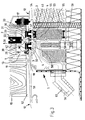
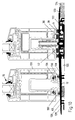
- Fig. 1 the sliding element according to the invention is shown in a view.
- the sliding element 1 is arranged here on the right side of a wall opening 10, on the left next to it a fixed element 15 is arranged.
- a fixed element 15 Schematically indicated, the door fittings 22, 22 'can be seen.
- the door fittings 22, 22 ' are moved by the opening handle 14 so that they are moved similarly up or down.
- the wall opening 10 is provided in the wall 16.
- the sliding element 1, as well as the fixed element 15 are based on the support 12 and the bottom 12 from. As already stated, the terms support and ground are synonymous to understand.
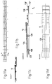
- Fig. 2 it is indicated that the sliding element 1 by the sliding movement 11 to the left is movable so as to open the wall opening 10 at least partially.
- the sliding element 1 By a movement of the sliding element 1 to the right, the wall opening 10 is completely closed, in cooperation with the fixed element 15.
- the sliding element 1 it is possible to dispense with the arrangement of a fixed element 15. In this embodiment, then, the sliding element 1 would close or release the entire wall opening 10.
- the sealing element 3 is inserted in a provided on the bottom or in the support 12 groove-like 40 receiving profile 4.
- the sealing element 3 cooperates with a magnetic counterpart 30, which is arranged, for example, on the lower edge 19 of the sliding element.
- the magnetic counterpart part 30 is arranged on a support bar 21 arranged on the underside of the sliding element 1.
- Magnetalleteil 30 and sealing element 3 in opposition such that the magnetic forces act in an ideal manner, wherein the magnetic forces are greater than the gravity of the sealing element 3 and thus cause an attraction, which lead to a sealing of the gap 18.
- the groove 40 of the receiving profile 4 has no over the entire groove height vertically extending groove walls. At its upper end inwardly standing stop strips 41, 42 are provided. These act together with outboard stop leg 32 of the otherwise U-shaped sealing element 3.
- the U-shaped sealing element 3 is inserted in the groove 40 so that the opening of the U is down.
- the arrangement is chosen so that, for example, the left stop bar 41 is integrally connected to the receiving profile 4. But it is also possible to provide a removable stop bar 42, which is provided in the example shown in FIG. 3 at the same time for the left and right sealing element 3.
- the stop bar 42 is fastened by corresponding threaded screws in the receiving profile 4. Conveniently serves in this embodiment, a stop bar 42 for two sealing elements.
- a foam coating 33 is optionally provided either on the leg of the U-shaped sealing element 3 or on the magnetic counterpart 30. At the same time, this foam coating 33 also effects the formation of a small spacer that does not hinder the tightness, which facilitates the separation of the sealing element 3 from the magnetic counterpart part 30 in the case of the opening of the sliding element 1. In this respect, the foam coating 33 is part of the sealing element 3 or of the magnetic opposite part 31.
- a separating device 2 which serves to separate the sealing element 3 from the magnetic counterpart part 30.
- the separating device 2 is formed in the embodiment shown here by a support beam 21, which is arranged at the lower edge 19 of the sliding element 1 in a recess 13. This support beam 21 carries in the embodiment shown here, the magnetic counter parts 30th
- the support bar 21 is connected to the door fitting 22.
- the door fitting 22 is, for example, a commercially available door hinge which, for example, serves to drive locking bolts and so on. Instead of a door hinge but also appropriate pull or operating rods are used. In general, these force-transmitting elements are described and characterized as door fittings 22 in the context of this invention.
- the door fitting 22 is connected at the lateral ends of the support beam 21 thereto. This is done, for example, by the indicated fastening screw.
- the arrangement is chosen so that the depth of the recess 13 is greater than the thickness of the support beam 21. This means that the support bar 21 in the recess 13 can move upwards, vertically and retreat. Since the magnetic counter parts 30 are located at its lower edge, a mechanism is thus provided which serves to remove or separate the magnetic counterpart part 30 from the sealing element 3.
- the necessary vertical movement 20 is impressed on the support beam 1 by the door fitting 22, 22 '. Reference is made to FIG. 1.
- the opening handle 14 also acts on the door fittings 22, 22 '.
- the opening handle 14 is indicated in two positions. In the first, excellent position, the closed position is executed. In this case, the opening handle 14 is vertical. In the second, dashed lines indicated position of the opening handle 14 is rotated by 90 ° in the horizontal.
- the open position of the opening handle 14 ' communicates with the upper layer of the support beam 21', which is also shown in dashed lines.
- the lower position of the excellent support beam 21 communicates with the perpendicular opening handle 14.
- the training is chosen so that a similar movement of the door fittings 22, 22 'is provided at the various lateral ends of the support beam 21 due to the movement of the opening handle 14.
- a corresponding conversion gear is provided in order to ensure that the right 22 and left 22 'part of the door fittings each move in the same direction, ie evenly up or evenly down.
- the operation of the opening handle 14 for opening the sliding element 1, the separation device 2 for separating the sealing element 3 from the Magnetumbleteil 30 provides.
- the separating device 2 raises the magnetic opposite part 30 indirectly or directly until the adhering to the Magnetalleteil 30 by the magnetic forces sealing element 3 rests against the stop bar 42, 41. Further movement of the Magnetalleers 30 then leads to the formation of an air gap between the Magnetalleteil 30 and the sealing element 3. Since the distance between the two magnetic parts increases and the effectiveness of the magnetic forces with increasing Distance decreases, then drops the heavier sealing element 3 in the groove 40 down and the magnetic element 30 is free of the sealing element. 3
- the support beam 21 still carries on its outer side a pinch seal 31.
- This pinch seal acts as an additional sealing level.
- the receiving profile 4 is part of a dewatering device 5.
- This advantageous embodiment ensures that a reliable, powerful, magnetic-force-based sealing is also available for firedamp impacted sliding elements available.
- the dewatering device ensures that water present on the sliding element is discharged downwards.
- the groove 40 of the receiving profile 4 has drainage channels 50. Water that passes behind the pinch seal 31 will initially enter the groove 40. It is favorable that no complete fit of the sealing element 3 is provided in the groove 40 in order to provide a space for the drainage of water. Water that collects in the groove 40 is then drained through drainage channels 50 located in the bottom, as indicated by the dotted line 56.
- the third sealing plane which is formed by the second sealing element (the right sealing element 3)
- the design of the sealing element 3 is the same as that of the first, left-hand sealing element 3.
- the drainage channels are not in the bottom of the groove 40 but in the groove portion of the groove wall.
- the embodiment according to the invention therefore represents a drainage system formed by three different sealing levels.
- the applicant reserves the right to request independent protection for the special design of this drainage device in connection with the use in sliding elements.
- a hose can serve, which can be plugged onto the nozzle 57. This makes it possible to direct incoming water from the wall opening far away to a drainage or discharge or the like.
- the invention provides that the dewatering device 5 at the top has a on the outside of the wall opening 10 extending tread 51.
- the design of this treadplate increases the stability of the entire arrangement.
- the receiving profile 4 is integrally connected to the tread bar 51 in the right area.
- the receiving profile 4 is made with the tread 51 for example of aluminum in an extrusion process. It is envisaged that the tread bar 51 extends over the entire width of the opening 10 (see FIG. 2) and thus extends below the fixed element 15.
- a fixed element 15 is supported on the tread bar 51 via a compensating lining 52.
- the compensating lining 52 is arranged, for example, on the underside of the fixed element.
- the Austiciansunter spatt für 52 is wider than the width of the fixed element 15. It has on the inside, in the displacement region of the sliding element 1, a guide spring 53 for the open sliding element 1 on. Conveniently, this guide spring 53 cooperates with the corresponding groove, which is provided on the underside 19 of the sliding element 1.
- the support beam 21 carries a downwardly open guide groove 23 in order to cooperate with the guide spring 53.
- the tread bar 51 is arranged on the outside. However, the dewatering device 5 also extends a little way into the interior, so as to form a channel 54, on which one or more support wheels 17 of the sliding element 1 find a guide.
- the dewatering device 5 is formed in two or more parts. Conveniently, at least two parts of the dewatering device 5 are connected to one another by one or more insulating webs 55. These are for example Double T-shaped (below) or E-like (top) arranged in Fig. 3 below the right sealing element 3. Intermediate spaces are filled with appropriate insulation material.
- the insulating bars are characterized by a poor heat conductive material particularly.
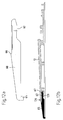
- FIG. 4 shows the detail of a further embodiment of a sliding element 1 according to the invention corresponding to FIG. 3.
- the same parts are provided with the same reference numerals as in Fig. 3.
- Parts of the dewatering device 5, which have already been described with the figure description of Fig. 3, have been omitted for the sake of simplicity.
- the embodiment of the sliding element according to FIG. 4 represents the lower part of the sliding element with guide rollers mounted on top.
- the upper end of the sliding element is not shown.
- the sliding element is guided with its upper guide rollers in a rail, for example, a Schwebetenaufhfitung. Between the lower edge of the sliding element and the support remains a gap which is closed by the magnetic seal.
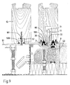
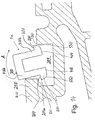
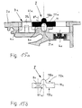
- FIG. 9 shows a further variant of the invention.
- the structure is substantially similar to that of FIG. 3, which is why, to avoid repetition, only the different features are specifically highlighted.
- Essential in this variant, as well as in the other variants of FIG. 5 to 7 is that the support wheel 17 in the profile of the sliding element is centrally installed and not laterally located next to it, as indicated for example in Fig. 3.
- the support wheel 17 rolls off on the stop bar 42, which is arranged between the two sealing elements 3, 3 '.
- the wheel 17 in this case has a circumferential cam 71, which is designed like a ring and engages in a recess 72 of the stop bar 42.
- the stop bar 42 is connected by a fastening screw 80 with the receiving profile 4.
- openings 8 are provided.
- the Magnet literallyteil 30 is seen in section as an inverted T formed.
- the upstanding stem engages a pin-like manner in a groove 100 on the underside of the sliding element 1. Assembly and alignment is greatly facilitated.
- a thin spacer for example made of sponge rubber, plastic or the like.
- this edition also acts as a seal, as it has a certain elasticity.
- This compensating lining 52 is also formed inverted T-like and engages in a groove 101 on the underside of the fixed element 15 a.
- a seal 500 is provided, which in particular ensures that possibly occurring dimensional inaccuracies or shrinkage does not lead to leaks.
- a positioning means is skillfully provided on the compensating lining 52, which cooperates with a positioning means of the tread 51.
- This makes it possible to facilitate the alignment of the Ausretesunter Stahltt für satusky satusky satusky satusky satusky satusky satusky satusky satusky satusky satusky satusky satsky , etc.
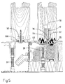
- a similar structure as shown in Fig. 9 is shown.
- the sliding element 1 according to the invention is designed here as a wooden component.
- the components are installed in corresponding milled grooves.
- the wheel 17 has a circumferential groove 70 which cooperates with a survey 73 of the stop bar 42.
- the stop bar 42 is in a receptacle 37, which is groove-like incorporated in the receiving profile 4, used.
- the receptacle 4 for example, a positioning spring 36 which cooperates with a positioning groove 35 of the stop bar 42.
- the transverse extent of the receiving profile is considerable, so favorably in the direction from the inside to the outside (transverse to the longitudinal extension of the receiving profile 4) several, for example, two Abatweilfeine 59 use. Since several feet are arranged along the longitudinal extension of the receiving profile, a table-like storage results.
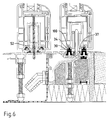
- the sliding element according to the invention is designed as a plastic component. Between the Magnetumbleteil 30, which is inserted into the groove 100 of the sliding element, an adapter profile 34 is provided.
- the fixed element 15 is, as shown for example in Fig. 7, fixed by a fastening screw 58 either from top to bottom or from bottom to top.
- Fig. 7 shows the variant in which the wheel 17 has a circumferential groove 70 and the stop bar 42 has a survey 43 on which the wheel 17 is guided and controlled rolls.
- Fig. 8 an enlarged detail of the stop bar 42 is shown in Fig. 8 in cross section.
- a survey 73 which is suitable to cooperate with a circumferential groove.
- the bar is reversed, so is the recess 72 above, which is used for rollers with circumferential cams.
- the arrangement is chosen so that the mounting opening 8 can be used on the left side for both cases of use, as well as the two positioning grooves 35, 35 '. Therefore, the stop bar is not about its longitudinal axis to rotate, but about its transverse axis.
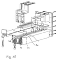
- Fig. 9, 10 a further inventive variant of the embodiment of the sliding element is shown.
- the variant according to FIG. 9, 10 is e.g. used when it can be dispensed with a correspondingly expensive drainage, which is installed in the floor.
- a floor covering 124 rests on the raw floor 125.
- the raw floor 125 has no recesses or heels in the region of the sliding element 1. It is good to see that the entire height of the support 12 is relatively low.
- the edition shown here and also belonging to the invention consists of several interacting elements.
- an embodiment of the support 12 is also described in more detail with reference to the figures 11a to 11d.
- the support 12 has a substantially flat area 126.
- the grooves 40 for receiving the receiving profile 4. In the right area of the support 12 are the grooves 40 for receiving the receiving profile 4. The arrangement is chosen so that two sealing elements are provided.
- the support 12 is followed by a thinner end region 127.
- This end region 127 is thinner relative to the flat, left region and is therefore at a lower height level. This is so realized so that above the end portion 127 a Verbinduzigsang 122 can be connected, which then carries on the other side another part 123 of the edition.
- the connecting power 122 is designed as an insulating piece and thus forms a heat or sound insulation.
- the entire height of the support is matched to the height of the floor covering 124. Therefore, it is possible to form the pad portion 123 on the floor pad 124, thereby concealing small gaps, etc. in the connection of the floor panel.
- the support 12 is in the lying on the outside, flat portion 126 and the inner, in particular the recesses having area on.
- the stop bar 42 which is removable at any time.
- the upper edge of the sealing strip also communicates with the upper edge of the support part 123 or in the flat region 126.
- latching elements 128, 128 ' are provided on the end portion 127 to connect to the connector 122.
- the variant according to the invention shown here sits on a bottom plate 6 arranged underneath.
- the bottom plate extends over almost the same surface area as the Pad 12, only in the right, inner area, the bottom plate 6 is shortened so as not to collide with the floor covering 24.
- the essential advantage of the bottom plate 6 is that a definerter water drainage channel 120 is available and the running water does not stand up on the Rohfuß founded 125. It is possible to choose the arrangement so that there is a defined gradient in the bottom plate 6 in order to reliably dissipate the moisture or water.
- a drainage channel 50 is provided in the support. This drains the penetrating into the receiving groove 40 water forward on the bottom plate. 6
- Transverse to the longitudinal extent of the support transverse channels 120 are provided in the support 2 in order to be able to derive the water forward.
- holding means 121 are provided to connect the support 12 and the bottom plate 6 together.
- these holding means 121 are formed as clip connections or as upwardly projecting, engaging hooks.
- corresponding hooks are integrally formed on the bottom plate 6, which engage with corresponding projections forming recesses 128 of the support 12 and hold latching there.
- a plurality of holding means 121 are arranged one behind the other in transverse extension of the support (from the inside to the outside) of the rest 12 (next to each other in section).
- corresponding holding means 121 provided to produce a reliable connection between the support 12 and the bottom plate 6.
- an end piece 60 connects on the bottom plate 6 on the outside.
- the end piece 60 is provided with a clip connection 62 which cooperates with locking lugs 129 on the support 12 such that a firm connection results.
- the arrangement is chosen so that the tail 60 Wasserableitkanäle 61 which communicate with the transverse channel 120 and direct the water guided thereby further out.
- the thickness of the underside of the end piece 60 corresponds to the thickness of the bottom plate 6.
- Fig. 11d shows a bottom view of the overlay 12, e.g. is shown in section in Fig. 11c.
- the transverse channel 120 extends from the outside to the region of the inner, second sealing element 3 and also drains this channel, if moisture or water should penetrate here.
- the cross channel 120 is e.g. created by a machining.
- pinch seals are described, wherein between the pinch seals 38 one or two sealing elements 3, as described, are arranged.
- the pinch seal 38 is arranged between the sealing elements 3.
- a plurality of sealing planes arranged one behind the other (from outside to inside) and thus a labyrinth effect thus result.
- Fig. 10 In Fig. 10, almost the same situation is shown as in Fig. 9, except that no bottom plate 6 is used here.
- the invention is therefore also directly on a Rohfußêt 125 erectable.
- the support 12 is the same as that used in FIG. 9. The invention is thus very variable.
- the support 12 is supported, for example, via the webs 125 forming the recess 128 on the unfinished floor 125.
- a support piece 63 is provided under the support 12. This can of course also be used in the arrangement with a bottom plate 6 use.
- the fixed sliding element 15 (drawn here on the left), has on an underside an attachment profile 132, through which the fixed element 15 rests on the support 12. Between the attachment profile 132 and the support 12 seals 130 are provided.
- the attachment profile 132 is pushed and clipped on the underside of the fixed element 15 at this.
- the seal 131 seals the gap between the attachment profile 132 and the frame part 133 of the fixed element 15.
- Fig. 12a, 12b the end piece 60 is still shown.
- the arrangement is chosen so that the surface of the flat area 126 opens without significant shoulder, as flush or steadily as possible in the surface 65 of the end piece 60. Therefore, a small shoulder 66 forms on the end piece 60, approximately in the middle, to form the connection area for the support 12. Further outward with respect to this paragraph (on the right) is followed by the clip connection 62, in which case the end piece 60 has a projecting tongue 67 which cooperates with the locking lugs 129 of the support 12.
- the magnetic strip according to the invention la in side view - from the front side - shown.
- the magnetic strip la consists according to this embodiment of a U-shaped profile body 700, the transverse web 700a is oriented upward and the legs 700b extend downwards. Quersteg 700a and leg 700b form a recess 601.
- the recess for saving material is provided.
- the magnetic strip 1a is entirely made of a magnetic material, so that the magnetic strip 1a is attracted to the action of magnetic forces.
- the profile body 700 consists of a sealing material such as rubber, plastic, Teflon or the like, wherein the magnetic element in the form of individual magnets or a magnetic profile can be inserted into the recess.
- the magnetic strip now consists of the non-magnetic profile body and a magnetic element.
- a projection 200 is provided at the lower ends of the legs 700 b, each directed toward the outside.
- This projection is formed by an upwardly directed flat surface 300 and a curve 550 extending from the flat surface to the lower end of the magnetic strip 1a.
- This rounding 550 may also be bounded below by a flat surface 400. Plane surface 300 and rounding 550 form a line 800.
- FIG. 14 the detail of a bottom rail 900 according to the invention is shown with a magnetic strip la.
- These Magnetic strip 1a is currently displayed in a state as it is inserted into the receiving profile 201 of the bottom rail 900.
- the left side of the recess 201 has an undercut 10a.
- the magnetic strip 1a is inserted with its left protrusion 200 under a fixed to the bottom rail stop bar 250 and aligned by a pivoting movement in the direction of arrow A in a vertical direction.
- the right projection 200 slides with its rounding 550 over the upper boundary edge 130 of the receiving profile 201.
- the magnetic strip la is deposited on the bottom of the receiving profile 201, wherein it comes to rest with the front ends 400 of the legs 700b on the bottom of the receiving profile 201.
- a releasable stop bar (not shown) is connected to the bottom rail 900 on the right side of the receiving profile 201, so that the right projection 200 forms an upwardly limiting stop.
- the magnetiaiste 1a is fixed in the receiving profile 201 of the bottom rail 900.
- the movement is bounded above by the stop bars 250 and down through the bottom of the receiving profile 201.
- the line 800 formed by the flat surface 300 and rounding 550 the magnetic strip slides along the side walls of the receiving profile. Due to the small contact surface, the friction of the magnetic strip is reduced to the receiving profile.
- an advantage of the rounding 550 is that even with a non-rectilinear movement, the magnetic strip 1a in the receiving profile 201 does not tilt.
- Fig. 15a shows a section through an arrangement with a roller guide I and the part of a bottom rail 2a.
- the roller guide I is designed as a profile strip 11a.
- the profile strip has an elevation 110a in its center and a groove 111a on the opposite side.
- a recess 21a is provided in the bottom rail 2a, which serves to ensure that in the event that the profile strip by 180 ° should be installed rotated, the increase 110a can be recorded there.
- a magnet 31a is designed as a magnetic strip for this purpose.
- the reference numeral 8a indicates a hole in the profile strip 11a, which is recessed, for example, and which serves to receive a countersunk screw, not shown.
- the countersunk screw is guided for fastening the profile strip through the bore 8a and screwed into a threaded hole 6a in the bottom rail 2a and thereby the profile strip 11a connected to the bottom rail 2a.
- the sealing element is indicated schematically.
- the sealing element 3a is formed from the magnet 31a and the magnetic opposite part 32a, not shown here.
- Fig. 15b shows a section through a profiled strip 11a.
- the arrow indicates that the roller guide is shown in its execution as a profile strip 11a.
- the increase 110a is used to guide not yet shown roles a sliding door or a sliding window.
- Such rollers may be formed either convex or cokaved at its outer radius in cross-section. For this reason, the invention proposes to make the roller guide I such that it makes both variants technically feasible without much effort. If, for example, a roller is concave, the roller guide I is installed in the illustrated form according to FIGS. 15a and 15b. The role is thus performed safely and can not dodge to the left or right.
- the roller guide I denotes the opening, through which the fastening means, for example a countersunk head screw is guided.
- the opening 8a is sunk on both sides, so there a countersunk screw in it can also be easily, without forming a resistance to the rollers, can be sunk.
- Reference numerals 112a and 113a designate guide grooves within which the wheel or the roller can additionally be guided. Cleverly, the distance of the guide grooves is selected so that spaced apart in its center, the openings 8a provided can wertden. If you then screwed the countersunk screws so that their slot is formed corresponding to the guide rollers, a guide is easily guaranteed on both sides.
- Fig. 16 shows an embodiment of a sliding element II with bottom rail 2a and roller guide I according to the invention.
- the sliding element II is designed as a sliding door or sliding window.
- the movable part of the sliding element II acts together with a bottom rail 2a, the sealing element 3a, consisting of magnets 31a and provided with the sliding element II Magnetismus kind 32a, for sealing together.
- the bottom rail 2a is also shown in section, as the sliding element II.
- a recess is milled, in which a support wheel 17a, which is seen for example as a roller with the cross-section convex outer edges.
- To guide the sliding element II serves the roller guide I, which is formed in the illustrated variant as a profile strip 11a.
- Fig. 17 differs from Fig. 16 only in that now the groove 111a facing down and the elevation 110a upwards.
- the support wheel 17a has a concave outer contour. Due to the interaction with the profile bar 11a, which is now arranged the other way round, a sufficiently stable guidance is ensured here as well. All other features have already been presented in the description of FIG. The reference numerals are used in the same way.
- Fig. 18 shows a three-dimensional view of a bottom rail 2a with a roller guide I according to the invention. Due to the three-dimensional representation is very well seen that the roller guide I is designed as a profile strip 11a, which can be produced very well and inexpensively, for example, in the strand, pressing or drawing process.
- the profiled strip 11a according to the invention is also provided as a completion element for the floor rail according to the invention, in particular for floor rails with magnetic seals.
- the roller guide 11a serves at the same time in each case inwardly facing completion of the grooves 4a, whereby the magnets, not shown, are guided safely in this guide.
- the profiled strip 11a is attached to the bottom rail 2a.
- the screws can be unscrewed and the profile strip can be removed. This allows, for example, to achieve a simpler and overall more favorable cleaning when the grooves 4a become dirty.
Applications Claiming Priority (6)
| Application Number | Priority Date | Filing Date | Title |
|---|---|---|---|
| DE102004038995 | 2004-08-10 | ||
| DE102004044060 | 2004-09-11 | ||
| DE102005002121 | 2005-01-14 | ||
| DE102005035222A DE102005035222A1 (de) | 2004-08-10 | 2005-07-25 | Rollenführung |
| DE102005035221A DE102005035221A1 (de) | 2004-08-10 | 2005-07-25 | Magnetleiste |
| DE102005035220A DE102005035220A1 (de) | 2004-08-10 | 2005-07-25 | Schiebeelement |
Publications (1)
| Publication Number | Publication Date |
|---|---|
| EP1626148A2 true EP1626148A2 (fr) | 2006-02-15 |
Family
ID=35395752
Family Applications (1)
| Application Number | Title | Priority Date | Filing Date |
|---|---|---|---|
| EP20050017378 Withdrawn EP1626148A2 (fr) | 2004-08-10 | 2005-08-10 | Elément coulissant |
Country Status (1)
| Country | Link |
|---|---|
| EP (1) | EP1626148A2 (fr) |
Cited By (6)
| Publication number | Priority date | Publication date | Assignee | Title |
|---|---|---|---|---|
| EP2363563A3 (fr) * | 2010-03-02 | 2013-11-27 | Veka AG | Elément de montage pour un battant fixe d'une porte coulissante levante et système de profilé de porte coulissante |
| GB2502580A (en) * | 2012-05-31 | 2013-12-04 | Hl Plastics Ltd | A structural spacer member for a sliding door assembly |
| EP2573308A3 (fr) * | 2011-09-20 | 2016-10-12 | HAUTAU GmbH | Rail de guidage étanche pour porte coulissante (procédé et dispositif) |
| CN107724701A (zh) * | 2017-11-09 | 2018-02-23 | 中国建筑第八工程局有限公司 | 楼层放线孔的防护装置及其施工方法 |
| EP3502400A1 (fr) * | 2017-12-22 | 2019-06-26 | JOSKO Fenster und Türen GmbH | Agencement de porte coulissante destiné à la séparation d'un intérieur d'un environnement extérieur |
| CN115478769A (zh) * | 2022-10-21 | 2022-12-16 | 九牧厨卫股份有限公司 | 一种带翻转挡水条的淋浴房移门 |
Citations (1)
| Publication number | Priority date | Publication date | Assignee | Title |
|---|---|---|---|---|
| DE19732352A1 (de) | 1997-07-28 | 1999-02-04 | Harry Frey | Magnetdichtung für Türen, Fenster und dergleichen |
-
2005
- 2005-08-10 EP EP20050017378 patent/EP1626148A2/fr not_active Withdrawn
Patent Citations (1)
| Publication number | Priority date | Publication date | Assignee | Title |
|---|---|---|---|---|
| DE19732352A1 (de) | 1997-07-28 | 1999-02-04 | Harry Frey | Magnetdichtung für Türen, Fenster und dergleichen |
Cited By (8)
| Publication number | Priority date | Publication date | Assignee | Title |
|---|---|---|---|---|
| EP2363563A3 (fr) * | 2010-03-02 | 2013-11-27 | Veka AG | Elément de montage pour un battant fixe d'une porte coulissante levante et système de profilé de porte coulissante |
| EP2573308A3 (fr) * | 2011-09-20 | 2016-10-12 | HAUTAU GmbH | Rail de guidage étanche pour porte coulissante (procédé et dispositif) |
| GB2502580A (en) * | 2012-05-31 | 2013-12-04 | Hl Plastics Ltd | A structural spacer member for a sliding door assembly |
| GB2502580B (en) * | 2012-05-31 | 2017-11-01 | Hl Plastics Ltd | A structural spacing member |
| CN107724701A (zh) * | 2017-11-09 | 2018-02-23 | 中国建筑第八工程局有限公司 | 楼层放线孔的防护装置及其施工方法 |
| EP3502400A1 (fr) * | 2017-12-22 | 2019-06-26 | JOSKO Fenster und Türen GmbH | Agencement de porte coulissante destiné à la séparation d'un intérieur d'un environnement extérieur |
| CN115478769A (zh) * | 2022-10-21 | 2022-12-16 | 九牧厨卫股份有限公司 | 一种带翻转挡水条的淋浴房移门 |
| CN115478769B (zh) * | 2022-10-21 | 2023-10-20 | 九牧厨卫股份有限公司 | 一种带翻转挡水条的淋浴房移门 |
Similar Documents
| Publication | Publication Date | Title |
|---|---|---|
| EP2685039B1 (fr) | Dispositif de guidage, chariot et rail de guidage | |
| EP3596295B1 (fr) | Système seuil pour battant mobile utilisé comme battant coulissant ou battant levant-coulissant mobile d'une fenêtre ou d'une porte | |
| EP3080375A2 (fr) | Dispositif destiné à fermer une ouverture dans un bâtiment | |
| EP1626148A2 (fr) | Elément coulissant | |
| EP3380692B1 (fr) | Dispositif de paroi coulissante avec élément de recouvrement | |
| EP3502401B1 (fr) | Plancher plate pour porte coulissante | |
| DE102005035220A1 (de) | Schiebeelement | |
| EP3488065A1 (fr) | Système seuil pour un battant mobile faisant office de battant coulissant ou un battant levant-coulissant mobile d'une fenêtre ou d'une porte | |
| DE102006007742A1 (de) | Bodenschwelle | |
| EP2317054B1 (fr) | Porte coulissante | |
| DE202013100864U1 (de) | Bodenschiene | |
| EP2157898B1 (fr) | Porte coulissante et paroi de douche à porte coulissante | |
| DE102006013120B3 (de) | Mobile Trennwand | |
| DE19835684C2 (de) | Verfahrbare Türflügelanordnung | |
| EP3608494B1 (fr) | Dispositif de levage pour portes coulissantes ou fenêtres coulissantes | |
| DE102005035222A1 (de) | Rollenführung | |
| WO2020142854A1 (fr) | Seuil sans obstacle pour portes | |
| EP2400100B1 (fr) | Rail de guidage et châssis avec un tel rail de guidage | |
| CH672162A5 (en) | Wooden door glazing seal - has holding strip supported by blocks round periphery of glazing | |
| DE102015122312A1 (de) | Hebeschiebetür | |
| DE102018126659B4 (de) | Blendrahmenprofil für Türen und Fenster mit Zusatzkomponenten | |
| DE202012001124U1 (de) | Zusatzelement zum Anordnen an einer Bodenschwelle | |
| DE3119692A1 (de) | Vorfertigbares bauelement | |
| DE102017123074A1 (de) | Automatisches Türsystem, insbesondere in Form einer Schiebetür oder einer Teleskopschiebetür oder einer Falttür | |
| DE102006056652B4 (de) | Roll- oder Sektionaltor mit Bremse |
Legal Events
| Date | Code | Title | Description |
|---|---|---|---|
| PUAI | Public reference made under article 153(3) epc to a published international application that has entered the european phase |
Free format text: ORIGINAL CODE: 0009012 |
|
| AK | Designated contracting states |
Kind code of ref document: A2 Designated state(s): AT BE BG CH CY CZ DE DK EE ES FI FR GB GR HU IE IS IT LI LT LU LV MC NL PL PT RO SE SI SK TR |
|
| AX | Request for extension of the european patent |
Extension state: AL BA HR MK YU |
|
| STAA | Information on the status of an ep patent application or granted ep patent |
Free format text: STATUS: THE APPLICATION IS DEEMED TO BE WITHDRAWN |
|
| 18D | Application deemed to be withdrawn |
Effective date: 20090303 |