EP1626026A2 - Abdeckung für Umlenkrolle - Google Patents
Abdeckung für Umlenkrolle Download PDFInfo
- Publication number
- EP1626026A2 EP1626026A2 EP05107227A EP05107227A EP1626026A2 EP 1626026 A2 EP1626026 A2 EP 1626026A2 EP 05107227 A EP05107227 A EP 05107227A EP 05107227 A EP05107227 A EP 05107227A EP 1626026 A2 EP1626026 A2 EP 1626026A2
- Authority
- EP
- European Patent Office
- Prior art keywords
- cover
- roller
- elevator
- counterweight
- deflection roller
- Prior art date
- Legal status (The legal status is an assumption and is not a legal conclusion. Google has not performed a legal analysis and makes no representation as to the accuracy of the status listed.)
- Granted
Links
- 239000003380 propellant Substances 0.000 claims description 10
- 238000012423 maintenance Methods 0.000 description 3
- CYRMSUTZVYGINF-UHFFFAOYSA-N trichlorofluoromethane Chemical compound FC(Cl)(Cl)Cl CYRMSUTZVYGINF-UHFFFAOYSA-N 0.000 description 3
- 239000000872 buffer Substances 0.000 description 2
- 239000004604 Blowing Agent Substances 0.000 description 1
- 230000001133 acceleration Effects 0.000 description 1
- 238000007664 blowing Methods 0.000 description 1
- 238000010276 construction Methods 0.000 description 1
- 230000001419 dependent effect Effects 0.000 description 1
- 238000011161 development Methods 0.000 description 1
- 230000018109 developmental process Effects 0.000 description 1
- 230000000694 effects Effects 0.000 description 1
- 238000003780 insertion Methods 0.000 description 1
- 230000037431 insertion Effects 0.000 description 1
- 238000009434 installation Methods 0.000 description 1
- 238000010409 ironing Methods 0.000 description 1
- 238000004519 manufacturing process Methods 0.000 description 1
Images


Classifications
-
- B—PERFORMING OPERATIONS; TRANSPORTING
- B66—HOISTING; LIFTING; HAULING
- B66B—ELEVATORS; ESCALATORS OR MOVING WALKWAYS
- B66B11/00—Main component parts of lifts in, or associated with, buildings or other structures
- B66B11/02—Cages, i.e. cars
- B66B11/0226—Constructional features, e.g. walls assembly, decorative panels, comfort equipment, thermal or sound insulation
Definitions
- the invention relates to an elevator comprising an elevator car which can be moved in an elevator shaft and a counterweight, the elevator car and counterweight being connected by means of a carrying and driving means guided over deflection rollers and the deflection rollers being integrated in the elevator car or counterweight, wherein a drive drives the elevator car and drives the counterweight.
- a disadvantage of the known device is that the integrated in the elevator car or counterweight pulleys together with the incoming support and propellant for the maintenance personnel represent a significant risk.
- the invention aims to remedy this situation.
- the invention as characterized in the independent claims solves the problem of avoiding the disadvantages of the known device and to provide an elevator system that is safe for maintenance personnel.
- the advantages achieved by the invention are to be seen essentially in the fact that the pulleys of the elevator car as well as the pulleys of the counterweight for maintenance personnel represent no unexpected sources of danger.
- the inventive device With the inventive device, the incoming and outgoing on the pulley support and propellant (rope, belt) is covered. Furthermore, it is prevented with the inventive device that, for example, in excessive acceleration or deceleration of the elevator car or the counterweight, the support and propellant may leave the pulley partially or completely. In addition, it is prevented with the inventive device that dirt and / or objects between pulley and carrying and propellant can get.
- the inventive device is inexpensive to manufacture and can be easily assembled.
- a designated 1 elevator is shown, consisting of a movable in an elevator shaft 2 elevator car 3 and a counterweight 4.
- the elevator car 3 is guided by means of a first guide rail 5 and by means of a second guide rail 6.
- the counterweight 4 is guided by means of a third guide rail 7 and by means of a fourth guide rail, not shown.
- the guide rails are supported in a shaft pit 8, wherein the vertical forces are conducted into the shaft pit 8.
- the guide rails 5,6,7 are connected with ironing not shown with the shaft wall.
- buffers 9 are arranged, on which buffer plates 10 of the elevator car 3 and the counterweight 4 can put on.
- a belt 11 for example a toothed belt or a belt with longitudinal ribs (V-ribbed belt), is provided with a 2: 1 belt guide.
- a mechanical linear drive 12 arranged on the second guide rail 6, for example in the shaft head 2.1 drives the belt 11 by one unit by means of a drive wheel 13, the elevator car 3 or the counterweight 4 moves by half a unit.
- the one end of the belt 11 is located at a first cable hinge point 14 and the second end of the belt 11 is disposed at a second cable hinge point 15.
- the belt 11 is guided via a first deflection roller 16 with roller axle 16.1 via a profile roller 17, via a second deflection roller 18 with roller axle 18.1, via a third deflection roller 19, via the drive wheel 13 and via a fourth deflection roller 20.
- the first guide roller 16, the second guide roller 18 and the profile roller 17 are integrated in the floor 21 of the elevator car 3, wherein the belt extends in a bottom channel 21.1.
- the first guide roller 16, the second guide roller 18 and the profile roller 17 may also be integrated in the ceiling of the elevator car 3, wherein the belt extends in a ceiling channel.
- the profile roller 17 can be omitted.
- the profile roller 17 has a toothing of the belt 11 corresponding toothing or the longitudinal ribs of the belt 11 corresponding grooving.
- the first guide roller 16 and the second guide roller 18 guide the belt 11 on the non-toothed side by means of frontally arranged flanges.
- the arranged on the second guide rail 6 third guide roller 19 is with its teeth in engagement with the toothed side of the belt 11 and has a brake for normal operation.
- the drive wheel 13 is with its teeth in engagement with the toothed side of the belt 11.
- Ablenkrollen 22 of the linear drive 12 increase the wrap angle of the belt 11 am Drive wheel 13. Not shown is the motor or the motors for the drive wheel 13.
- the fourth guide roller 20 is arranged in the counterweight and in construction comparable to the first guide roller 16 or the second guide roller 18th
- the pulleys 16,18 are each provided with a cover 23 shown schematically.
- the deflection roller 20 of the counterweight may also be provided with a cover 23.
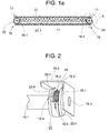
- the section A of Fig. 1a shows in Fig. 2, the guide roller 16 with the cover 23 in three-dimensional representation.
- the roller axle 16.1 is supported by a carrier designed as a U-profile 16.2.
- openings 16.3 are provided, engage in the lugs 23.1 of the side plates 23.4.
- the guide roller 16 has ribs 16.4 and grooves 16.5. Longitudinal ribs of the belt 11 fit between the ribs 16. 4 and into the grooves 16. 5 of the deflection roller 16.
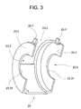
- FIG. 3 shows a three-dimensional representation of the hood-shaped cover 23, which has a first recess 23.2 and second recesses 23.3.
- the first recess 23.2 serves the inlet or the outlet of the carrying and propellant means 11.
- the second recesses 23.3 With the second recesses 23.3, the cover 23 fits on the roller axis 16.1.
- the second recesses 23.3 are circular, the circular arc 23.31 comprising the axis 16.1 by more than 180 °.
- the cover 23 is inserted at the lugs 23.1 as shown in FIG. 5 in the openings 16.3 of the U-profile 16.2 and resiliently locked with a rotational movement on the roller axle 16.1. With the arrangement of the cover 23 on the roller axle 16.1 the correct distance of the cover 23 to the guide roller 16,18,20 or to the carrying and propellant 11 is ensured in each case.
- Fig. 4 shows a section perpendicular to the roller axis 16.1.
- the circular arc of the side plates 23.4 include the axis 16.1 by more than 180 ° and ensure a resilient locking of the cover 23 with the roller axis 16.1.
- a designated 24 brush 24 prevents objects, garments, body parts or dirt, etc. between pulley 16,18,20 and carrying and propellant 11 can pass.
- the at least over the width of the support and propellant 11 extending brush 24 may be disposed on the cover 23 or on the carrier 16.2.
- Fig. 5 shows the introduction and locking of the lugs 23.1 in the openings 16.3 of the U-profile 16.2. With a broken line is shown as the nose 23.1 is inserted into the opening 16.3. At the end, the opening 16.3 has a widening, in which the nose 23.1 moves under the action of the spring action of the side plate 23.4. An arrow P1 symbolizes the insertion and Verrastvorgang the nose 23.1.
- Fig. 6 shows with hood-shaped covers 23 provided pulleys 20 of the counterweight 4, wherein the pulleys 20 are arranged on a yoke 4.1 of the counterweight 4.
- double guided belt 11 are provided, which are guided over the pulleys 20.
- the roller axle 20.1 and a bracket 25 are supported by a carrier 20.2 arranged on the yoke 4.1.
- the ends of the side plates 23.4 are provided with lugs which dip into recesses of the carrier 20.2.
- the covers 23 are mounted without tools and secured with the bracket 25.
- the cover 23 also serves as derailment protection.
- a staggered by a half longitudinal rib pitch belt 11 touches the side plates 23.4 and is forced by them back to its original position.
- a slacking belt 11 can not leave the roller grooves 16.5 with the cover 23 according to the invention.
- the offset during assembly in mechanical tension cover 23 can not generate rattling noises.
- the cover 23 is easily centered on the roller axle 16.1. On the roller axle 16.1,20.1 and grooves can be provided, in which the side plates 23 fit on the arc 23.31.
Abstract
Description
- Die Erfindung betrifft einen Aufzug bestehend aus einer in einem Aufzugsschacht verfahrbaren Aufzugskabine und einem Gegengewicht, wobei Aufzugskabine und Gegengewicht mittels eines über Umlenkrollen geführten Trag- und Treibmittels verbunden sind und die Umlenkrollen in der Aufzugskabine bzw. im Gegengewicht integriert sind, wobei ein Antrieb die Aufzugskabine und das Gegengewicht antreibt.
- Aus der Anmeldeschrift EP 04004311.9 ist ein Aufzug mit einer 2:1 Seilführung bekannt geworden, bei dem die Umlenkrollen der Aufzugskabine im Kabinenboden bzw. im Gegengewicht integriert sind. Das Trag- und Treibmittel wird im Kabinenboden durch einen Bodenkanal geführt. Gegenüber einem herkömmlichen Kabinenboden mit unterhalb angeordneten Umlenkrollen (Unterflaschen) baut der Kabinenboden gesamthaft in der Höhe sehr gering, was sich direkt auf die Schachtgrubentiefe auswirkt. Die mit dem Kabinenboden gewonnene Höhe kann in der Schachtgrubentiefe eingespart werden.
- Ein Nachteil der bekannten Einrichtung liegt darin, dass die in der Aufzugskabine bzw. im Gegengewicht integrierten Umlenkrollen zusammen mit dem einlaufenden Trag- und Treibmittel für das Unterhaltspersonal eine erhebliche Gefahr darstellen.
- Hier will die Erfindung Abhilfe schaffen. Die Erfindung, wie sie in den unabhängigen Ansprüchen gekennzeichnet ist, löst die Aufgabe, die Nachteile der bekannten Einrichtung zu vermeiden und eine Aufzugsanlage zu schaffen, die für Unterhaltspersonal sicher ist.
- Vorteilhafte Weiterbildungen der Erfindung sind in den abhängigen Patentansprüchen angegeben.
- Die durch die Erfindung erreichten Vorteile sind im wesentlichen darin zu sehen, dass die Umlenkrollen der Aufzugskabine wie auch die Umlenkrollen des Gegengewichtes für Unterhaltspersonal keine unerwarteten Gefahrenquellen darstellen. Mit der erfindungsgemässen Einrichtung wird das an der Umlenkrolle einlaufende bzw. auslaufende Trag- und Treibmittel (Seil, Riemen) abgedeckt. Im weiteren wird mit der erfindungsgemässen Einrichtung verhindert, dass beispielsweise bei übermässigen Beschleunigungen oder Verzögerungen der Aufzugskabine oder des Gegengewichts das Trag- und Treibmittel die Umlenkrolle teilweise oder vollständig verlassen kann. Ausserdem wird mit der erfindungsgemässen Einrichtung verhindert, dass Schmutz und/oder Gegenstände zwischen Umlenkrolle und Trag- und Treibmittel gelangen können. Die erfindungsgemässe Einrichtung ist billig in der Herstellung und kann einfach montiert werden.
- Anhand der beiliegenden Figuren wird die vorliegende Erfindung näher erläutert.
- Es zeigen:
- Fig. 1
einen Aufzug mit im Boden der Aufzugskabine integrierten Umlenkrollen, - Fig. 1a
einen Kabinenboden mit Umlenkrollen und der erfindungsgemässen Einrichtung, - Fig. 2
eine Umlenkrolle mit der erfindungsgemässen Einrichtung, - Fig. 3
eine dreidimensionale Darstellung einer Abdeckung, - Fig. 4 einen Schnitt rechtwinklig zur Achse der Umlenkrolle,
- Fig. 5
Einzelheiten der Abdeckung und - Fig. 6
mit Abdeckungen versehene Umlenkrollen des Gegengewichtes. - In Fig. 1 ist ein mit 1 bezeichneter Aufzug dargestellt, bestehend aus einer in einem Aufzugsschacht 2 verfahrbaren Aufzugskabine 3 und einem Gegengewicht 4. Die Aufzugskabine 3 wird mittels einer ersten Führungsschiene 5 und mittels einer zweiten Führungsschiene 6 geführt. Das Gegengewicht 4 wird mittels einer dritten Führungsschiene 7 und mittels einer vierten, nicht dargestellten Führungsschiene geführt. Die Führungsschienen sind in einer Schachtgrube 8 abgestützt, wobei die vertikalen Kräfte in die Schachtgrube 8 geleitet werden. Die Führungsschienen 5,6,7 sind mit nicht dargestellten Bügeln mit der Schachtwand verbunden. In der Schachtgrube 8 sind Puffer 9 angeordnet, auf denen Pufferplatten 10 der Aufzugskabine 3 bzw. das Gegengewicht 4 aufsetzen können.
- Als Trag- und Treibmittel ist ein Riemen 11, beispielsweise ein Zahnriemen oder ein Riemen mit Längsrippen (Keilrippenriemen), mit einer 2:1 Riemenführung vorgesehen. Wenn ein an der zweiten Führungsschiene 6, beispielsweise im Schachtkopf 2.1 angeordneter mechanischer Linearantrieb 12 den Riemen 11 mittels eines Antriebsrades 13 um eine Einheit vortreibt, bewegt sich die Aufzugskabine 3 bzw. das Gegengewicht 4 um eine halbe Einheit. Das eine Ende des Riemens 11 ist an einem ersten Seilfixpunkt 14 und das zweite Ende des Riemens 11 ist an einem zweiten Seilfixpunkt 15 angeordnet. Der Riemen 11 ist über eine erste Umlenkrolle 16 mit Rollenachse 16.1 über eine Profilrolle 17, über eine zweite Umlenkrolle 18 mit Rollenachse 18.1, über eine dritte Umlenkrolle 19, über das Antriebsrad 13 und über eine vierte Umlenkrolle 20 geführt. Die erste Umlenkrolle 16, die zweite Umlenkrolle 18 und die Profilrolle 17 sind im Boden 21 der Aufzugskabine 3 integriert, wobei der Riemen in einem Bodenkanal 21.1 verläuft. Die erste Umlenkrolle 16, die zweite Umlenkrolle 18 und die Profilrolle 17 können auch in der Decke der Aufzugskabine 3 integriert sein, wobei der Riemen in einem Deckenkanal verläuft. Wie im Ausführungsbeispiel der Fig. 1a kann die Profilrolle 17 weggelassen werden. Die Profilrolle 17 weist eine der Verzahnung des Riemens 11 entsprechende Verzahnung oder eine den Längsrippen des Riemens 11 entsprechende Rillung auf. Die erste Umlenkrolle 16 und die zweite Umlenkrolle 18 führen den Riemen 11 auf der nicht verzahnten Seite mittels stirnseitig angeordneten Flanschen. Die an der zweiten Führungsschiene 6 angeordnete dritte Umlenkrolle 19 steht mit ihrer Verzahnung im Eingriff mit der verzahnten Seite des Riemens 11 und weist eine Bremse für den Normalbetrieb auf. Das Antriebsrad 13 steht mit seiner Verzahnung im Eingriff mit der verzahnten Seite des Riemens 11. Ablenkrollen 22 des Linearantriebes 12 erhöhen den Umschlingungswinkel des Riemens 11 am Antriebsrad 13. Nicht dargestellt ist oder sind der Motor oder die Motoren für das Antriebsrad 13. Die vierte Umlenkrolle 20 ist im Gegengewicht angeordnet und im Aufbau vergleichbar mit der ersten Umlenkrolle 16 oder mit der zweiten Umlenkrolle 18.
- Wie in Fig. 1a gezeigt, sind die Umlenkrollen 16,18 je mit einer schematisch gezeigten Abdeckung 23 versehen. Die Umlenkrolle 20 des Gegengewichtes kann auch mit einer Abdeckung 23 versehen sein.
- Der Ausschnitt A der Fig. 1a zeigt in Fig. 2 die Umlenkrolle 16 mit der Abdeckung 23 in dreidimensionaler Darstellung. Die Rollenachse 16.1 wird von einem als U-Profil 16.2 ausgestalteten Träger getragen. Am U-Profil 16.2 sind Öffnungen 16.3 vorgesehen, in die Nasen 23.1 der Seitenschilder 23.4 einrasten. Die Umlenkrolle 16 weist Rippen 16.4 und Rillen 16.5 auf. Längsrippen des Riemens 11 passen zwischen die Rippen 16.4 und in die Rillen 16.5 der Umlenkrolle 16.
- Fig. 3 zeigt eine dreidimensionale Darstellung der haubenförmigen Abdeckung 23, die eine erste Ausnehmung 23.2 und zweite Ausnehmungen 23.3 aufweist. Die erste Ausnehmung 23.2 dient dem Einlauf bzw. dem Auslauf des Trag- und Treibmittels 11. Mit den zweiten Ausnehmungen 23.3 passt die Abdeckung 23 auf die Rollenachse 16.1. Die zweiten Ausnehmungen 23.3 sind kreisförmig, wobei der Kreisbogen 23.31 die Achse 16.1 um mehr als 180° umfasst. Zur werkzeuglosen Montage wird die Abdeckung 23 an den Nasen 23.1 gemäss Fig. 5 in die Öffnungen 16.3 des U-Profils 16.2 eingeführt und mit einer Drehbewegung an der Rollenachse 16.1 federnd verrastet. Mit der Anordnung der Abdeckung 23 an der Rollenachse 16.1 ist der korrekte Abstand der Abdeckung 23 zur Umlenkrolle 16,18,20 bzw. zum Trag- und Treibmittel 11 in jedem Fall gewährleistet.
- Fig. 4 zeigt einen Schnitt rechtwinklig zur Rollenachse 16.1. Die Kreisbogen der Seitenschilder 23.4 umfassen die Achse 16.1 um mehr als 180° und gewährleisten eine federnde Verrastung der Abdeckung 23 mit der Rollenachse 16.1. Eine mit 24 bezeichnete Bürste 24 verhindert, dass Gegenstände, Kleidungsstücke, Körperteile oder Schmutz, etc. zwischen Umlenkrolle 16,18,20 und Trag- und Treibmittel 11 gelangen können. Die sich mindestens über die Breite des Trag- und Treibmittels 11 erstreckende Bürste 24 kann an der Abdeckung 23 oder am Träger 16.2 angeordnet sein.
- Fig. 5 zeigt die Einführung und Verrastung der Nasen 23.1 in den Öffnungen 16.3 des U-Profils 16.2. Mit unterbrochener Linie ist gezeigt, wie die Nase 23.1 in die Öffnung 16.3 eingeführt wird. Am Ende weist die Öffnung 16.3 eine Verbreiterung auf, in die sich die Nase 23.1 unter Einwirkung der Federwirkung des Seitenschildes 23.4 bewegt. Ein Pfeil P1 symbolisiert den Einführ- und Verrastvorgang der Nase 23.1.
- Fig. 6 zeigt mit haubenförmigen Abdeckungen 23 versehene Umlenkrollen 20 des Gegengewichtes 4, wobei die Umlenkrollen 20 an einem Joch 4.1 des Gegengewichtes 4 angeordnet sind. Als Trag- und Treibmittel sind doppelt geführte Riemen 11 vorgesehen, die über die Umlenkrollen 20 geführt sind. Die Rollenachse 20.1 und ein Bügel 25 werden von einem am Joch 4.1 angeordneten Träger 20.2 getragen. Je Rolle 20 ist eine Abdeckung 23 vorgesehen, deren Kreisbogen der Seitenschilder 23.4 die Rollenachse 20.1 um mehr als 180° umfassen. Die Enden der Seitenschilder 23.4 sind mit Nasen versehen, die in Ausnehmungen des Trägers 20.2 eintauchen. Die Abdeckungen 23 werden werkzeuglos montiert und mit dem Bügel 25 gesichert.
- Die Abdeckung 23 dient auch als Entgleisungsschutz. Ein um eine halbe Längsrippenteilung versetzter Riemen 11 streift an den Seitenschildern 23.4 und wird von diesen wieder in seine Ursprungslage gezwungen. Ein schlaff werdender Riemen 11 kann mit der erfindungsgemässen Abdeckung 23 die Rollenrillen 16.5 nicht verlassen.
- Die bei der Montage in mechanische Spannung versetzte Abdeckung 23 kann keine Klappergeräusche erzeugen. Die Abdeckung 23 ist einfach auf der Rollenachse 16.1 zentrierbar. An der Rollenachse 16.1,20.1 können auch Nuten vorgesehen sein, in die die Seitenschilder 23 am Kreisbogen 23.31 passen.
Claims (7)
- Aufzug (1) bestehend aus einer in einem Aufzugsschacht (2) verfahrbaren Aufzugskabine (3) und einem Gegengewicht (4), wobei Aufzugskabine (3) und Gegengewicht (4) mittels eines über mindestens eine Umlenkrolle (16,18,20) geführten Trag- und Treibmittels (11) verbunden sind und die Umlenkrolle (16,18,20) in der Aufzugskabine (3) bzw. im Gegengewicht (4) integriert ist,
dadurch gekennzeichnet,
dass die Umlenkrolle (16,18,20) eine Abdeckung (23) aufweist, die das an der Umlenkrolle (16,18,20) einlaufende bzw. auslaufende Trag- und Treibmittel (11) abdeckt. - Aufzug nach Anspruch 1,
dadurch gekennzeichnet,
dass die Abdeckung (23) werkzeuglos an der Umlenkrolle (16,18,20) montierbar ist. - Aufzug nach einem der Ansprüche 1 oder 2,
dadurch gekennzeichnet,
dass die Abdeckung (23) haubenförmig ausgebildet ist und auf die Achse (16.1,20.1) der Umlenkrolle (16,18,20) passt. - Aufzug nach einem der vorhergehenden Ansprüche,
dadurch gekennzeichnet,
dass die Abdeckung (23) Nasen (23.1) aufweist, die in am Träger (16.2,20.2) der Umlenkrolle (16,18,20) angeordnete Öffnungen (16.3) passen und
dass die Abdeckung (23) Ausnehmungen (23.3) aufweist, die auf die Rollenachse (16.1,20.1) der Umlenkrolle (16,18,20) passen, wobei die Ausnehmungen (23.3) kreisförmig sind. - Aufzug nach einem der vorhergehenden Ansprüche,
dadurch gekennzeichnet,
dass eine am Träger (16.2,20.2) oder an der Abdeckung (23) angeordnete Bürste (24) vorgesehen ist, die sich mindestens über die Breite des Trag- und Treibmittels (11) erstreckt und verhindert, dass Gegenstände, Kleidungsstücke, Körperteile oder Schmutz, etc. zwischen Umlenkrolle (16,18,20) und Trag- und Treibmittel (11) gelangen können. - Verfahren zur Verbesserung der Sicherheit eines Aufzuges (1) bestehend aus einer in einem Aufzugsschacht (2) verfahrbaren Aufzugskabine (3) und einem Gegengewicht (4), wobei Aufzugskabine (3) und Gegengewicht (4) mittels eines über mindestens eine Umlenkrolle (16,18,20) geführten Trag- und Treibmittels (11) verbunden sind und die Umlenkrolle (16,18,20) in der Aufzugskabine (3) bzw. im Gegengewicht (4) integriert ist,
dadurch gekennzeichnet,
dass an der Umlenkrolle (16,18,20) eine Abdeckung (23) verrastbar ist, die das an der Umlenkrolle (16,18,20) einlaufende bzw. auslaufende Trag- und Treibmittel (11) abdeckt. - Aufzug nach Anspruch 6,
dadurch gekennzeichnet,
dass die Abdeckung (23) werkzeuglos an der Umlenkrolle (16,18,20) verrastbar ist.
Priority Applications (2)
| Application Number | Priority Date | Filing Date | Title |
|---|---|---|---|
| EP05107227A EP1626026B1 (de) | 2004-08-09 | 2005-08-05 | Abdeckung für Umlenkrolle |
| PL05107227T PL1626026T3 (pl) | 2004-08-09 | 2005-08-05 | Osłona krążka zwrotnego |
Applications Claiming Priority (2)
| Application Number | Priority Date | Filing Date | Title |
|---|---|---|---|
| EP04405503 | 2004-08-09 | ||
| EP05107227A EP1626026B1 (de) | 2004-08-09 | 2005-08-05 | Abdeckung für Umlenkrolle |
Publications (3)
| Publication Number | Publication Date |
|---|---|
| EP1626026A2 true EP1626026A2 (de) | 2006-02-15 |
| EP1626026A3 EP1626026A3 (de) | 2006-09-27 |
| EP1626026B1 EP1626026B1 (de) | 2010-03-03 |
Family
ID=35637335
Family Applications (1)
| Application Number | Title | Priority Date | Filing Date |
|---|---|---|---|
| EP05107227A Active EP1626026B1 (de) | 2004-08-09 | 2005-08-05 | Abdeckung für Umlenkrolle |
Country Status (2)
| Country | Link |
|---|---|
| EP (1) | EP1626026B1 (de) |
| PL (1) | PL1626026T3 (de) |
Cited By (5)
| Publication number | Priority date | Publication date | Assignee | Title |
|---|---|---|---|---|
| WO2014001372A1 (de) | 2012-06-29 | 2014-01-03 | Inventio Ag | Aufzugsanlage |
| DE202015105395U1 (de) | 2015-10-12 | 2015-11-16 | Aufzugteile Bt Gmbh | Fahrkorb für einen Aufzug in einem Aufzugsschacht |
| WO2017064123A1 (de) | 2015-10-12 | 2017-04-20 | Inventio Ag | Fahrkorb für einen aufzug in einem aufzugsschacht |
| US9884748B2 (en) | 2013-12-17 | 2018-02-06 | Inventio Ag | Elevator system |
| KR101995036B1 (ko) * | 2019-04-11 | 2019-07-02 | 그린엘리베이터(주) | 엘리베이터용 처짐 및 편심방지 시스템 |
Citations (4)
| Publication number | Priority date | Publication date | Assignee | Title |
|---|---|---|---|---|
| JPH02295878A (ja) * | 1989-05-10 | 1990-12-06 | Mitsubishi Electric Corp | エレベータの吊り車装置 |
| JPH05105365A (ja) * | 1991-10-18 | 1993-04-27 | Mitsubishi Denki Bill Techno Service Kk | エレベータ装置 |
| JPH09165165A (ja) * | 1995-12-19 | 1997-06-24 | Hitachi Building Syst Co Ltd | エレベータスチールテープの清掃器 |
| JP2003238050A (ja) * | 2002-02-08 | 2003-08-27 | Mitsubishi Electric Building Techno Service Co Ltd | エレベータロープのメンテナンス装置 |
-
2005
- 2005-08-05 PL PL05107227T patent/PL1626026T3/pl unknown
- 2005-08-05 EP EP05107227A patent/EP1626026B1/de active Active
Patent Citations (4)
| Publication number | Priority date | Publication date | Assignee | Title |
|---|---|---|---|---|
| JPH02295878A (ja) * | 1989-05-10 | 1990-12-06 | Mitsubishi Electric Corp | エレベータの吊り車装置 |
| JPH05105365A (ja) * | 1991-10-18 | 1993-04-27 | Mitsubishi Denki Bill Techno Service Kk | エレベータ装置 |
| JPH09165165A (ja) * | 1995-12-19 | 1997-06-24 | Hitachi Building Syst Co Ltd | エレベータスチールテープの清掃器 |
| JP2003238050A (ja) * | 2002-02-08 | 2003-08-27 | Mitsubishi Electric Building Techno Service Co Ltd | エレベータロープのメンテナンス装置 |
Non-Patent Citations (4)
| Title |
|---|
| PATENT ABSTRACTS OF JAPAN Bd. 015, Nr. 069 (M-1083), 19. Februar 1991 (1991-02-19) -& JP 02 295878 A (MITSUBISHI ELECTRIC CORP), 6. Dezember 1990 (1990-12-06) * |
| PATENT ABSTRACTS OF JAPAN Bd. 017, Nr. 459 (M-1467), 23. August 1993 (1993-08-23) -& JP 05 105365 A (MITSUBISHI DENKI BILL TECHNO SERVICE KK; others: 01), 27. April 1993 (1993-04-27) * |
| PATENT ABSTRACTS OF JAPAN Bd. 1997, Nr. 10, 31. Oktober 1997 (1997-10-31) & JP 09 165165 A (HITACHI BUILDING SYST CO LTD), 24. Juni 1997 (1997-06-24) * |
| PATENT ABSTRACTS OF JAPAN Bd. 2003, Nr. 12, 5. Dezember 2003 (2003-12-05) -& JP 2003 238050 A (MITSUBISHI ELECTRIC BUILDING TECHNO SERVICE CO LTD), 27. August 2003 (2003-08-27) * |
Cited By (9)
| Publication number | Priority date | Publication date | Assignee | Title |
|---|---|---|---|---|
| WO2014001372A1 (de) | 2012-06-29 | 2014-01-03 | Inventio Ag | Aufzugsanlage |
| CN104428231A (zh) * | 2012-06-29 | 2015-03-18 | 因温特奥股份公司 | 电梯设备 |
| CN104428231B (zh) * | 2012-06-29 | 2016-09-07 | 因温特奥股份公司 | 电梯设备 |
| US9522806B2 (en) | 2012-06-29 | 2016-12-20 | Inventio Ag | Deflection pulley cover for monitoring elevator car support |
| US9884748B2 (en) | 2013-12-17 | 2018-02-06 | Inventio Ag | Elevator system |
| DE202015105395U1 (de) | 2015-10-12 | 2015-11-16 | Aufzugteile Bt Gmbh | Fahrkorb für einen Aufzug in einem Aufzugsschacht |
| WO2017064123A1 (de) | 2015-10-12 | 2017-04-20 | Inventio Ag | Fahrkorb für einen aufzug in einem aufzugsschacht |
| US11180346B2 (en) | 2015-10-12 | 2021-11-23 | Inventio Ag | Car for an elevator in an elevator shaft |
| KR101995036B1 (ko) * | 2019-04-11 | 2019-07-02 | 그린엘리베이터(주) | 엘리베이터용 처짐 및 편심방지 시스템 |
Also Published As
| Publication number | Publication date |
|---|---|
| EP1626026B1 (de) | 2010-03-03 |
| EP1626026A3 (de) | 2006-09-27 |
| PL1626026T3 (pl) | 2010-07-30 |
Similar Documents
| Publication | Publication Date | Title |
|---|---|---|
| EP1400479B1 (de) | Antriebsmaschine für eine Aufzugsanlage und Verfahren zur Montage einer Antriebsmaschine | |
| EP1580156B1 (de) | Aufzug mit riemenartigem Übertragungsmittel, insbesondere mit Keilrippenriemen, als Tragmittel und/oder Treibmittel | |
| EP1448470B1 (de) | Aufzug mit riemenartigem übertragungsmittel, insbesondere mit zahnriemen, als tragmittel und/oder treibmittel | |
| EP1326797B2 (de) | Aufzug mit im aufzugsschacht oben seitlich angeordneter antriebseinheit | |
| EP1606208B1 (de) | Aufzug mit 2:1 zahnriemenführung | |
| EP1591404A2 (de) | Aufzugsanlage und Verfahren zur Anordnung einer Antriebsmaschine einer Aufzugsanlage | |
| EP1626026B1 (de) | Abdeckung für Umlenkrolle | |
| EP1457454B1 (de) | Aufzugskabine mit integrierten Umlenkrollen | |
| DE102006044669A1 (de) | Maschinenraumloser Treibkörperaufzug | |
| EP1656318B9 (de) | Verfahren zur Montage eines Aufzugs | |
| EP3114067B1 (de) | Antrieb mit mehrfach-umschlingung für eine aufzusanlage | |
| EP2014598A1 (de) | Antrieb für Vertikalaufzüge | |
| DE102006043198B3 (de) | Fahrzeugwaschanlage mit mehreren Behandlungsaggregaten | |
| WO2017167881A1 (de) | Führungsanordnung für eine aufzuganlage | |
| DE1198972B (de) | Seilaufzug | |
| EP1867597B1 (de) | Aufzug | |
| EP1197466A2 (de) | Aufzug mit oben im Schacht angeordneten Antrieb | |
| DE20319577U1 (de) | Maschinenaufnahmerahmen für triebwerksraumlosen Treibscheibenaufzug | |
| DE29908632U1 (de) | Maschinenraumloser Treibscheibenaufzug | |
| DE102005012137A1 (de) | Seilführung für einen Aufzug | |
| EP1588976A1 (de) | Aufzug für grosse Laten | |
| DE202004002281U1 (de) | Komplexe, modulare Aufzugskonfiguration für triebwerksraumlosen Treibscheibenaufzug | |
| DE202006014096U1 (de) | Fahrzeugwaschanlage mit mehreren Behandlungsaggregaten |
Legal Events
| Date | Code | Title | Description |
|---|---|---|---|
| PUAI | Public reference made under article 153(3) epc to a published international application that has entered the european phase |
Free format text: ORIGINAL CODE: 0009012 |
|
| AK | Designated contracting states |
Kind code of ref document: A2 Designated state(s): AT BE BG CH CY CZ DE DK EE ES FI FR GB GR HU IE IS IT LI LT LU LV MC NL PL PT RO SE SI SK TR |
|
| AX | Request for extension of the european patent |
Extension state: AL BA HR MK YU |
|
| PUAL | Search report despatched |
Free format text: ORIGINAL CODE: 0009013 |
|
| AK | Designated contracting states |
Kind code of ref document: A3 Designated state(s): AT BE BG CH CY CZ DE DK EE ES FI FR GB GR HU IE IS IT LI LT LU LV MC NL PL PT RO SE SI SK TR |
|
| AX | Request for extension of the european patent |
Extension state: AL BA HR MK YU |
|
| 17P | Request for examination filed |
Effective date: 20070310 |
|
| 17Q | First examination report despatched |
Effective date: 20070423 |
|
| AKX | Designation fees paid |
Designated state(s): AT BE BG CH CY CZ DE DK EE ES FI FR GB GR HU IE IS IT LI LT LU LV MC NL PL PT RO SE SI SK TR |
|
| GRAP | Despatch of communication of intention to grant a patent |
Free format text: ORIGINAL CODE: EPIDOSNIGR1 |
|
| GRAS | Grant fee paid |
Free format text: ORIGINAL CODE: EPIDOSNIGR3 |
|
| GRAA | (expected) grant |
Free format text: ORIGINAL CODE: 0009210 |
|
| AK | Designated contracting states |
Kind code of ref document: B1 Designated state(s): AT BE BG CH CY CZ DE DK EE ES FI FR GB GR HU IE IS IT LI LT LU LV MC NL PL PT RO SE SI SK TR |
|
| REG | Reference to a national code |
Ref country code: GB Ref legal event code: FG4D Free format text: NOT ENGLISH |
|
| REG | Reference to a national code |
Ref country code: CH Ref legal event code: EP |
|
| REG | Reference to a national code |
Ref country code: IE Ref legal event code: FG4D |
|
| REF | Corresponds to: |
Ref document number: 502005009120 Country of ref document: DE Date of ref document: 20100415 Kind code of ref document: P |
|
| REG | Reference to a national code |
Ref country code: PT Ref legal event code: SC4A Free format text: AVAILABILITY OF NATIONAL TRANSLATION Effective date: 20100525 |
|
| REG | Reference to a national code |
Ref country code: NL Ref legal event code: T3 |
|
| REG | Reference to a national code |
Ref country code: ES Ref legal event code: FG2A Ref document number: 2341780 Country of ref document: ES Kind code of ref document: T3 |
|
| PG25 | Lapsed in a contracting state [announced via postgrant information from national office to epo] |
Ref country code: LT Free format text: LAPSE BECAUSE OF FAILURE TO SUBMIT A TRANSLATION OF THE DESCRIPTION OR TO PAY THE FEE WITHIN THE PRESCRIBED TIME-LIMIT Effective date: 20100303 |
|
| REG | Reference to a national code |
Ref country code: PL Ref legal event code: T3 |
|
| LTIE | Lt: invalidation of european patent or patent extension |
Effective date: 20100303 |
|
| PG25 | Lapsed in a contracting state [announced via postgrant information from national office to epo] |
Ref country code: SI Free format text: LAPSE BECAUSE OF FAILURE TO SUBMIT A TRANSLATION OF THE DESCRIPTION OR TO PAY THE FEE WITHIN THE PRESCRIBED TIME-LIMIT Effective date: 20100303 Ref country code: LV Free format text: LAPSE BECAUSE OF FAILURE TO SUBMIT A TRANSLATION OF THE DESCRIPTION OR TO PAY THE FEE WITHIN THE PRESCRIBED TIME-LIMIT Effective date: 20100303 |
|
| REG | Reference to a national code |
Ref country code: IE Ref legal event code: FD4D |
|
| PG25 | Lapsed in a contracting state [announced via postgrant information from national office to epo] |
Ref country code: SE Free format text: LAPSE BECAUSE OF FAILURE TO SUBMIT A TRANSLATION OF THE DESCRIPTION OR TO PAY THE FEE WITHIN THE PRESCRIBED TIME-LIMIT Effective date: 20100303 Ref country code: RO Free format text: LAPSE BECAUSE OF FAILURE TO SUBMIT A TRANSLATION OF THE DESCRIPTION OR TO PAY THE FEE WITHIN THE PRESCRIBED TIME-LIMIT Effective date: 20100303 Ref country code: EE Free format text: LAPSE BECAUSE OF FAILURE TO SUBMIT A TRANSLATION OF THE DESCRIPTION OR TO PAY THE FEE WITHIN THE PRESCRIBED TIME-LIMIT Effective date: 20100303 Ref country code: GR Free format text: LAPSE BECAUSE OF FAILURE TO SUBMIT A TRANSLATION OF THE DESCRIPTION OR TO PAY THE FEE WITHIN THE PRESCRIBED TIME-LIMIT Effective date: 20100604 Ref country code: CY Free format text: LAPSE BECAUSE OF FAILURE TO SUBMIT A TRANSLATION OF THE DESCRIPTION OR TO PAY THE FEE WITHIN THE PRESCRIBED TIME-LIMIT Effective date: 20100303 Ref country code: IE Free format text: LAPSE BECAUSE OF FAILURE TO SUBMIT A TRANSLATION OF THE DESCRIPTION OR TO PAY THE FEE WITHIN THE PRESCRIBED TIME-LIMIT Effective date: 20100303 |
|
| PG25 | Lapsed in a contracting state [announced via postgrant information from national office to epo] |
Ref country code: BG Free format text: LAPSE BECAUSE OF FAILURE TO SUBMIT A TRANSLATION OF THE DESCRIPTION OR TO PAY THE FEE WITHIN THE PRESCRIBED TIME-LIMIT Effective date: 20100603 Ref country code: IS Free format text: LAPSE BECAUSE OF FAILURE TO SUBMIT A TRANSLATION OF THE DESCRIPTION OR TO PAY THE FEE WITHIN THE PRESCRIBED TIME-LIMIT Effective date: 20100703 Ref country code: CZ Free format text: LAPSE BECAUSE OF FAILURE TO SUBMIT A TRANSLATION OF THE DESCRIPTION OR TO PAY THE FEE WITHIN THE PRESCRIBED TIME-LIMIT Effective date: 20100303 Ref country code: SK Free format text: LAPSE BECAUSE OF FAILURE TO SUBMIT A TRANSLATION OF THE DESCRIPTION OR TO PAY THE FEE WITHIN THE PRESCRIBED TIME-LIMIT Effective date: 20100303 |
|
| PLBE | No opposition filed within time limit |
Free format text: ORIGINAL CODE: 0009261 |
|
| STAA | Information on the status of an ep patent application or granted ep patent |
Free format text: STATUS: NO OPPOSITION FILED WITHIN TIME LIMIT |
|
| PG25 | Lapsed in a contracting state [announced via postgrant information from national office to epo] |
Ref country code: DK Free format text: LAPSE BECAUSE OF FAILURE TO SUBMIT A TRANSLATION OF THE DESCRIPTION OR TO PAY THE FEE WITHIN THE PRESCRIBED TIME-LIMIT Effective date: 20100303 |
|
| 26N | No opposition filed |
Effective date: 20101206 |
|
| BERE | Be: lapsed |
Owner name: INVENTIO A.G. Effective date: 20100831 |
|
| PG25 | Lapsed in a contracting state [announced via postgrant information from national office to epo] |
Ref country code: MC Free format text: LAPSE BECAUSE OF NON-PAYMENT OF DUE FEES Effective date: 20100831 |
|
| PG25 | Lapsed in a contracting state [announced via postgrant information from national office to epo] |
Ref country code: BE Free format text: LAPSE BECAUSE OF NON-PAYMENT OF DUE FEES Effective date: 20100831 |
|
| PG25 | Lapsed in a contracting state [announced via postgrant information from national office to epo] |
Ref country code: HU Free format text: LAPSE BECAUSE OF FAILURE TO SUBMIT A TRANSLATION OF THE DESCRIPTION OR TO PAY THE FEE WITHIN THE PRESCRIBED TIME-LIMIT Effective date: 20100904 Ref country code: LU Free format text: LAPSE BECAUSE OF NON-PAYMENT OF DUE FEES Effective date: 20100805 |
|
| PGFP | Annual fee paid to national office [announced via postgrant information from national office to epo] |
Ref country code: AT Payment date: 20130813 Year of fee payment: 9 Ref country code: PT Payment date: 20130205 Year of fee payment: 9 |
|
| REG | Reference to a national code |
Ref country code: PT Ref legal event code: MM4A Free format text: LAPSE DUE TO NON-PAYMENT OF FEES Effective date: 20150205 |
|
| REG | Reference to a national code |
Ref country code: AT Ref legal event code: MM01 Ref document number: 459571 Country of ref document: AT Kind code of ref document: T Effective date: 20140805 |
|
| PG25 | Lapsed in a contracting state [announced via postgrant information from national office to epo] |
Ref country code: PT Free format text: LAPSE BECAUSE OF NON-PAYMENT OF DUE FEES Effective date: 20150205 |
|
| PG25 | Lapsed in a contracting state [announced via postgrant information from national office to epo] |
Ref country code: AT Free format text: LAPSE BECAUSE OF NON-PAYMENT OF DUE FEES Effective date: 20140805 |
|
| REG | Reference to a national code |
Ref country code: FR Ref legal event code: PLFP Year of fee payment: 12 |
|
| REG | Reference to a national code |
Ref country code: FR Ref legal event code: PLFP Year of fee payment: 13 |
|
| REG | Reference to a national code |
Ref country code: FR Ref legal event code: PLFP Year of fee payment: 14 |
|
| PGFP | Annual fee paid to national office [announced via postgrant information from national office to epo] |
Ref country code: NL Payment date: 20190821 Year of fee payment: 15 |
|
| PGFP | Annual fee paid to national office [announced via postgrant information from national office to epo] |
Ref country code: FI Payment date: 20190822 Year of fee payment: 15 Ref country code: TR Payment date: 20190729 Year of fee payment: 15 |
|
| PGFP | Annual fee paid to national office [announced via postgrant information from national office to epo] |
Ref country code: PL Payment date: 20190730 Year of fee payment: 15 |
|
| REG | Reference to a national code |
Ref country code: FI Ref legal event code: MAE |
|
| REG | Reference to a national code |
Ref country code: NL Ref legal event code: MM Effective date: 20200901 |
|
| PG25 | Lapsed in a contracting state [announced via postgrant information from national office to epo] |
Ref country code: FI Free format text: LAPSE BECAUSE OF NON-PAYMENT OF DUE FEES Effective date: 20200805 |
|
| PG25 | Lapsed in a contracting state [announced via postgrant information from national office to epo] |
Ref country code: NL Free format text: LAPSE BECAUSE OF NON-PAYMENT OF DUE FEES Effective date: 20200901 |
|
| PG25 | Lapsed in a contracting state [announced via postgrant information from national office to epo] |
Ref country code: TR Free format text: LAPSE BECAUSE OF NON-PAYMENT OF DUE FEES Effective date: 20200805 |
|
| REG | Reference to a national code |
Ref country code: DE Ref legal event code: R084 Ref document number: 502005009120 Country of ref document: DE |
|
| PG25 | Lapsed in a contracting state [announced via postgrant information from national office to epo] |
Ref country code: PL Free format text: LAPSE BECAUSE OF NON-PAYMENT OF DUE FEES Effective date: 20200805 |
|
| PGFP | Annual fee paid to national office [announced via postgrant information from national office to epo] |
Ref country code: GB Payment date: 20220823 Year of fee payment: 18 Ref country code: ES Payment date: 20220908 Year of fee payment: 18 |
|
| PGFP | Annual fee paid to national office [announced via postgrant information from national office to epo] |
Ref country code: FR Payment date: 20220824 Year of fee payment: 18 |
|
| PGFP | Annual fee paid to national office [announced via postgrant information from national office to epo] |
Ref country code: IT Payment date: 20230822 Year of fee payment: 19 Ref country code: CH Payment date: 20230902 Year of fee payment: 19 |
|
| PGFP | Annual fee paid to national office [announced via postgrant information from national office to epo] |
Ref country code: DE Payment date: 20230828 Year of fee payment: 19 |
|
| GBPC | Gb: european patent ceased through non-payment of renewal fee |
Effective date: 20230805 |